

Page 1
———————————————
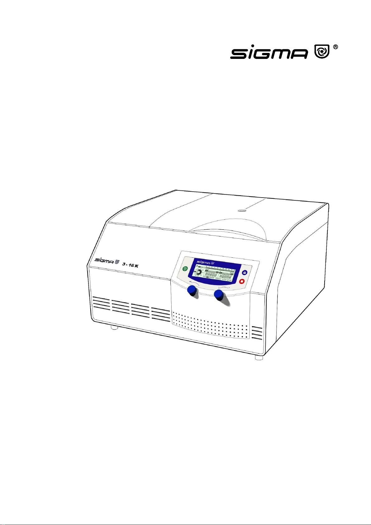
Refrigerated Centrifuge
3-16K
Operating Manual
Page 2

Page 3

Thank you very much for your confidence in the products of our company.
Our centrifuges are manufactured carefully according to the highest quality standards and we
are sure that your demands will always be fulfilled.
Please read this manual carefully before installation of the centrifuge to ensure a proper and
safe operation.
We are wishing you a successful use of the centrifuge.
SIGMA Laborzentrifugen GmbH
P.O. Box 1713 - 37507 Osterode/Germany
Phone 05522/5007-0 - Fax 05522/500712
Internet: www.sigma-zentrifugen.de
eMail: [email protected]
SIGMA Service-Tel. 05522/5007-25
Operating Manual SIGMA 3-16K, page 3 of 69
03/06
Page 4

Page 5
Konformitätserklärung
(73/23/EWG; 89/336/EWG; 98/37/EWG)
Statement of Conformity
(73/23/CEE; 89/336/CEE; 98/37/CEE)
Déclaration de conformité
(73/23/CEE; 89/336/CEE; 98/37/CEE)
Die nachfolgend bezeichnete Maschine wurde in Übereinstimmung mit den Richtlinien
73/23/EWG; 89/336/EWG und 98/37/EWG hergestellt und geprüft.
The following machine is manufactured and tested in compliance with directions 73/23/CEE;
89/336/CEE and 98/37/CEE.
La machine désignée ci-dessous est produit et examiné conforme aux directives 73/23/CEE;
89/336/CEE et 98/37/CEE
Bezeichnung der Maschine: Laborzentrifuge
Machine: Laboratory Centrifuge
Désignation de la machine: Centrifugeuse de laboratoire
Maschinentyp : 3 – 16K
Type:
Type de la machine:
Bestell Nr. : 10280, 10281, 10282, 10283
Part No.:
Réf. usine:
Normen: EN 61010-2-020
Standards: EN 61000-3-2 ; EN 61000-3-3
Normes : EN 61326
Sigma Laborzentrifugen
An der Unteren Söse 50
D-37520 Osterode
19.08.2002 Geschäftsführer
Managing Director
Directeur Gérant
...........................................................................
Fabr. Nr. Serial No. Numéro de fabrique
Konformitätserklärung dreisprachig 3-16K 20020819.DOC
Operating Manual SIGMA 3-16K, page 5 of 69
03/06
Page 6

Page 7

General Information
1.1 Technical data
1.2 Suitable accessories
1.3 Scope of supply
1.4 Standards and regulations
1.5 Safety instructions
1.6 Symbol table
Description of the Centrifuge
2.1 General outlay
2.2 Construction and constructive safety measures
2.3 Drive
2.4 Operation and display
2.5 Electronics
2.6 Safety devices
2.6.1 Lid lock, cover closing device
2.6.2 Standstill monitoring
2.6.3 System check
2.6.4 Ground wire check
2.6.5 Imbalance Monitoring System
Installation and Start-up
3.1 Unpacking of the centrifuge
3.1.1 Transport safety device
3.2 Installation
3.2.1 Site
3.2.2 Connection
3.2.3 Fuses / emergency circuit breaker on site
3.3 Installation of rotors and accessories
3.3.1 Fastening of angle rotors with hermetically sealed lid
3.4 Initial start-up
3.4.1 Switching on of the centrifuge
3.4.2 Opening of the lid
3.4.3 Installation of a rotor
Operating Elements
4.1 Operating panel
4.1.1 Start-key / Saving a program
4.1.2 Stop-key with preselection of the soft stop and/or soft start function
4.1.3 Lid-key
4.1.4 Knobs
Operating Manual SIGMA 3-16K, page 7 of 69
03/06
Page 8

4.2 Displays
4.2.1 Speed/RCF (Relative centrifugal force)
4.2.1.1 Speed
4.2.1.2 Relative centrifugual force (RCF)
4.2.2 Time
4.2.3 Standard time mode
4.2.3.1 Continuous operation mode
4.2.3.2 Short-time operation
4.2.3.2.1 Short-run 1
4.2.3.2.2 Short-run 2
4.2.4 Temperature
4.2.5 Preselection of a rotor
Notes for Centrifugation
5.1 Practical notes for centrifugation
5.2 Forbidden centrifuging operations
Care and Maintenance
6.1 Care and cleaning of centrifuge
6.2 Care and cleaning of accessories
6.3 Rotor pins
6.4 Glass breakage
6.5 Care and cleaning of the condenser
6.6 Sterilization and disinfection of rotor chamber and accessories
6.6.1 Autoclaving
6.7 Checks by operator
7. Appendix
7.1 Mathematical relations
7.1.1 Relative Centrifugal Force (RCF)
7.1.2 Density
7.2 Error correction
7.2.1 Centrifuge cannot be started
7.2.2 Centrifuge decelerates during operation
7.2.3 Lid cannot be opened/closed
7.2.4 Emergency lid release
7.2.5 Problems with the centrifuge?
7.3 Error mode
7.3.1 Error codes
7.4 Diagram speed/gravitational field
7.5 Declaration of decontamination/Return declaration
7.6 Leaflet
Operating Manual SIGMA 3-16K, page 8 of 69
03/06
Page 9
1.1 Technical Data
Manufacturer: S I G M A
Laborzentrifugen GmbH
37520 Osterode
Type: 3-16K
Electr. connection:
Protection class:
Rated power (kW)
Drive:
Refrigerating machine:
Max. current (A):
Power data:
Max. speed (rpm):
Max. capacity (ml):
Max. gravitational field (x g):
Max. kin. energy (Nm):
Further parameters
Time range:
Temperature setting range:
Dimensions:
Depth (mm):
Width (mm):
Height (mm):
Weight (kg):
EMC (acc. to EN 55011):
Noise level (dBA):
Notes of user:
Serial number:
Supply date:
Inventory number:
Location:
Responsibility:
The figures are valid for an ambient temperature of +23 °C +/- 2 °C and nominal voltage +/- 5
%. The minimum temperatures during run are < +4 °C a nd depend on type of rotor, speed and
ambient temperature.
(Allowable ambient temperature +10 °C - +35 °C; max . humidity 80 %.)
Subject to technical alterations.
see nameplate
I
1,01
0,46
0,55
5,5 (230 V/50 Hz) respectively
11 (120 V/60 Hz)
15 300
1000
23 031
9 970
0 - 30 min/continuous run/
short-time operation
-10 to +40 °C
600
630
355
78
Class B
< 65
.....................................................
.....................................................
.....................................................
.....................................................
.....................................................
Operating Manual SIGMA 3-16K, page 9 of 69
03/06
Page 10

Page 11

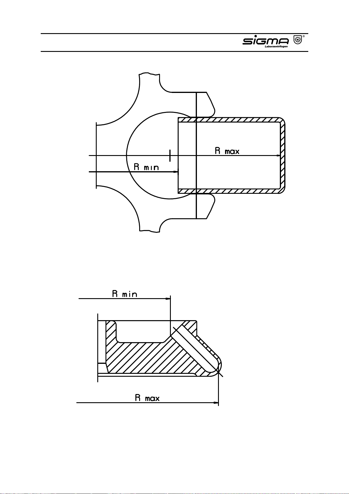
1.2 Accessories Suitable for SIGMA 3-16K
Part No.
11180 Swing-out rotor for 4 buckets for the
13194 Bucket for rectangular carriers 18310,
18310 Rectangular carrier for 4 culture tubes
18311 Rectangular carrier for 10 culture tubes
13180 Rectangular bucket, aluminium, sealable
17112 Sealing cap, polysulfone, clear, incl. 2 clips
18000 Rectangular carrier, undrilled for special
18002 Rectangular carrier for 20 reaction vials
18003 Upper part for 18002 for 20 reaction vials
18005 Rectangular carrier for 20 RIA-tubes 5 ml,
18007 Rectangular carrier for 20 glass tubes 7 ml,
Description
following accessories:
18311 (culture tubes 15 resp. 50 ml), max.
radius 16.8 cm, min. radius 6.6 cm
50 ml, e.g. 15151
15 ml, e.g. 15115
with cap 17112, suitable for the system of
rectangular carriers, suitable for 11180,
max. radius 17.1 cm, min. radius 7.6 cm
17118, suitable for 13180
tubes 85 - 110 mm long, polyallomer
1.5 - 2.2 ml, max. ∅∅∅∅ 11 mm, e.g. 15008,
15040, polypropylene
1.5 - 2.2 ml, e.g. 15008, 15040, can be used
together with 18002, polypropylene
max. ∅∅∅∅ 12.2 x 60 - 75 mm, flat and round
bottom tubes, e.g. 15060, polyallomer
max. ∅∅∅∅ 12.3 x 80 - 105 mm, flat and round
bottom tubes, e.g. 15007, 15027,
polyallomer
Max. speed
(rpm)
4 500
4 500
4 500
Max.
gravitational
field (x g)
3 871/3 894
3 803
3 871
Operating Manual SIGMA 3-16K, page 11 of 69
03/06
Page 12

Part No.
18009 Rectangular carrier for 20 hemolyse tubes,
18010 Rectangular carrier for 12 tubes with screw
18012 Rectangular carrier for 12 Vacutainer-tubes
18015 Rectangular carrier for 12 tubes 10 - 15 ml,
18016 Rectangular carrier for 4 culture tubes
18017 Rectangular carrier for 10 tubes 15 ml, and
18025 Rectangular carrier for 5 glass tubes 25 ml,
18022 Rectangular carrier for 4 sterilin tubes
18030 Rectangular carrier for 5 tubes with screw
18050 Rectangular carrier for 2 tubes 50 ml, max.
Description
max. ∅∅∅∅ 12.8 x 70 - 90 mm, polypropylene
cap 10 - 12 ml, max. ∅∅∅∅ 16.8/17.5 x 60 -
85 mm, e.g. 15000, 15010, 15039,
polyallomer
∅∅∅∅ 13.5/18 x 65 - 90 mm, polypropylene
max. ∅∅∅∅ 17 x 90 - 105 mm, e.g. 15015, 15020,
15022, 15023, 15024, polyallomer
15 ml 15115, polypropylene
tubes with stopper, max. Ø 17.2/18 x 80 111 mm, e.g. Monovettes 9 ml and 10 ml,
polypropylene
max. ∅∅∅∅ 24 x 85 - 105 mm, e.g. 15025, 15026,
polyallomer
30 ml, graduated up to 20 ml, with skirt,
incl. cap, max. ∅∅∅∅ 25/31 x 65 - 95 mm,
polypropylene, see
no. 03008
cap 27 - 30 ml, max. ∅∅∅∅ 25.4/27.5 x 80 -
110 mm, e.g. 15029, 15030, 15032,
polypropylene
∅∅∅∅ 35/38 x 85 - 110 mm, e.g. 15049, 15050,
15056, polyallomer
www.bibby-sterilin.co.uk
,
Max. speed
(rpm)
Max.
gravitational
field (x g)
Operating Manual SIGMA 3-16K, page 12 of 69
03/06
Page 13

Part No.
18051 Rectangular carrier for 2 tubes with screw
18052 Rectangular carrier for 2 culture tubes
18053 Rectangular carrier for 2 culture tubes
18085 Rectangular carrier for 1 tube with screw
18100 Rectangular carrier for 1 tube 100 ml, max.
18105 Rectangular carrier for 20 RIA-tubes 5 ml,
18107 Rectangular carrier for 20 glass tubes 7 ml,
18115 Rectangular carrier for 12 tubes 10 - 15 ml,
18125 Rectangular carrier for 1 bottle with screw
18200 Rectangular carrier for 1 bottle with screw
Description
cap 40 - 50 ml, max. ∅∅∅∅ 29/35 x 80 - 110 mm,
e.g. 13055, 15051, 15052, 15054,
polypropylene
50 ml 15151, polypropylene
50 ml with skirt, max. ∅∅∅∅ 29.5/38 x 85 -
118 mm, polypropylene
cap 78 - 85 ml, max. ∅∅∅∅ 38/40 x 85 - 112 mm,
e.g. 13085, 15074, 15075, 15076, 15080,
polyallomer
∅∅∅∅ 45.5/48 x 85 - 110 mm, e.g. 15100, 15102,
15103, 15106, polyallomer
max. ∅∅∅∅ 12.2 x 60 - 75 mm, flat and round
bottom tubes, e.g. 15060, decantable,
polyallomer
max. ∅∅∅∅ 12.3 x 80 - 105 mm, flat and round
bottom tubes, e.g. 15007, 15027,
decantable, polyallomer
max. ∅∅∅∅ 17 x 90 - 105 mm, e.g. 15015, 15020,
15022, 15023, 15024, decantable,
polyallomer
cap 125 ml, max. ∅∅∅∅ 51 x 90 - 115 mm, e.g.
15125, polypropylene
cap 200 ml, max. ∅∅∅∅ 57 x 90 - 115 mm, e.g.
15202, 15203, polypropylene
Max. speed
(rpm)
Max.
gravitational
field (x g)
Operating Manual SIGMA 3-16K, page 13 of 69
03/06
Page 14

Part No.
11181 Swing-out rotor 48 x 15 ml complete, con-
11182 Swing-out rotor 12 x 50 ml culture tubes
13190 Round bucket, aluminium, sealable with
17190 Sealing cap, polysulfone, clear, suitable for
17350 Round carrier for 24 reaction vials 0.5 -
17351 Round carrier for 12 Monovettes, max.
17352
17353 Round carrier for 16 reaction vials 1.5 -
17354 Round carrier for 16 glass tubes 7 ml, max.
17355 Round carrier for 12 tubes with screw cap
17356 Round carrier for 16 Vacutainer/hemolyse
Description
sisting of rotor 11180, 4 rectangular
buckets 13180, 4 carriers 18015 and 48 PStubes 15020, max. radius 17.1 cm, min.
radius 7.6 cm
complete, consisting of rotor 11180,
4 round buckets 13190, 4 carriers 17346
and 12 culture-tubes 15151, max. radius
17.2 cm, min. radius 7.5 cm
cap 17190, suitable for the following round
carriers, suitable for 11180, max. radius
17.2 cm, min. radius 7.5 cm
13190
0.75 ml, ∅∅∅∅ 8/10 x 28/31 mm, e.g. 15005,
polypropylene
∅∅∅∅ 15.5/18 x 50 - 75 mm, polypropylene
Round carrier for 25 RIA-tubes, max. ∅∅∅∅ 12.5
x 65 - 80 mm, e.g. 15060, polypropylene
2.2 ml, max. ∅∅∅∅ 11 mm, e.g. ml 15008, 15040,
polypropylene
∅∅∅∅ 12.5 x 85 - 115 mm, e.g. 15007, 15027,
polypropylene
10 - 12 ml, max. ∅∅∅∅ 16.2/19 x 65 - 90 mm, e.g.
15000, 15010, 15039, polypropylene
tubes/RIA-tubes 5 - 6 ml, max. ∅∅∅∅ 13.5/17.5 x
70 - 90 mm, e.g. 15060, polypropylene
Max. speed
(rpm)
4 500
4 500
4 500
Max.
gravitational
field (x g)
3 871
3 894
3 894
Operating Manual SIGMA 3-16K, page 14 of 69
03/06
Page 15

Part No.
17358 Round carrier for 12 tubes 10 - 15 ml, max.
17345 Round carrier for 5 culture tubes 15 ml
17362 Round carrier for 5 sterilin tubes 30 ml,
17370
17375 Round carrier for 3 tubes 50 ml, max.
17376 Round carrier for 4 tubes with screw cap
17346 Round carrier for 3 culture tubes 50 ml
17385 Round carrier for 1 tube with screw cap
17390 Round carrier incl. rubber cushion 16051
17395 Round carrier for 1 bottle with screw cap
17400 Round carrier for 1 bottle with screw cap
Description
∅∅∅∅ 17.2/19.5 x 90 - 115 mm, e.g. 15015,
15020, 15022, 15023, 15024, and
Monovettes 9 ml and 10 ml, polypropylene
15115, polypropylene
graduated up to 20 ml, with skirt, incl. cap,
max. ∅∅∅∅ 25/31 x 65 - 95 mm, polypropylene,
see
www.bibby-sterilin.co.uk
Round carrier for 5 tubes 25 - 30 ml, max. ∅∅∅∅
25.4/29 x 85 - 115 mm, e.g. 15025, 15026,
15029, 15030, 15032, 15033, polypropylene
∅∅∅∅ 35/38 x 90 - 110 mm, e.g. 15049, 15050,
15056, polypropylene
40 - 50 ml, max. ∅∅∅∅ 29/34 x 85 - 110 mm, e.g.
15051, 15052, 15054, polypropylene
15151, polypropylene
78 - 85 ml, max. ∅∅∅∅ 38/40 x 85 - 115 mm, e.g.
13085, 15074, 15075, 15076, 15080,
polypropylene
for 1 tube 100 ml, max. ∅∅∅∅ 45/50 x 85 -
110 mm, e.g. 15100, 15102, 15103, 15106,
polypropylene
125 ml, max. ∅∅∅∅ 51 x 90 - 115 mm, e.g. 15125,
polypropylene
200 ml, max. ∅∅∅∅ 57 x 90 - 115 mm, e.g. 15202,
15203, polypropylene
, no. 03008
Max. speed
(rpm)
Max.
gravitational
field (x g)
Operating Manual SIGMA 3-16K, page 15 of 69
03/06
Page 16

Part No.
17347 Round carrier for 1 bottle with screw cap
11240 Swing-out rotor for microtiter-plates, incl. 2
11222 Swing-out rotor for microtiter plates, incl. 2
11133 Swing-out rotor for 4 round buckets, for the
13104 Round bucket, aluminium, sealable with
17109 Sealing cap, aluminium, for hermetic
17111 Sealing cap, polysulfone, clear, for
13117 Round bucket, aluminium, for the following
17000 Round carrier, two-piece, undrilled, for
17006
Description
250 ml, max. ∅∅∅∅ 61.5 x 90 - 125 mm, e.g.
15247, 15248, 15249, polypropylene
buckets 13145 and plate holder 17977,
radius edge 12.7 cm,
radius max. 10.5 cm
radius min. 4.65 cm,
max. plate height 64 mm
carriers 13222
radius edge 12.3 cm,
radius max. 10.5 cm,
radius min. 6.5 cm
max. plate height 56 mm
following accessories:
caps 17109, 17111, for the following round
carriers and the 200 ml bottles 15202 and
15203, suitable for 11133, max. radius
16.1 cm, min. radius 5.7 cm:
sealing of bucket 13104
hermetic sealing of bucket 13104
round carriers and the 200 ml bottles 15202
and 15203, suitable for 11133, max. radius
16.1 cm, min. radius 5.7 cm
tubes 90 - 110 mm long, polyallomer
Round carrier for 12 tubes 5 ml, max. ∅∅∅∅
12.5 x 55 - 75 mm, e.g. hemolyse tubes or
RIA-tubes 15060, polyallomer
Max. speed
(rpm)
3 850
3 000
5 500
5 500
5 500
Max.
gravitational
field (x g)
2 105
1 740
770
1 238
1 057
654
5 445
5 445
5 445
Operating Manual SIGMA 3-16K, page 16 of 69
03/06
Page 17

Part No.
17007 Round carrier for 12 glass tubes 7 ml, max.
17008 Round carrier for 12 reaction vials 1,5 -
17027 Round carrier for 7 Vacutainer-tubes, max.
17012 Round carrier for 6 tubes with screw cap
17013
17015
17018 Round carrier for 4 tubes with sealing cap
17019 Round carrier for 3 culture tubes 15 ml
17025 Round carrier for 2 glass tubes 25 ml, max.
17032 Round carrier for 1 sterilin tube 30 ml,
17030 Round carrier for 2 tubes with screw cap
17049 Round carrier for 1 culture tube 50 ml
Description
∅∅∅∅ 12.3 x 90 - 105 mm, e.g. 15007, 15027,
polyallomer
2,2 ml, max. ∅∅∅∅ 11 mm, e.g. 15008, 15040,
polypropylene
∅∅∅∅ 13.5/17.5 x 65 - 90 mm, polypropylene
10 - 12 ml, max. ∅∅∅∅ 16.5/17.5 x 58 -90 mm,
e.g. 15000, 15010,15039, polyallomer
Round carrier for 9 hemolyse tubes, max. ∅∅∅∅
12,9 x 85 mm, polypropylene
Round carrier for 7 tubes 10 - 15 ml, max. ∅∅∅∅
16.8 x 90 - 105 mm, e.g. 15015, 15020,
15022, 15023, 15024, polyallomer
10 - 15 ml, max. ∅∅∅∅ 17/20 x 90 - 110 mm and
Monovettes, polyallomer
15115, polypropylene, suitable for 13104
without sealing cap
∅∅∅∅ 24.5 x 90 - 105 mm, e.g. 15025, 15026,
polyallomer
graduated up to 20 ml, with skirt, incl. cap,
max. ∅∅∅∅ 25/31 x 65 - 95 mm, polypropylene,
see
www.bibby-sterilin.co.uk
27 - 30 ml, max. ∅∅∅∅ 25.4/27.5 x 85 - 100 mm,
e.g. 15029, 15030, 15032, polypropylene
15151, polypropylene
, no. 03008
Max. speed
(rpm)
Max.
gravitational
field (x g)
Operating Manual SIGMA 3-16K, page 17 of 69
03/06
Page 18

Part No.
17050
17052 Round carrier for 1 tube with screw cap
17085 Round carrier for 1 tube with screw cap
17100 Round carrier for 1 tube 100 ml, max.
17101 Round carrier for 1 tube 100 ml, max.
17125 Adapter for 1 bottle with screw cap 125 ml,
11132 Swing-out rotor 28 x 15 ml complete, con-
11224 Swing-out rotor for cytology, complete,
11136 Rotor for reaction vials (max. 60/120 pcs.)
14000 Casset for 20 reaction vials 0.25 - 0.4 ml
Description
Round carrier for 1 tube 50 ml, max. ∅∅∅∅
35/38 x 85 - 115 mm, e.g. 15049, 15050,
15056, polyallomer
40 - 50 ml, max. ∅∅∅∅ 29/35 x 85 - 115 mm, e.g.
13055, 15051, 15052, 15054, polyallomer
78 - 85 ml, max. ∅∅∅∅ 38/40 x 85 - 112 mm, e.g.
13085, 15074, 15075, 15076, 15080,
polyallomer
∅∅∅∅ 45.5 x 85 - 105 mm, e.g 15100, 15103,
15106, polyallomer
∅∅∅∅ 45.5 x 85 - 105 mm, e.g. 15100, 15102,
15103, 15106, polypropylene
max. ∅∅∅∅ 51 x 90 - 120 mm, e.g. 15125,
polypropylene
sisting of rotor 11133, 4 round buckets
13117, 4 carriers 17015 and 28 PS-tubes
15020, max. radius 14.9 cm, min. radius
5.7 cm
incl. 4 buckets and carriers for different
object carriers. The buckets with object
carriers could be locked in 90° position,
max. radius 11.3 cm
incl. cover, for carriers 14000, 14002, 14020
and 14021, max. radius 7 cm, min. radius 3
cm. Attention: The vessels could be
damaged at speeds exceeding 13 000 rpm
15014, suitable for 11136, polyallomer
Max. speed
(rpm)
5 500
3 000
14 500
Max.
gravitational
field (x g)
5 039
1 137
16 454
Operating Manual SIGMA 3-16K, page 18 of 69
03/06
Page 19

Part No.
14002 Casset for 10 reaction vials 1.5 - 2.2 ml
14020 Casset for 10 PCR tubes 0.2 - 0.5 ml,
14021 Casset for 32 PCR tubes 0.2 ml or 4 strips
11135 Swing-out rotor 24 x 1.5 - 2.2 ml for reaction
12154 Angle rotor 24 x 1.5 - 2.2 ml for reaction
12131 Angle rotor 30 x 1.5 - 2.2 ml for reaction
12348 Angle rotor 48 x 1.5 - 2.2 ml for reaction
12115 Angle rotor for 12 strips with 8 PCR tubes
12111 Angle rotor 10 x 10 - 12 ml for sealed tubes
12157 Angle rotor 20 x 10 - 12 ml for sealed tubes
Description
15008, 15040, suitable for 11136,
polyallomer
suitable for 11136, polypropylene
with 8 PCR tubes 0.2 ml each, suitable for
11136, polypropylene
vials e.g. 15008, 15040, incl. hermetic
aluminium lid, max. radius 7.4 cm, min.
radius 3.5 cm
vials e.g. 15008, 15040, incl. hermetic
aluminium lid, max. radius 8.2 cm, min.
radius 5 cm, angle 45°
vials e.g. 15008, 15040, incl. hermetic
aluminium lid, max. radius10 cm, min.
radius 6.7 cm, angle 45°
vials e.g. 15008, 15040, incl. hermetic
aluminium lid, max. radius 8.4 cm, min.
radius 5.1 cm
0.2 ml each, incl. hermetic aluminium lid,
max. radius 9.8 cm, min. radius 7.2 cm,
angle 45°
15000, 15010, 15039, incl. hermetic
aluminium lid, max. radius 7.6 cm, min.
radius 2.8 cm, angle 35°
15000, 15010, 15039, incl. hermetic
aluminium lid, max. radius 9.8 cm, min.
radius 5.9 cm, angle 25°
Max. speed
(rpm)
14 000
15 300
14 000
15 300
14 000
15 300
10 000
Max.
gravitational
field (x g)
16 215
21 460
21 913
21 984
15 777/21 475
19 890
10 956
Operating Manual SIGMA 3-16K, page 19 of 69
03/06
Page 20

Part No.
12112 Angle rotor 12 x 15 ml for Greiner-tubes
19777 Angle rotor for 10 culture tubes 15 ml
12158 Angle rotor 6 x 27 - 30 ml for sealed tubes
12150 Angle rotor 6 x 40 - 50 ml for sealed tubes
12156 Angle rotor 8 x 50 ml for sealed tubes 13055
19776 Angle rotor for 6 culture tubes 50 ml 15151,
13060 Adapter for 1 culture tube 15 ml 15115,
13079 Bottom adapter for 1 tube 40 - 42 ml 15051,
12155 Angle rotor 4 x 78 - 85 ml for sealed tubes
12159 Angle rotor 6 x 78 - 85 ml for sealed tubes
Description
with cap 15065 (Greiner no. 187261), max.
Ø 17/22 x 95/100 mm, max. radius 10 cm,
min. radius 4.8 cm
15115, incl. hermetic aluminium lid, max.
radius 9.3 cm, min. radius 3.7 cm, angle 25°
15029, 15030, 15032, incl. hermetic
aluminium lid, max. radius 7.9 cm, min.
radius 2.3 cm, angle 30°
13055 plus 17054, 15051, 15052, 15054, incl.
hermetic aluminium lid, max. radius 8.4 cm,
min. radius 2.1 cm, angle 25°
plus 17054, 15051, 15052, 15054, incl.
hermetic aluminium lid, max. radius 9.6 cm,
min. radius 3.3 cm, angle 25°
incl. hermetic aluminium lid, max. radius
9.3 cm, min. radius 3.1 cm, angle 25°
suitable for 19776, polypropylene
15052, 15054, suitable for 19776,
polypropylene
13085 plus 17185, 15074, 15075, 15076,
15080, incl. hermetic aluminium lid, max.
radius 9.1 cm, min. radius 1.4 cm, angle 30°
13085 plus 17185, 15074, 15075, 15076,
15080, incl. hermetic aluminium lid, max.
radius 9.8 cm, min. radius 2.8 cm, angle 25°
Max. speed
(rpm)
9 000
9 500
15 300
11 000
10 000
9 500
10 000
8 000
Max.
gravitational
field (x g)
9 056
9 384
20 675
11 363
10 733
9 384
10 174
7 012
Operating Manual SIGMA 3-16K, page 20 of 69
03/06
Page 21

Part No.
13080 Adapter for 1 culture tube 50 ml 15151,
13081 Adapter for 1 culture tube 15 ml 15115,
13082
13083
13084
Adapters, tubes and steel tubes
13000 Adapter , POM, for reaction vials 0.25 -
13002 Adapter, POM, for reaction vials 0.5 -
13021 Adapter for PCR tube 0.2 ml, Ø 5.85/6.95 x
15005
15008 Reaction vials 1.5 ml, 1 pack contains 100
Description
suitable for 12155 without lid, 12159,
polypropylene
suitable for 12155 without lid, 12159,
polypropylene
Adapter for 1 tube 40 - 50 ml, max. ∅∅∅∅ 28.8 x
105 - 110 mm, e.g. 13055, 15051, 15052,
15054, suitable for 12155, 12159,
polypropylene
Adapter for 1 tube 27 - 30 ml, max. ∅∅∅∅ 25.5 x
90 - 100 mm, e.g. 15029, 15030, 15032,
suitable for 12155, 12159
Adapter for 2 tubes 10 - 12 ml, max. ∅∅∅∅
16/17.5 x 75 - 90 mm, e.g. 15000, 15010,
15039, suitable for 12155, 12159,
polypropylene
0.4 ml 15014, suitable for 12110, 12131,
12154, 12348, 14002, 17008, 18002
0.75 ml 15005, ∅∅∅∅ 7.9/10 x 28/31 mm suitable
for 12110, 12131, 12154, 12348, 14002,
17008, 18002,
20/23.4 mm, suitable for 12110, 12131,
12154, 12348, 14002, 17008, 18002
Reaction vials 0.5 ml, ∅∅∅∅ 7.9/10 x 28/31 mm,
1 pack contains 100 pcs., suitable for
13002, 17350
pcs., suitable for 12110, 12131, 12154,
12348, 14002, 17008, 17353, 18002
Operating Manual SIGMA 3-16K, page 21 of 69
03/06
Page 22

Part No.
15040 Reaction vials 2.2 ml, 1 pack contains 100
15014 Reaction vials 0.4 ml (Beckman system),
15060 Polystyrene tube 5 ml (RIA-tube),
13026
17126 Stainless steel sealing cap for 13026
15000
15010 ditto, polycarbonate
15039 ditto, polypropylene
15020
15021 Polypropylene stopper for 15020, 15023
15023
15065
15115 Culture tube with screw cap 15 ml, pointed
15029
Description
pcs., suitable for 12110, 12131, 12154,
12348, 14002, 17008, 17353, 18002
polypropylene, 1 pack contains 100 pcs.,
suitable for 13000, 14000
∅∅∅∅ 12 x 75 mm, suitable for 17006, 17356,
18005, 18009
Stainless steel tube 10 ml, ∅∅∅∅ 15.7 x
76 mm, sealable with cap 17126, suitable
for 12111, 12157
Teflon tube with screw cap 12 ml, ∅∅∅∅ 16.1 x
81.1 mm, suitable for 12111, 12157, 13084,
17012, 17355, 18010
Polystyrene tube 15 ml, ∅∅∅∅ 17 x 100 mm,
suitable for 17015, 17358, 18015, 18115
Polypropylene tube 15 ml, ∅∅∅∅ 17 x 100 mm,
suitable for 17015, 17358, 18015, 18115
Plastic tube with cap 15 ml, ∅∅∅∅ 17/22 x
94/95 mm (Greiner no. 187261), suitable for
12112
bottom, polypropylene, suitable for 13060,
13081, 17019, 17345, 18016, 19777
Teflon tube with screw cap 28 ml, ∅∅∅∅ 25.3 x
96 mm, suitable for 12158, 13083, 17030,
17370, 18030
Operating Manual SIGMA 3-16K, page 22 of 69
03/06
Page 23

Part No.
15030 Polycarbonate tube with screw cap 30 ml,
15032 Polypropylene tube with screw cap 27 ml,
15049 Polycarbonate tube 50 ml, graduated,
13055 Stainless steel tube 50 ml, sealable with
17054 Stainless steel sealing cap for 13055
15051
15052 Polypropylene tube with screw cap 42 ml,
15054 Polycarbonate tube with screw cap 40 ml,
15048 Polyallomer tube with screw cap 42 ml,
15151 Culture tube with screw cap 50 ml, pointed
13085 Stainless steel tube 85 ml, sealable with
17185 Stainless steel sealing cap for 13085
Description
∅∅∅∅ 25.3 x 98 mm, suitable for 12158, 13083,
17030, 17370, 18030
∅∅∅∅ 25.3 x 97 mm, suitable for 12158, 13083,
17030, 17370, 18030
Ø 34 x 100 ml, suitable for 17050, 17375,
18050
sealing cap 17054, ∅∅∅∅ 29 x 101.5 mm,
suitable for 12150, 12156, 13082, 17052,
17375, 18051
Teflon tube with screw cap 42 ml, ∅∅∅∅ 28.5
x 107 mm, suitable for 12150, 12156, 13082,
17052, 17376, 18051
∅∅∅∅ 28.8 x 107 mm, suitable for 12150, 12156,
13082, 17052, 17376, 18051
∅∅∅∅ 28.8 x 107 mm, suitable for 12150, 12156,
13082, 17052, 17376, 18051
∅∅∅∅ 28.5 x 107 mm, suitable for 12150, 12156,
13082, 17052, 17376, 18051
bottom, polypropylene, suitable for 13080,
17049, 17346, 18052, 19776
sealing cap 17185, ∅∅∅∅ 38/40 x 100/107 mm,
suitable for 12155, 12159, 17085, 17385,
18085
Operating Manual SIGMA 3-16K, page 23 of 69
03/06
Page 24

Part No.
15074 Polycarbonate tube 82 ml with special
15075 Polycarbonate tube with screw cap 82 ml,
15076 Polypropylene tube with screw cap 78 ml,
15080
15102
15103
15125 Polypropylene bottle with screw cap
15202 Polypropylene bottle with screw cap
15203 Polycarbonate bottle with screw cap
13255 Stainless steel bottle 250 ml, sealable with
17256 Stainless steel sealing cap for 13255
15247 Teflon bottle with screw cap 250 ml,
Description
screw cap made of aluminium with seal for
high speeds, ∅∅∅∅ 38 x 109 mm, suitable for
12155, 12159, 17085, 17385, 18085
∅∅∅∅ 38 x 112 mm, suitable for 12155, 12159,
17085, 17385, 18085
∅∅∅∅ 38 x 112 mm, suitable for 12155, 12159,
17085, 17385, 18085
Polyflor tube with screw cap 81 ml, ∅∅∅∅ 38 x
112 mm, suitable for 12155, 12159, 17085,
17385, 18085
Polypropylene tube 100 ml, ∅∅∅∅ 45 x 100 mm,
suitable for 17101, 17390, 18100
Polycarbonate tube 100 ml, ∅∅∅∅ 45 x 100 mm,
graduated, suitable for 17100, 17101, 17390,
18100
125 ml, ∅∅∅∅ 51 x 99 mm, suitable for 17125,
17395, 18125
185 ml, ∅∅∅∅ 56,5 x 113 mm, suitable for 13104,
13117, 17400, 18200
200 ml, ∅∅∅∅ 56 x 112 mm, suitable for 13104,
13117, 17400, 18200
sealing cap 17256, Ø 61.4 x 125 mm,
suitable for 17347
Ø 61.4 x 122 mm, suitable for 17347
Operating Manual SIGMA 3-16K, page 24 of 69
03/06
Page 25

Part No.
15248 Polycarbonate bottle with screw cap 250
15249 ditto, polypropylene
Glass tubes
15007
15027 ditto, graduated
15015
15024 ditto, graduated
15022
15025
15026 ditto, graduated
15033
15050
15056 ditto, graduated
15100
15106 ditto, graduated
Description
ml, Ø 61.4 x 125 mm, suitable for 17347
Glass tube 7 ml, ∅∅∅∅ 12 x 100 mm, suitable
for 17007, 17354, 18007, 18107
Glass tube 10 - 12 ml, ∅∅∅∅ 16 x 100 mm,
suitable for 17015, 17358, 18015, 18115
Special glass tube 15 ml, ∅∅∅∅ 17 x 110 mm,
suitable for 12150, 12156 with 16018 and for
12155, 12159 with 16019, max. permitted
speed 7 000 rpm
Glass tube 25 ml, ∅∅∅∅ 24 x 100 mm, suitable
for 17025, 17365, 18025
Special glass tube 30 ml, ∅∅∅∅ 24 x 105 mm,
suitable for 12150, 12156 with 16030 and for
12155, 12159 with 16031, max. permitted
speed 7 000 rpm
Glass tube 50 ml, ∅∅∅∅ 34 x 100 ml, suitable for
17050, 17375, 18050
Glass tube 100 ml, ∅∅∅∅ 44 x 100 mm, suitable
for 17100, 17101, 17390, 18100
Operating Manual SIGMA 3-16K, page 25 of 69
03/06
Page 26

Part No.
Further accessories
16018 Rubber adapter for 15 ml glass tube 15022,
16019 Rubber adapter for 15 ml glass tube 15022,
16030 Rubber adapter for 30 ml glass tube 15033,
16031 Rubber adapter for 30 ml glass tube 15033,
16906 Rubber plate for 18025
16907 ditto, for 18050
16908
16909 Rubber plate for rectangular carriers 18005,
16910 Rubber plate for round carriers 17006,
16911 Rubber plate for round carriers 17050,
17112 Rectangular sealing cap, polysulfone, clear,
17111 Round sealing cap, polysulfone, clear, for
16251 Sealing ring 58 x 3 mm for 13104
17190 Round sealing cap, polysulfone, clear, for
17919 Table for centrifuge made of sheet-steel,
17913 Fasteners for table 17919
Further accessories are available on request.
Description
suitable for 12150, 12156
suitable for 12155, 12159
suitable for 12150, 12156
suitable for 12155, 12159
ditto, for 18100
18007, 18015
17007, 17012, 17015, 17025
17100
incl. 2 clips 17118, for 13180
13104
13190
varnished, with 2 doors and space for
accessories, movable on lockable castors,
dimensions: w 490, d 635, h 490 mm
Operating Manual SIGMA 3-16K, page 26 of 69
03/06
Page 27

Maximum speed for tubes
Some tubes, e.g. glass tubes, microtubes, culture tubes, Teflon tubes and especially
high volume tubes can be used in our rotors, buckets and adapters at speeds
exceeding their breaking limit. We recommend to always fill up the tubes and to follow
the recommendations of the manufacturer.
Operating Manual SIGMA 3-16K, page 27 of 69
03/06
Page 28
Operating Manual SIGMA 3-16K, page 28 of 69
03/06
Page 29

1.3 Scope of Supply
The following belongs to the centrifuge:
Connection cable Part No. 269 010
Rotor wrench Part No. 930 100
20 ml slushing oil Part No. 70104
1 tube of grease for load-bearing bolts Part No. 70284
Documentation:
Operating Manual
"Rotor and Accessories, Operation and Use"
EU-Statement of Conformity
Equipment Decontamination Certificate
Accessories according to your order, our order confirmation and our delivery
note.
Rotor Part No. Rotor No.
....................... .....................
....................... .....................
....................... .....................
....................... .....................
....................... .....................
....................... .....................
....................... .....................
1.4 Standards and Regulations
Please refer to the enclosed EU-Statement of Conformity.
Operating Manual SIGMA 3-16K, page 29 of 69
03/06
Page 30

1.5 Safety Instructions
According to the German trade association regulation BGR500 chapter 2.11
part 3 the owner of the instrument is advised to take care of the following points:
1. According to BGR500 the owner has to provide operating instructions
based on those of the manufacturer and to inform the employees
accordingly.
2. For safety reasons these operating instructions must clearly state that the
stamped max. speed of the used rotor and the max. allowable filling
quantity must not be exceeded.
3. If the density of the material exceeds 1.2 g/cm3, the max. speed of the
centrifuge must be reduced (see formula chapter 7.1.2).
4. Operation of the centrifuge in hazardous locations is not allowed.
5. During operation the centrifuge must not be moved. Leaning against or
resting on the centrifuge is not allowed.
6. Do not spin explosive or highly inflammable materials.
7. Substances which could damage the material of the centrifuge, the rotors
or the buckets anyhow must not be centrifuged or only under consideration
of special safety measures. Infectious, toxic, pathogene or radioactive
substances must be centrifuged in certified rotors only.
8. Keep a clearance of at least 30 cm around the centrifuge. Dangerous
materials of any kind must not be put down or stored in that area.
9. Attention!
Defective lid relieving devices could cause the centrifuge lid to fall down
(contact Service). Risk of bruising!
Operating Manual SIGMA 3-16K, page 30 of 69
03/06
Page 31
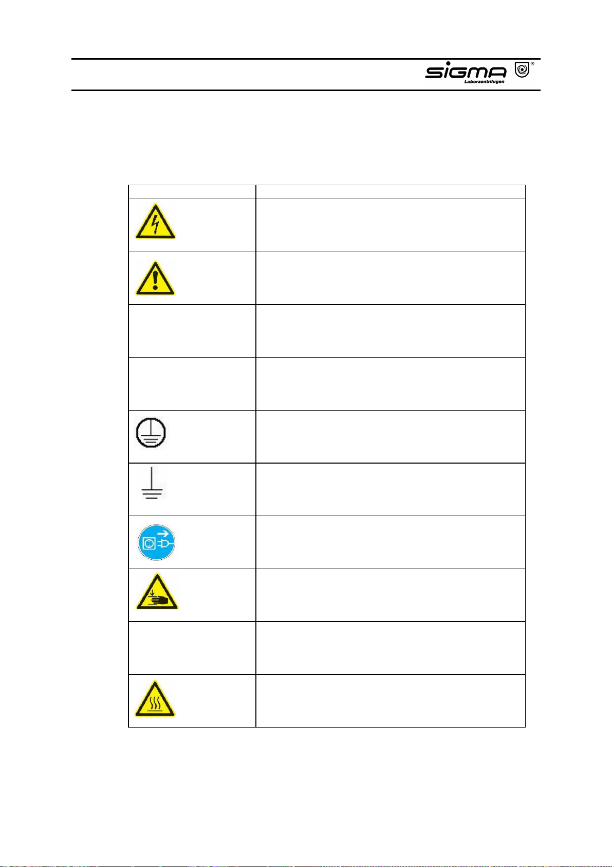
1.6 Symbol Table
International symbols used for the centrifuge:
Symbol Title
Gefährliche elektrische Spannung
Achtung, Bedienungsanleitung beachten
Ein (Netzverbindung)
I
Aus (Netzverbindung)
O
Schutzleiteranschluß
Erde
Netzstecker ziehen
Vorsicht Quetschgefahr
Drehrichtungspfeil
→
Heiße Oberfläche
Dangerous voltage
Courant haute tension
Attention, consult accompanying documents
Attention, consulter les documents joints
On (Power)
Marche (mise sous tension)
Off (Power)
Arrêt (mise hors tension)
Protective earth (ground)
Liaison à la terre
Earth (ground)
Terre
Unplug mains plug
Tirer la fiche de prise
Caution! Risk of bruising
Attention! Danger de blessure
Arrow direction of rotation
Flèche sens de rotation
Hot surface
Surface chaude
Operating Manual SIGMA 3-16K, page 31 of 69
03/06
Page 32

2.1 General Outlay
The new generation of SIGMA laboratory centrifuges is equipped with newest
state-of-the-art electronics and is driven by brushless, silent and long-life asynchronous motors.
The problem of carbon brush change is no longer existent and as there is no
carbon dust pollution, operation in clean rooms is possible if the appropriate
accessories are used.
2.2 Construction and Constructive Safety Measures
The centrifuge is built into a solid steel housing. The centrifuge lid is also made of
solid steel. From the back, the lid is secured by solid hinges and at the front by a
cover lock.
2.3 Drive
The drive motor is a well dimensioned asynchronous motor.
2.4 Operation and Display
The grafical LCD display is hermetically sealed, operation is executed via two
knobs. Any operating status is indicated.
2.5 Electronics
The electronics controlled by a microprocessor allows extensive adaptations of
the centrifuge to the different tasks. The following parameters can be set:
− Speed in steps of 1 respectively 100 rpm *
− RCF in steps of 1 respectively 10 x g *
− Time in steps of 1 min respectively 1 sec
− Continuous operation
− Short-time operation
− Temperature setting range between – 10 °C and + 40 °C in steps of 1 °C
− Preselection of rotor
* Preselection of 1 x g respectively 1 rpm by pressing and holding
(2 – 3 seconds) the stop key.
Operating Manual SIGMA 3-16K, page 32 of 69
03/06
Page 33

2.6 Safety Devices
Apart from the passive safety devices due to the instrument's mechanical design
there are the following active precautions for your safety:
2.6.1 Lid Lock, Cover Closing Device
The centrifuge can only be started when the lid is correctly closed and the lock
has latched. The lid can only be opened when the rotor has stopped. If the lid is
opened via the emergency release during operation (which is not allowed), the
centrifuge will immediately switch off and decelerate brakeless. If the lid is open,
the drive is completely separated from the mains supply, that means starting of
the centrifuge is impossible (refer to point 7.2.4 "Emergency lid release").
2.6.2 Standstill Monitoring
Opening of the centrifuge lid may only be possible, if the rotor is at standstill. This
standstill is checked by the microprocessor.
2.6.3 System Check
An internal system check monitors data transmission and the sensor signals with
regard to plausibility. In case of a malfunction an error message is displayed
under a number in the “Speed“ and “rcf“ display.
2.6.4 Ground Wire Check
For ground wire check there is a ground screw at the rear panel of the centrifuge.
A ground wire check can be carried out using an appropriate measuring
instrument.
2.6.5 Imbalance Monitoring System
The display “Imbalance“ indicates by lightning up that the centrifuge is in the still
permitted imbalance area.
In the event that bigger uneven loading leads to imbalance, the drive is switched
off during acceleration or during run.
“Imbalance“ is flashing and “ERROR“ is displayed. The centrifuge has to be
opened with the lid key. In both cases the loading has to be checked and
balanced.
Operating Manual SIGMA 3-16K, page 33 of 69
03/06
Page 34

3.1 Unpacking of the Centrifuge
Open cardboard. Take out the box containing accessories. Remove upper foam
cushions. Lift centrifuge upwards with a lifting device or with several persons.
When lifting or carrying the centrifuge please always reach under the instrument
from the side.
Proceeding when using a slip box:
Remove cover of cardboard box and take out accessories. Remove upper foam
cushions and remove slip box. Lift centrifuge upwards with a lifting device or with
several persons. When lifting or carrying the centrifuge please always reach
under the instrument from the side.
Attention: The instrument is heavy!
Please keep case for possible transport of centrifuge later.
3.1.1 Transport Safety Device (made of foamed material)
The SIGMA 3-16K has a transport safety device between the rotor chamber and
the motor.
It is accessible after opening of the centrifuge lid (refer to chapter 3.3 up to 3.4.2
or 7.2.4“ Emergency lid release“).
The transport safety device has to be removed, the motor is slightly lifted at the
shaft.
Align centrifuge and continue start-up.
The transport safety device should be kept for possible transport of the centrifuge
(service, repair).
Operating Manual SIGMA 3-16K, page 34 of 69
03/06
Page 35

3.2 Installation
3.2.1 Site
All energy consumed by the centrifuge is converted into heat and emitted into the
ambient air. Therefore, sufficient ventilation is important. As the air-ducts in the
unit must be open, keep a clearance of at least 30 cm around the centrifuge.
Also, the centrifuge shouldn`t be positioned near radiators and should not be
directly exposed to sunshine.
The table should have a solid, even top.
For normal operation the ambient temperature should not fall below 10 °C and
not exceed 35 °C. The max. humidity of air is 80 %. During transport from cold to
warmer places water will condensate inside the centrifuge. It is important that
there is enough time for drying before the centrifuge can be started again.
3.2.2 Connection
The operating voltage on the name plate must correspond to the local supply
voltage!
SIGMA laboratory centrifuges are units of safety class I, DIN VDE 0700, and include a three wire power cord 2,5 m long with shockproof right angle plug. The
instrument has thermal fuses. In case of a disconnection through the thermal
fuses, allow a cool-down phase of two minutes, after which they could be
reactivated by a switch.
At the back, next to the mains supply, there is an additional ground wire
connection where a separate ground wire can firmly be connected to ground any
non-hazardous leakage current. The leakage current is harmless but secondary
effects would occur.
3.2.3 Fuses / Emergency Circuit Breaker on Site
Each centrifuge must be protected with a 16 A time lag fuse.
An emergency circuit breaker to cut the power to the centrifuge in the event of a
malfunction is required on site. This switch should be located away from the
centrifuge, preferably outside the room where the centrifuge is used or at the exit
of this room.
Operating Manual SIGMA 3-16K, page 35 of 69
03/06
Page 36
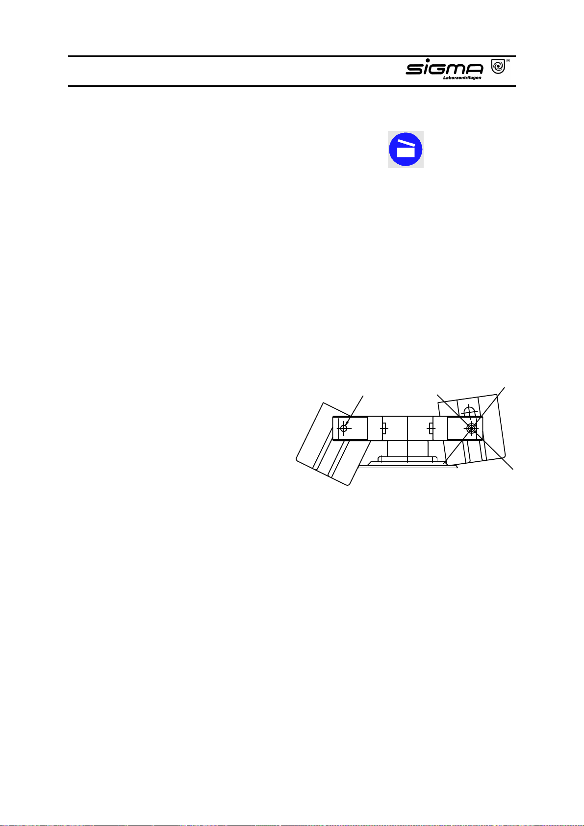
3.3 Installation of Rotors and Accessories
1. Open centrifuge lid by pressing Lid-key.
2. Unscrew rotor tie-down screw from motor shaft (anticlockwise).
3. Lower the rotor straight down onto the motor shaft.
4. Tighten the tie-down screw (clockwise) with the rotor wrench so that the disc
spring is pressed together.
Fastening torque: 1-6/1-13/1-15/2-5/1-15K/2-16/2-16K/
2-16KC:
3-16/3-16K/3-18K/3K 30: approx. 7,5 Nm
4-15/4K15/6-15/6K15: approx. 10 Nm
In the event of frequent use the tie-down screw must be loosened by some
turns and fastened again. This should be done once a day or after approx.
20 cycles. This ensures a proper connection between rotor and shaft (please
refer to chapter 6.2 "Care and cleaning of accessories" as well).
5. Fill all positions of swing-out
rotors with buckets. Make
sure that all buckets are
inserted correctly.
6. Use only appropriate vessels
for the rotor (please refer to
chapter 1.2 "Suitable accessories" as well).
7. Fill vessels external to the centrifuge.
8. Put or screw on covers of vessels.
9. Opposite places of the rotors must always be loaded with same accessories
and same filling.
10. In angle rotors the plastic vessels must always be totally filled to avoid cracks
of vessels and leakages or loosening of the caps in case of partial filling.
Attention, follow the special comments of chapter 1.5.
11. Attention: The centrifuge will absorb smaller differences in weight when
loading the rotors. But it is recommended to balance the vessels as
accurately as possible in order to ensure a run with minimal vibrations.
Should the centrifuge be operated with very uneven load, the imbalance
monitoring will switch off the drive. An imbalance warning would be displayed
(refer to 4.1).
allowed not allowed
Universal grease
approx. 5 Nm
Operating Manual SIGMA 3-16K, page 36 of 69
03/06
Page 37

12. Rotors with lid should always be run with their lid. The rotor lid is tightened by
hand. Correct fastening must be ensured. Attention: The lid screw serves
for fastening of the lid onto the rotor only, not for fastening of the rotor
onto the drive! Before installation of the lid, the correct fastening of the rotor
fixing screw must always be checked using a wrench.
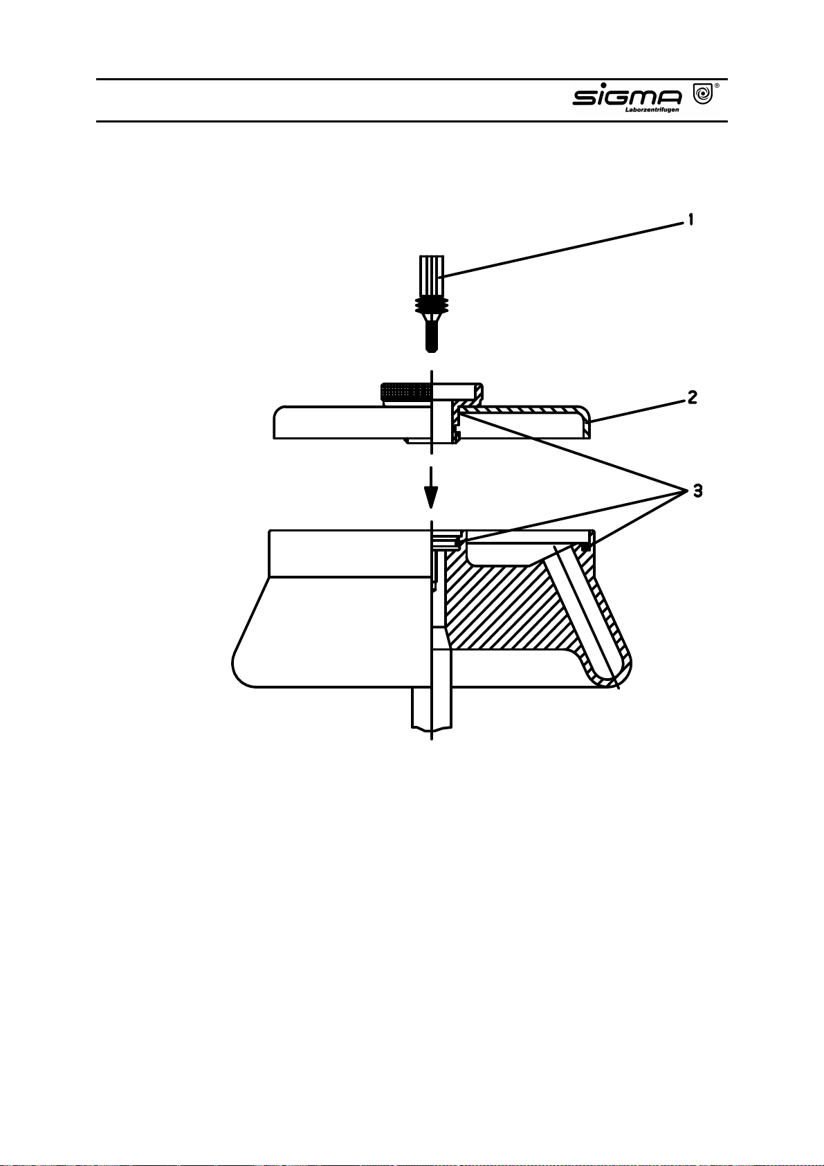
3.3.1 Fastening of Angle Rotors with Hermetically Sealed Lid
(Please refer to drawing on next page.)
1. Screw rotor lid (2) onto rotor and tighten it.
2. Lower rotor with lid (2) onto motor shaft.
3. Put rotor tie-down screw (1) onto motor shaft and tighten using the wrench.
4. The rotor can be run without lid (2) as well.
5. The rotor and lid seals (3) must be greased after cleaning.
6. Special instructions for the use of hermetically sealed rotors:
All rotors can be installed or removed with closed lid after loosening the rotor
tie-down screw. All rotors are autoclavable (refer to chapter 6.6 "Sterilization
and disinfection of rotor chamber and accessories").
To increase life of rotors and seals the rotors must be cleaned with slushing
oil and the seals and thread areas with vaseline or grease after cleaning.
Attention!
Please follow the special comments of chapter 1.5.
Operating Manual SIGMA 3-16K, page 37 of 69
03/06
Page 38
Operating Manual SIGMA 3-16K, page 38 of 69
03/06
Page 39
3.4 Initial Start-Up
Attention!
Before initial start-up please take care that your centrifuge is orderly installed
(refer to chapter 3.2 "Installation").
3.4.1 Switching on of the Centrifuge
Press mains switch (on the right side panel).
− The centrifuge display is illuminated.
3.4.2 Opening of the Lid
Press the lid-key.
− The lid opens.
3.4.3 Installation of a Rotor
Put a rotor onto the shaft and fasten it by screwing the rotor tie-down screw
clockwise onto the drive shaft. Please use the supplied rotor wrench (refer to
chapter 3.3 "Installation of rotors and accessories").
Operating Manual SIGMA 3-16K, page 39 of 69
03/06
Page 40
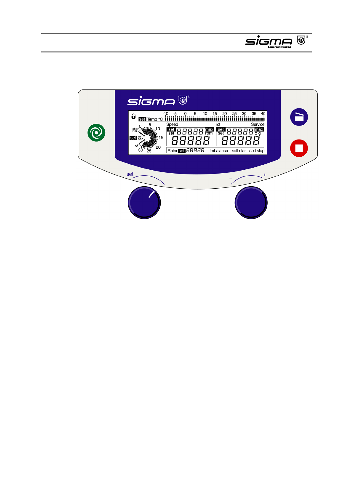
4.1 Operating Panel
The centrifuge is operated via the operating panel. Keys can be pressed when
their LED is on.
When power is applied, all LEDs and the display are illuminated for a short time.
Operating Manual SIGMA 3-16K, page 40 of 69
03/06
Page 41
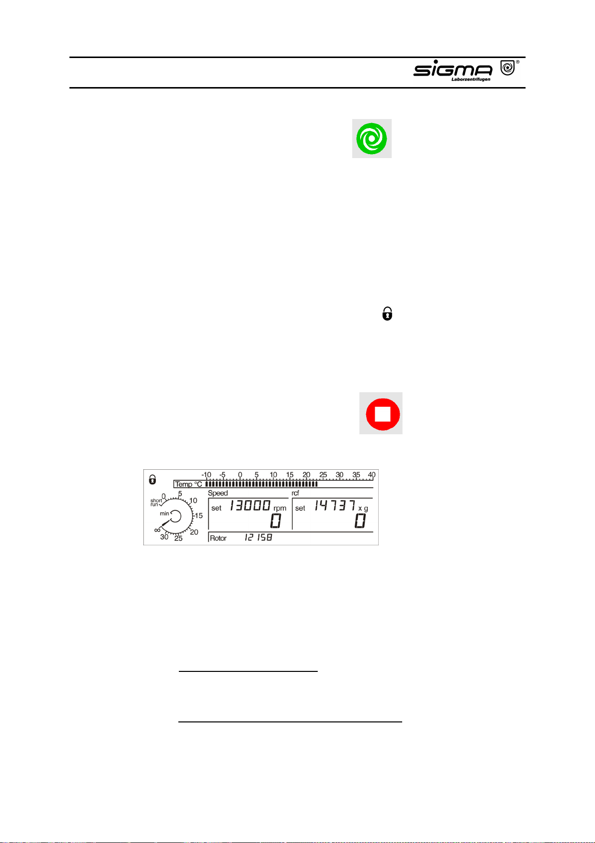
4.1.1 Start-key
This key can be used for the following:
• starting centrifuge operation when the lid is closed and the start-key is illuminated,
• terminating a previously started deceleration process and restarting the
centrifuge,
• shifting to short-run (refer to chapters 4.2.3.2.1, 4.2.3.2.2),
• saving a program. The parameters speed, time and rotor preselection can be
locked, thereafter a change is impossible. Starting and stopping the centrifuge
and opening of the lid is always possible.
Open centrifuge lid. Press the start-key 3 x and hold for approx. 2 seconds
when pressing for the third time. The symbol " " in the display is flashing.
Cancellation of this function occurs in the same way.
4.1.2 Stop-key with Preselection of the Soft Stop and/or Soft Start
Function
This key can be used for the following:
• early terminating the run,
The centrifuge decelerates to a complete stop. Deceleration can be terminated
by pressing the start-key again and the centrifuge can be restarted.
• activating the soft stop and/or soft start function resulting in a longer
deceleration and/or acceleration time. When activated “soft stop“ and/or “soft
start“ is displayed.
This is possible when
- the centrifuge is at standstill:
Activation or deactivation of “soft stop“ and/or “soft start“ by pressing
the stop-key.
- the centrifuge is running, stop-key illuminated:
Press the stop-key. “soft stop“ and/or “soft start“ can be activated or
deactivated during deceleration by pressing the stop-key again.
Operating Manual SIGMA 3-16K, page 41 of 69
03/06
Page 42
4.1.3 Lid-key
This key is used to open the lid.
This is possible when
• the centrifuge has come to a complete stop,
• the lid-key is illuminated.
When the lid-key is flashing, the lid has to be opened again. When closing the lid
both locks must catch.
4.1.4 Knobs
The parameters are set by turning the knobs.
Left knob:
Activation of “set“ by selecting speed, rcf, time, temperature, rotor or lock.
Remark: “set“ is automatically deactivated after 60 seconds, if no further changes
are made, the lock symbol appears.
Thereafter, changes are impossible.
Right knob:
Preselection of the desired set value after activation of “set“.
Operating Manual SIGMA 3-16K, page 42 of 69
03/06
Page 43
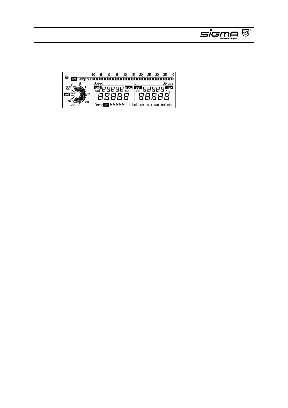
4.2 Displays
(Display completely active)
The display consists of the following areas:
- Time
- Symbol lock
- Temperature
- Speed
- RCF
- Rotor, Imbalance, run mode
4.2.1 Speed/RCF (Relative Centrifugal Force)
Rotor dimensions and speed determine the RCF value. Entry of one value
automatically determines the other one.
Operating Manual SIGMA 3-16K, page 43 of 69
03/06
Page 44
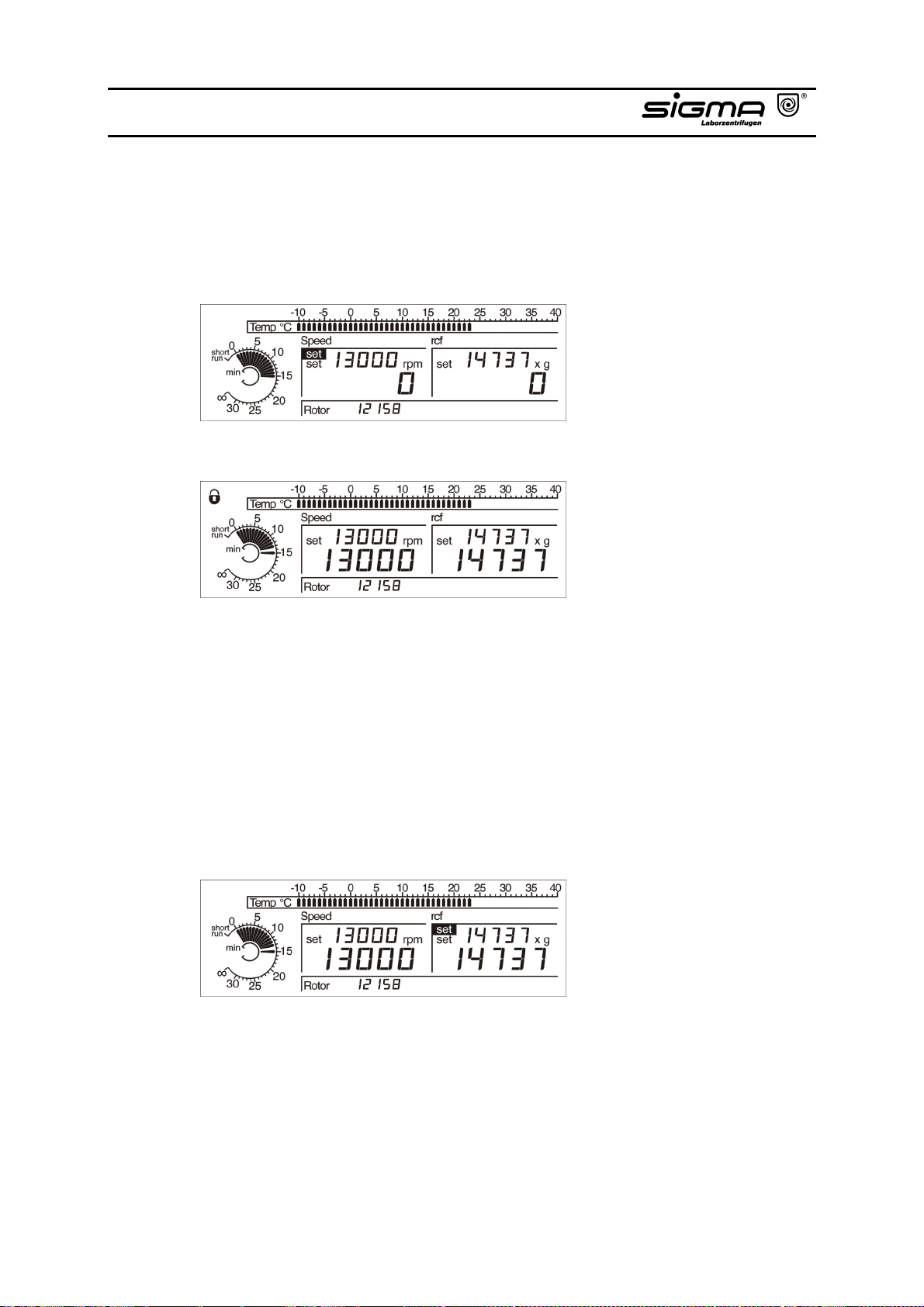
4.2.1.1 Speed
The display “Speed“ shows the rotations per minute. This value can be set by
turning the right knob. Preselection of 1 rpm by pressing and holding (2 – 3
seconds) the stop key.
The actual speed is displayed below the set value.
Activate “set“ in the “Speed“ area by turning the left knob. The speed value can
be changed during the run by turning the right knob.
4.2.1.2 Relative Centrifugal Force (RCF)
The relative centrifugal force (RCF) is the acceleration which the sample is
exposed to.
The display “rcf“ shows the rcf-value. Activate “set“ in the “rcf“ area with the left
knob. The rcf value can be changed by turning the right knob. This is also
possible when the centrifuge is running. Preselection of 1 x g by pressing and
holding (2 – 3 seconds) the stop key.
Please refer to chapter 1.2 “Suitable accessories“ for the maximum values for
the used rotor combination.
Operating Manual SIGMA 3-16K, page 44 of 69
03/06
Page 45
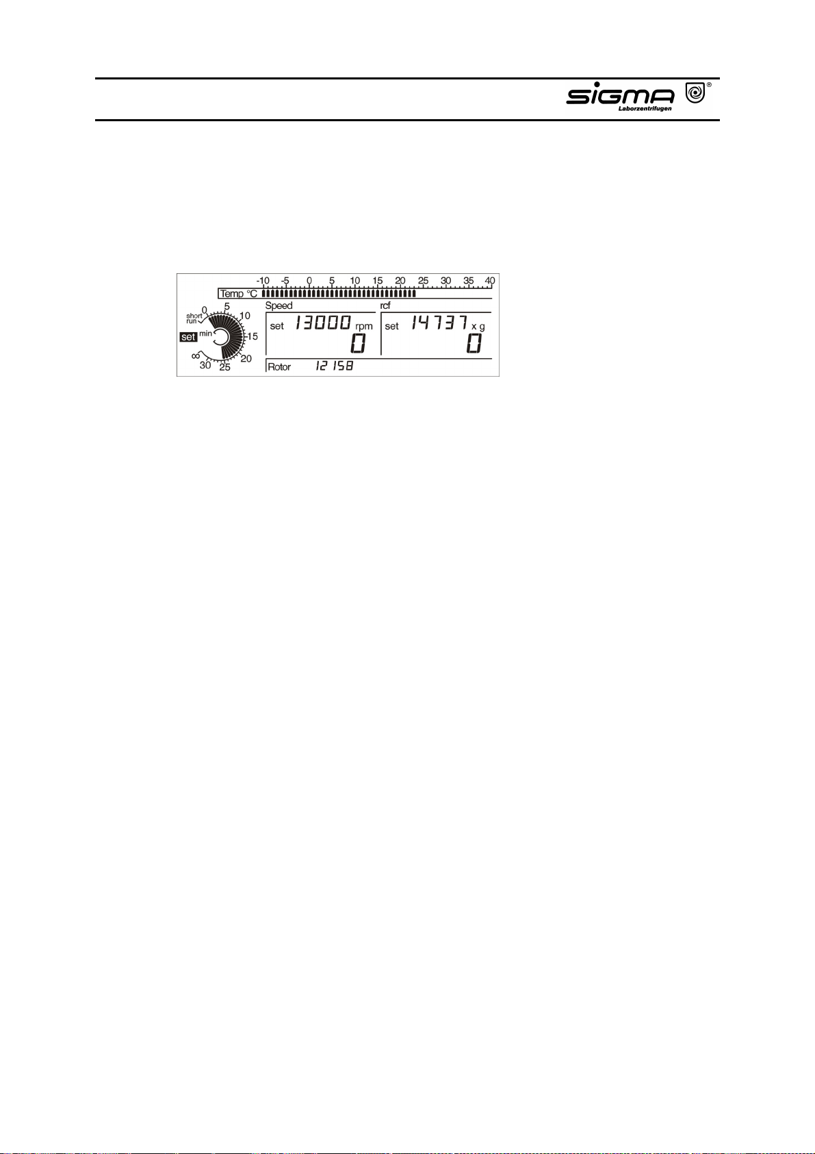
4.2.2 Time
This display shows the total set time, the remaining run time or the elapsed time.
The time value as well as different time modes can be set by turning the right
knob.
If the time is changed during centrifugation, the total newly entered period is run,
the
time elapsed before is not considered.
Operating Manual SIGMA 3-16K, page 45 of 69
03/06
Page 46
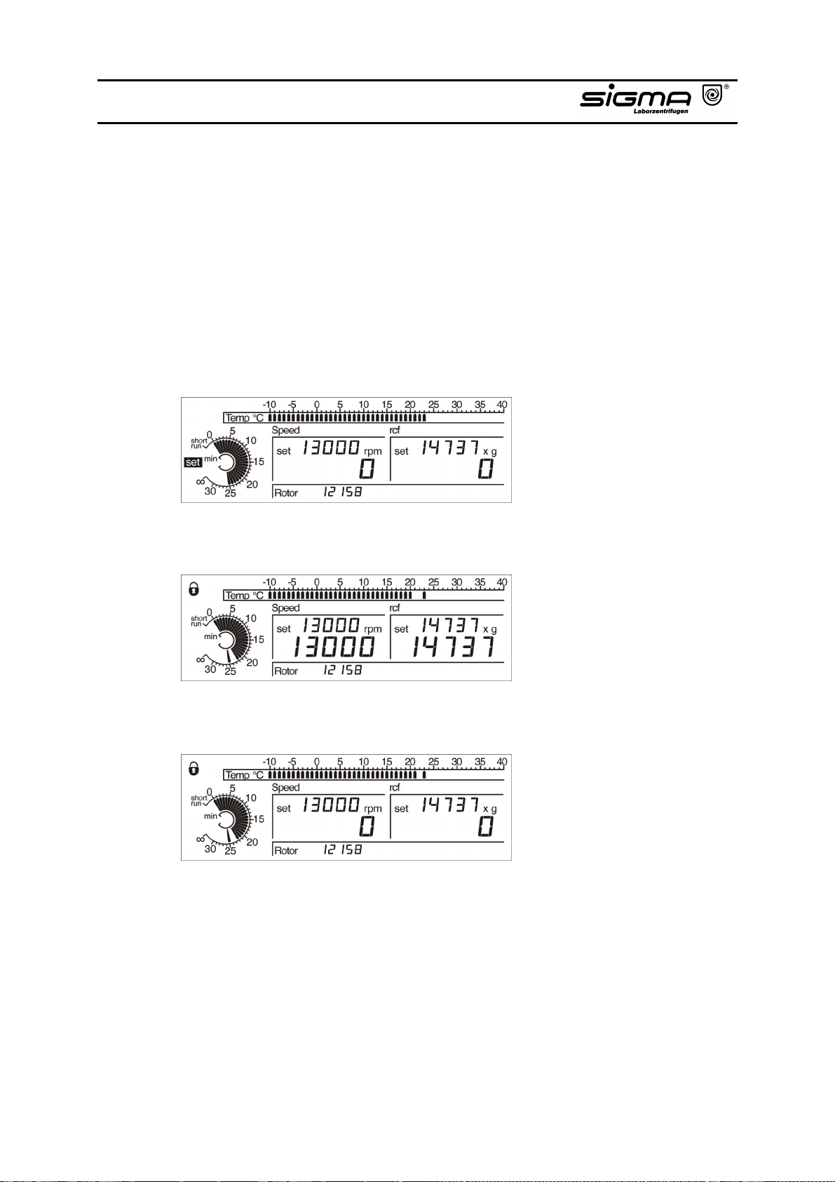
4.2.3 Standard Time Mode
For the standard time mode the time is set in minutes. Active “set“ in the time
area with the left knob. Enter the time by turning the right knob (the display shows
“min“).
This total run time (max. 30 minutes) is displayed by a sequence of bars before
starting the centrifuge.
During centrifugation this time is counted down, the sequence of bars indicates
the remaining run time. The set time is indicated by one single bar.
The centrifuge run can be early terminated by pressing the stop-key. The set time
and the remaining run time remain on the display.
Operating Manual SIGMA 3-16K, page 46 of 69
03/06
Page 47
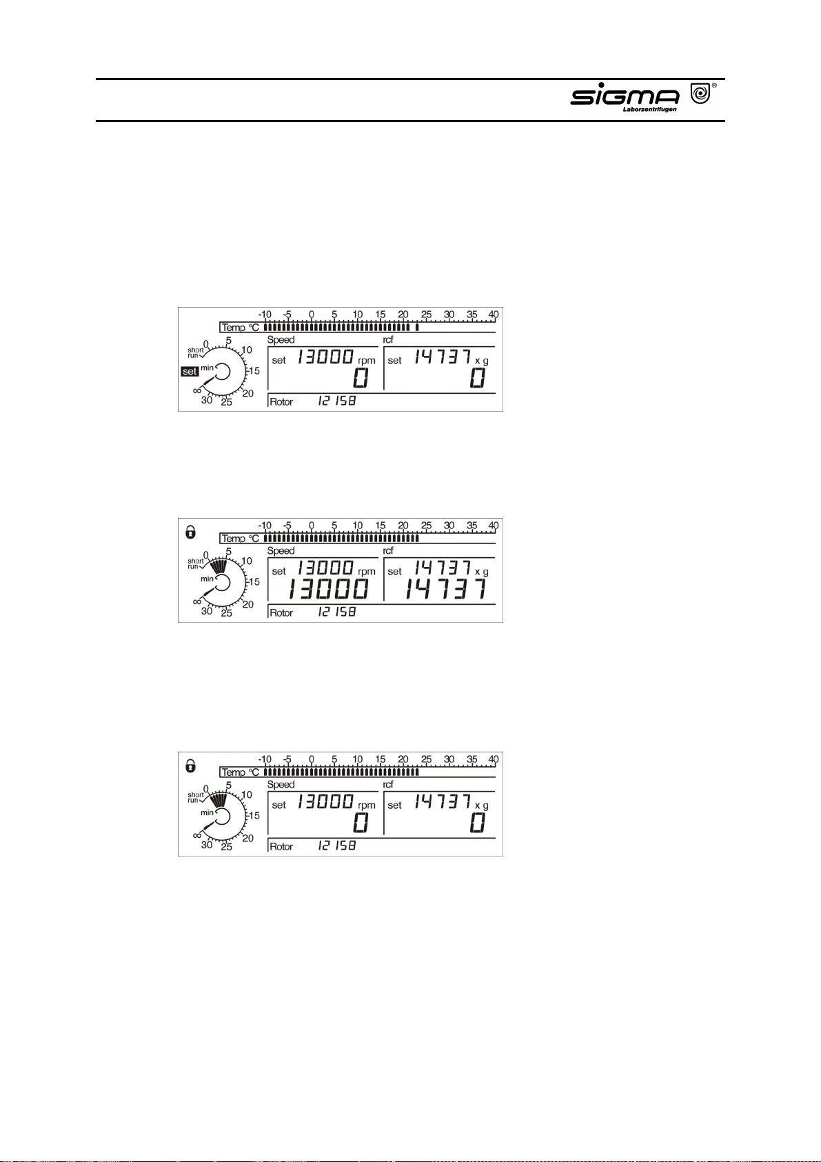
4.2.3.1 Continuous Operation Mode
During continuous run (∞) the centrifuge accelerates up to the set speed and the
run has to be terminated manually.
Activate “set“ in the time area using the left knob. Select ∞ by turning the right
knob and press the start-key to activate the continuous run.
Unlike the standard run mode the minutes are counted up. A sequence of bars
indicates the elapsed run time. One single bar at ∞ is indicating the continuous
run mode.
After 30 minutes the remaining run time is no longer displayed but the run
continues.
The continuous run is terminated by pressing the stop-key and the centrifuge
decelerates to a complete stop. The elapsed time is displayed in minutes.
The continuous run mode can be left by selecting a set value as well.
4.2.3.2 Short-Time Operation
There are two options:
Operating Manual SIGMA 3-16K, page 47 of 69
03/06
Page 48
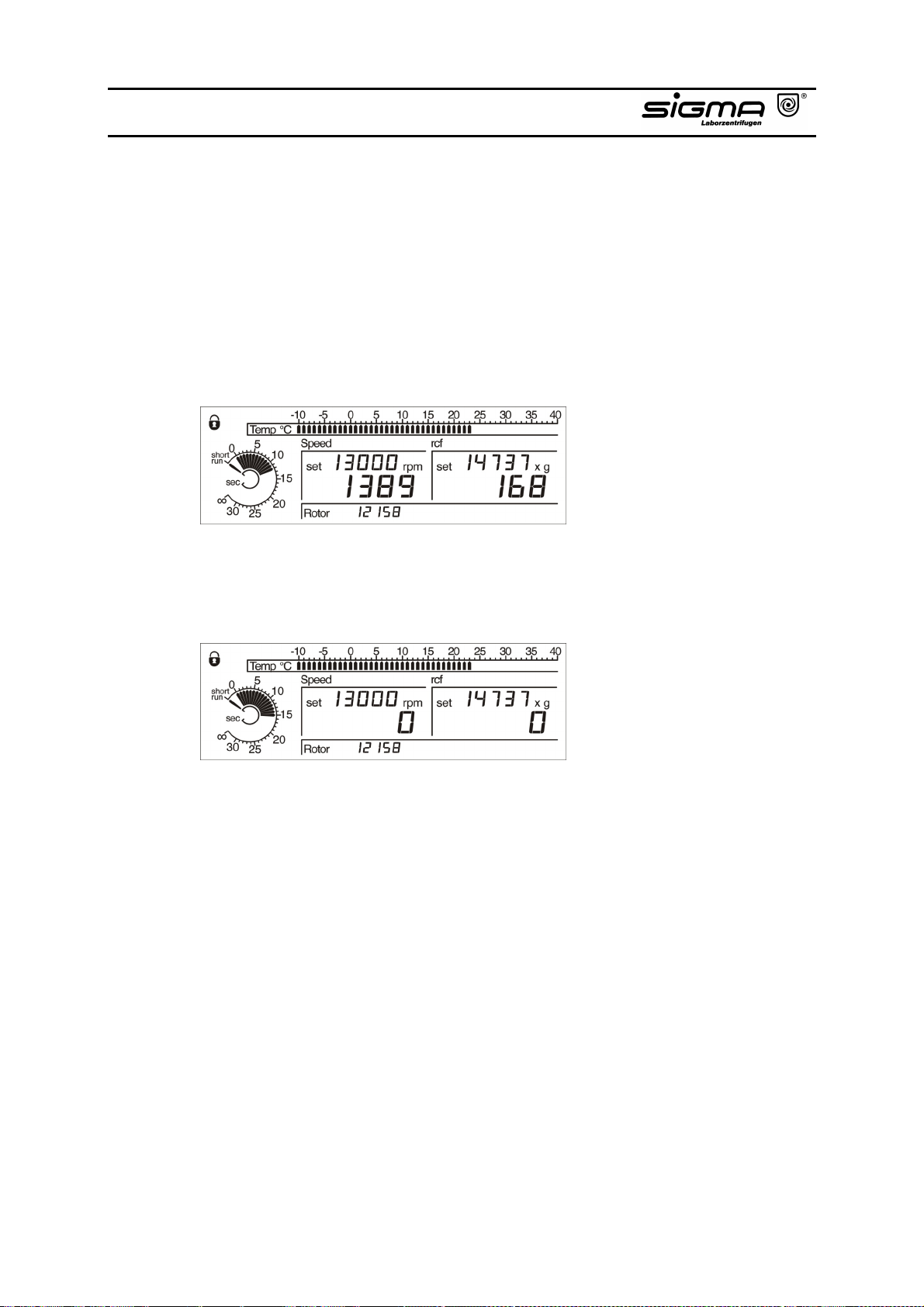
4.2.3.2.1 Short-Run 1
Press the start-key during the whole short-run. The centrifuge accelerates with
maximum power to the maximum speed. After release of the start-key the
centrifuge decelerates with maximum power to standstill.
During short-run the time is counted up in seconds, "sec" is displayed.
A sequence of bars is indicating the elapsed run time. One single bar at "short
run" indicates that short-time operation had been selected.
After termination of the short-run the elapsed run time in seconds remains on the
display.
Operating Manual SIGMA 3-16K, page 48 of 69
03/06
Page 49
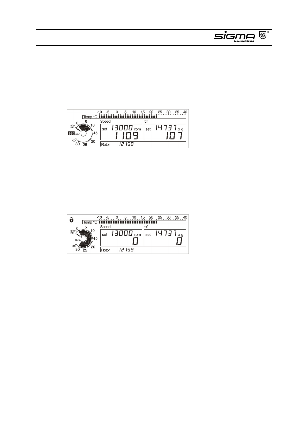
4.2.3.2.2 Short-Run 2
During this short-run the centrifuge is running max. 30 seconds and accelerates
to the set speed (rotor dependent).
Select "short run“ by turning the left knob and press the start-key.
During the short-run the time is counted up in seconds. A sequence of bars
indicates the elapsed run time. One single bar at "short run“ indicates that shorttime operation had been selected.
After 30 seconds the centrifuge decelerates to a complete stop.
The short-run can be early terminated by pressing the stop-key. The centrifuge
decelerates to standstill. The elapsed run time in seconds remains on the display.
The "short run“ can be left by selecting a set value as well.
Operating Manual SIGMA 3-16K, page 49 of 69
03/06
Page 50
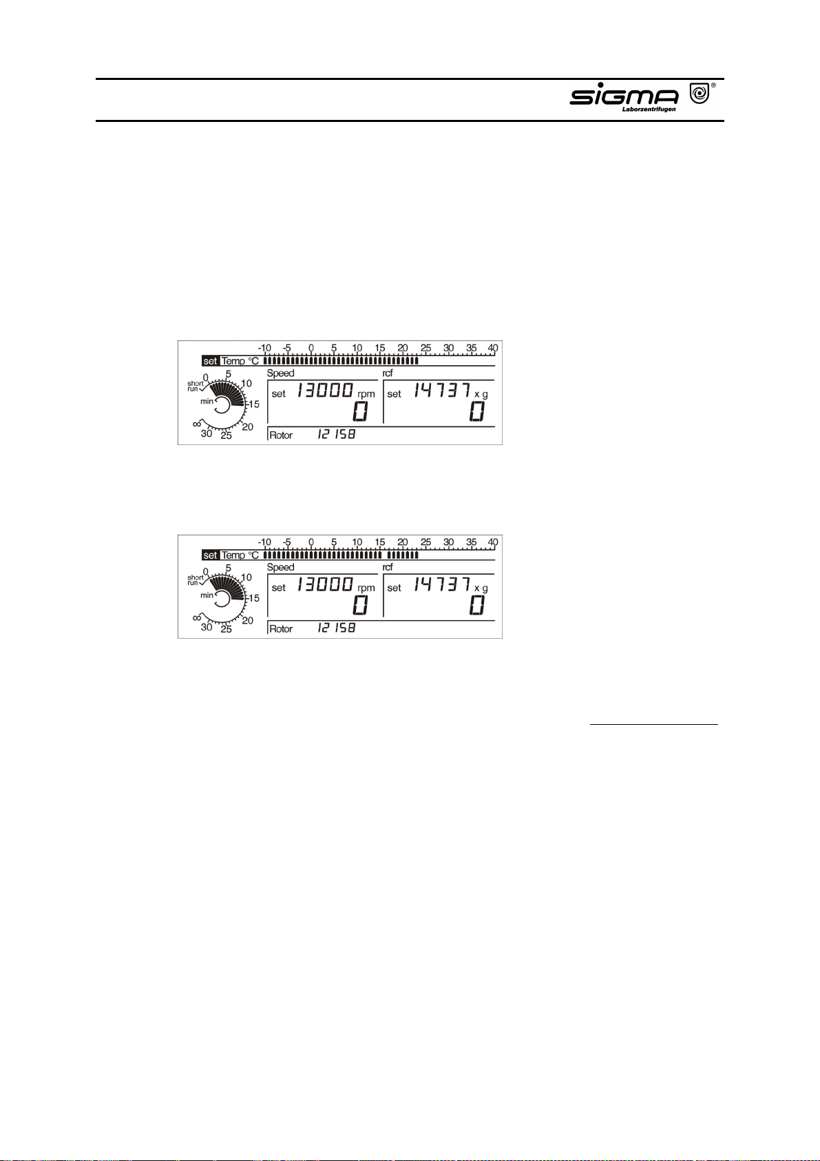
4.2.4 Temperature
The centrifuge is cooled with a cooling system. When a run is started, there is a
temperature difference between the sample and the rotor which is minimized
after a certain operating period has passed.
The scale of the upper display area shows the actual temperature in the
chamber. Activate “set“ in the temperature area using the left knob and select the
set value by turning the right knob. This is possible in steps of 1 °C.
Temperatures between – 10 °C and + 40 °C can be pre selected. If the set
temperature is lower than the actual temperature, the set value is indicated by a
flashing bar.
As soon as the lid is opened, the cooling system is disconnected in order to avoid
icing of the rotor chamber.
Precooling of the rotor below 0 °C during standstill is not recommended.
Differences between actual and displayed temperature and icing of the
compressor would be the result. This would reduce life of the compressor. We
recommend precooling at 5000 rpm.
The obtainable temperatures depend on rotor type, speed and ambient
temperature. (A change of the limit values might cause deviations.)
Operating Manual SIGMA 3-16K, page 50 of 69
03/06
Page 51
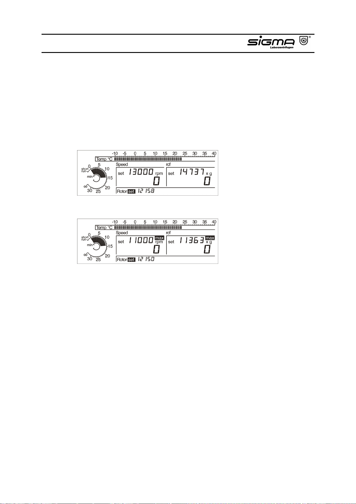
4.2.4 Preselection of a Rotor
The display “Rotor“ shows the preselected respectively the recognized rotor.
Activate “set“ in the “Rotor“ area using the left knob. An other rotor can be
selected by turning the right knob. This is not possible during a centrifuge run.
Attention: An automatic rotor identification occurs after the centrifuge has
been started. If the used rotor is not the same than the
preselected one, the used rotor is displayed and the
preselected speed is corrected.
Preselected rotor 12158
Changed to rotor 12150
Operating Manual SIGMA 3-16K, page 51 of 69
03/06
Page 52
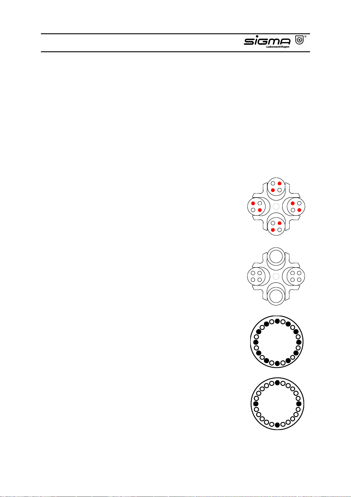
5.1 Practical Notes for Centrifugation
1. Locate centrifuge horizontally on a level surface.
2. Ensure safe location.
3. Keep at least 30 cm free space around the centrifuge.
4. Provide for sufficient ventilation.
5. Tighten rotor firmly onto motor shaft.
6. Avoid imbalance.
7. Load opposite buckets with same accessories.
8. Centrifugation with low capacity:
The example shows a complete swing out rotor 16 x 15 ml which is loaded with
8 vessels only. The vessels must be
loaded symmetrically so that the buckets
and their suspensions are loaded evenly.
Loading an eg. only an outer position of
the bucket is not allowed.
8.1Centrifugation with different tubes:
Working with different tube sizes is
possible. Opposite places must be
loaded with the same vessels.The
example shows a swing-out rotor with
buckets and 2 x carriers 100 ml and 2 x
carriers 4 x 15 ml with tubes.
8.2 Another example is the fixed angle rotor
24 x 2,2 ml:
The vessels should be placed symmetri-
cally so that the rotor is loaded evenly.
Loading e.g. only one position is not
allowed.
9. Load all positions of swing-out rotors.
10. Load vessels outside the centrifuge.
Operating Manual SIGMA 3-16K, page 52 of 69
03/06
Page 53

11. Please pay attention to the max. speed. At speeds over 4 000 rpm there is an
increased breaking glass hazard.
12. Fill vessels carefully to same weight. Imbalances would result in increased
wear of bearings.
13. Use perfect accessories only.
14. Avoid corrosion to accessories by careful maintenance.
15. Spin infectious material in sealed rotors and buckets only.
16. Do not spin explosive or highly imflammable materials.
17. When centrifuging substances with a density > 1,2 g/cm3 the allowable max.
speed must be reduced (refer to chapter 7.1.2 "Density").
18. Grease joints of buckets and rotor pins in swing-out rotors.
Operating Manual SIGMA 3-16K, page 53 of 69
03/06
Page 54

5.2 Forbidden Centrifuging Operations
1. Operation of not carefully installed centrifuge.
2. Operation without front or back panels.
3. Operation by non authorized personnel.
4. Operation with rotor not installed properly (refer to chapter 3.3).
5. Operation with incompletely loaded drum rotor, swing-out rotor or angle rotor
with interchangeable buckets.
A rotor must always be loaded completely, empty places are not allowed!
Opposite buckets or carriers may nevertheless be empty. Mixed loading is
allowed, if opposite places are loaded with same buckets and carriers of
same weight.
6. Operation with overloaded rotors.
The load for a rotor is limited by its design and the max. speed (see
rotor/bucket engraving) and must not be exceeded. The rotors are intended
for liquids of max. homogeneous density of 1.2 g/cm
speed. If liquids of higher density are used, the speed must be reduced
accordingly (refer to chapter 7.1 "Mathematical relations").
7. Operation with rotors and adapters showing corrosion or other defects.
8. Operation of very corrosive substances which can cause damages to material
and affect mechanical strength of rotors and adapters.
9. Operation of rotors and accessories not allowed by the manufacturer. The
use of poor commodity goods is not recommended. At high speeds breaking
glass or bursting vessels can cause dangerous imbalances.
10. Operation in hazardous locations.
11. Operation with vessels of improper size.
12. Centrifugation of improper material.
13. Operation with partially filled plastic tubes in high-speed angle rotors.
14. Lifting or moving of the centrifuge during operation. Leaning against or resting
on the centrifuge is not allowed.
15. Do not place potential dangerous material - e.g. glass vessels containing
liquids - near the centrifuge.
3
if centrifuged at max.
Operating Manual SIGMA 3-16K, page 54 of 69
03/06
Page 55

16. Attention:
Do not open cover and/or reach into rotor chamber unless the rotor is at
standstill. Never attempt to override the lid interlock system while the rotor is
spinning.
17. Such materials are prohibited which chemically interact vigorously.
18. Do not spin explosive or inflammable materials.
19. Substances which could damage the material of the centrifuge, the rotors or
the adapters must not be centrifuged. Infectious, toxic, pathogene or
radioactive substances must be centrifuged in certified rotors and vessels
only and all necessary safety precautions are taken.
Operating Manual SIGMA 3-16K, page 55 of 69
03/06
Page 56

6.1 Care and Cleaning of Centrifuge
Please use water-soluble, mild detergents for cleaning. Avoid corroding and
aggressive substances. Do not use alkaline solutions or solvents or agents with
abrasive particles. Before using detergents or decontamination agents which had
not been recommended by us, the user has to contact us to make sure that such
procedure would not damage the centrifuge.
Remove product particles from the rotor chamber using a cloth or paper towl. It is
recommended to open the cover when the centrifuge is not in use so that
moisture can evaporate. Increased wear of the motor bearings will thus be
avoided. If there is the risk of toxic, radioactive or pathogene
contamination, special safety measures must be kept.
6.2 Care and Cleaning of Accessories
For care of accessories special safety measures must be considered as these
are measures ensuring operational safety at the same time.
Buckets, trunnions and also synthetic buckets are produced exactly in order to
withstand the permanent high stress with high gravitational fields.
Chemical reactions as well as stress-corrosion (combination of oscillating pressure and chemical reaction) can affect or destroy the metals. Hardly detectable
cracks on the surface expand and weaken the material without visible signs.
When detecting a visible damage of the surface, a crack, a mark or any other
change, also corrosion, the part (rotor, etc.) must be replaced immediately.
In order to avoid corrosion, rotor incl. tie-down screw and cover seal and
adapters must be cleaned and greased regularly with the supplied slushing oil
(Sigma part no.: 70104 for 20 ml slushing oil). Before using detergents or
decontamination agents which had not been recommended by us, the user has
to contact us to make sure that such procedure would not damage the centrifuge.
The rotor tie-down screw must be greased using grease (Sigma part no.: 70284).
Cleaning of accessories should be done outside of the centrifuge once a week or
preferably after every use. Adapters should be removed. After this the parts
should be dried with a soft cloth or, alternatively, in a drying chamber at approx.
50 °C. If there is the risk of toxic, radioactive or pathogene contamination,
special safety measures must be kept.
Especially aluminium parts are extremely corrosive. A neutral cleaning detergent
with a pH-value between 6 and 8 should be used for such parts. Alkaline agents
exceeding pH 8 must be avoided. Especially aluminium parts must be greased
regularly with slushing oil. This procedure essentially increases life time and
reduces corrosion.
Careful maintenance increases life time and avoids premature failure of the rotor.
Corrosion or resultant damages which are caused by insufficient care do not
constitute a warranty claim.
Operating Manual SIGMA 3-16K, page 56 of 69
03/06
Page 57

6.3 Rotor Pins
The trunnion pins of the rotor should always be greased as only this ensures
evenly swinging of buckets and thus quiet run of the centrifuge (part no. 70284
Grease).
6.4 Glass Breakage
In case of glass breakage all glass particles must be carefully removed. Rubber
inserts have to be cleaned carefully and possibly be replaced. If a problem has
occured, the following has to be considered:
Glass particles in the rubber cushion will cause glass breakage again.
Glass particles in the centrifuge chamber will cause metal abrasion due to the
strong air circulation. This dust will not only pollute the centrifuge chamber, the
rotor and the material to be centrifuged but also damage the surfaces of the
accessories, the rotors and the centrifuge chamber.
In order to totally remove the glass particles and the metal dust from the rotor
chamber, it is advisable to grease the upper part of the centrifuge chamber with
e.g. Vaseline. Then the rotor should rotate for some minutes at a moderate
speed. The glass and metal particles will now collect at the greased part and can
easily be removed with a cloth together with the grease. If necessary repeat this
procedure.
6.5 Care and Cleaning of the Condenser
A lamellar condenser is used to cool the compressed refrigerant. It is installed in
the back part of the centrifuge and cooled with air.
The location for the centrifuge should therefore be as clean as possible, ie. dirt,
dust etc. should not prevent the air from streaming through the condenser and
obstruct heat transfer. Dust on the condenser pipes and the lamella will reduce
heat exchange and decrease the performance of the refrigerator.
The condenser should therefore be regularly checked for dirt and cleaned if
necessary. Generally blowing of the lamella with compressed air from inside and
outside is sufficient (or a simple hoovering with a vacuum cleaner).
Operating Manual SIGMA 3-16K, page 57 of 69
03/06
Page 58

6.6 Sterilization and Disinfection of Rotor Chamber and
Accessories
All usual disinfectants like eg. Sagrotan, Buraton or Terralin (to obtain at
chemist’s shops) can be used. The centrifuges and the accessories consist of
different materials. A possible incompatibility must be considered. Before using
detergents or decontamination agents which had not been recommended by us,
the user has to contact us to make sure that such procedure would not damage
the centrifuge. For sterilization by steam resistance to temperature of the
individual material must be checked (refer to point 6.6.1 “Autoclaving“). Please
contact your laboratory safety officer regarding proper methods to use. If
dangerous materials are used, the centrifuge and the accessories must be
disinfected.
Principally we want to point out that for centrifuging of e.g. infectious material
certified and hermetically sealed accessories have to be used in order to avoid
that the centrifuge is contaminated.
Operating Manual SIGMA 3-16K, page 58 of 69
03/06
Page 59
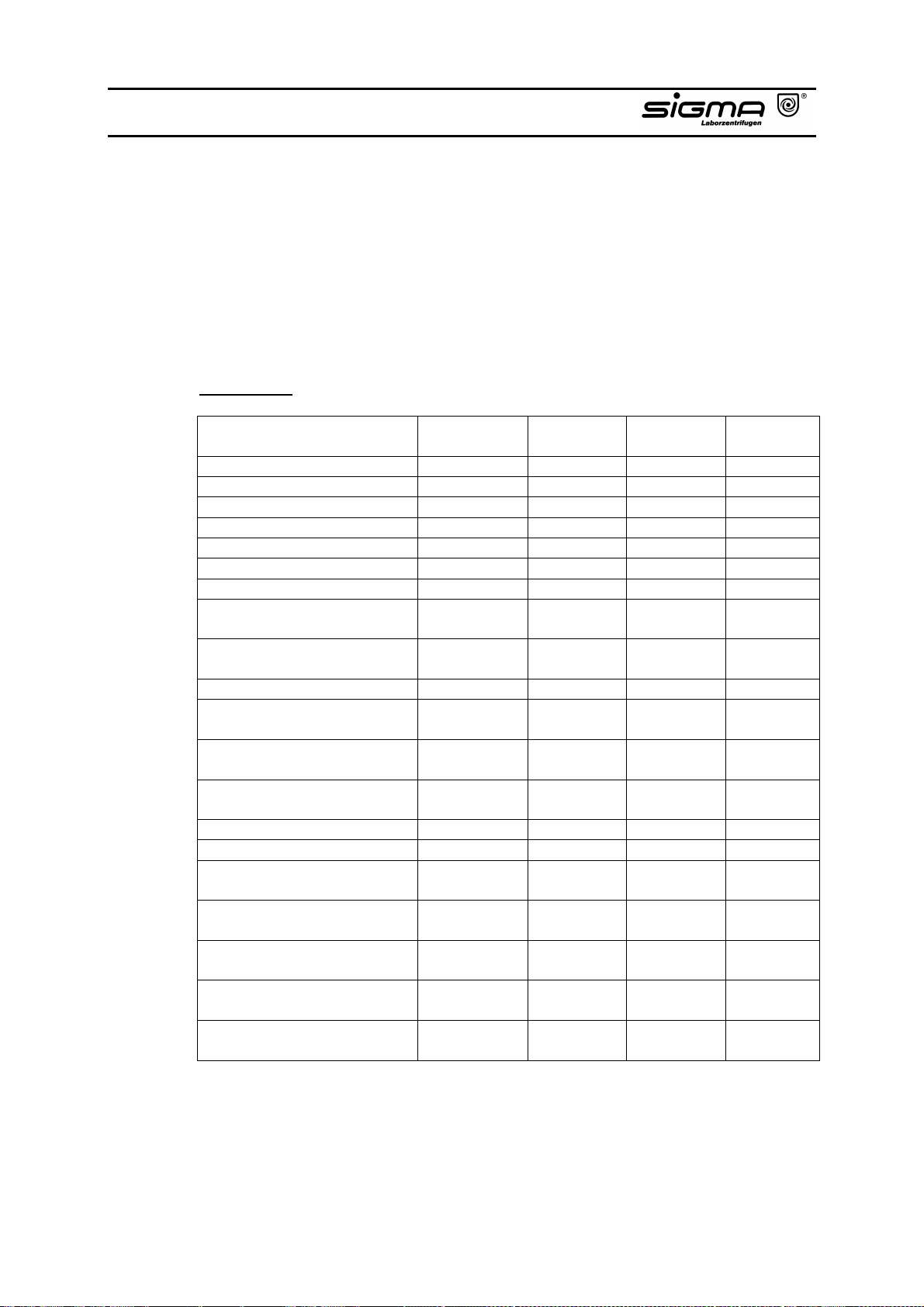
6.6.1 Autoclaving
The life of the accessories essentially depends on the frequency of autoclaving
and use. When the parts are showing changes in colour or structure or in the
event of leaks etc., the accessories have to be replaced.
During autoclaving the caps of the tubes must not be screwed on to avoid
deformation of the tubes. It can not be excluded that plastic parts, e.g. lids or
carriers, would deform during autoclaving.
Autoclaving:
Accessories max. temp.
Glass tubes 134-138 3 5 -
Polycarbonate tubes 115-118 30 40 20
Polypropylene tubes 115-118 30 40 30
Teflon tubes 134-138 3 5 100
Aluminium rotors 134-138 3 5 Polypropylene rotor 12034 115-118 30 40 20
Polypropylene rotor 12124 115-118 30 40 20
Polycarbonate/Polyallomer
lids for angle rotors
Polysulfone lids for angle
rotors
Aluminium buckets 134-138 3 5 Polycarbonate caps for
buckets
Polypropylene caps for
buckets
Polysulfone caps for
buckets
Rubber adapters 115-118 30 40 Rubber cushions 115-118 30 40 Round carriers for 13104/
13117, Polypropylene
ditto, Polyallomer and
Polycarbonate
Round carriers for 13350/
13550, Polypropylene
Rectangular carriers,
Polypropylene
ditto, Polyallomer and
Polycarbonate
min. time
°C
115-118 30 40 20
134-138 3 5 100
115-118 30 40 50
115-118 30 40 50
134-138 3 5 100
115-118 30 40 115-118 30 40 115-118 30 40 115-118 30 40 115-118 30 40 -
min
max. time
min
max.
cycles
Operating Manual SIGMA 3-16K, page 59 of 69
03/06
Page 60

6.7 Checks by Operator
The operator has to ensure that no important part of the centrifuge is damaged.
This especially refers to:
1. Motor suspension
2. Concentricity of the motor shaft
3. Fastening of the trunnions in the rotor
4. Rotors and accessories have a limited life. For safety reasons a regular
check is recommended after 50.000 cycles. Any changes like e.g. corrosion,
cracks, material abrasion etc. require special attention.
5. Screw connections have to be tight.
Furthermore, the earth wire must be checked regularly.
Operating Manual SIGMA 3-16K, page 60 of 69
03/06
Page 61

7.1 Mathematical Relations
7.1.1 Relative Centrifugal Force (RCF)
The parameters speed, RCF and the diameter of the rotor are interrelated via the
following formula:
RCF = 11,18 x 10⁻⁶ x r x n2
If two values are given, the third value is determined by the equation. If the speed
or the rotation radius is changed, the resulting RCF will be recalculated. If the
RCF is changed, the speed under consideration of the radius is adapted
accordingly.
r = radius in cm
n = speed in rpm
RCF without dimension
7.1.2 Density
If the density of the liquid is higher than 1.2 g/cm3, the allowed maximum speed
of the centrifuge is reduced according to the following formula:
n = n
Rho = density in g/cm3
max
x
)/2,1( Rho
Operating Manual SIGMA 3-16K, page 61 of 69
03/06
Page 62

7.2 Error Correction
Most of the errors can be reset by power off/on. In the event of a short power
failure during a run, this run is interrupted and can be continued by pressing the
Start-key.
No indication on the display: Actions:
− No power in the socket?
− Power cord plugged in and line
voltage present?
− Power switch on?
− Lid closed?
• Check fuse in mains supply.
• Plug in power cord correctly.
• Switch on power.
• Close lid (please refer to chapter 7.2.3 „Lid
cannot be opened/closed.“).
7.2.1 Centrifuge cannot be Started
− Start-key LED illuminated: • Power off/on. If error occurs again, call
service.
− Lid-key LED flashing: • Open and close the lid again. If error
occurs again although the lock engaged,
call service.
7.2.2 Centrifuge Decelerates during Operation
− Centrifuge displays an error 1
to 11 after power on.
• Power off/on. If error occurs again, call
service (please refer to chapter 7.3.1
"Error codes").
7.2.3 Lid cannot be Opened/Closed
− When first trying to open the lid the lock is not released. The Lid-key LED is
flashing. Open and close lid again.
Operating Manual SIGMA 3-16K, page 62 of 69
03/06
Page 63
7.2.4 Emergency Lid Release
At the upper right panel there is a stopper which can be removed eg. with a
screw driver. The lid can be released by pulling the visible string.
Attention!
The lid may only be unlocked and opened when the rotor is at standstill.
7.2.5 Problems with the Centrifuge?
Please contact your supplier for support or in the event of malfunctions and for
supply of spare parts.
7.3 Error Mode
In the error mode the Start-, Stop- and Lid-keys are flashing. “ERROR“ is
displayed in the speed area and the error code in the rcf area.
7.3.1 Error Codes
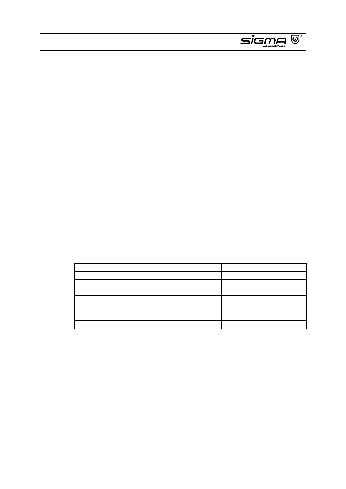
Error no. Kind of error Actions
1 Tacho signal disturbed
4 Lid does not open after
pressing the Lid-key
2, 3, 5 – 11, 17 - 30 Internal fault
12 Imbalance determined
13 Temperature sensor
14 Excess temperature (>50°C)
Should it not be possible to repair the failure, please contact Service!
7.4 Speed-RCF-Diagram
An additional help is the enclosed Speed-RCF-Diagram.
• Power off/on
• Power off/on
• Emergency lid release
• Power off/on
• Remove imbalance
• Contact service
• Let centrifuge cool down
Operating Manual SIGMA 3-16K, page 63 of 69
03/06
Page 64

7.5 Declaration of Decontamination / Return Declaration
The following declarations serve for keeping safety and health of our employees.
Fill in the forms and attach them when returning centrifuges, accessories and
spare parts. Please understand that we cannot carry out any work before we
have the declarations. (We recommend to make several copies of this page.)
Operating Manual SIGMA 3-16K, page 64 of 69
03/06
Page 65
----------------------------------------------------------------------------------------------------------------------
Decontamination declaration inside :
Unit / component contaminated :
Unit / component unused (new) :
---------------------------------------------------------------------------------------------------------------------Please make some copies before removing this page.
!!! Attention – This form must be glued on outside of the box !!!
Return declaration
YES NO
!!! Attention – This form must be glued on outside of the box !!!
Operating Manual SIGMA 3-16K, page 65 of 69
03/06
Page 66

Page 67
----------------------------------------------------------------------------------------------------------------------
Declaration of Decontamination of Centrifuges, Accessories and Spare Parts
This declaration may only be filled in and signed by authorised staff.
Repair Order dtd. :
Order No. :
Type of unit : Serial No. :
Type of unit : Serial No. :
Type of unit : Serial No. :
Type of unit : Serial No. :
Accessories :
Is the equipment free from harmful substances ? YES Ο NO Ο
If not, which substances have come into contact with the equipment?
Name of the substances : _________________________________________________________________
_________________________________________________________________
Remarks (e.g to be touched _________________________________________________________________
with gloves only) : _________________________________________________________________
General characteristics of the substances :
Corrosive Ο Explosive Ο
Biologically hazardous Ο Radioactive Ο
Toxic Ο
In combination with which substances may hazardous mixtures develop?
Name of the substances :
Has the equipment been cleaned before shipment? YES Ο NO Ο
Is the equipment decontaminated and not harmful to health? YES Ο NO Ο
Prior to repair, radioactively contaminated components must be decontaminated according to the valid
regulations for radiation protection.
Legally Binding Declaration
I / we hereby declare that the information on this declaration are correct and complete.
Company / Institute :
Street :
Postcode, City :
Tel. : FAX :
Name :
Date : Stamp :
Signature :
---------------------------------------------------------------------------------------------------------------------Please make some copies before removing this page.
Operating Manual SIGMA 3-16K, page 67 of 69
03/06
Page 68

Page 69
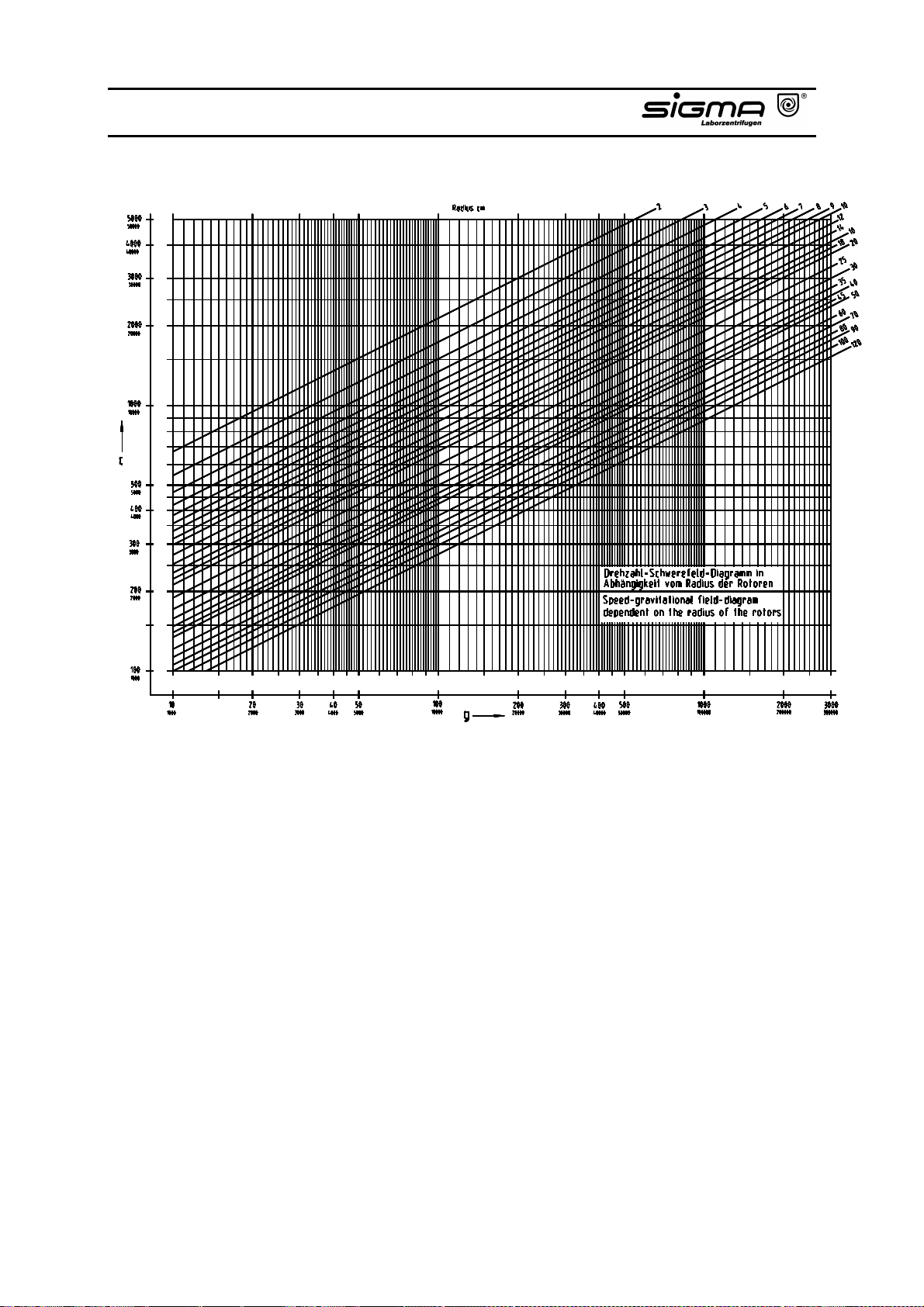
Operating Manual SIGMA 3-16K, page 69 of 69
03/06
 Loading...