

Page 1
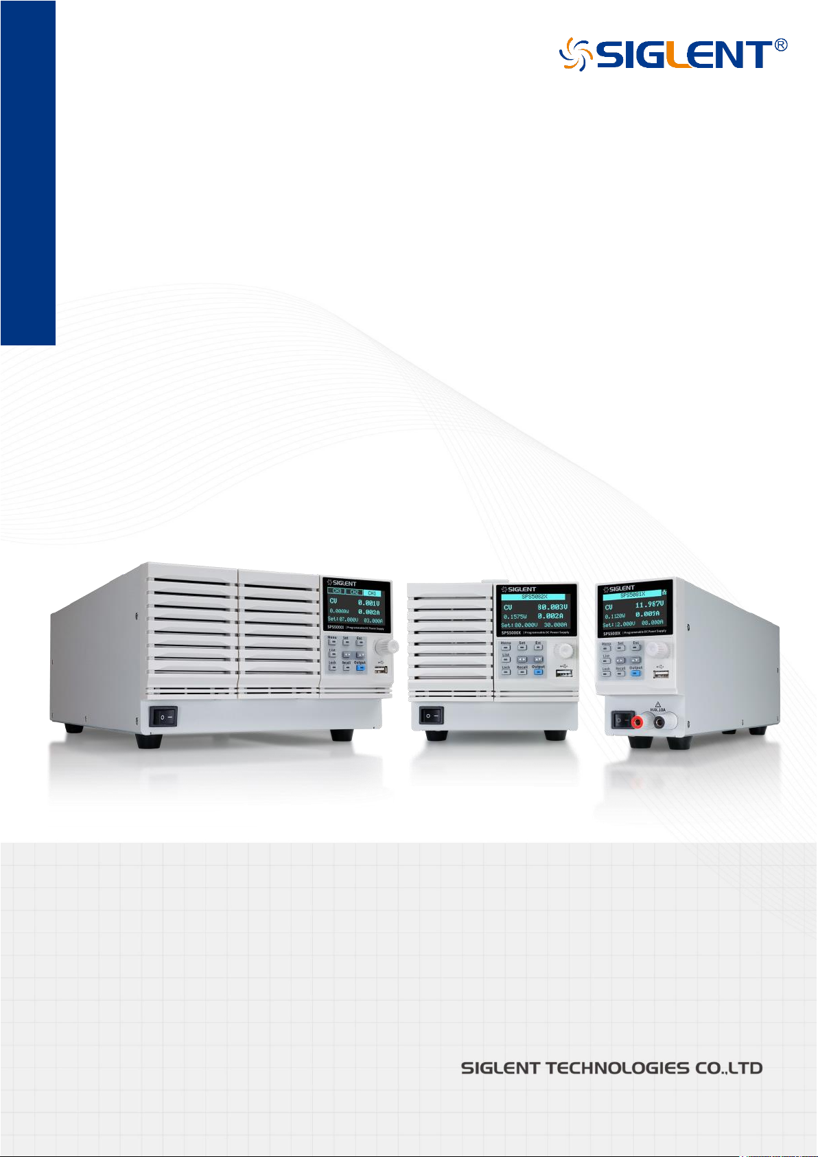
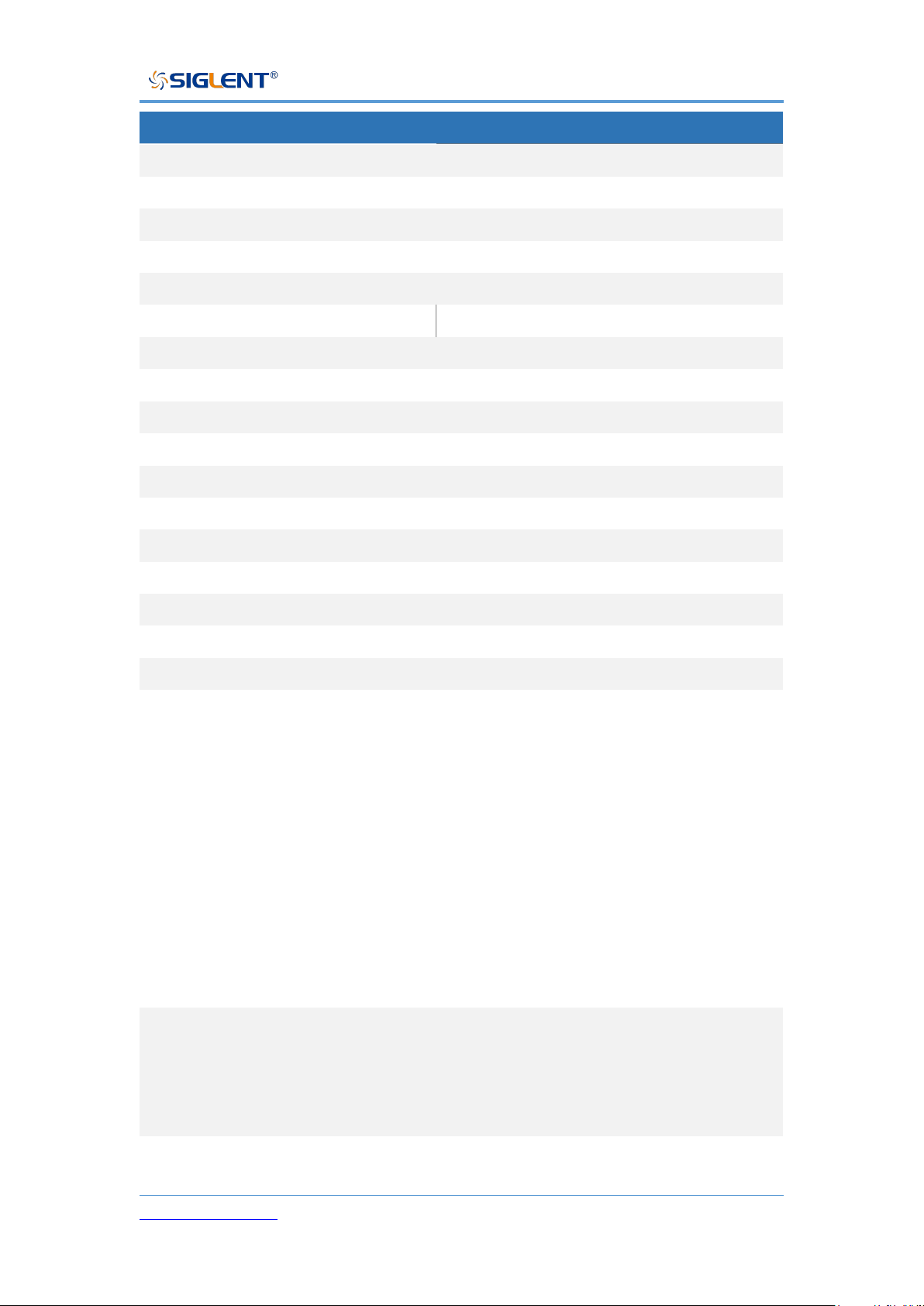
SPS5000X Series User Manual
WWW.SIGLENT.COM 0
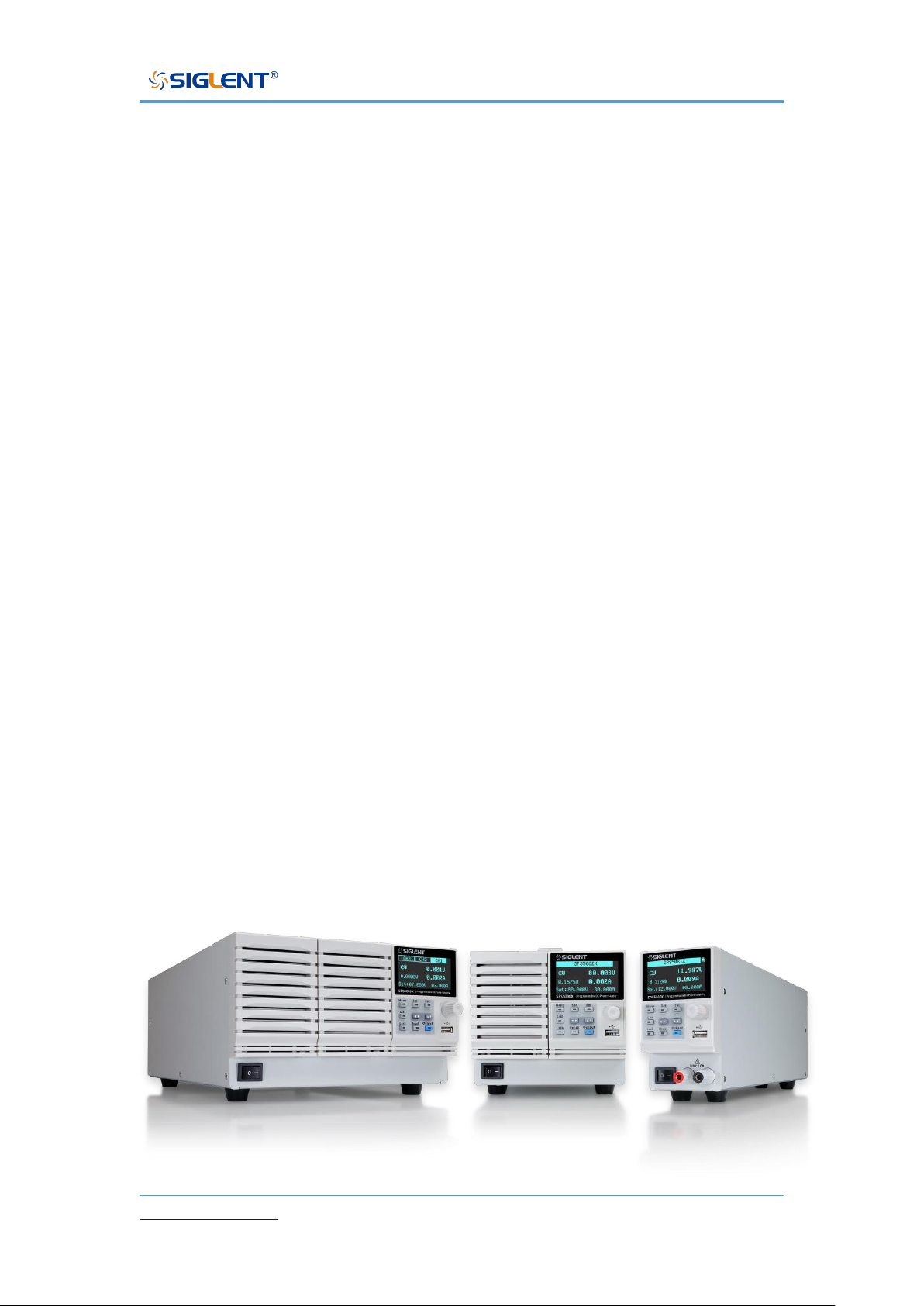
SPS5000X Series
Wide Range Programmable
Switching DC Power Supplies
User Manual
Page 2

SPS5000X Series User Manual
WWW.SIGLENT.COM 1
Contents
INTRODUCTION ...................................................................................................................................... 4
IMPORTANT SAFETY INFORMATION ................................................................................................... 5
GENERAL SAFETY SUMMARY .................................................................................................................... 5
SAFETY TERMS AND SYMBOLS .................................................................................................................. 6
WORKING ENVIRONMENT .......................................................................................................................... 7
COOLING REQUIREMENTS ......................................................................................................................... 9
AC POWER AND GROUND CONNECTIONS .................................................................................................... 9
CLEANING ............................................................................................................................................ 10
ABNORMAL CONDITIONS ........................................................................................................................ 11
INFORMATIONS ESSENTIELLES SUR LA SÉCURITÉ ...................................................................... 13
EXIGENCE DE SÉCURITÉ ........................................................................................................................ 13
TERMES ET SYMBOLES DE SÉCURITÉ ....................................................................................................... 15
ENVIRONNEMENT DE TRAVAIL ................................................................................................................. 15
EXIGENCES DE REFROIDISSEMENT .......................................................................................................... 17
CONNEXIONS D'ALIMENTATION ET DE TERRE ............................................................................................ 18
NETTOYAGE ......................................................................................................................................... 19
CONDITIONS ANORMALES ....................................................................................................................... 20
DELIVERY OF THE POWER SUPPLY ................................................................................................. 21
GENERAL INSPECTION ........................................................................................................................... 21
ABOUT WARRANTY ............................................................................................................................... 22
MAINTENANCE AGREEMENT ................................................................................................................... 23
INTRODUCTION OF SPS5000X SERIES ............................................................................................. 24
PERFORMANCE AND FEATURES .............................................................................................................. 25
MODEL INTRODUCTION .......................................................................................................................... 26
SPS5000X SERIES OVERVIEW ........................................................................................................... 27
APPEARANCE ....................................................................................................................................... 27
REAR PANEL ........................................................................................................................................ 29
THEORY OF OPERATION .................................................................................................................... 32
OPERATING AREA DESCRIPTION ............................................................................................................. 32
CC AND CV MODE ................................................................................................................................ 33
SLEW RATE .......................................................................................................................................... 34
BLEEDER CONTROL .............................................................................................................................. 34
INTERNAL RESISTANCE .......................................................................................................................... 35
ALARMS ............................................................................................................................................... 36
CONSIDERATIONS .................................................................................................................................. 37
Inrush current
........................................................................................................................................................ 37
Pulsed or Peaked loads
...................................................................................................................................... 38
Page 3

SPS5000X Series User Manual
WWW.SIGLENT.COM 2
Reverse current regenerative load
................................................................................................................... 38
Reverse current connection method
................................................................................................................ 38
Grounding
.............................................................................................................................................................. 39
SWITCH ON / OFF AND OUTPUT PORT ............................................................................................. 41
CONNECT THE POWER CORD ................................................................................................................. 41
POWER ON ........................................................................................................................................... 41
POWER OFF ......................................................................................................................................... 42
OUTPUT PORT ...................................................................................................................................... 43
USER INTERFACE................................................................................................................................ 44
BASIC OPERATION.............................................................................................................................. 47
SYSTEM SETTINGS ................................................................................................................................ 47
View Version Information
................................................................................................................................... 47
System Upgrade
................................................................................................................................................... 47
Restore Default
..................................................................................................................................................... 48
Beeper Setup
........................................................................................................................................................ 48
Parallel/Series Operation
................................................................................................................................... 48
FUNCTION SETTINGS ............................................................................................................................. 52
Set List Function
................................................................................................................................................... 52
Set OCP/OVP
....................................................................................................................................................... 54
Set Bleeder Control
............................................................................................................................................. 54
Set CC/CV Priority
............................................................................................................................................... 55
Set Ouput On/Off Delay Time
........................................................................................................................... 56
Set Internal Resistance
....................................................................................................................................... 56
Set Measurement Verage
.................................................................................................................................. 57
External Analog Control
...................................................................................................................................... 57
External Control Output On/Off
......................................................................................................................... 59
Multi-channel Settings
......................................................................................................................................... 60
Analog Interface
................................................................................................................................................... 61
Communication interface settings
.................................................................................................................... 63
REMOTE CONTROL ............................................................................................................................. 65
WAY TO CONTROL ................................................................................................................................ 65
GRAMMATICAL CONVENTIONS ................................................................................................................ 66
COMMAND SUMMARY ............................................................................................................................ 67
COMMAND DESCRIPTION ..................................................................................................................... 68
IEEE Common Command Subsystem
............................................................................................................ 68
Measure Command Subsystem
....................................................................................................................... 70
Configure Configuration Command Subsystem
........................................................................................... 72
List Configuration Command Subsystem
....................................................................................................... 79
System Configuration Command Subsystem
................................................................................................ 82
WEB SERVICE ....................................................................................................................................... 86
TROUBLESHOOTING........................................................................................................................... 91
Page 4

SPS5000X Series User Manual
WWW.SIGLENT.COM 3
CONTACT US ....................................................................................................................................... 93
Page 5
SPS5000X Series User Manual
WWW.SIGLENT.COM 4
Introduction
This user manual includes important safety and installation information related
to the SPS5000X series wide range programmable Switching DC Power
Supply and includes simple tutorials for basic operation of the supply.
The series includes the following models:
Model
Output parameters
SPS5041X
40 V/30 A/360 W
SPS5042X
40 V/60 A/720 W
SPS5043X
40 V/90 A/1080 W
SPS5044X
2-channel, 40 V/30 A/360 W/CH
SPS5045X
3-channel, 40 V/30 A/360 W/CH
SPS5051X
50 V/10 A/180 W
SPS5081X
80 V/15 A/360 W
SPS5082X
80 V/30 A/720 W
SPS5083X
80 V/45 A/1080 W
SPS5084X
2-channel, 80 V/15 A/360 W/CH
SPS5085X
3-channel, 80 V/15 A/360 W/CH
SPS5161X
160 V/7.5 A/360 W
SPS5162X
160 V/15 A/720 W
SPS5163X
160 V/22.5 A/1080 W
SPS5164X
2-channel, 160 V/7.5 A/360 W/CH
SPS5165X
3-channel, 160 V/7.5 A/360 W/CH
Page 6

SPS5000X Series User Manual
WWW.SIGLENT.COM 5
Important Safety Information
This manual contains information and warnings that must be followed by the
user for safe operation and to keep the product in a safe condition.
General Safety Summary
Carefully read the following safety precautions to avoid personal injury and
prevent damage to the instrument and any products connected to it. To avoid
potential hazards, please use the instrument as specified.
To avoid fire or personal injury, use the proper power cord.
Only use the state/locally approved power cord with the instrument.
Ground the instrument.
The instrument grounds through the protective terra conductor of the power
line. To avoid electric shock, the ground conductor must be connected to the
earth. Make sure the instrument is grounded correctly before connect its input
or output terminals.
Review all terminal ratings before use.
To avoid fire or electrical shock, please look over all ratings and instructions
for the instrument. Before connecting the instrument, please read the manual
carefully to gain more information about the ratings and important use
instructions for safe operation.
Do not operate with suspected failures.
If you suspect that there is damage to the instrument, halt use and contact your
Page 7
SPS5000X Series User Manual
WWW.SIGLENT.COM 6
local SIGLENT dealer immediately.
Do not operate in wet/damp conditions.
Do not operate in an explosive atmosphere.
Keep the surface of the instrument clean and dry.
Anyone operating this equipment should refer to the instruction manual
to understand the protection afforded by the equipment. Please use the
instrument only in accordance with regulations.
Safety Terms and Symbols
When the following symbols or terms appear on the front or rear panel of the
instrument or in this manual, they indicate special care in terms of safety.
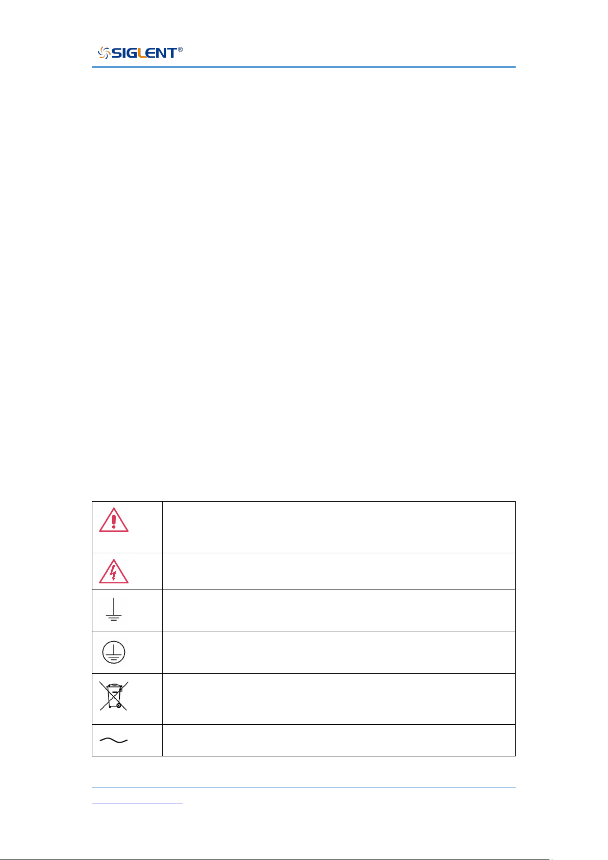
This symbol is used where caution is required. Refer to the
accompanying information or documents to protect against personal
injury or damage to the instrument.
This symbol warns of a potential risk of shock hazard.
This symbol is used to denote the measurement ground connection.
This symbol is used to denote a safety ground connection.
This symbol shows that do not put electronic equipment as unsorted
municipal waste management. Please separate collection or contact
equipment suppliers.
This symbol is used to represent an alternating current, or "AC".
Page 8
SPS5000X Series User Manual
WWW.SIGLENT.COM 7
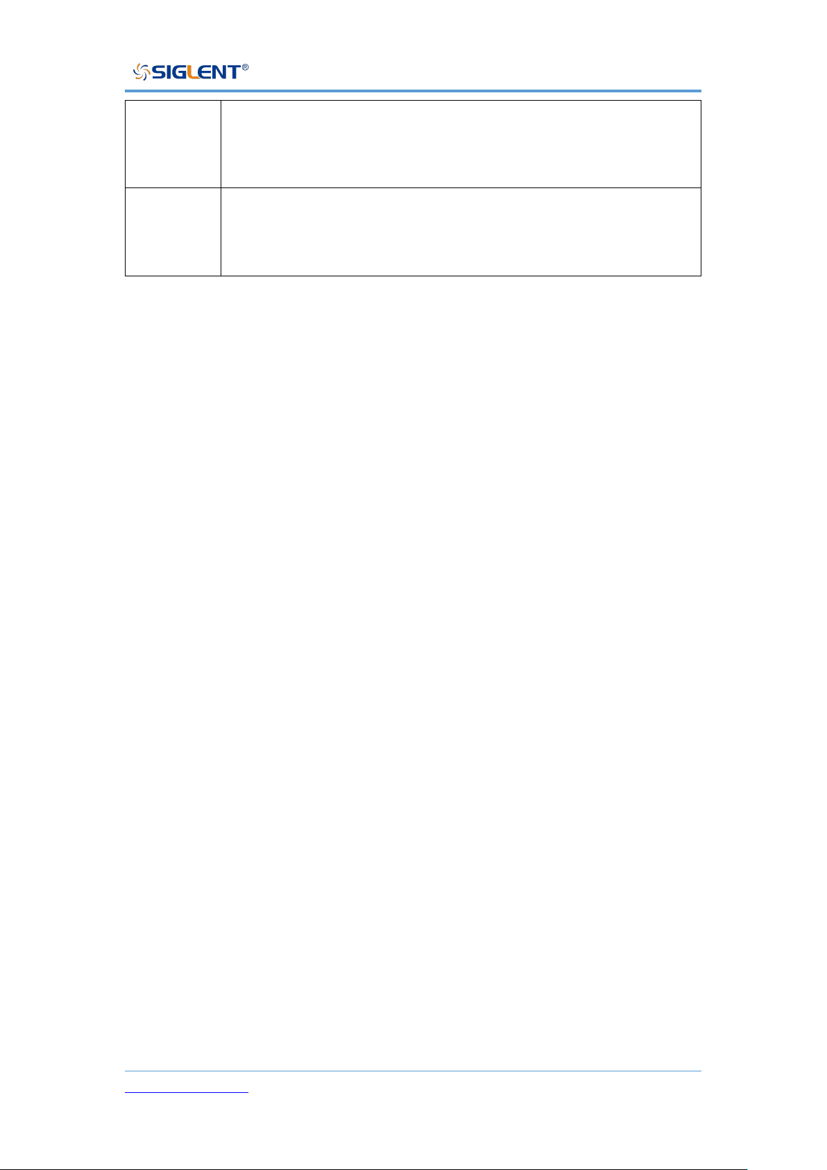
CAUTION
The "CAUTION" symbol indicates a potential hazard. It calls
attention to a procedure, practice, or condition which may be
dangerous if not followed. Do not proceed until its conditions are fully
understood and met.
WARNING
The "WARNING" symbol indicates a potential hazard. It calls
attention to a procedure, practice, or condition which, if not followed,
could cause bodily injury or death. If a WARNING is indicated, do
not proceed until the safety conditions are fully understood and met.
Working Environment
The design of the instrument has been verified to conform to EN 61010-1
safety standard per the following limits:
Environment
This instrument is intended for indoor use and should be operated in a clean,
dry environment.
Ambient temperature
Operating: 0 ℃ to +50 ℃
Non-operation: -20 ℃ to +60 ℃
Note: Direct sunlight, radiators, and other nearby heat sources should be
taken into account when assessing the ambient temperature.
Relative Humidity
Operating: 20% to 85% RH, 40 ℃, 24 hours
Non-operating: 20% to 85% RH, 65 ℃, 24 hours
Altitude
Operating: ≤ 2,000 m
Page 9
SPS5000X Series User Manual
WWW.SIGLENT.COM 8
Non-operating: ≤ 15,266 m
Overvoltage category
This product is intended to be powered by MAINS that comply with
Overvoltage Category II, which is typical of cord-and-plug connected
equipment.
Note:
Measurement Category II. For measurements performed on circuits
directly connected to the low-voltage installation.
Measurement Category III. For measurements performed in the building
installation.
Measurement Category IV. For measurements performed at the source of
low-voltage installation.
Only mains power supply circuits have an overvoltage category rating.
Degree of pollution
The power supply may be operated in environments of Pollution Degree II.
Note:
Degree of Pollution II refers to a working environment that is dry and nonconductive pollution occurs. Occasional temporary conductivity caused by
condensation is expected.
Do not dispose of electronic equipment in unsorted municipal waste. To
reduce the impact on the environment, please separate collection
processing or contact equipment suppliers.
IP rating
Page 10
SPS5000X Series User Manual
WWW.SIGLENT.COM 9
IP20 (as defined in IEC 60529).
Cooling requirements
This instrument relies on forced air cooling with internal fans and ventilation
openings. Care must be taken to avoid restricting the airflow around the
apertures (fan holes) at the back of the power supply. Please keep good
ventilation when using, and regularly check the vents and fans.
CAUTION: Do not block the ventilation holes located on the back of the
power supply.
CAUTION: Do not allow any foreign matter to enter the power supply
through the ventilation holes, etc.
AC Power and ground connections
The instrument operates with a single-phase, 100 to 240 Vrms (+/-10%) AC
power at 47 to 63 Hz (+/-5%)
To avoid electrical shock, always use a grounded power plug.
No manual voltage selection is required because the instrument automatically
adapts to line voltages with the following specifications:
Voltage range: 90 to 264 Vrms, Frequency range: 47 to 63 Hz.
Page 11
SPS5000X Series User Manual
WWW.SIGLENT.COM 10
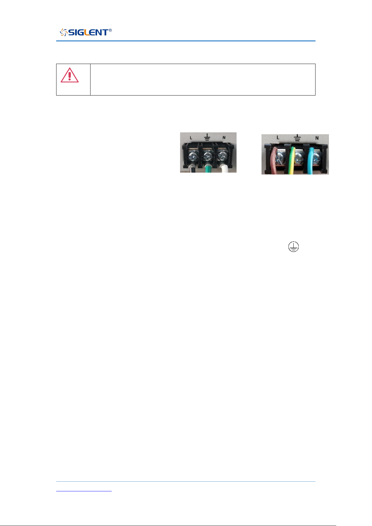
CAUTION: When using the power supply in the United Kingdom,
ensure the security of the power cord conforms to the following
instructions
Wire colors must meet the following rules:
Black/Brown: Live wire
Green/Green-yellow: Earth wire
White/Blue: Neutral wire
The wire which is coloured Black(American Standard) or Brown(European
standard)should be connected to lug labeled with the letter L.
The wire which is coloured Green(American Standard) or Greenyellow(European standard) should be connected to the earth symbol .
The wire which is coloured White(American Standard) or Blue(European
standard) should be connected to lug labeled with the letter N.
Wire connections must be made by a professional. If you have questions,
please refer to the instructions or contact your local SIGLENT dealer.
Cleaning
Clean only the exterior of the instrument, using a damp, soft cloth. Do not use
chemicals or abrasive elements. Under no circumstances should you allow
moisture to penetrate the instrument. To avoid electrical shock, unplug the
power cord from the AC outlet before cleaning.
American Standard
European standard
Page 12
SPS5000X Series User Manual
WWW.SIGLENT.COM 11
Warning: Electrical Shock Hazard!
No operator serviceable parts inside. Do not remove covers.
Refer servicing to qualified personnel
Abnormal conditions
Only operate the instrument for the purposes specified by the manufacturer.
Do not operate the power supply if there are any visible signs of damage or if
it has been subjected to severe transport stresses.
If you suspect the power supply’s protection has been impaired, disconnect
the power cord, and secure the instrument against any unintended operation.
Proper use of the instrument requires reading and understanding all of the
instructions and labels.
If the equipment is used in a manner not specified by the manufacturer, the
protection provided by the equipment may be impaired.
Warning: Any use of the power supply in a manner not specified by the
manufacturer may impair the instrument’s safety protection.
Page 13

SPS5000X Series User Manual
WWW.SIGLENT.COM 12
Documentation conventions
For the symbols appearing in the subsequent text, the convention with a
represents the menu option on the front panel of the machine, the
convention with represents the menu option displayed by the
machine, and the convention with represents the selected item of the
machine menu.
Page 14

SPS5000X Series User Manual
WWW.SIGLENT.COM 13
Informations essentielles sur la sécurité
Ce manuel contient des informations et des avertissements que les
utilisateurs doivent suivre pour assurer la sécurité des opérations et maintenir
les produits en sécurité.
Exigence de Sécurité
Lisez attentivement les précautions de sécurité ci - après afin d 'éviter les
dommages corporels et de prévenir les dommages aux instruments et aux
produits associés. Pour éviter les risques potentiels, utilisez les instruments
prescrits.
Éviter l 'incendie ou les lésions corporelles.
Utilisez une ligne d 'alimentation appropriée.
Seules les lignes d'alimentation en électricité réservées à l'usage exclusif
d'instruments reconnus au niveau local peuvent être utilisées.
Posez vos instruments par terre.
L 'appareil est mis à la Terre par des conducteurs tera protecteurs de lignes
électriques.Pour éviter le contact électrique, le fil de masse doit être mis à la
terre. Avant de connecter les bornes d 'entrée ou de sortie, assurez - vous
que l' instrument est correctement mis à la terre.
Connectez correctement la ligne de signal.
Page 15

SPS5000X Series User Manual
WWW.SIGLENT.COM 14
Le potentiel de la ligne de signaux est égal à la terre, de sorte que la ligne de
signaux ne doit pas être connectée à une haute tension.Ne touche pas les
contacts ou les composants nus.
Affiche la valeur nominale de toutes les bornes.
Pour éviter les incendies ou les coupures d 'électricité, consultez toutes les
valeurs nominales et signez la description de l' instrument. Avant de
connecter l 'instrument, lisez attentivement le Manuel pour obtenir davantage
d' informations sur la valeur nominale.
Ne pas travailler en cas de panne.
Si vous soupçonnez que l 'appareil est endommagé, demandez au personnel
d' entretien qualifié de l 'examiner.
Ne pas fonctionner dans des conditions humides / humides.
Pas dans un environnement explosif.
Maintenez la surface de l 'instrument propre et sec.
L'organisme ou l'opérateur responsable doit se référer au cahier des
charges pour protéger la protection offerte par le matériel. Veuillez
utiliser l 'instrument prescrit.
Page 16
SPS5000X Series User Manual
WWW.SIGLENT.COM 15
Termes et symboles de sécurité
Lorsque les symboles ou termes suivants apparaissent sur le panneau avant
ou arrière de l'instrument ou dans ce manuel, ils indiquent un soin particulier
en termes de sécurité.
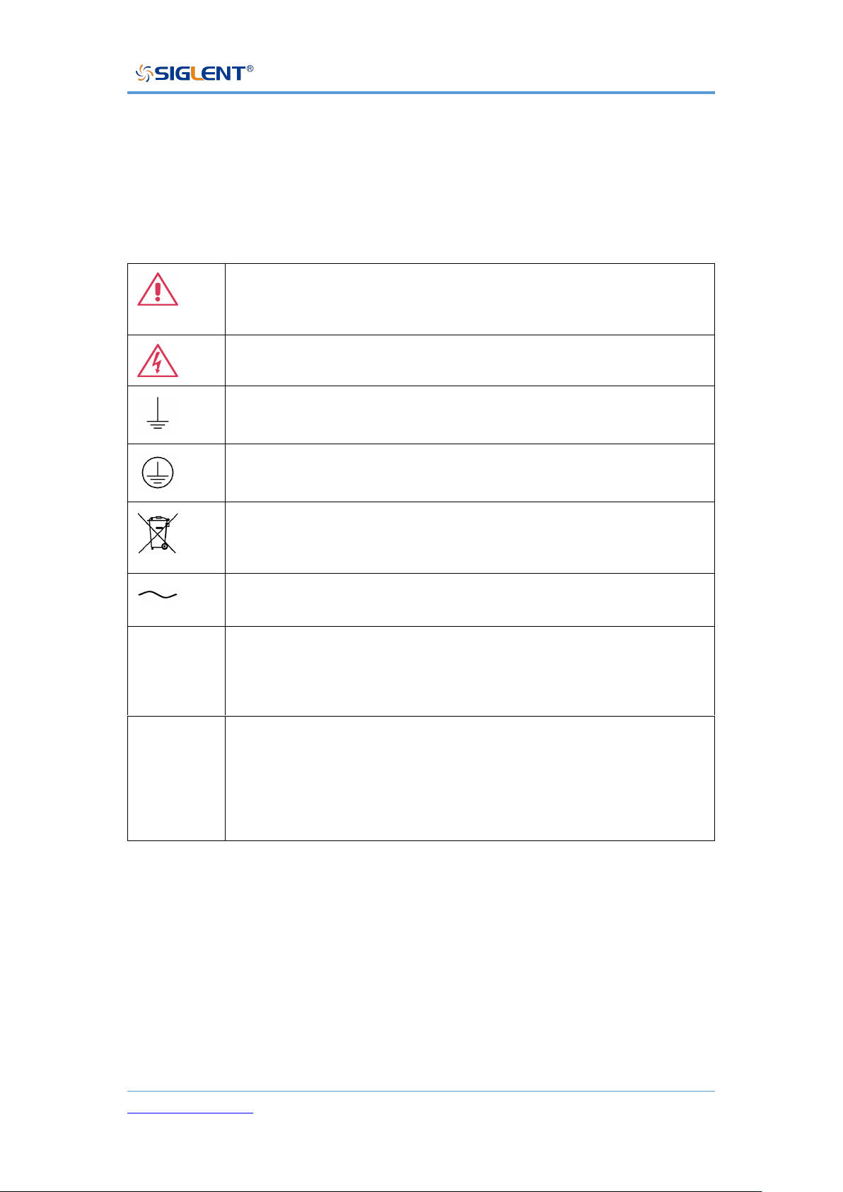
Ce symbole est utilisé lorsque la prudence est requise. Reportezvous aux informations ou documents joints afin de vous protéger
contre les blessures ou les dommages à l'instrument.
Ce symbole avertit d'un risque potentiel de choc électrique.
Ce symbole est utilisé pour désigner la connexion de terre de
mesure.
Ce symbole est utilisé pour indiquer une connexion à la terre de
sécurité.
This symbol shows that do not put electronic equipment as unsorted
municipal waste management. Please separate collection or contact
equipment suppliers.
Ce symbole est utilisé pour représenter un courant alternatif, ou
"AC".
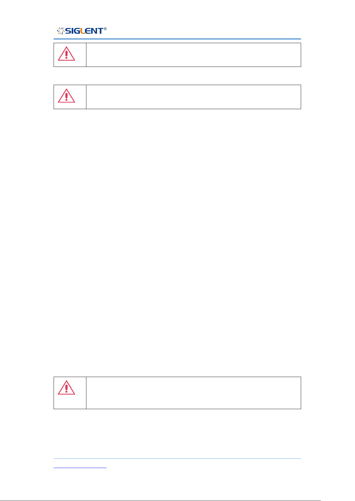
CAUTION
Le symbole " CAUTION" indique un danger potentiel. Il attire
l'attention sur une procédure, une pratique ou une condition qui peut
être dangereuse si elle n'est pas suivie. Ne continuez pas tant que
ses conditions n'ont pas été entièrement comprises et remplies.
WARNING
Le symbole " WARNING" indique un danger potentiel. Il attire
l'attention sur une procédure, une pratique ou une condition qui, si
elle n'est pas suivie, pourrait entraîner des blessures corporelles ou
la mort. Si un AVERTISSEMENT est indiqué, ne continuez pas tant
que les conditions de sécurité ne sont pas entièrement comprises et
remplies.
Environnement de travail
La conception de l'instrument a été certifiée conforme à la norme EN 61010-1,
sur la base des valeurs limites suivantes:
Environnement
Page 17

SPS5000X Series User Manual
WWW.SIGLENT.COM 16
Cet instrument est utilisé à l 'intérieur des locaux et doit être utilisé dans un
environnement propre et sec.
Température ambiante
En fonctionnement: 0 ℃ à +40 ℃
Hors fonctionnement: -20 ℃ à +60 ℃
Note: pour évaluer la température de l'environnement, il convient de tenir
compte des rayonnements solaires directs, des radiateurs thermiques et
d'autres sources de chaleur.
Humidité
Fonctionnement: 20 à 85% HR, 40 ℃, 24 heures
Hors fonctionnement: 20 à 85% HR, 65 ℃, 24 heures
Altitude
Fonctionnement: ≤ 2000m
À l'arrêt: ≤ 15 266 m
Catégorie d 'installation (surtension)
Ce produit est alimenté par une alimentation électrique conforme à l
'installation (surtension) Catégorie II.
Installation (overvoltage) Category Definitions Définition de catégorie d
'installation (surtension)
Page 18

SPS5000X Series User Manual
WWW.SIGLENT.COM 17
La catégorie II d'installation (surtension) est un niveau de signal applicable
aux terminaux de mesure d' équipement reliés au circuit source.Dans ces
bornes, des mesures préventives sont prises pour limiter la tension transitoire
à un niveau inférieur correspondant.
La catégorie II d'installation (surtension) désigne le niveau local de distribution
d 'énergie d' un équipement conçu pour accéder à un circuit alternatif
(alimentation alternative).
Degré de pollution
Alimentation électrique peut être utilisé dans un environnement Pollution
Degree II.
Note: Pollution Degree II signifie que le milieu de travail est sec et qu'il y a
une pollution non conductrice.Parfois, la condensation produit une
conductivité temporaire.
IP Rating
IP20 (as defined in IEC 60529).
Exigences de refroidissement
L 'appareil repose sur un ventilateur interne et un ventilateur de
ventilation.Attention.Des mesures doivent être prises pour éviter de limiter le
flux d 'air autour de l' ouverture arrière de l 'alimentation (orifice de
ventilateur).Gardez une bonne ventilation lors de l 'utilisation et vérifiez
régulièrement les ventilateurs et les ventilateurs.
Page 19
SPS5000X Series User Manual
WWW.SIGLENT.COM 18
ATTENTION: Ne bloquez pas les orifices de ventilation de l
'arrière de l' alimentation.
ATTENTION: Ne laisse aucun objet étranger entrer dans l
'alimentation électrique, par exemple par le trou de ventilation.
Connexions d'alimentation et de terre
L'instrument fonctionne avec une alimentation CA monophasée de 100 à 240
Vrms (+/- 10%) à 47 à 63Hz (+/- 5%).
Les bornes de mise à la terre de protection des prises d 'alimentation en
courant alternatif sont mises à la terre afin d' éviter les chocs électriques.
Il n 'est pas nécessaire de sélectionner la tension manuellement, car l'
instrument s' adapte automatiquement à la tension du circuit.
L 'instrument s' adapte automatiquement aux entrées de lignes de
communication dans les limites suivantes:
Plage de tension: 90 à 264 vrms, plage de fréquence: 47 à 63 Hz.
ATTENTION: Lorsque le Royaume - Uni utilise l'énergie
électrique, la sécurité des lignes électriques est assurée
conformément à la description ci - après.
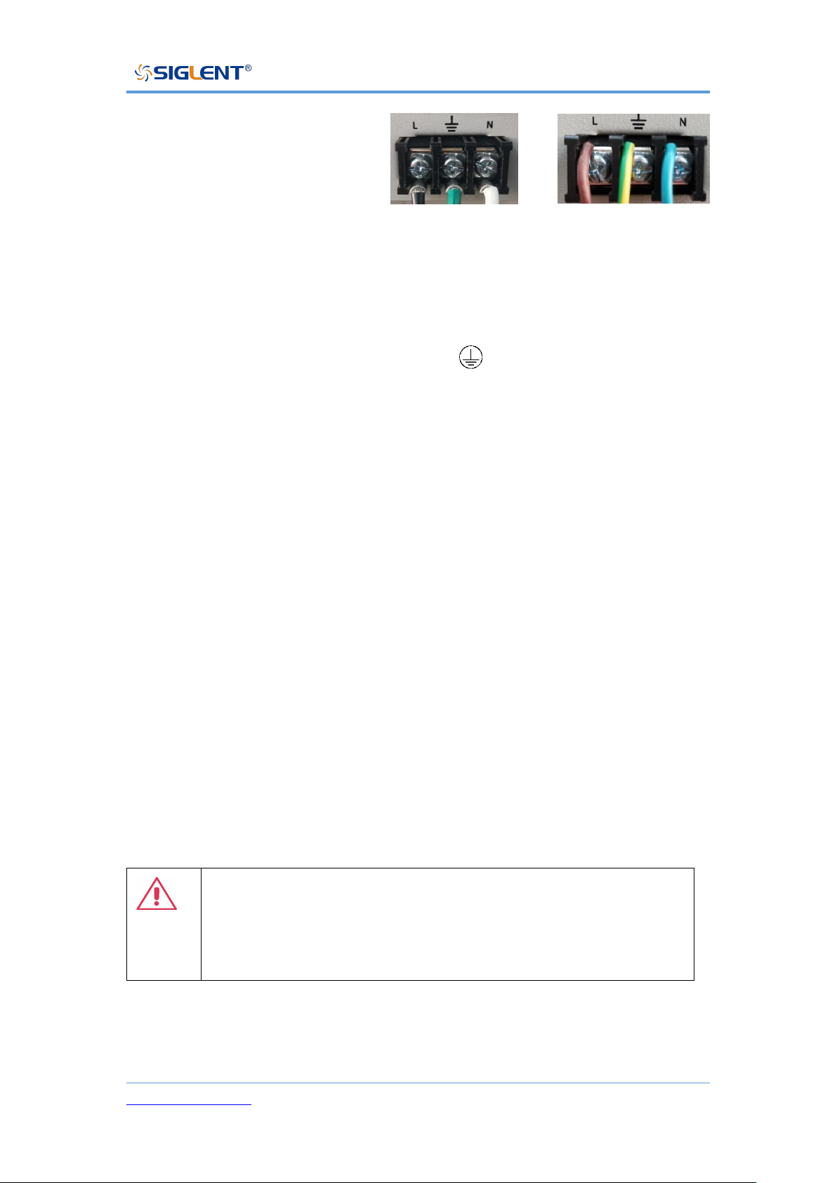
La couleur du fil doit être conforme aux règles suivantes:
Page 20
SPS5000X Series User Manual
WWW.SIGLENT.COM 19
Noir / brun: conducteur vivant
Vert / vert - jaune: sol
Blanc / bleu: neutre
Les fils noirs (norme américaine) ou bruns (norme européenne) doivent être
raccordés aux languettes marquées de la lettre L.
Le conducteur vert (norme américaine) ou vert - jaune (norme européenne)
doit être relié au symbole de mise à la terre .
Les fils blancs (norme américaine) ou bleus (norme européenne) doivent être
raccordés aux languettes marquées de la lettre N.
Le câblage doit être effectué par un professionnel.Si vous avez des questions,
consultez les instructions ou contactez votre revendeur siglent local.
Nettoyage
Nettoyez uniquement l'extérieur de l'instrument à l'aide d'un chiffon doux et
humide. N'utilisez pas de produits chimiques ou d'éléments abrasifs. Ne
laissez en aucun cas l'humidité pénétrer dans l'instrument. Pour éviter les
chocs électriques, débranchez le cordon d'alimentation de la prise secteur
avant de le nettoyer.
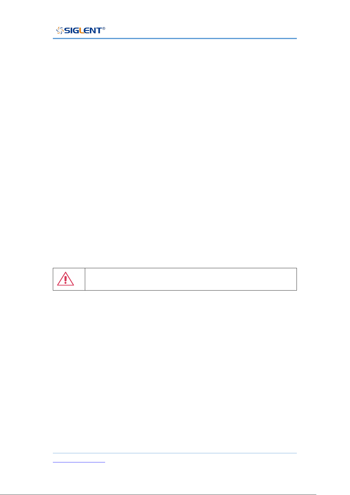
Avertissement: risque de choc électrique!
Aucune pièce réparable par l'opérateur à l'intérieur. Ne retirez pas les
capots.
Confiez l'entretien à un personnel qualifié
American Standard
European standard
Page 21
SPS5000X Series User Manual
WWW.SIGLENT.COM 20
Conditions anormales
Utilisez l'instrument uniquement aux fins spécifiées par le fabricant.
N'utilisez pas la lunette s'il y a des signes visibles de dommages ou si elle a été
soumise à de fortes contraintes de transport.
Si vous doutez que la protection de l 'alimentation électrique soit compromise,
désactivez la ligne d' alimentation et fixez l 'appareil afin d' éviter toute
manipulation accidentelle.
Une bonne utilisation de l'instrument nécessite la lecture et la compréhension
de toutes les instructions et étiquettes.
La protection offerte par le matériel peut être compromise si celui - ci est utilisé
de manière non spécifiée par le fabricant.
Avertissement: L'utilisation de l'énergie de manière non prescrite
par le fabricant peut compromettre la sécurité des instruments.
Page 22

SPS5000X Series User Manual
WWW.SIGLENT.COM 21
Delivery of The Power Supply
General Inspection
Note: Before your first use of the equipment, please check the condition using
the steps below.
• Inspection of transport packaging
If it is found that the packing box or foam plastic pad is seriously damaged,
please save it for subsequent inspection. The carrier and shipper must be
contacted for any damage caused during transport. The SIGLENT company is
not responsible for any damage caused during shipment.
• Check the equipment
If there is mechanical damage, missing parts, or the instrument fails to pass the
electrical and mechanical tests, please contact the nearest SIGLENT office or
distributor as soon as possible.
• Check the accessories
Detailed information about included accessories is included at the end of this
document. Please refer to this description to check whether the attachment is
delivered completely. If there is any omission or damage, please contact the
local SIGLENT customer service center or national distributors. If you fail to
contact us in time in case of omission or damage, we will not be responsible for
replacement.
Page 23

SPS5000X Series User Manual
WWW.SIGLENT.COM 22
About Warranty
The power supply has a 3-year warranty for normal use and operation from the
date of delivery. SIGLENT may repair or choose to replace any product returned
to the authorized service center during the warranty period. But to do so, we
must first examine the product to determine that the defect is caused by the
process or material, not by abuse, negligence, accident, abnormal conditions,
or operation.
SIGLENT is not responsible for any situation caused by any defect, damage or
malfunction caused by the following:
a) Maintenance or installation by personnel other than those authorized by
SIGLENT
b) Connection of incompatible equipment and improper connection
c) Any damage or failure caused by the use of products not supplied by
SIGLENT suppliers.
Also, SIGLENT will not be responsible for the maintenance of the modified
or integrated power supply product if the product has been modified or
integrated and these changes or integration increase the time or difficulty of
power maintenance tasks.
All spare parts and replacement parts and maintenance are guaranteed for
90 days.
The power supply software has been fully tested and is considered to be
functioning properly. However, the software is provided without any type of
warranty covering detailed performance. Products not manufactured by
SIGLENT are guaranteed by the OEM only.
Page 24

SPS5000X Series User Manual
WWW.SIGLENT.COM 23
Maintenance Agreement
We provide various services based on individual maintenance agreements. We
offer extended warranties which can extend the warranty period beyond the
standard period. We provide installation, training, enhancement and on-site
maintenance and other services through a dedicated supplemental support
agreement. For details, please contact your nearest SIGLENT customer service
center or national distributors.
Page 25
SPS5000X Series User Manual
WWW.SIGLENT.COM 24
Introduction of SPS5000X Series
The SIGLENT SPS5000X series is a programmable DC switching power supply
with single/multiple outputs and constant power features. The series includes
15 models, with 40 V, 50V, 80 V, 160 V rated output voltage values and 180W,
360 W, 720 W, 1080 W maximum output power levels. Users can connect 2
sets of power supplies in series or up-to 3 sets in parallel. This series of
products can meet the user's combination selection of 0 ~ 320 V, 0 ~ 270 A,
and the maximum combined power can reach up to 3240 W, meeting different
application requirements.
SPS5000X series programmable DC switching power supply is equipped with
a 2.4-inch high brightness OLED display, friendly human-computer interaction
interface, and excellent performance indicators. The minimum resolution is
1mV / 1mA. The output voltage and current rise time is adjustable. It has two
output modes: Constant voltage and constant current. It also supports list
sequence programming mode. It also has over-voltage, over-current, power
limit and over-temperature protection, high-precision, low-noise, and highreliability.
Standard LAN / USB communication interface, analog control interface, the
product can be remotely controlled through web pages. It can be widely used
in a variety of demanding testing places, such as general laboratory testing,
LED lighting industry, automotive electronics, and other fields.
Page 26
SPS5000X Series User Manual
WWW.SIGLENT.COM 25
Performance and Features
Rated voltage: 40 V, 50V, 80 V, 160 V
Rated output power: 180W, 360 W, 720 W, 1080 W
Constant power output, a wide range of voltage and current outputs, high
efficiency switching power supply
CV, CC priority mode selection, better protection for the circuit/DUT
Fast recovery time, < 1 ms
Fast output response time, < 1 ms
Voltage and current rise/fall rate adjustable
Set and read back resolution 1 mV, 1 mA
Built-in bleeder current control, the power in the output capacitor can be
discharged below the circuit/DUT safe voltage after shutdown
Support remote voltage compensation Sense function
Support local list function editing, USB import list sequence file
External analog voltage and resistance control, voltage and current
monitoring output
Overvoltage, over current, power limit, over-temperature protection, safe
and reliable
2.4-inch OLED high-brightness display with a wide viewing angle of 170
degrees
Equipped with USB, LAN standard communication interface, optional USB-
GPIB module
With 1/2, 1/3, 1/6 rack size, flexible assembly
Embedded web server provides remote computer by web browser without
the need to install additional software on the host computer
Page 27
SPS5000X Series User Manual
WWW.SIGLENT.COM 26
Model Introduction
The SPS5000X series includes 16 models, with four voltage output types of
40V / 50V / 80V / 160V, with up to three output channels:
Model
Type
Channels
Voltage (V)
Current (A)
Power (W)
SPS5041X
Ⅰ
1
0~40
0~30
360
SPS5042X
Ⅱ
1
0~40
0~60
720
SPS5043X
Ⅲ
1
0~40
0~90
1080
SPS5044X
Ⅳ
2
0~40/CH
0~30/CH
360/CH
SPS5045X
Ⅴ
3
0~40/CH
0~30/CH
360/CH
SPS5051X
Ⅰ
1
0~50
0~10
180
SPS5081X
Ⅰ
1
0~80
0~15
360
SPS5082X
Ⅱ
1
0~80
0~30
720
SPS5083X
Ⅲ
1
0~80
0~45
1080
SPS5084X
Ⅳ
2
0~80/CH
0~15/CH
360/CH
SPS5085X
Ⅴ
3
0~80/CH
0~15/CH
360/CH
SPS5161X
Ⅰ
1
0~160
0~7.5
360
SPS5162X
Ⅱ
1
0~160
0~15
720
SPS5163X
Ⅲ
1
0~160
0~22.5
1080
SPS5164X
Ⅳ
2
0~160/CH
0~7.5/CH
360/CH
SPS5165X
Ⅴ
3
0~160/CH
0~7.5/CH
360/CH
Page 28
SPS5000X Series User Manual
WWW.SIGLENT.COM 27
SPS5000X Series Overview
Appearance
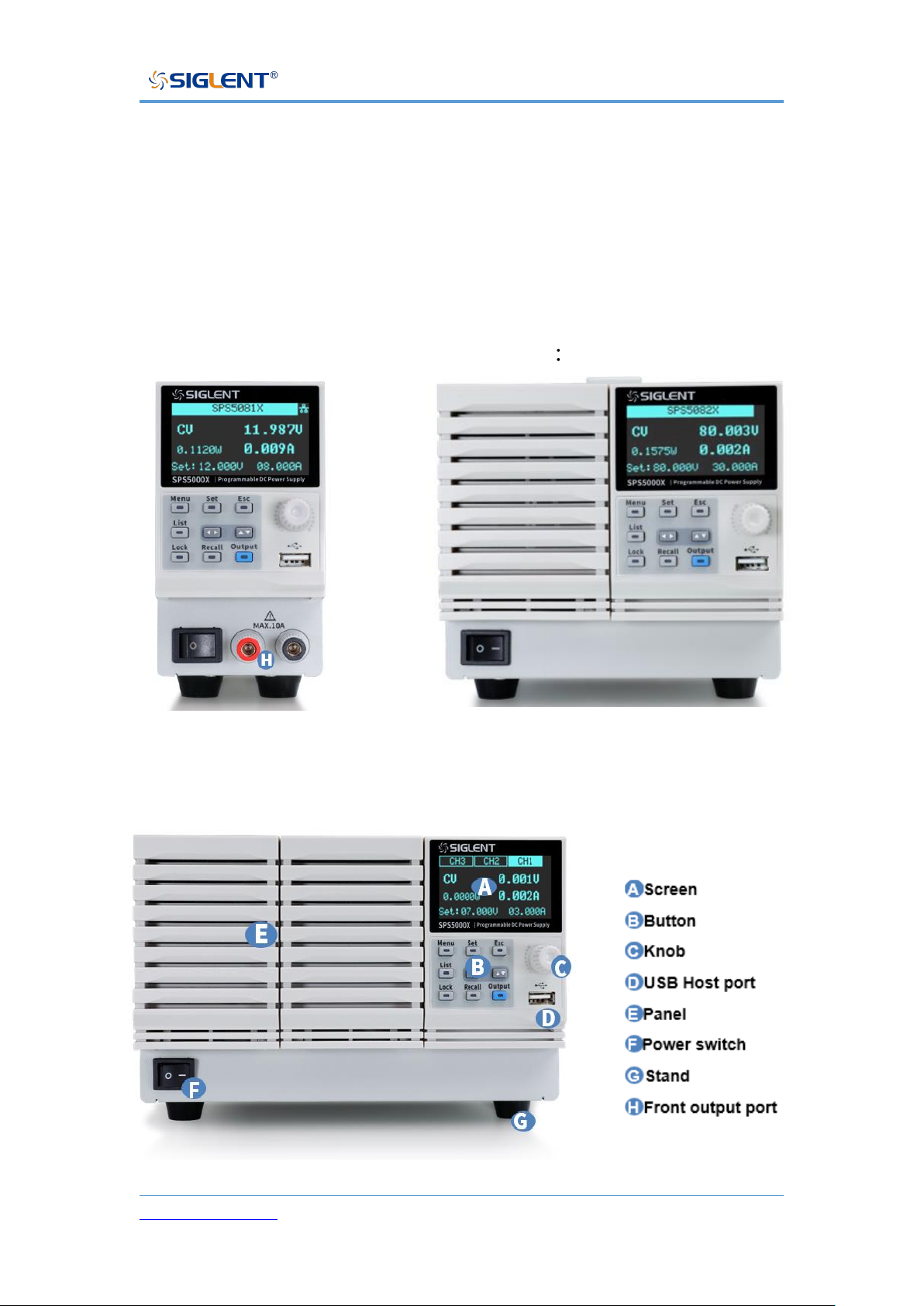
The SPS5000X series has three different appearance panels, distinguished by
TypeⅠ, TypeⅡ/TypeⅣ, TypeⅢ/TypeⅤ:
TypeⅠ TypeⅡ/TypeⅣ
TypeⅢ/TypeⅤ
Page 29
SPS5000X Series User Manual
WWW.SIGLENT.COM 28
A Screen
All SPS supplies include a 2.4-inch OLED display for displaying system output
status, system parameter settings, menu options, and promotion information.
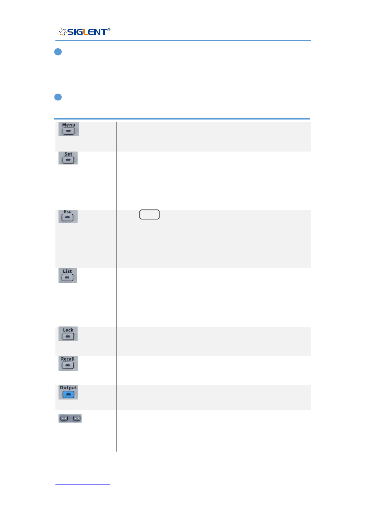
B Button
Used to view system information and configure power
parameters.
In the main interface, press this key to select and set the
output voltage value or output current value.
Press this key in the function area to enter the next menu,
which is equivalent to the confirm key.
Press Menu to enter the menu list, press this key to return
to the previous menu.
When the power supply enters the protection state, long
press the key to release the protection mode
Press this key to enter the List mode, you can set each
group of output current, output voltage and running time,
etc.
Press this key again to exit the List interface
Press this key to turn on the keyboard lock function, long
press to release the key lock.
Used to recall or store the state. If you select List, press
this key to store or recall the List state.
Power output button used to turn the output on or off.
The direction buttons are used to switch the digits of the
value where the cursor is selected, and to move the cursor
position or switch options.
Page 30
SPS5000X Series User Manual
WWW.SIGLENT.COM 29
C Direction knob
When setting parameters, turn the knob to increase or decrease the value at
the cursor.
When setting objects (voltage or current, operation mode, internal resistance
configuration, etc.), rotate the knob to quickly move the cursor position or switch
options, press the knob to set the current parameters, rotate the knob to
increase or decrease the value at the cursor, and press again to make the
current setting effective.
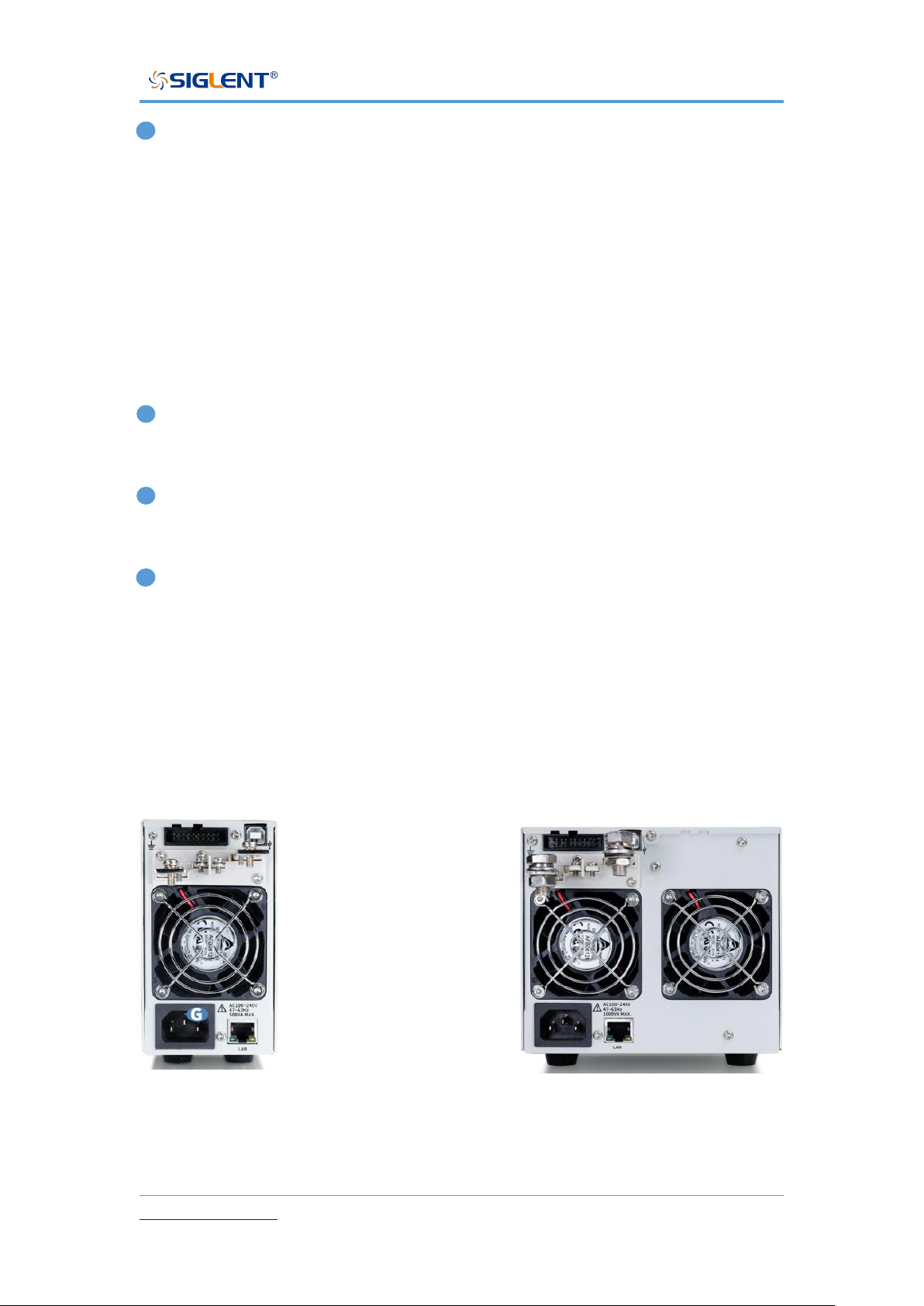
D USB Host port
Used to insert peripheral USB devices for file transfer and system upgrades.
F Power Switch
Used to turn the power on or off.
H Front output port (positive (+), negative (-))
The current output front port can output a maximum current of 10 A.
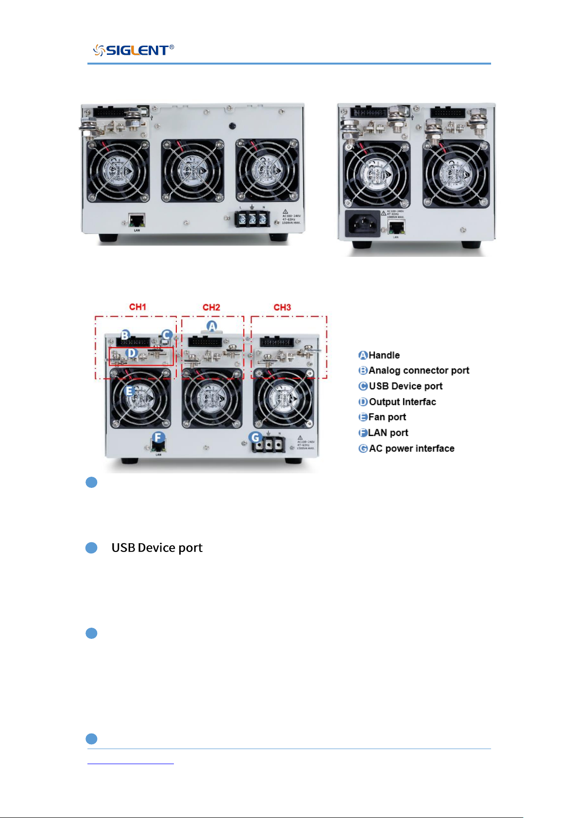
Rear Panel
Type Ⅰ Type Ⅱ
Page 31
SPS5000X Series User Manual
WWW.SIGLENT.COM 30
Type Ⅲ Type Ⅳ
Type Ⅴ
B Analog connector port
Output for the monitor signals of voltage and current output. Also used for
analog control of the current and voltage outputs.
C
This interface can be connected to a PC for remote communication via USB
using the USBTMC protocol. Provides remote computer control of the supply
by sending commands through computer software.
D Output Interface
One set of positive (+) and negative (-) output terminals, type IV has two output
orts, and type V has three output ports. On units with multiple output channels,
the channels are arranged as follows (when facing the rear panel): From right
to left, the one near the display is CH1, then CH2, CH3.
E Fan port
Page 32

SPS5000X Series User Manual
WWW.SIGLENT.COM 31
The temperature-controlled fan effectively dissipates the heat of the power
supply line over all operating conditions.
F LAN port
Supplies a connection between the power supply and a LAN. SPS5000X
conforms to the VXI-11 instrument standard and supports Socket-based and
remote commands, and remote control. It can quickly build a test system with
other standard equipment and easily achieve system integration.
AC power interface
The AC power supply supports 100 ~ 240 V, 47 Hz ~ 63 Hz. Please use the
provided power cord to connect to MAINS. For different types of power interface
connections, please refer to [7.1].
Page 33
SPS5000X Series User Manual
WWW.SIGLENT.COM 32
Theory of Operation
This chapter introduces the function and principles of operating the SPS5000X
series power supply.
Operating Area Description
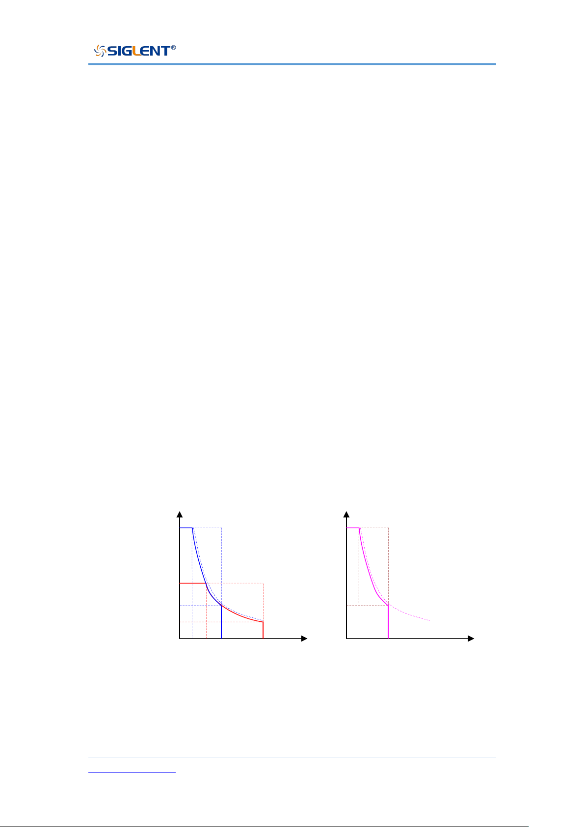
SPS5000X are DC switching power supplies with high voltage and current
output. All models have continuous voltage (CV) and continuous current (CC)
output control modes with working ranges limited only by the output power. The
working area is determined by the rated output power and the rated voltage and
current.
When the total output power of the power supply (voltage x current output) is
less than the rated power output, the SPS operates as a typical constant voltage
and constant current power supply.
When the total output power (voltage x current output) is greater than the rated
power output, the effective output is limited to 105% of the rated power. At this
time, the output voltage and current are only related to the load value as shown
below:
I(A)
V(V)
10
20
30
40
50
60
70
80
5 10 15 20 25 30 35 40
4.5A
24V
9A
12V
I(A)
V(V)
20
40
60
80
100
120
140
160
2.5 7.5 15
2.25A
48V
Page 34
SPS5000X Series User Manual
WWW.SIGLENT.COM 33
CC and CV Mode
When the power supply is operating in CV mode, the load receives a constant
voltage, and the current output changes with the load. When the load resistance
is too low to maintain the constant voltage, the power supply switches to CC
mode, and the current limit remains constant.
When the power supply is operating in constant current mode (CC), the load
receives constant current. Even if the output voltage is changed, the current
remains the same. If the load resistance increases to the current limit (Iset) or
greater, the power supply switches to CV mode. This switching point is called
the crossover point, and the local state is displayed as ALT.
The power supply operates in CV or CC mode, which is determined by the set
voltage (Vset), set current (Iset), load resistance (RL) and critical resistance (Rc,
Rc=Vset/Iset). When RL>Rc, the power supply runs in CV mode. At this time,
Vout=Vset, Iout<Iset. If RL decreases, when Iout=Iset, the power supply
switches to CC mode.
On the contrary, when the load resistance is less than the critical resistance,
the power supply operates in CC mode. In CC mode, the output current is equal
to Iset and the output voltage is less than Vset.
CV priority mode CC priority mode
Page 35
SPS5000X Series User Manual
WWW.SIGLENT.COM 34
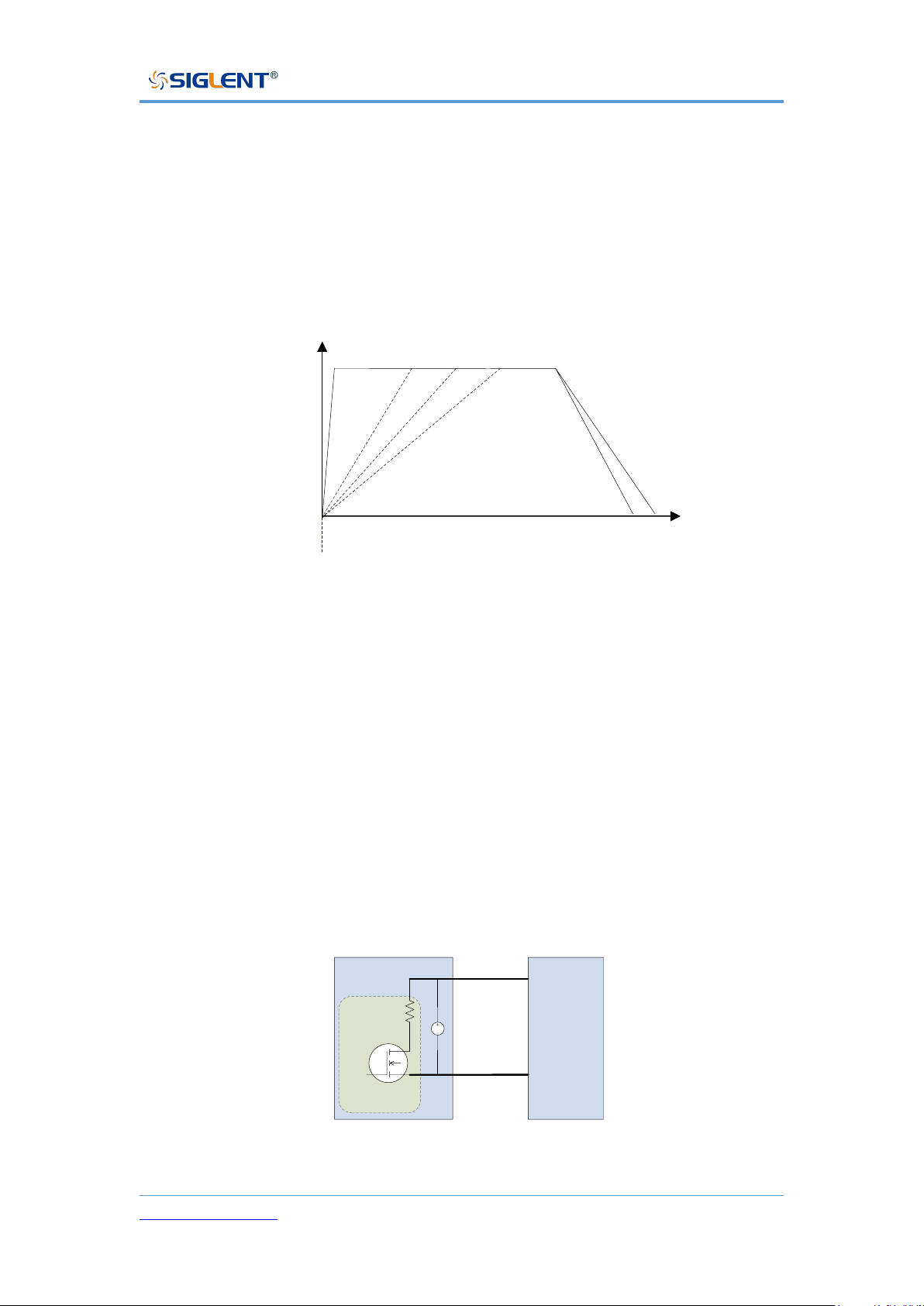
Slew Rate
The slope of CV and CC mode can be selected to limit the voltage and current
consumption. The slope setting is divided into high-speed priority and slope
priority. The high-speed priority mode does not allow setting the slope in CV or
CC mode, while the rising and falling slopes can be set independently in the
slope priority mode.
V(V)
T
0
ON
slew rate
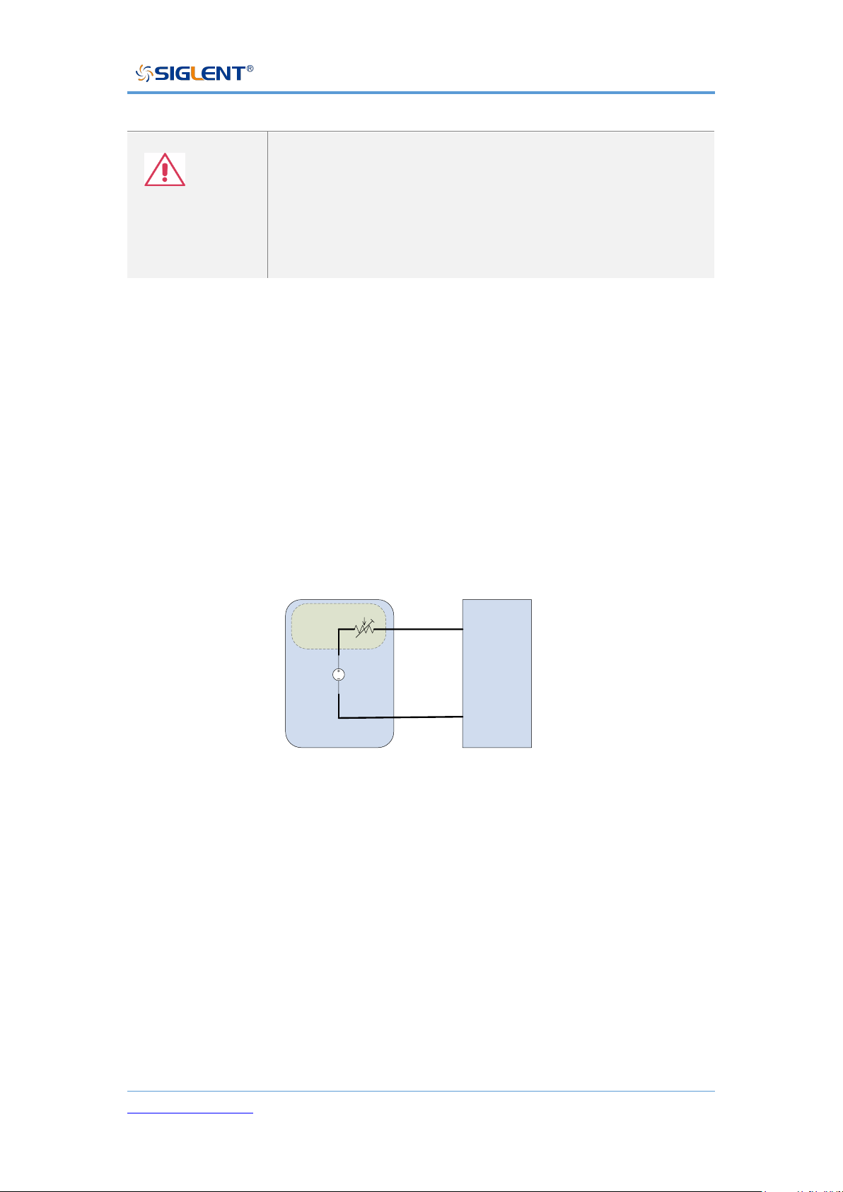
Bleeder Control
The SPS power supplies feature a bleeder resistor. When the power is turned
off and the load is disconnected, the bleeder resistor will consume the power in
the output capacitor. Without a bleeder resistor, the output capacitor would
continue to be charged, causing potential danger.
The bleeder resistance can also play a role in smoothing the voltage regulation
rate.
Load
DC
SPS5000X
+
-
discharge circuit
Bleeder circuit
Page 36
SPS5000X Series User Manual
WWW.SIGLENT.COM 35
Note
The bleeder resistor is turned on by default. In battery
charging applications, make sure to turn off the bleeder
resistor when the instrument is turned off because the
bleeder resistor will discharge the connected battery.
Internal Resistance
The internal resistance can be customized in the configuration menu of the
power supply. After setting, it can be regarded as a resistor in series with the
positive output terminal. At this time, the power supply behaves like power
source with internal resistance, such as a lead-acid battery.
Load
DC
SPS5000X
+
-
Internal
resistance
Page 37
SPS5000X Series User Manual
WWW.SIGLENT.COM 36
SPS Model
Internal Resistance Range
SPS5041X
0 ~ 1.5 Ω
SPS5042X
0 ~ 0.75 Ω
SPS5043X
0 ~ 0.5 Ω
SPS5044X
0 ~ 1.5 Ω
SPS5045X
0 ~ 1.5 Ω
SPS5051X
0 ~ 6 Ω
SPS5081X
0 ~ 6 Ω
SPS5082X
0 ~ 3 Ω
SPS5083X
0 ~ 2 Ω
SPS5084X
0 ~ 6 Ω
SPS5085X
0 ~ 6 Ω
SPS5161X
0 ~ 24 Ω
SPS5162X
0 ~ 12 Ω
SPS5163X
0 ~ 8 Ω
SPS5164X
0 ~ 24 Ω
SPS5165X
0 ~ 24 Ω
Alarms
The power supply has a protection function. When the protection alarm is set,
the protection mechanism will be triggered and respond accordingly when the
set conditions are reached.
OVP
The overvoltage protection (OVP) function prevents
the load from being damaged by high voltage and
triggers the output to be disconnected.
OCP
The overcurrent protection (OCP) function prevents
Page 38
SPS5000X Series User Manual
WWW.SIGLENT.COM 37
the load from being damaged by high current and
triggers the output to be disconnected.
OTP
Overtemperature protection function can prevent the
instrument from overheating damage and
automatically disconnect the output.
Alarm output
The alarm output is a separate open collector
photocoupler output. When the protection settings
(OCP, OVP, OTP) are exceeded, the power supply
will automatically shut down and an alarm will be
output via the analog control interface.
Considerations
The following conditions should be considered when using SPS power supplies:
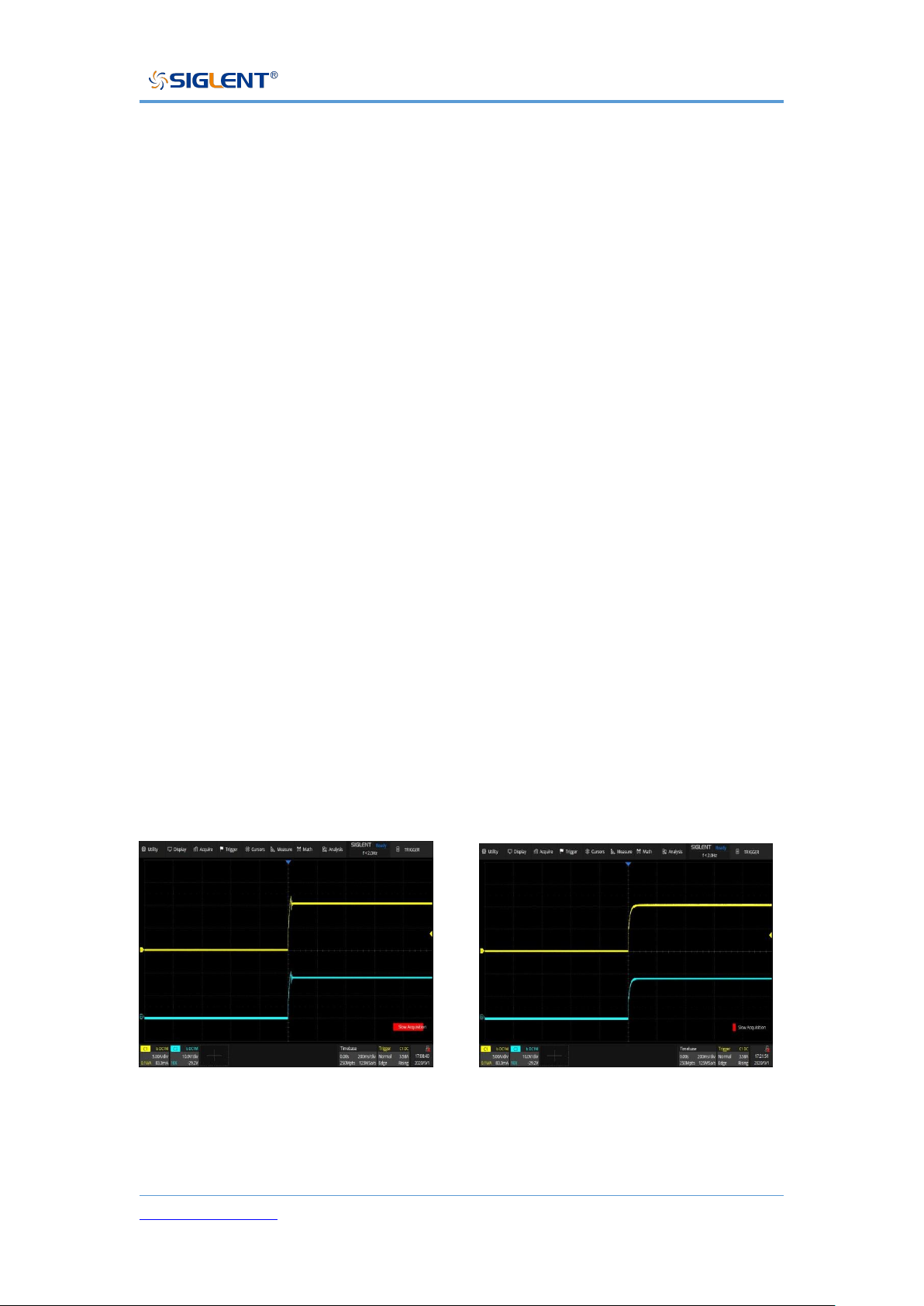
Inrush current
The power supply generates an inrush current when it is turned on. Ensure that
the power supply is sufficient at the moment of starting, especially when multiple
power supplies are turned on at the same time.
Note
In a short time, the switching power supply will generate
inrush current, reducing the service life of the power
switch of the input fuse box.
Page 39
SPS5000X Series User Manual
WWW.SIGLENT.COM 38
Pulsed or Peaked loads
The load is subject to current peaks or pulses, and the maximum current may
exceed the average current value. The power supplies only display the average
current value. For pulsed current loads, the actual current may be greater than
the displayed value. At this time, the current limit must be increased or the large
power supply must be turned off.
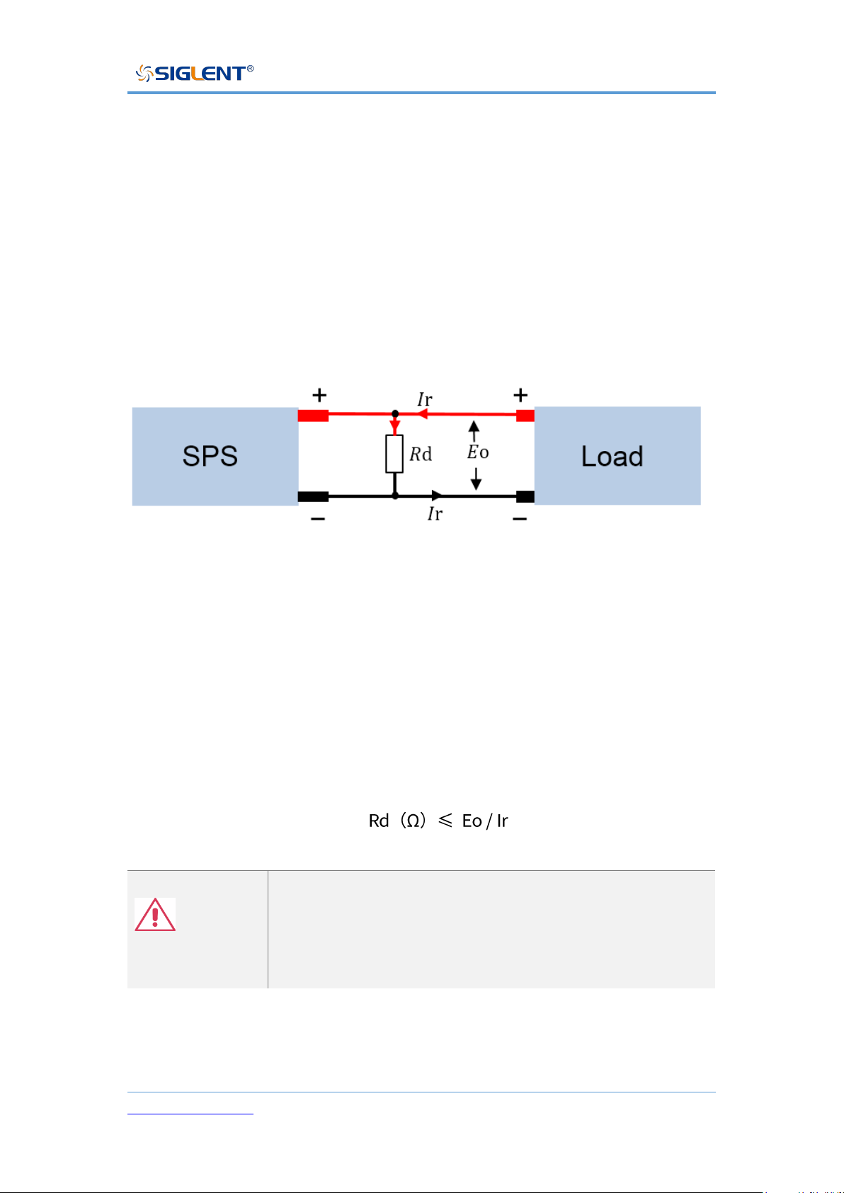
Reverse current regenerative load
When the power supplies are connected to regenerative loads (such as
transformers and inverters), the reverse current will be fed back to the power
supply and cannot be absorbed by the power supply. For such a load that can
generate reverse current, a resistor must be connected in parallel with the
power supply to avoid the inflow of reverse current. This method is only
applicable when the bleeder resistor is closed.
To calculate the resistance value (Rd) of the virtual resistor, first determine the
maximum reverse current Ir and determine the output voltage Eo.
Note
As the current decreases, the resistance of the output is
partially absorbed.
Ensure that the resistor used can withstand the power
capacity of the power supply or load.
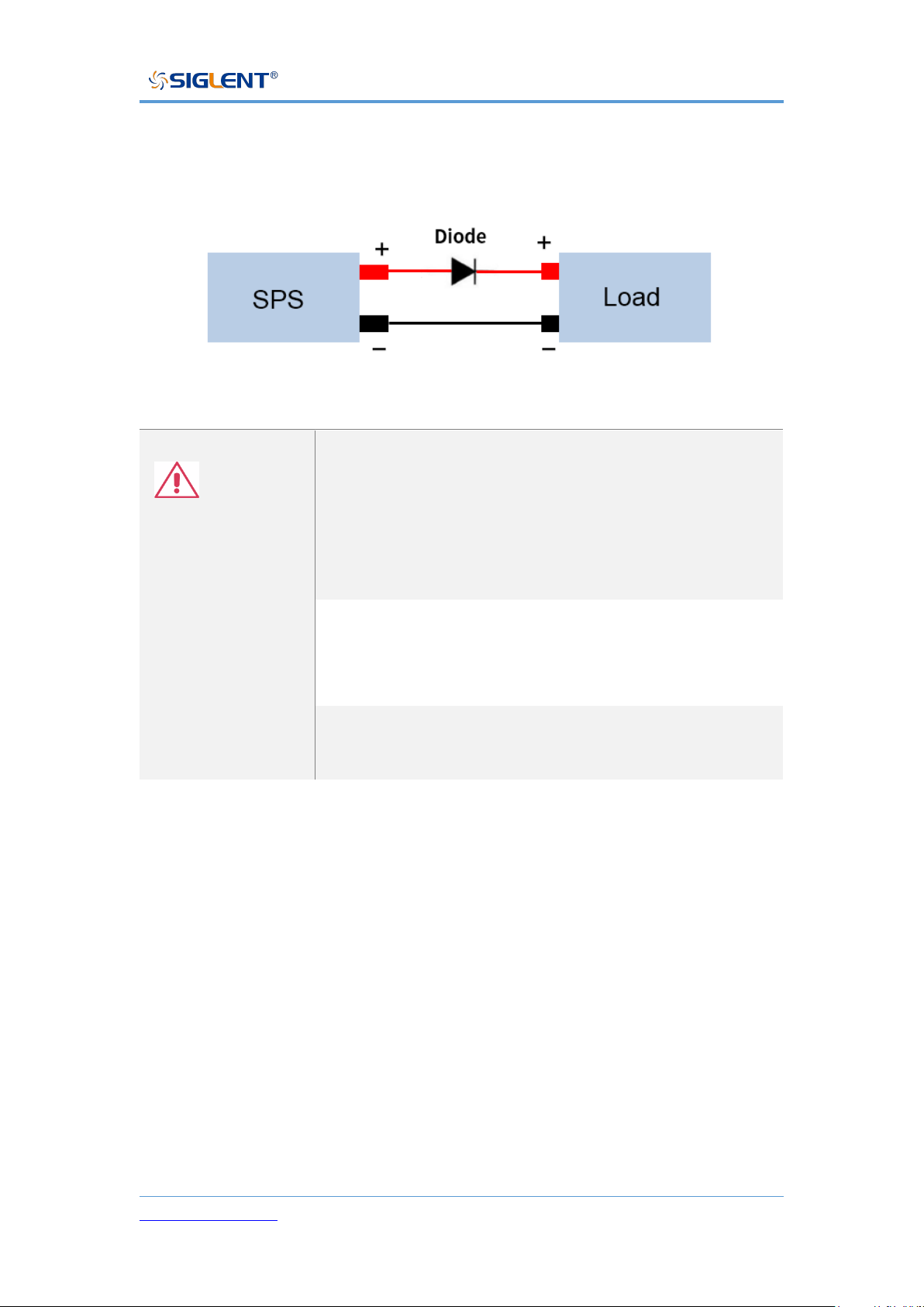
Reverse current connection method
When the power supplies are connected to a load such as a battery, reverse
Page 40
SPS5000X Series User Manual
WWW.SIGLENT.COM 39
current may flow into the power supply. To prevent damage to the power supply,
connect a reverse protection diode in series between the power supply and the
load.
Note
Ensure that the reverse voltage of the protection diode
can withstand 2 times the rated output voltage of the
power supply and that it can withstand 3 ~ 10 times of
the rated output current of the power supply in forward
(conduction) current.
Ensure that the diode can withstand the subsequent
heat generated by the maximum power that the supply
can deliver.
When a diode is used to limit the reverse voltage, the
remote measurement function should be turned off
Grounding
The output terminals of the power supplies are independent of the protective
ground terminal. When in protective grounding or floating low, the insulation
capacity of the load, load line, and other connected equipment must be
considered.
Floating
When the output terminal is floating, the load and all load wires must be
insulated, and the insulation capacity should be greater than the insulation
Page 41
SPS5000X Series User Manual
WWW.SIGLENT.COM 40
voltage of the power supply.
Grounded output terminal
If the positive/negative terminal is connected to the protective ground terminal,
the insulation capacity required by the load and the load line will be greatly
reduced. The insulation capacity only needs to be greater than the maximum
output voltage of the power supply.
Note
If using external voltage control, please do not
ground the external voltage terminal, otherwise, it will
cause a short circuit.
Page 42
SPS5000X Series User Manual
WWW.SIGLENT.COM 41
Switch On / Off and Output Port
Connect the Power Cord
Type I / type II / type IV supplies have a power interface with a 10 A input port:
use the power cord provided to connect to the socket on the rear panel.
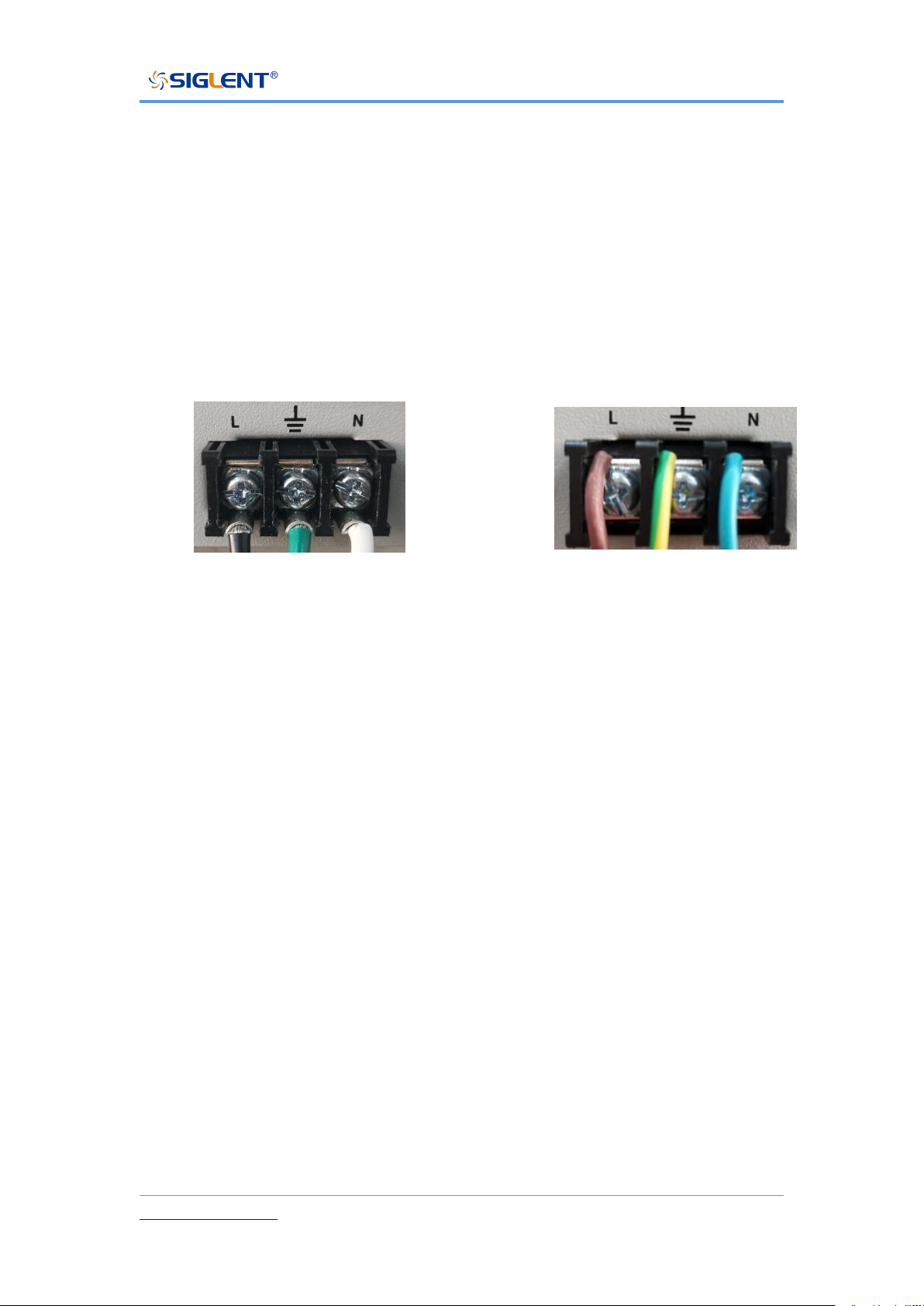
Type III / type V supplies have the following power cord connection method:
1) Turn off the power switch;
2) Connect the AC input terminal to the AC power cord;
Black/Brown: The live/hot wire, connected to port L.
Green/Green-yellow: The ground wire is connected to the terminal with a
grounding mark.
White/Blue: The neutral/zero line, connected to port N.
3) Install the protective cover.
Power On
The SPS5000X is powered on manually. After the power is connected to the AC
power source through the power cord, manually press the power button to start
the instrument and enter the boot interface.
American Standard
European standard
Page 43
SPS5000X Series User Manual
WWW.SIGLENT.COM 42
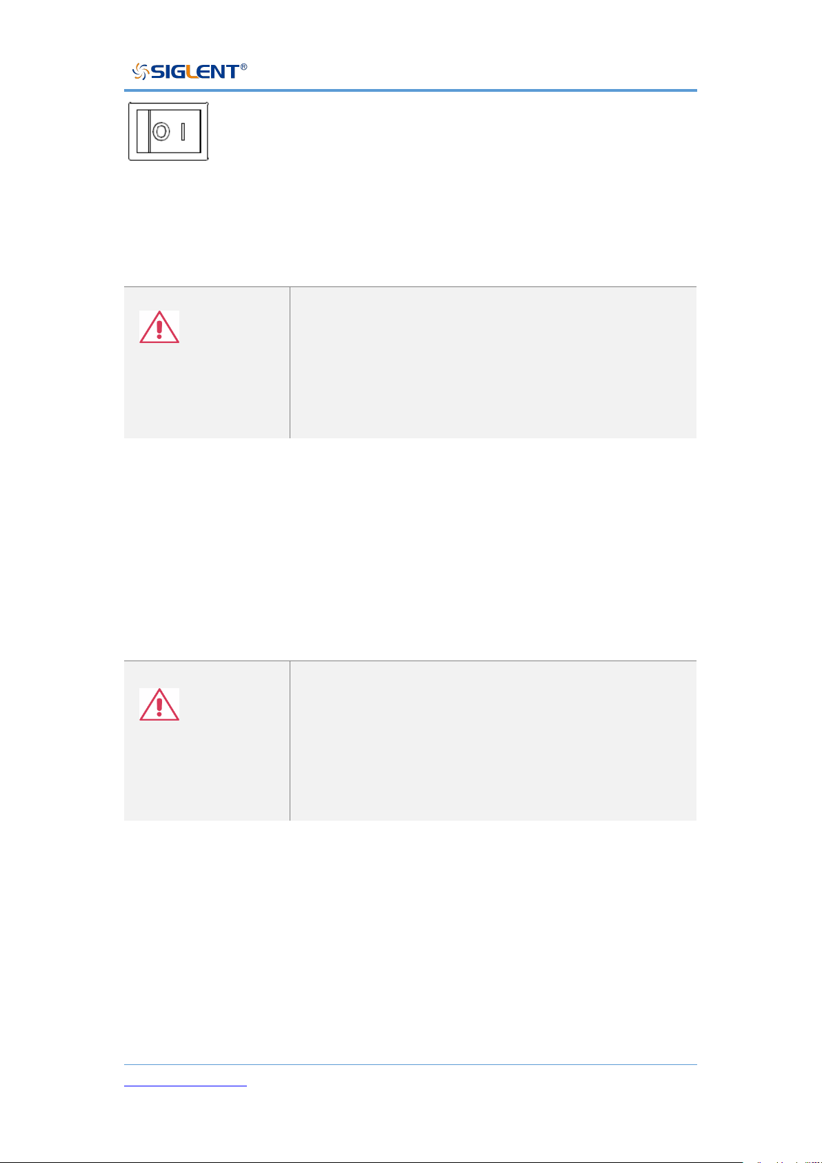
When the switch is in 1 state, it means that the switch is on. At this
time, if there is sufficient AC power from MAINS, the power supply is in the on
state.
Note
The power supplies generate an inrush current when
turned on. Please make sure that the power supply is
sufficient at the moment of turning on, especially when
multiple power supplies are turned on at the same
time.
Power Off
Press the switch button on the panel to set the 0 position to turn off the power.
Warning
It takes about 8 seconds for the power to be fully
turned on and off.
Do not turn the power on and off quickly. Please wait
at least 10 seconds before changing the output switch
state.
Attention
When the power supply is on, quickly chaging the output state may damage the
power supply. Do not continuously change the output state of the supply.
Page 44
SPS5000X Series User Manual
WWW.SIGLENT.COM 43
Output Port
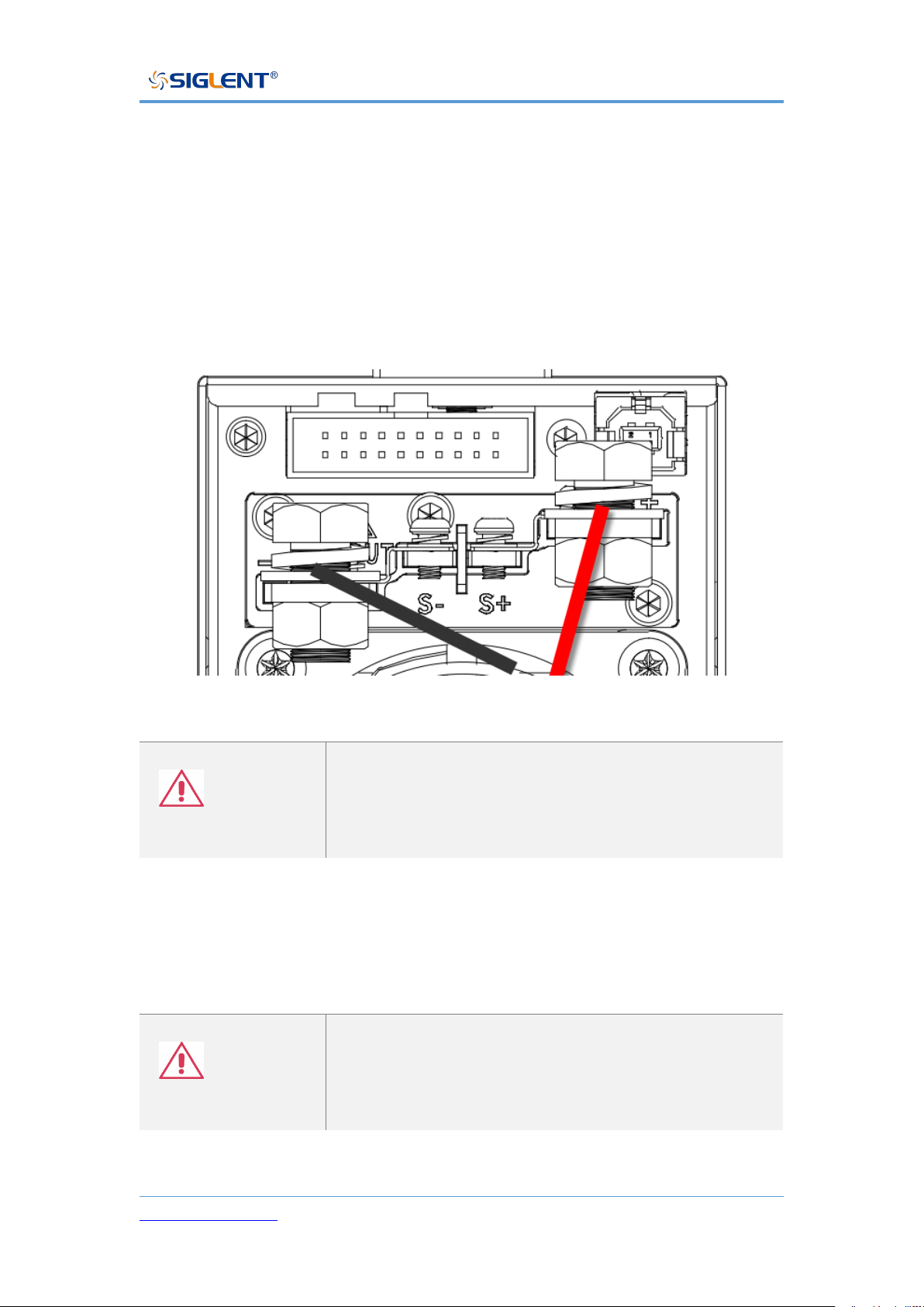
Before connecting the output terminal to the load, consider the cable
specifications and the maximum voltage of the load. Connect the output
terminal and load line with M4 screw or M8 bolt (> 30A). If remote voltage
measurement is used, remove the connection terminals on S +, S - and output,
and connect the S +, S - detection lines to the load. For the most accurate power
delivery, connect the S+ and S- as close to the load as possible
Warning
The power switch must be turned off before installing
wiring at the power output terminal.
Otherwise, there may be a risk of electric shock.
The single-module model also has a front output port that can output a
maximum current of 10 A.
Warning
The front and rear outputs cannot be used at the same
time. When the front output is connected with the load,
the rear port should not be connected with the load.
Page 45
SPS5000X Series User Manual
WWW.SIGLENT.COM 44
User Interface
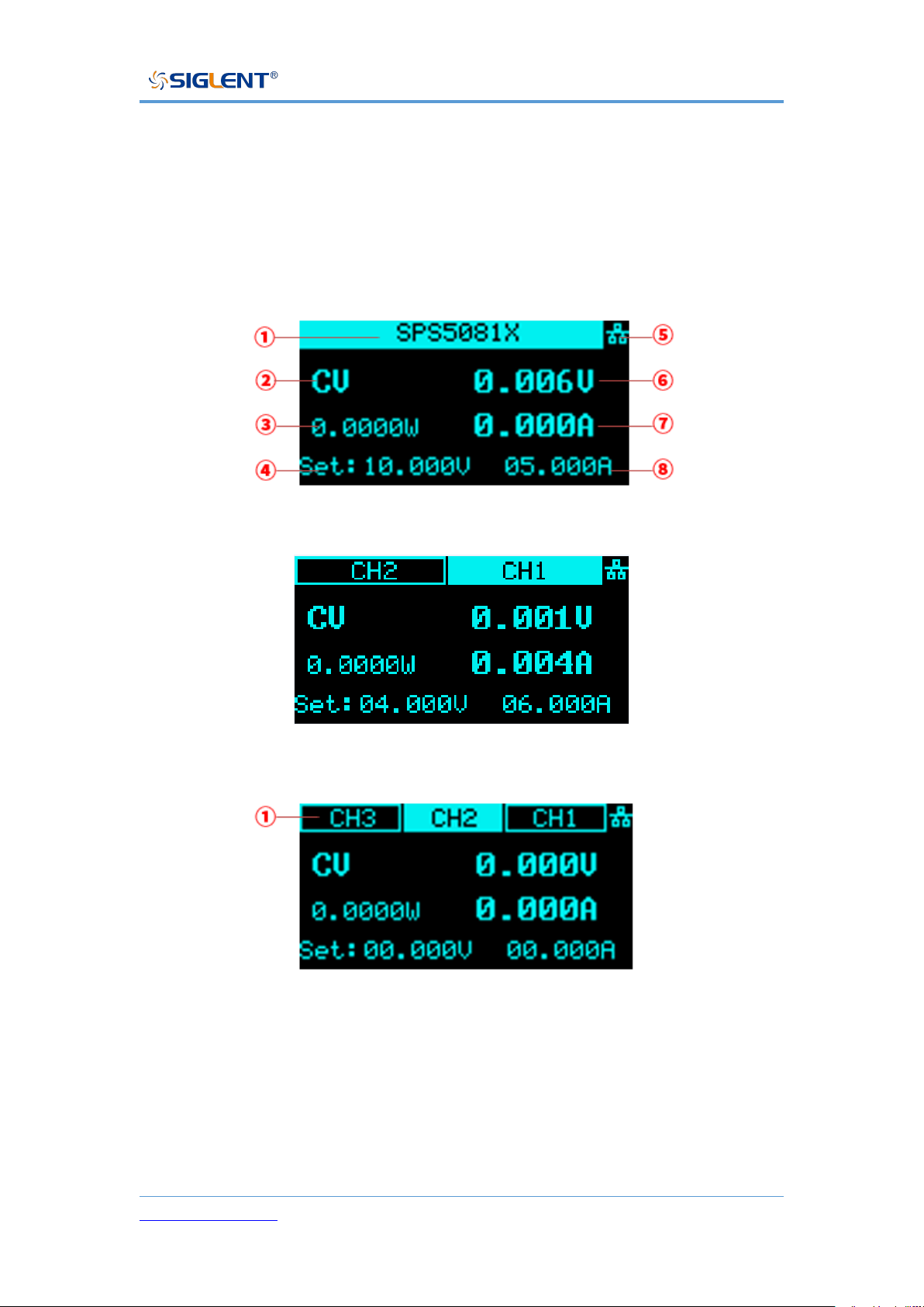
According to different output channels, the SPS5000X series has different user
interfaces.
TypeⅠ/TypeⅡ/TypeⅢ
Type IV
Type Ⅴ:
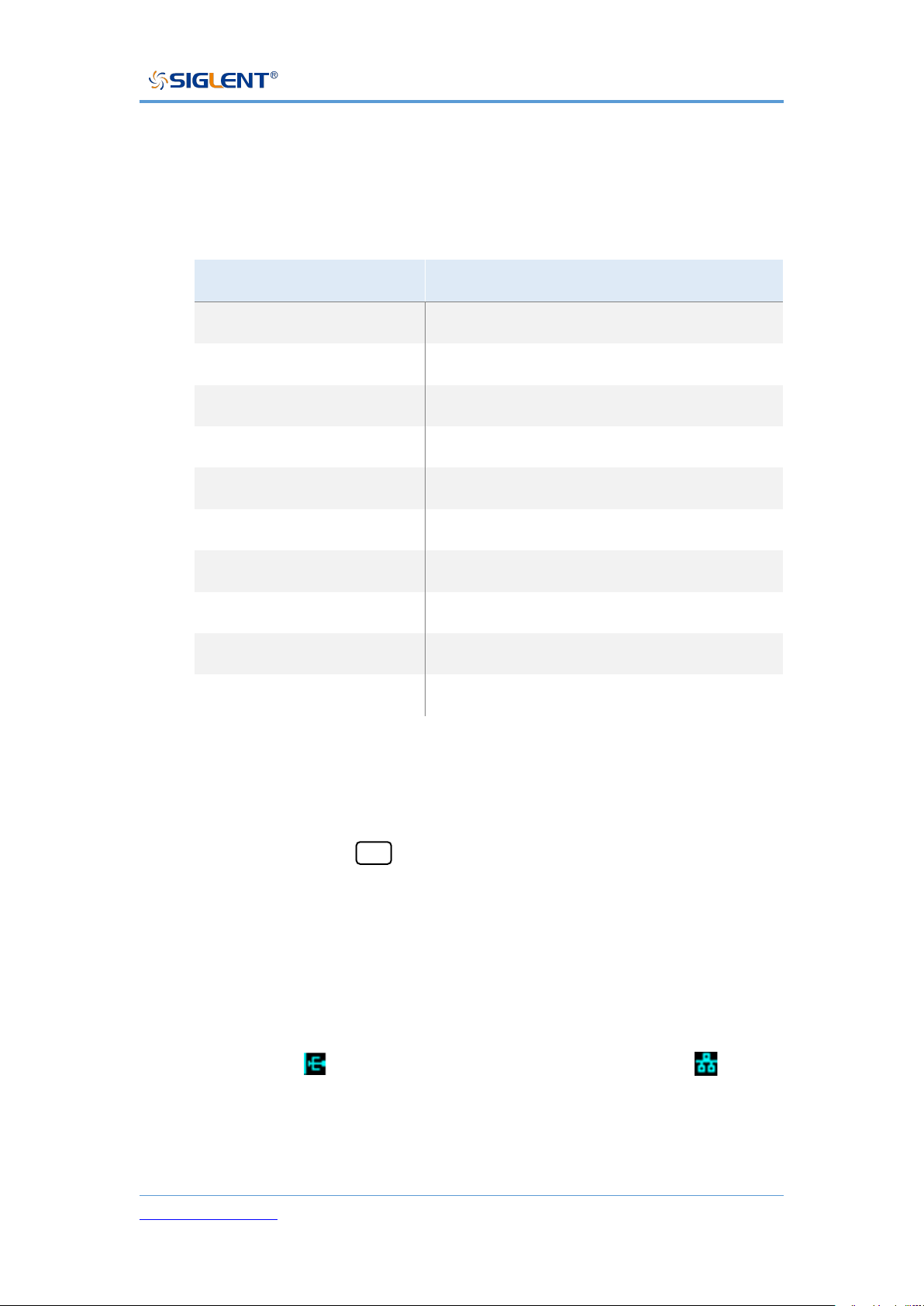
① Type I/Type II/Type III are single-channel models. The status bar here
displays the machine model information. If it is multi-channel, the status
of each channel is displayed here.
Type IV is a dual-channel model: Two channels CH1 and CH2 are
displayed.
Page 46
SPS5000X Series User Manual
WWW.SIGLENT.COM 45
Type V is a three-channel model: Three channels of CH1, CH2, and
CH3 are displayed.
② Display the current status of the power supplies. The symbol display and
meaning of the power supply are as follows:
Symbol
Representation
CV
CV mode
CC
CC mode
Alt
Critical mode
S
Series mode
P
Parallel mode
CV:EXT
External control mode
CC:EXT
External control mode
List:ALT
List: Slave controlled mode
List:CC
List:CC mode
List:CV
List:CV mode
③ Output power value.
④ Voltage setting value, you can set the size of the output voltage value.
Method: Press the Set key to switch the cursor position, press the left
and right direction keys to switch the cursor to the number of digits, turn
the knob to increase or decrease the value, press the knob to confirm,
and the setting is complete.
⑤ Display the status of LAN network port or peripheral USB access. When
the network cable is connected or the U disk is inserted, this place is
highlighted. means that a U disk has been read, and means
that the LAN cable is connected.
⑥ Output voltage value, take the average voltage
Page 47

SPS5000X Series User Manual
WWW.SIGLENT.COM 46
⑦ Output current value, take the average value of current.
⑧ Current setting value, you can set the size of the output current value.
Method: Press the Set key to switch the cursor position, press the
left and right direction keys to switch the cursor to the number of digits,
turn the knob to increase or decrease the value, press the knob to
confirm, and the setting is complete.
Page 48

SPS5000X Series User Manual
WWW.SIGLENT.COM 47
Basic Operation
This chapter will introduce the functions and operation methods of the control
panel of SPS5000X in detail so that you can have a more comprehensive
understanding of the SPS5000X for better work.
System Settings
View Version Information
Operation method: Press menu → 1.System → 1.Version on the panel to
call up the system information interface.
The information that can be viewed on the interface includes: Boot times,
vendor name, model, product specification, serial number, host version, and
slave version.
System Upgrade
Please follow the steps below to upgrade the firmware:
1) Download the firmware upgrade package from the official website.
2) Copy the .ADS file in the upgrade package to the root directory of the U
disk(FAT32).
3) Insert the USB flash disk into the USB port of the front panel.
4) Press Menu → 1.System → 4.Upgrade on the front panel, and select the
upgrade file.
5) Press the button to confirm. The upgrade progress bar will pop up. After the
upgrade is successful, it will restart. If it fails, a prompt box will pop up.
Any operation that interrupts the upgrade process may cause upgrade failure
or even the machine cannot be restarted. Do not remove the USB memory
device or make any changes to the power supply while updating.
Page 49
SPS5000X Series User Manual
WWW.SIGLENT.COM 48
Restore Default
Operation method: After pressing Menu → 1.System → 2.Default Setting
on the front panel, press the knob on the interface, turn the knob to select
and press the knob to confirm, and automatically return to the main interface
after successful setting.
Beeper Setup
Operation method: After pressing Menu → 1.System → 3.Key sound on the
front panel, press the knob on the interface, turn the knob to On, press the knob
to confirm, and the buzzer setting is turned . To set off, press the knob
again to select , press the knob to confirm, and the buzzer setting is off.
Parallel/Series Operation
Parallel or Series among multiple SPS5000X supplies
Two or three power supplies can be connected in series or parallel to extend
the output capabilities.
Setting method: Menu → 1.System → 5.M/S mode settings to enter the
setting interface, press the knob to display a cursor, turn the knob to select the
configuration of the slave/slave mode, and press the knob to make the setting
effective.
One in series: The master is set to Master / Series, and the other slave is set
to Slave / Series.
One in parallel: The master is set to Master / Parallel1 and Slave / Parallel is
set as Slave / Parallel.
Page 50
SPS5000X Series User Manual
WWW.SIGLENT.COM 49
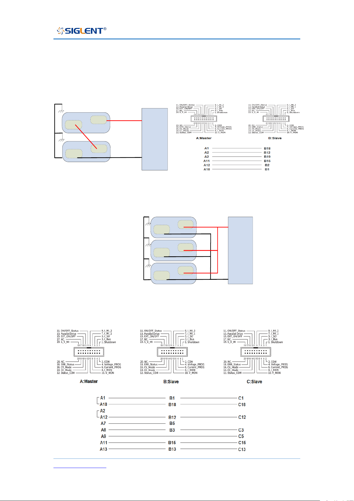
Parallel 2 units: The master set to Master/Parallel2, two slaves set to
Slave/Parallel.
One set in series: Schematic diagram of analog interface wiring.
-
+
Load
-
-
+
+
Master unit
Slave unit
Two units in parallel: Schematic diagram of analog interface wiring.
One unit is connected in parallel, as long as the control line of the second slave
is not connected.
-
+
Load
-
+
Master unit
-
+
Slave unit 1
-
+
Slave unit 2
Page 51
SPS5000X Series User Manual
WWW.SIGLENT.COM 50
Parallel or Series among channels
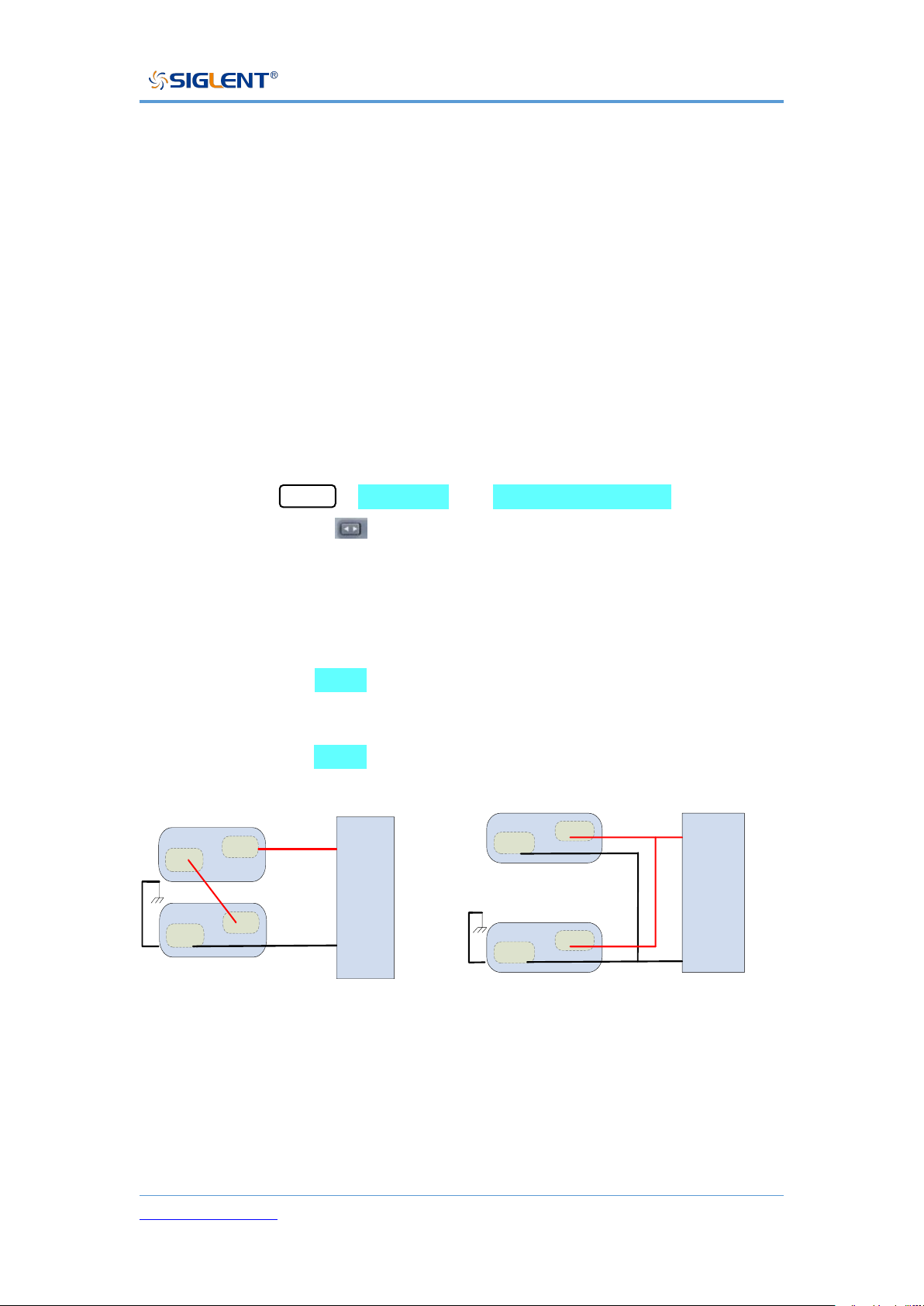
1) The SPS5000X dual-channel model supports two-channel series-parallel
mode and expands the output capabilities.
There are two connection modes of CH1/CH2 series connection and CH1/CH2
parallel connection between the two channels. Only CH1 channel can be used
as the master, and the other channels can be used in slave mode.
Setting method: Menu → 1.System → 5.M/S mode settings to enter the
setting interface, press in the interface to switch between CH1/CH2. After
selecting CH1, press the knob, and turn the knob to select the mode. Press the
knob to confirm.
When CH1 is set to SER , there is no need to set CH2 at this time, and
CH1/CH2 are in series output mode.
When CH1 is set to PAR1 , there is no need to set CH2 at this time, and
CH1/CH2 are in parallel output mode.
-
+
Load
-
-
+
+
SPS5044X
SPS5084X
SPS5164X
CH2
CH1
Dual channel series mode Dual channel parallel mode
2) The SPS5000X three-channel model supports the combination of the
series-parallel mode of CH1, CH2 channels and the combination of CH1,
CH2, CH3 parallel modes, and expands the output.
-
+
Load
-
+
CH2
-
+
CH1
SPS5044X
SPS5084X
SPS5164X
Page 52
SPS5000X Series User Manual
WWW.SIGLENT.COM 51
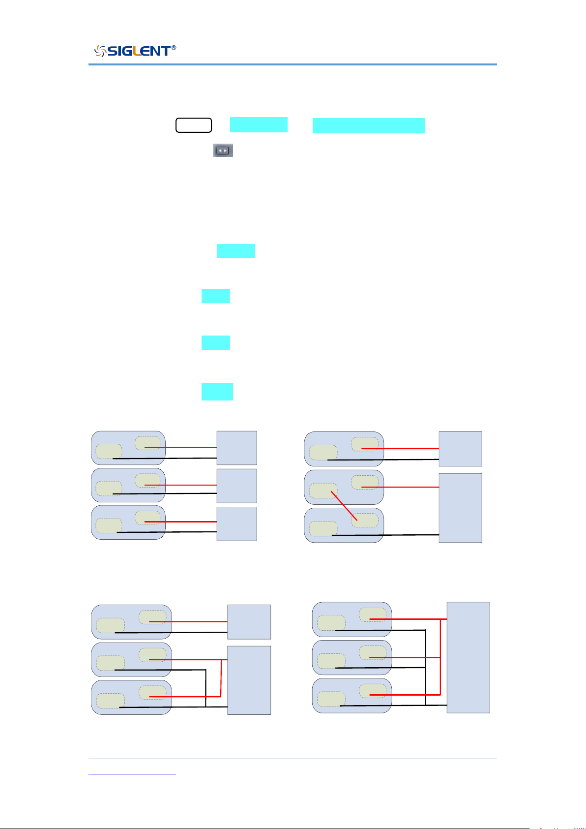
Combination modes between three channels: CH1/CH2/CH3 output separately,
CH1/CH2 in series, CH1/CH2 in parallel, and CH1/CH2/CH3 in parallel.
Setting method: Menu → 1.System → 5.M/S mode settings to enter the
setting interface, press in the interface to switch between CH1/CH2/CH3.
After selecting CH1, press the knob, and turn the knob to select the mode.
Press the knob to confirm and the setting takes effect.
When CH1 is set to Single , each channel of CH1/CH2/CH3 is output
separately.
When CH1 is set to SER , there is no need to set CH2/CH3. At this time,
CH1/CH2 are output in series, and CH3 is output independently;
When CH1 is set to PAR1 , there is no need to set CH2/CH3. At this time,
CH1/CH2 are output in parallel, and CH3 is output independently;
When CH1 is set to PAR2 , there is no need to set CH2/CH3, at this time,
CH1/CH2/CH3 are output in parallel.
-
+
CH3
-
+
CH2
-
+
CH1
SPS5045X
SPS5085X
SPS5165X
Load 3
Load 1
Load 2
CH1/CH2/CH3 independent output CH1 / CH2 in series
-
+
Load 1
-
+
CH3
-
+
CH2
-
+
CH1
SPS5045X
SPS5085X
SPS5165X
Load 2
CH1 / CH2 in parallel CH1 / CH2/CH3 in parallel
-
+
Load 1
-
+
CH3
-
+
CH2
-
+
CH1
SPS5045X
SPS5085X
SPS5165X
Load 2
-
+
Load
-
+
CH3
-
+
CH2
-
+
CH1
SPS5045X
SPS5085X
SPS5165X
Page 53
SPS5000X Series User Manual
WWW.SIGLENT.COM 52
Function Settings
Set List Function
1) Single-channel models
Press the List key directly on the operation panel to enter the List setting
interface, and press the List key again to exit the List mode:
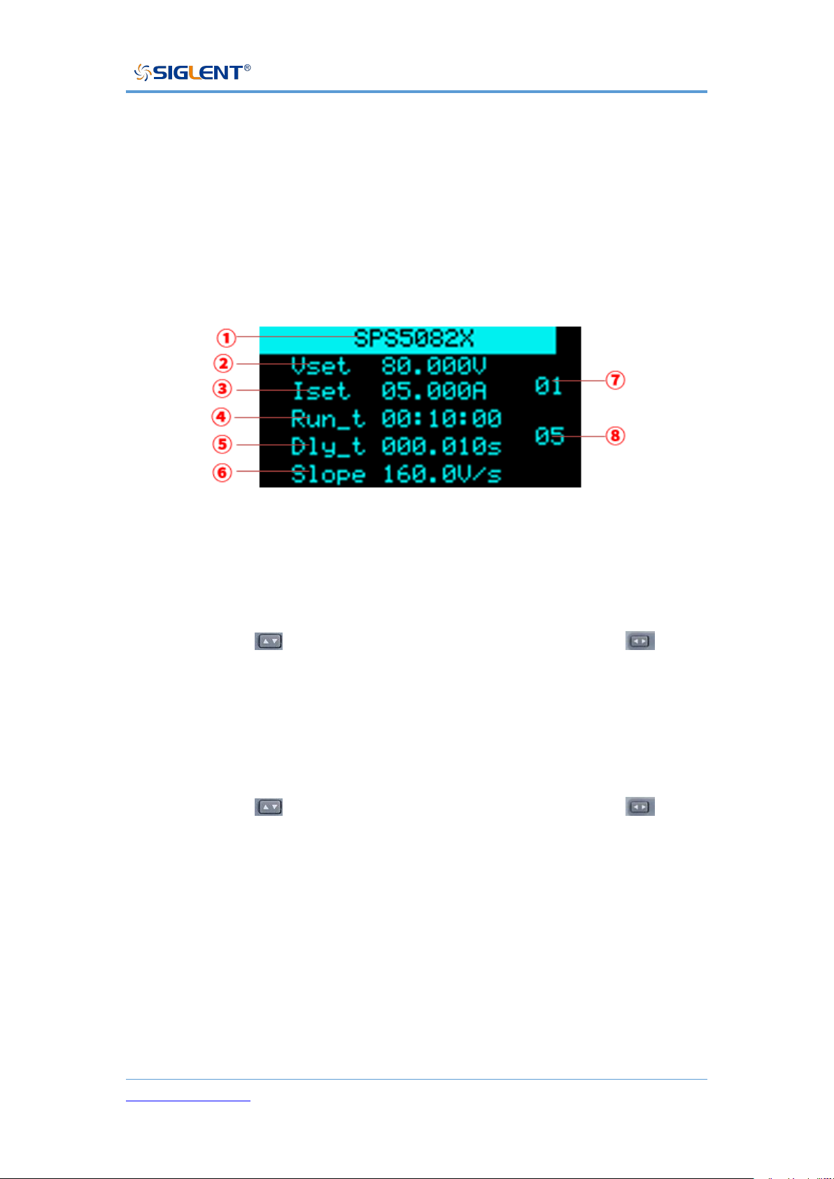
① Display model, not editable.
② Set the output voltage level
Setting method: In the List setting interface, press the knob to display the
cursor, press key to move the cursor to the position, press key to
move the cursor to the digit to be changed, turn the knob to increase or
decrease the value, and press the knob to enter the setting.
③ Set the output current level
Setting method: In the List setting interface, press the knob to display the
cursor, press key to move the cursor to the position, press key to
move the cursor to the digit to be changed, turn the knob to increase or
decrease the value, and press the knob to enter the setting.
④ Single-step running time
Setting method: In the List setting interface, move the cursor to here, turn
the knob to change the level, and press the knob to confirm the setting.
⑤ Output delay time
⑥ Slope level
Page 54
SPS5000X Series User Manual
WWW.SIGLENT.COM 53
When the power supply is set to CC mode priority, here is the current slope.
When set to CV priority, this is the voltage slope.
Setting method: In the List setting interface, move the cursor to here, turn
the knob to change the level, and press the knob to confirm the setting.
⑦ Number of List groups in the current setting interface, 01 means the first
group
Setting method: In the List setting interface, press the key when the cursor
is hidden to switch the current group number interface.
⑧ Total number of steps, the total number of steps output by List, 05 means
there are 5 sets of data
Setting method: In the List setting interface, move the cursor to here, turn
the knob to change the value, and press the knob to confirm.
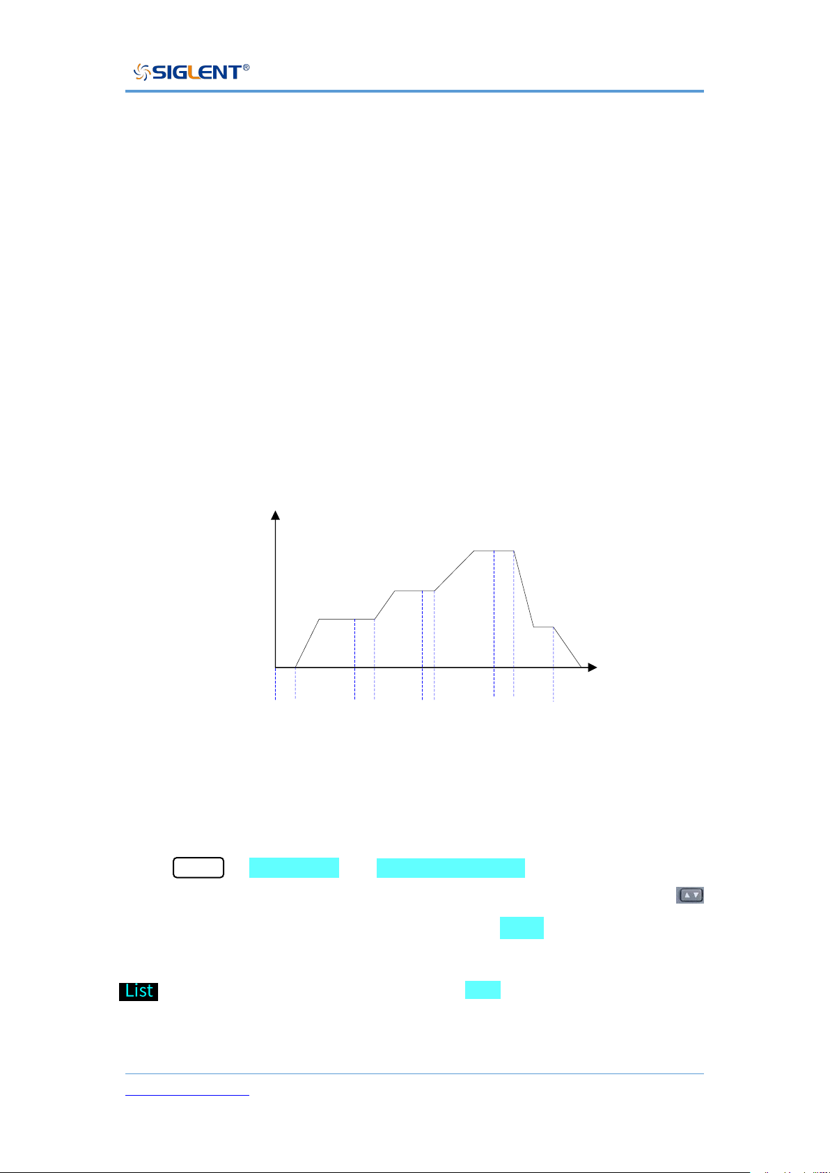
V(V)
T
0
delay1 Run time1 delay2 Run time2 delay3
Run time3
delay4 Run time4 OFFON
List mode
2) Multi-channel model
To set the List output, first set the channel mode to List mode. Setting method:
Press Menu → Configure → 10.Channel Mode to enter the setting
interface. When the cursor is hidden, press the left and right direction keys
to switch the channel to be set CH1/CH2/ CH3. CH1 means that the CH1
channel is currently selected. Press the knob and then turn the knob to select
. Press the knob. When it is displayed as List , the channel List mode is
set successfully.
Page 55
SPS5000X Series User Manual
WWW.SIGLENT.COM 54
For other settings, refer to the single-channel output model method. During List
output, press the knob to pause the time, and press the knob again to continue
the output countdown.
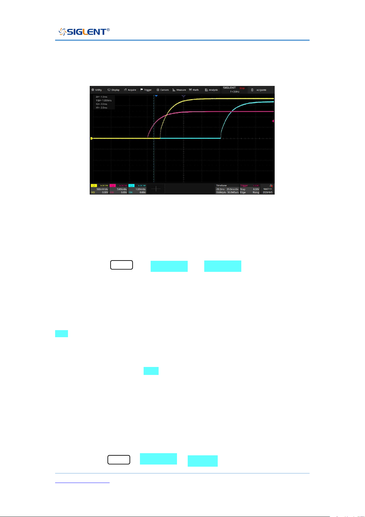
3-channel List mode output example
Set OCP/OVP
Setting method: Menu → Configure → 1.Protect , enter the setting
interface. After pressing the knob, press the up and down direction keys to move
the cursor, select the knob to change the value, and press the knob to confirm
the setting takes effect.
OCP has added the switch OCP function option key. When it is displayed as
On , it means that the OCP function is on. Setting method: Press the knob on
the setting interface, move the cursor to the shadow overlay On/Off, turn the
knob to select On or Off, press the knob to confirm and the setting will take
effect. When the display is Off , it means that the OCP function is turned off
and the power supply will not trigger over-current protection.
Set Bleeder Resistor Control
Setting method: Menu → Configure → 2.Shunt , enter the setting interface.
Page 56

SPS5000X Series User Manual
WWW.SIGLENT.COM 55
Press the knob in the interface, turn the knob to switch the Off/On options, press
the knob to confirm and the setting takes effect.
Set CC/CV Priority
The SPS5000X operation mode can be set to select CC high-speed priority, CC
slope priority, CV high-speed priority, and CV slope priority. High-speed priority
makes the voltage and current change at the fastest rate, and slope priority
makes the power supply change in voltage and current at a specified slope.
Setting method: Menu → 3.Operating Mode to proceed to the next submenu
interface.
Press the knob to enter the 1.Mode interface , and you can select the CC/CV
mode. After pressing the knob, turn the knob to switch between CC or CV. Press
the knob to confirm and the setting takes effect. When CC is displayed, it
means that it is currently in CC mode. Press Esc to return to the previous
menu.
Turn the knob to 2.Priority mode and press the knob to enter, you can set the
mode as high-speed priority or slope priority. The setting method is the same
as above, and the setting takes effect after pressing the knob to confirm. When
High Speed is displayed, it means that the current mode is high-speed priority
mode, and the slope cannot be edited in this mode. Press Esc to return to
the previous menu.
When set to slope priority mode, press the knob to enter the 3.Slew value
interface, you can set the voltage rise/fall slope or current rise/fall slope.
Page 57
SPS5000X Series User Manual
WWW.SIGLENT.COM 56
Set Output On/Off Delay Time
The SPS5000X can be set to turn on the output delay function and turn off the
output delay function.
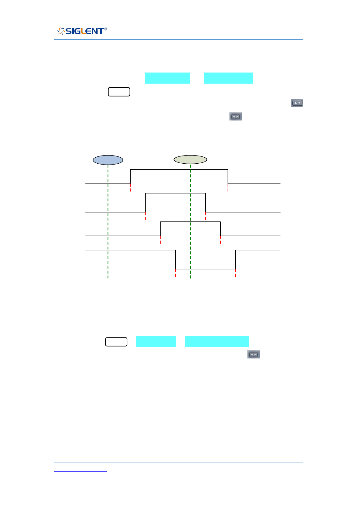
Setting method: menu → 2.Configure → 4.Output delay to enter the
setting interface. In the interface, press the knob to display a cursor, press
to switch the setting of on delay or off delay, press key to switch the
number of digits, and turn the knob to change the value. After the setting is
completed, you need to press the knob to confirm.
ON
OFF
1#
SPS5000X
2#
SPS5000X
3#
SPS5000X
4#
SPS5000X
T1_ON_Delay
T1_OFF_Delay
T2_ON_Delay T2_OFF_Delay
T3_ON_Delay T3_OFF_Delay
T4_ON_Delay
T4_OFF_Delay
Set Internal Resistance
Setting method: Menu → 2.Configure →5.Output resistance Enter the setting
interface. Press the knob to display the cursor. Press the key to switch the
digit where the cursor is located. Turn the knob to increase or decrease the
value. After the setting is completed, you need to press the knob to confirm it to
take effect.
Different types of power supplies can be set with different internal resistance
values, see the previous chapter 6.5 for details.
Page 58
SPS5000X Series User Manual
WWW.SIGLENT.COM 57
Set Measurement Accuracy
The SPS5000X has three measurement accuracy modes to choose from: Low,
Mid and High. When Low is selected, the measurement rate is the fastest but
has less accuracy. High is the slowest measurement, but more accuracy. High
is selected by default.
Setting method: Menu → 2.Configure → 6.Measure average to enter the
setting interface. Press the knob in the interface, turn the knob to switch the
cursor, press the knob to confirm and the setting takes effect.
External Analog Control
Four working modes of voltage control voltage, voltage control current,
resistance control voltage, and resistance control current can be realized
through the ports on the rear panel. In the external voltage control mode, an
adjustable voltage of 0-10 V is connected to the input terminal to simulate the
output from 0 to full-scale, to adjust the value of the voltage and current output
by the power supply (10 V corresponds to the voltage or current value of the
full-scale of the power supply).
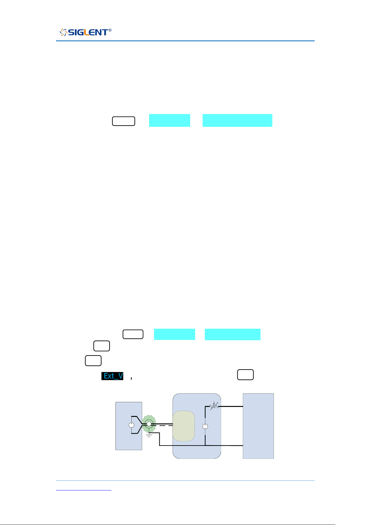
◆ External voltage control voltage output
Setting method: Menu → 2.Configure → 7.Voltage control, press the knob
or the Set button to enter the setting interface, then press the knob or
the Set button to enter the selection, and press the knob or turn the knob
to select and then press the knob or the Set button to confirm .
Load
DC
SPS5000X
+
-
Analog
connector
DC
V_PROG_
Voltage
0-10V
2 core shielded
wire or twisted pair
2
4
External voltage control voltage output
Page 59
SPS5000X Series User Manual
WWW.SIGLENT.COM 58
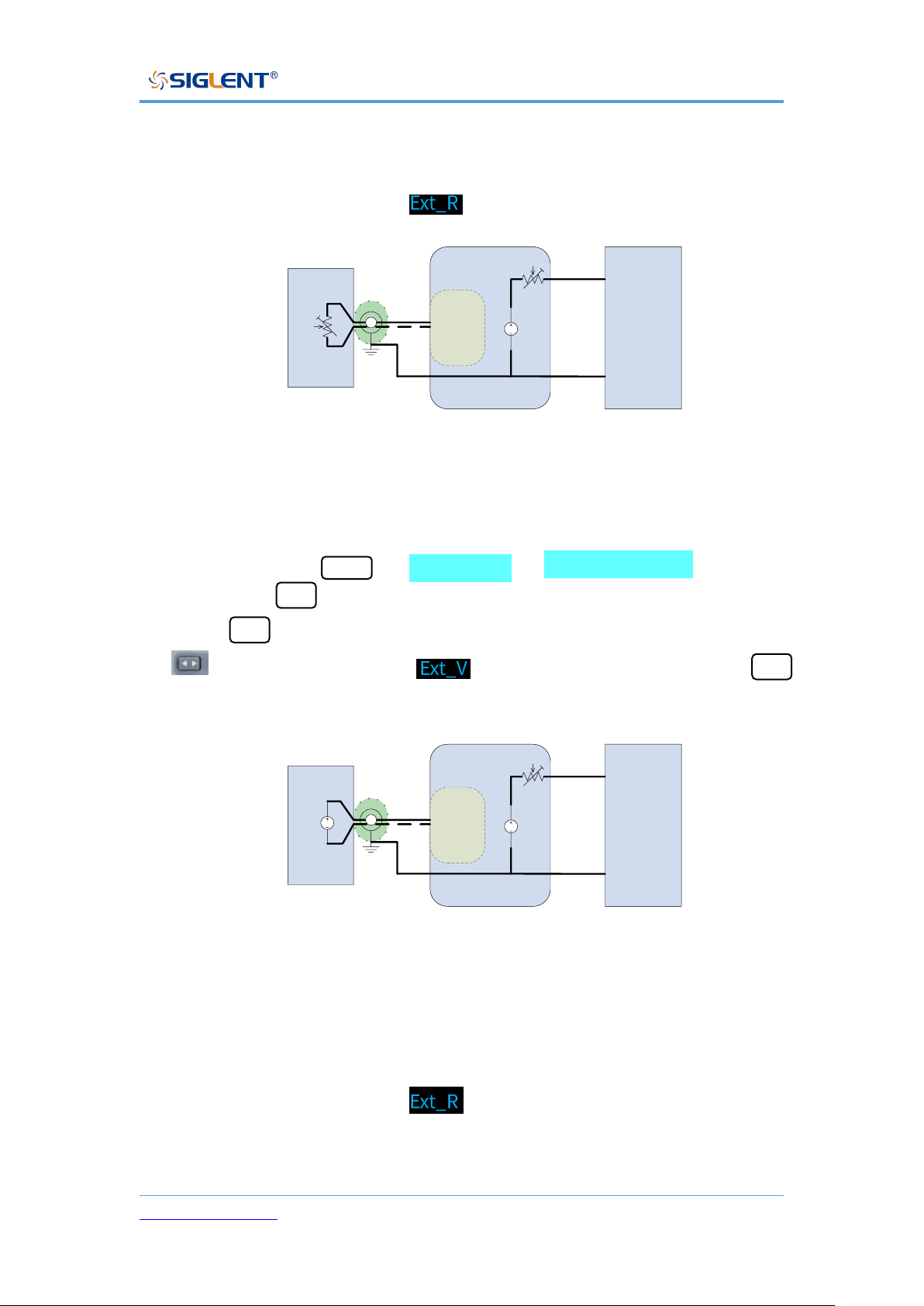
◆ External resistance control voltage output:
The operation method is the same as (external voltage control voltage
output), select and confirm
Load
DC
SPS5000X
+
-
Analog
connector
R_PROG_
Voltage
0-10K
2 core shielded
wire or twisted pair
2
4
External resistance control voltage output
◆ External voltage control current output:
Setting method: Menu → 2.Configure → 8.Current control , press the
knob or the Set button to enter the setting interface, then press the knob
or the Set button to enter the selection, and then press the knob or the
to set button to select , and then press the knob or the Set
button to confirm .
Load
DC
SPS5000X
+
-
Analog
connector
DC
V_PROG_
Current
0-10V
2 core shielded
wire or twisted pair
2
6
External voltage control current output
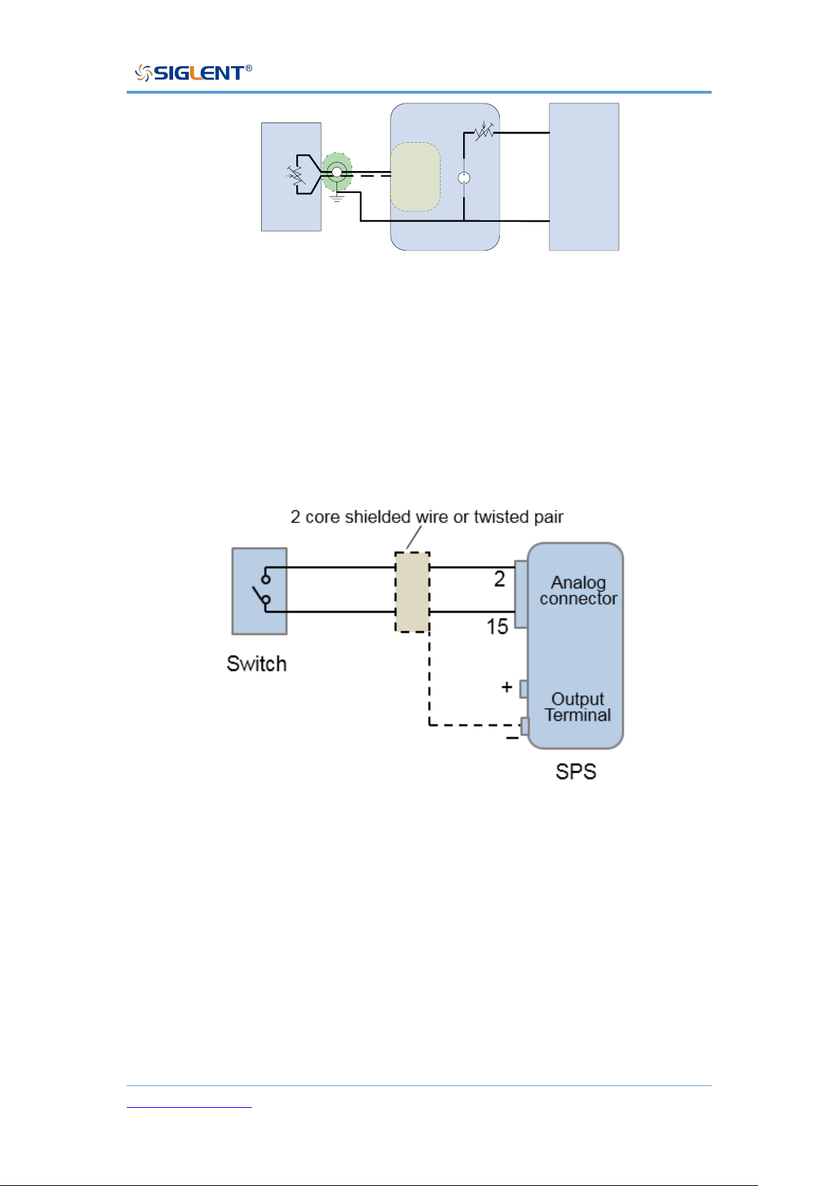
◆ External resistance control current output:
The operation method is the same as (external voltage control current
output), select and confirm .
Page 60
SPS5000X Series User Manual
WWW.SIGLENT.COM 59
Load
DC
SPS5000X
+
-
Analog
connector
R_PROG_
Current
0-10K
2 core shielded
wire or twisted pair
2
6
External resistance control current output
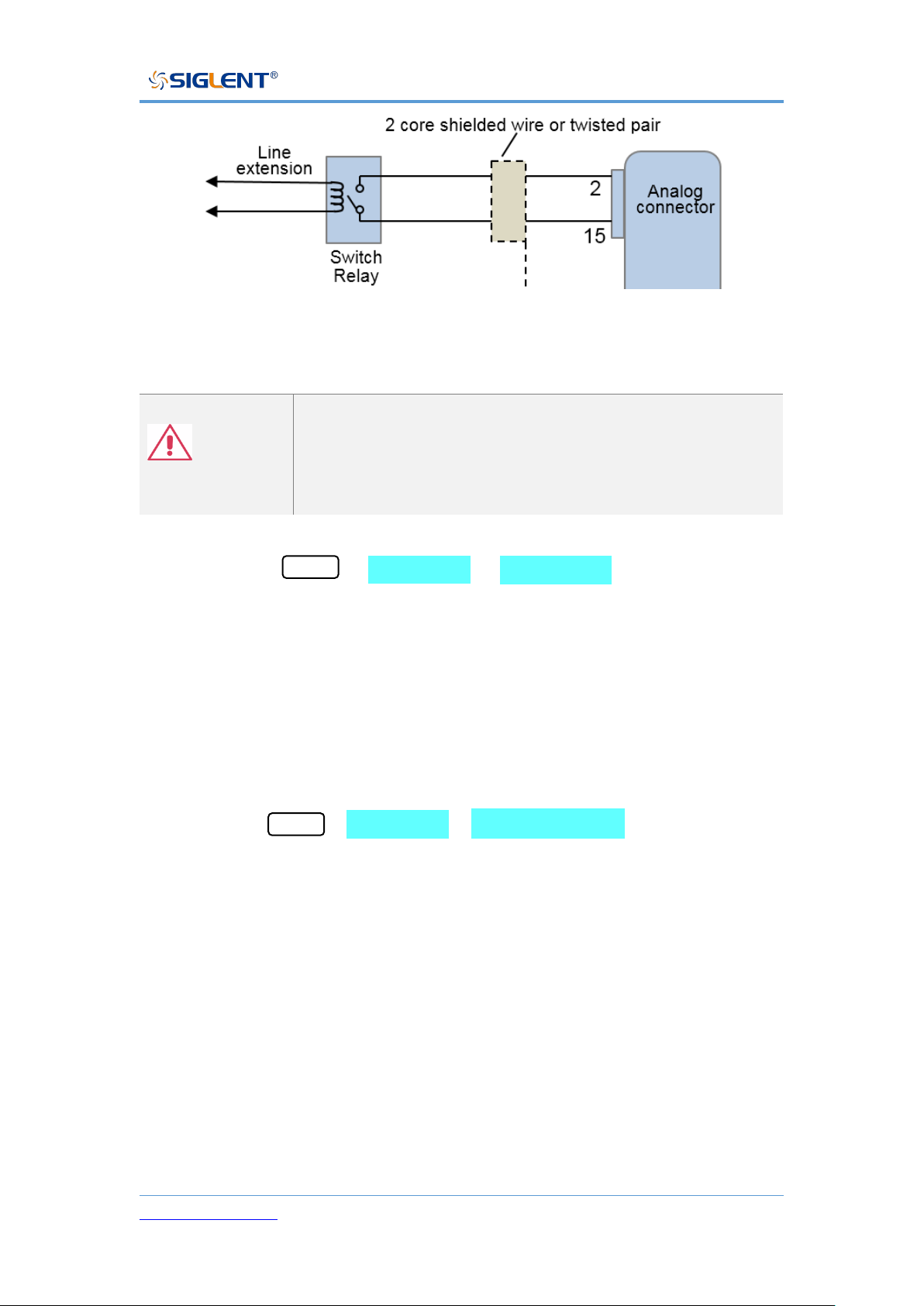
External Control Output On/Off
When set to ON, the Output button on the front panel is invalid. The output is
controlled by the rear analog interface pin15 low-level effective control, and the
reference ground is pin 2 (COM).
External control output on / off
When using the switch remotely, please use the switch relay to extend the
circuit
Page 61
SPS5000X Series User Manual
WWW.SIGLENT.COM 60
Use relay switch
Note
If you use a switch to control multiple instruments, make
sure that each instrument is independent and use a relay
to complete the operation.
Setting method: Menu → 2.Configure → 9.Ext on/off to enter the setting
interface. After pressing the knob, turn the knob to switch On/Off. Press the
knob to confirm and the setting takes effect.
Multi-channel Settings
For models with multiple output channels, the channel mode can be set.
Setting method: Menu → 2.Configure → 10. Channel Mode to enter the setting
interface. In the interface, press the key to switch the channel selection. Press
the knob and then turn the knob to switch the channel selection mode. Press
the knob to confirm and the setting takes effect.
Off: The channel is closed. When the output is turned on, the channel in
the Off state has no voltage or current output。
Normal: The channel is in the normal state. When the output is turned on,
each channel outputs according to the set voltage and current。
List: List mode. After the channel is set to List mode, when the output is
Page 62
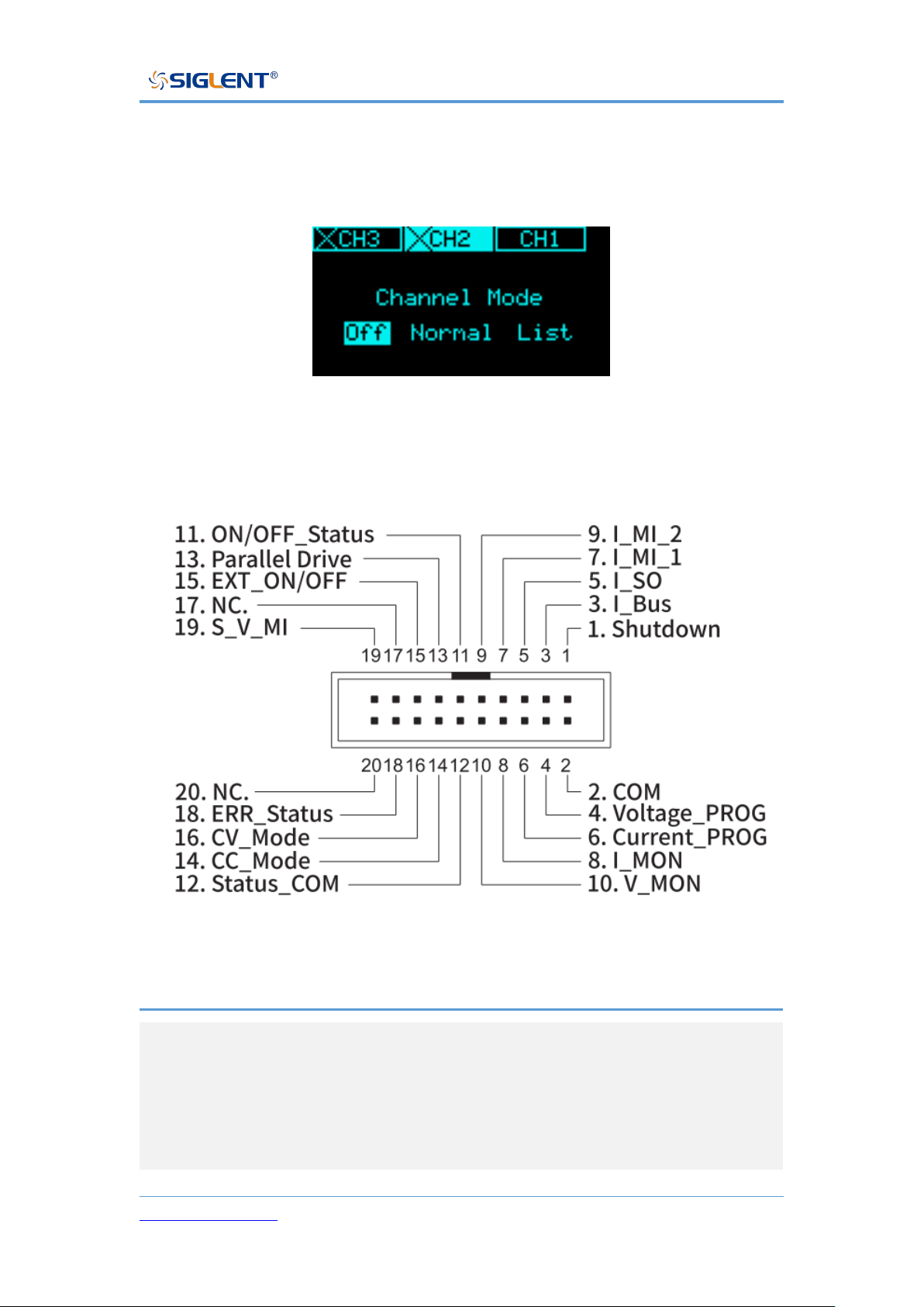
SPS5000X Series User Manual
WWW.SIGLENT.COM 61
turned on, the channel outputs according to the voltage and current
values set by the List.
The figure shows that the CH2 and CH3 channels are Off.
Analog Interface
Pin Number
Description
01
The shutdown signal will turn off the output when a low TTL
signal is applied.
The shutdown signal is pulled up to 5V with a 10kΩ pull-up
resistor.
Page 63
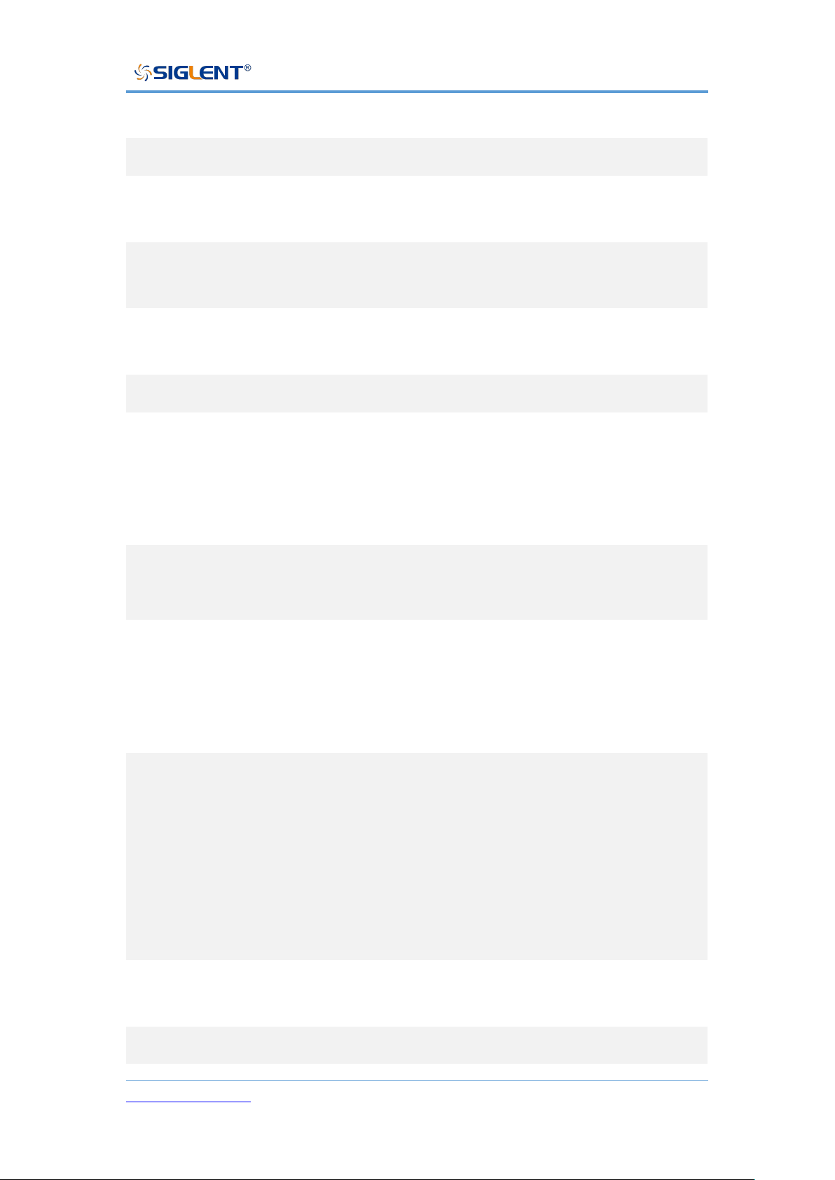
SPS5000X Series User Manual
WWW.SIGLENT.COM 62
03
Used when operating 2 or more units in parallel.
05
Current sum output signal when used in parallel mode.
07
Master unit current sum input signal from the first slave
CURRENT SUM OUTPUT. Used in parallel mode only.
09
Master unit current sum input signal from the second slave
CURRENT SUM OUTPUT. Used in parallel mode only.
11
Turns on when the output has been turned on. (photo
coupled open collector output)
13
Parallel control signal during master-slave parallel operation.
15
Turns the output on/off when (default setting) a low TTL
signal is applied.
Internally, the circuit is pulled up to +5 V with 10 kΩ
resistance.
19
Series slave input during master-slave series operation.
(40 V/80 V/160 V models only)
02
Control signal common. Connected to the sense terminal
when remote sense is used.
Connected to the negative output terminal when remote
sense is not used.
04
External voltage control of the voltage output.
A voltage of 0~10 V is used to control the full-scale voltage
output (0%~100%) of the instrument.
External resistance control of the voltage output.
A resistance of 0 kΩ ~ 10 kΩ is used to control the full-scale
voltage output (0%~100%) of the instrument.
04,02
When connecting the external voltage source to the MIL
connectors, use shielded or twisted paired wiring.
06
External voltage control of the current output.
Page 64
SPS5000X Series User Manual
WWW.SIGLENT.COM 63
A voltage of 0~10V is used to control the full-scale current
output (0%~100%) of the instrument
External resistance control of the current output.
A resistance of 0kΩ ~ 10kΩ is used to control the full-scale
current output (0%~100%) of the instrument.
08
Current Monitor Output. Outputs the full-scale current
(0~100%) as a voltage (0V~10V).
10
Voltage Monitor Output. Outputs the full-scale voltage
(0~100%) as a voltage (0V~10V).
12
Common for status signals 14, 16, and18.
14
Turns on when CC mode is active. (photo coupled open
collector output)
16
Turns on when CV mode is active. (photo coupled open
collector output)
18
Turns on when any of the protection modes are tripped (OVP,
OCP) or if a shutdown signal is received. (photo coupled
open collector output)
Communication interface settings
◆ USB
USB cannot be edited, only viewing operations can be performed.
Operation method: Menu → 3.Communication → 1.USB . After
entering the interface, you can view the resource information of the USB
device.
Page 65
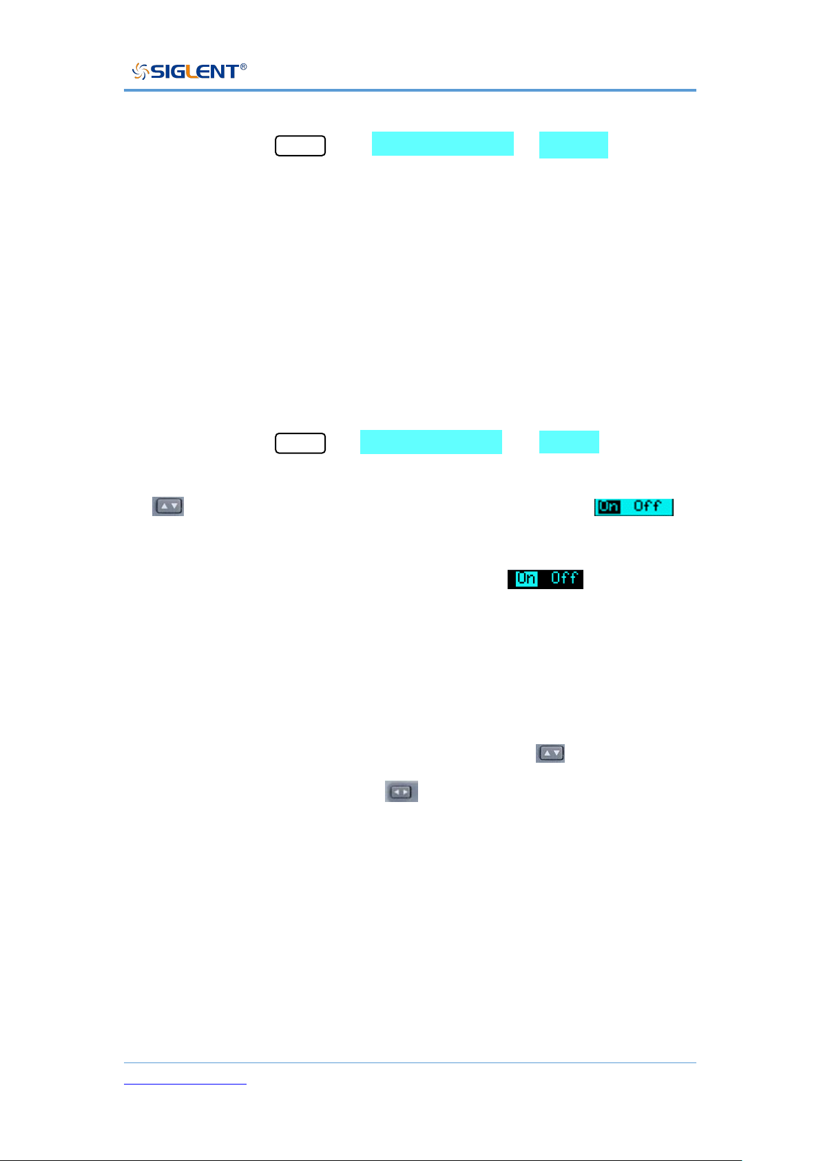
SPS5000X Series User Manual
WWW.SIGLENT.COM 64
◆ GPIB
Setting method: Menu → 3. Communication → 2. GPIB enters the
setting interface, press the knob to display a cursor, turn the knob to change
the value, and press the knob to make the setting effective.
◆ LAN
SPS5000X supports DHCP function, users can set to obtain IP
automatically or set IP manually. You can set the DHCP switch, IP address,
gateway address, and subnet mask address.
Setting method: Menu → 3. Communication → 3.LAN to enter the
LAN setting interface. Press the knob to display the cursor position, press
to move the cursor position up and down. When is
displayed, it means that the selection is On, turn the knob to switch On/Off,
and press the knob to confirm the effect. When is displayed, it
means that DHCP is set to On, and the IP is automatically obtained at this
time.
If you want to set the IP manually, first set DHCP to Off according to the
above method. After pressing the knob, press the key to move the
cursor up and down, press the key to move the cursor left and right,
turn the knob to change the value, and press the knob to confirm the setting
takes effect.
Page 66

SPS5000X Series User Manual
WWW.SIGLENT.COM 65
Remote Control
The SPS5000X supports communication with a computer via USB, LAN, and
GPIB-USB interfaces using a SCPI (Standard Commands for Programmable
Instruments) compliant command set.
This chapter will introduce how to build a programming environment and explain
the SCPI commands supported by the SPS5000X.
Way to Control
Using NI-VISA
Users can realize remote control of the instrument by using NI-VISA of NI
(National Instrument Corporation). Regarding NI-VISA, there is a complete and
real-time version (Run-Time Engine version). The complete version includes NI
device drivers and a tool called NI MAX. NI MAX is a user interface used to
control the device. The real-time version is much smaller than the full version,
and it only includes NI device drivers.
After installing NI-VISA, use a USB cable to connect the SPS5000X (via the
USB Device interface on the rear panel) to the computer, or use a network cable
to connect the SPS5000X (via the LAN interface on the rear panel) to the local
area network where the computer is located.
Based on NI-VISA, users can remotely control SPS5000X in two ways, one is
through web service; the other is custom programming combined with SCPI
commands. For more information, please refer to the programming examples.
Using Sockets
Page 67

SPS5000X Series User Manual
WWW.SIGLENT.COM 66
Users can also use Sockets to communicate with SPS5000X based on the
TCP/IP protocol through the network port. Socket communication is a basic
communication technology of computer networks, which allows applications to
communicate through network hardware and standard network protocol
mechanisms built into the operating system. This method requires two-way
communication between the instrument and the computer network through an
IP address and a fixed port number.
The port of SPS5000X for Socket communication is 5025.
After connecting the SPS5000X (via the LAN interface on the rear panel) to the
local area network where the computer is located with a network cable, the user
can combine SCPI commands for custom programming to realize remote
control of the SPS5000X. For more information, please refer to the
programming examples.
Grammatical Conventions
SCPI commands are a tree-like hierarchical structure, including multiple
subsystems. Each subsystem is composed of a root keyword and one or
several hierarchical keywords. Command keywords are separated by colons ‘: ’,
keywords are followed by optional parameter settings, commands and
parameters are separated by ‘spaces’, for multiple parameters, parameters are
separated by commas‘, ’. A question mark ‘?’ is added after the command line,
which means to query this function.
Most SCPI commands are a mixture of upper and lower case letters. Capital
letters indicate the abbreviations of commands, namely short commands. If you
want better program readability, you can use long commands. E.g:
Page 68

SPS5000X Series User Manual
WWW.SIGLENT.COM 67
Among them, the keyword VOLTage. You can enter VOLT or VOLTage, and
combine upper and lower case letters at will. Therefore, VolTaGe, volt, and Volt
are all acceptable. Other formats (such as VOL and VOLTAG) will produce
errors.
⚫ Braces ({ }) enclose the parameter selection. The braces are not sent with
the command string.
⚫ The vertical line (|) divides the parameter selection.
⚫ Angle brackets (< >) indicate that a value must be assigned to the
parameter inside the bracket. The angle brackets are not sent with the
command string.
⚫ Optional parameters are enclosed in square brackets ([ ]). If you do not
specify a value for the optional parameter, the instrument will use the
default value. For example, the [:SET] in the above command can be
omitted (for example: ‘VOLT? CH1’), and the command will operate on the
current channel. The square brackets are not sent with the command string.
Command Summary
1) IEEE Common Command Subsystem.
2) Measure Command Subsystem.
3) Configure Configuration Command Subsystem.
4) List Configuration Command Cubsystem.
5) System Configuration Command Subsystem.
Page 69

SPS5000X Series User Manual
WWW.SIGLENT.COM 68
Command Description
IEEE Common Command Subsystem
*IDN?
Command format: *IDN?
Description: Get device information string (return string content includes:
manufacturer, device model, device serial port number, software version
number)
E.g: *IDN?
Response: Siglent Technologies,SPS5082X,SPS5X2006005,3.1.1.5\n
*RST
Command format: *RST
Description: Restore the state of the device to the initial state.
E.g: *RST
*CLS
Command format: *CLS
Description: Clear the values of all event registers and clear the error list
at the same time
E.g: *CLS
*ESE
Command format: *ESE <number>
Description: Set the enable value of the standard event status register
E.g: *ESE 16
*ESE?
Command format: *ESE?
Description: Query the enable value of the standard event status register.
Page 70

SPS5000X Series User Manual
WWW.SIGLENT.COM 69
E.g: *ESE?
Response: 64
*ESR?
Command format: *ESR?
Description: Query and clear the event value of the standard event status
register.
E.g: *ESR?
Response: 0
*OPC
Command format: *OPC
Description: Operation complete.
E.g: *OPC
*OPC?
Command format: *OPC?
Description: Query whether the current operation is complete.
E.g: *OPC?
Response: 1
*SRE
Command format: *SRE<number>
Description: Set the enable value of the status byte register
E.g: *SRE 24
*SRE?
Command format: *SRE?
Description: Query the enable value of the status byte register
Page 71

SPS5000X Series User Manual
WWW.SIGLENT.COM 70
E.g: *SRE?
Response: 24
*STB?
Command format: *STB?
Description: Query the event value of the status byte register
E.g: *STB?
Response: 72
*TST?
Command format: *TST?
Description: Query the result of instrument self-test
E.g: *TST?
Response: 0
*WAI
Command format:
Description: Wait for all outstanding operations to complete before
executing any other commands
E.g:
Measure Command Subsystem
Set voltage value
Command format: [:SOURce]:VOLTage[:SET] (CHn),{<value> | MINimum | MAXimum
|DEFault}
Description: Set the voltage value of the selected channel
E.g: :SOURce:VOLTage:SET CH1,3
Description: Set the CH1 channel voltage value to 3V
Page 72

SPS5000X Series User Manual
WWW.SIGLENT.COM 71
Command format: [:SOURce]:VOLTage[:SET]? (CHn)
Description: Get the set voltage value of the selected channel
E.g: :SOURce:VOLTage:SET? CH1
Response: 3.000000\n
Obtain the measured voltage value
Command format: MEASure:VOLTage? (CHn)
Description: Get the voltage measurement value of the selected channel
E.g: MEASure:VOLTage? CH1
Response: 2.991442\n
Set current value
Command format: [:SOURce]:CURRent[:SET] (CHn),{<value> | MINimum | MAXimum
|DEFault}
Description: Set the current value of the selected channel
E.g: :SOURce:CURRent:SET CH1,2
Description: Set the CH1 channel current value to 3V
Command format: [:SOURce]:CURRent[:SET]? (CHn)
Description: Get the set current value of the selected channel
E.g: :SOURce:CURRent:SET? CH1
Response: 2.000000\n
Obtain the measured current value
Command format: MEASure:CURRent? (CHn)
Description: Get the current measurement value of the selected channel
E.g: MEASure:CURRent? CH1
Response:1.999407\n
Get power measurement
Command format: MEASure:POWER? (CHn)
Description: Get the electrical power measurement value of the selected
channel
Page 73

SPS5000X Series User Manual
WWW.SIGLENT.COM 72
E.g: MEASure:POWER? CH1
Response:19.959515\n
Get the running status of the channel
Command format: MEASure[:RUN]:MODE? (CHn)
Description: Get the running status of the selected channel
E.g: MEASure:RUN:MODE? CH1
Response: CV\n
Configure Configuration Command Subsystem
Set OVP value
Command format: [:SOURce]:OVP (CHn) ,{<value> | MINimum | MAXimum |DEFault}
Description: Set the overvoltage value of the selected channel
E.g: :SOURce:OVP CH1,8
Description: Set the OVP value of CH1 channel to 8V
Command format: [:SOURce]:OVP? (CHn)
Description: Get the overvoltage value of the selected channel
E.g: :SOURce:OVP? CH1
Response: 15.000000\n
Set OCP value
Command format: [:SOURce]:OCP (CHn) ,{<value> | MINimum | MAXimum |DEFault}
Description: Set the overcurrent value of the selected channel
E.g: :SOURce:OCP CH1,8
Description: Set the OCP value of CH1 to 8A
Command format: [:SOURce]:OCP? (CHn)
Description: Get the overcurrent value of the selected channel
E.g: :SOURce:OCP? CH1
Response: 8.000000\n
Page 74

SPS5000X Series User Manual
WWW.SIGLENT.COM 73
Set OCP switch state
Command format: SYStem:OCP:STATe {ON | OFF | 0 | 1}
Description: Set the ocp switch state of the selected channel
E.g: SYStem:OCP:STATe CH1, 1
Description: Set to open OCP function
Command format: SYStem:OCP:STATe? (CHn)
Description: Get the ocp switch status of the selected channel
E.g: SYStem:OCP:STATe? CH1
Response: 1\n
Set the voltage rise slope
Command format: [:SOURce]:VOLTage:RISE:SLOPe (CHn) ,{<value> | MINimum |
MAXimum |DEFault}
Description: Set the voltage rise slope value of the selected channel
E.g: :SOURce:VOLTage:RISE:SLOPe CH1,8
Description: Set the voltage rising slope of CH1 channel to 8V/s
Command format: [:SOURce]:VOLTage:RISE:SLOPe? (CHn)
Description: Get the voltage rise slope value of the selected channel
E.g: :SOURce:VOLTage:RISE:SLOPe? CH1
Response: 23.000000\n
Set the voltage drop slope
Command format: [:SOURce]:VOLTage:FALL:SLOPe (CHn) ,{<value> | MINimum |
MAXimum |DEFault}
Description: Set the voltage drop slope value of the selected channel
E.g: :SOURce:VOLTage:FALL:SLOPe CH1,8
Description: Set the voltage drop slope of CH1 channel to 8V/s
Command format: [:SOURce]:VOLTage:FALL:SLOPe? (CHn)
Description: Get the voltage drop slope value of the selected channel
E.g: :SOURce:VOLTage:FALL:SLOPe? CH1
Response:10.000000\n
Page 75

SPS5000X Series User Manual
WWW.SIGLENT.COM 74
Set current rising slope
Command format: [:SOURce]:CURRent:RISE:SLOPe (CHn) ,{<value> | MINimum |
MAXimum |DEFault}
Description: sSet the current rising slope value of the selected channel
E.g: :SOURce:CURRent:RISE:SLOPe CH1,8
Description: Set the current rising slope of CH1 channel to 8A/s
Command format: [:SOURce]:CURRent:RISE:SLOPe? (CHn)
Description: Get the current rising slope value of the selected channel
E.g: :SOURce:CURRent:RISE:SLOPe? CH1
Response:8.000000\n
Set current falling slope
Command format: [:SOURce]:CURRent:FALL:SLOPe (CHn) ,{<value> | MINimum |
MAXimum |DEFault}
Description: Set the current falling slope value of the selected channel
E.g: :SOURce:CURRent:FALL:SLOPe CH1,10
Description: Set the current falling slope of CH1 channel to 10A/s
Command format: [:SOURce]:CURRent:FALL:SLOPe? (CHn)
Description: Get the current falling slope value of the selected channel
E.g: :SOURce:CURRent:FALL:SLOPe? CH1
Response:13.000000\n
Set the voltage response change mode
Command format: [:SOURce]:VOLTage[:RESPonse]:MODE (CHn), {FAST| SLOPE}
Description: Set the voltage response change mode of the selected
channel (FAST / SLOPE)
E.g: :SOURce:VOLTage:RESPonse:MODE CH1, FAST
Description: Set the voltage response of CH1 channel to FAST (fast
priority) (set to CV mode available)
Command format: [:SOURce]:VOLTage[:RESPonse]:MODE? (CHn)
Description: Get the voltage response change mode of the selected
channel
Page 76

SPS5000X Series User Manual
WWW.SIGLENT.COM 75
E.g: :SOURce:VOLTage:RESPonse:MODE? CH1
Response: Slope priority\n
Set current response change mode
Command format: [:SOURce]:CURRent [:RESPonse]:MODE (CHn), {FAST| SLOPE}
Description: Set the current response change mode of the selected
channel (FAST / SLOPE)
E.g: :SOURce:CURRent:RESPonse:MODE CH1, FAST
Description: Set the current response of CH1 channel to FAST (fast
priority) (available when set to CC mode)
Command format: [:SOURce]:CURRent [:RESPonse]:MODE? (CHn)
Description: Get the current response change mode of the selected
channel
E.g: :SOURce:CURRent:RESPonse:MODE? CH1
Response: Fast priority\n
Set voltage control mode
Command format: [:SOURce]:CTRL:VOLTage:MODE (CHn) , {LOCAL| EXT_V | EXT_R |
EXT_R_MAX }
Description: Set the voltage control mode of the selected channel
(LOCAL| EXT_V | EXT_R | EXT_R_MAX)
E.g: :SOURce:CTRL:VOLTage:MODE CH1, LOCAL
Description: Set the CH1 channel voltage control mode to LOCAL mode
Command format: [:SOURce]:CTRL:VOLTage:MODE? (CHn)
Description: Get the voltage control mode of the selected channel
E.g: :SOURce:CTRL:VOLTage:MODE? CH1
Response: LOCAL\n
Set current control mode
Command format: [:SOURce]:CTRL:CURRage:MODE (CHn) , {LOCAL| EXT_V | EXT_R |
EXT_R_MAX }
Page 77

SPS5000X Series User Manual
WWW.SIGLENT.COM 76
Description: Set the current control mode of the selected channel
(LOCAL| EXT_V | EXT_R | EXT_R_MAX)
E.g: :SOURce:CTRL:CURRage:MODE CH1, LOCAL
Description: Set CH1 channel current control mode to LOCAL mode
Command format: [:SOURce]:CTRL:CURRage:MODE? (CHn)
Description: Get the current control mode of the selected channel
E.g: :SOURce:CTRL:CURRage:MODE? CH1
Response: LOCAL\n
Set the bleeder circuit mode
Command format: [:SOURce]:CTRL:LOAD:MODE (CHn) , { ON | OFF }
Description: Set the bleeder circuit mode of the selected channel (ON |
OFF)
E.g: :SOURce:CTRL:LOAD:MODE CH1, ON
Description: Set channel bleed open
Command format: [:SOURce]:CTRL:LOAD:MODE? (CHn)
Description: Get the bleeder circuit mode of the selected channel
E.g: :SOURce:CTRL:LOAD:MODE? CH1
Response: ON\n
Set output status
Command format: [:SOURce]:OUTPut[:ALL:][:STATe] {ON | OFF | 0 | 1}
Description: Set the output status of all channels (ON | OFF | 0 | 1)
E.g: OUTPut 1
Description: Open output
Command format: [:SOURce]:OUTPut[:ALL:][:STATe]?
Description: Get the output status of all channels
E.g: OUTPut?
Response: 0\n
Page 78

SPS5000X Series User Manual
WWW.SIGLENT.COM 77
Set output ON delay
Command format: [:SOURce]: OUTPut:ON:DELay (CHn) ,{<value> | MINimum |
MAXimum |DEFault}
Description: Set the delay time of the output ON of the selected channel
E.g: OUTPut:ON:DELay CH1,3
Description: Set the output ON delay to 3 seconds
Command format: [:SOURce]: OUTPut:ON:DELay? (CHn)
Description: Obtain the delay time of the selected channel's output ON
E.g: OUTPut:ON:DELay?
Response:4.000000\n
Set output OFF delay
Command format: [:SOURce]: OUTPut:OFF:DELay (CHn) ,{<value> | MINimum |
MAXimum |DEFault}
Description: Set the delay time for output OFF of the selected channel
E.g: OUTPut:OFF:DELay CH1,1
Description: Set output OFF delay less than 1 second
Command format: [:SOURce]: OUTPut:OFF:DELay? (CHn)
Description: Obtain the delay time of output OFF of the selected channel
E.g: OUTPut:OFF:DELay?
Response: 3.000000\n
Set the output enable state of the channel
Command format: [:SOURce]: OUTPut:OFF:DELay (CHn) , {ON | OFF | 0 | 1}
Description: Set the channel output enable state of the selected channel
(ON | OFF | 0 | 1)
E.g: OUTPut:SET:ON:STATe CH1,1
Description: Set CH1 output enable on
Command format: [:SOURce]:OUTPut:SET:ON:STATe? (CHn)
Description: Get the channel output enable status of the selected channel
E.g: OUTPut:SET:ON:STATe? CH1
Page 79

SPS5000X Series User Manual
WWW.SIGLENT.COM 78
Response: 1\n
Set external output enable state
Command format: [:SOURce]:OUTPut:LOCAL:ENable (CHn) , {ON | OFF | 0 | 1}
Description: Set the external output enable state of the selected channel
(ON | OFF | 0 | 1)
E.g: OUTPut:LOCAL:ENable CH1,0
Description: Set CH1 channel to external control mode
Command format: [:SOURce]:OUTPut:LOCAL:ENable? (CHn)
Description: Get the external output enable status of the selected channel
E.g: OUTPut:LOCAL:ENable? CH1
Response: 1\n
Set internal resistance
Command format: [:SOURce]:INIT:RESIstance (CHn) ,{<value> | MINimum | MAXimum
|DEFault}
Description: Set the internal resistance of the selected channel
E.g: INIT:RESIstance CH1,2
Description: Set the internal resistance of CH1 channel to 2Ω
Command format: [:SOURce]:INIT:RESIstance? (CHn)
Description: Get the internal resistance value of the selected channel
E.g: INIT:RESIstance?
Response: 2.000000\n
Set channel CC/CV priority mode
Command format: [:SOURce][:CVCC]:PRIOrity (CHn) ,{CC | CV }
Description: Set the CC/CV priority of the selected channel (CC | CV)
E.g: PRIOrity CH1,CC
Description: Set the operation mode to CC priority
Command format: [:SOURce][:CVCC]:PRIOrityq? (CHn)
Description: Get the CC/CV priority of the selected channel
Page 80

SPS5000X Series User Manual
WWW.SIGLENT.COM 79
E.g: PRIOrityq?
Response: CC\n
Set the measurement average
Command format: SYStem:MEASure:AVERage { LOW| MIDDLE| HIGH}
Description: Set the average measurement value (LOW| MIDDLE| HIGH)
E.g: SYStem:MEASure:AVERage LOW
Command format: SYStem:MEASure:AVERage?
Description: Get average measurement value
E.g: SYStem:MEASure:AVERage?
Restore the current protection status of the specified channel
Command format: [:SOURce]:RESET:CHANnel:PROTect (CHn)
Description: Restore the circuit protection status of the selected channel
E.g: RESET:CHANnel:PROTect
Restore the circuit protection status of all channels
Command format: [:SOURce]:RESET:CIRCuit:PROTect
Description: Restore the circuit protection status of all channels
E.g: RESET:CIRCuit:PROTect
List Configuration Command Subsystem
Set channel List mode status
Command format: [:SOURce]:LIST[:STATe] (CHn) , {ON | OFF | 0 | 1}
Description: Set the List mode status of the selected channel
(ON|OFF|0|1)
E.g: LIST CH1,1
Description: Set CH1 channel to List mode
Command format: [:SOURce]:LIST[:STATe]? (CHn)
Page 81

SPS5000X Series User Manual
WWW.SIGLENT.COM 80
Description: Get the List mode status of the selected channel
E.g: LIST? CH1
Response: 1\n
Set the total number of steps in List
Command format: [:SOURce]:LIST:STEP (CHn) , {<value> | MINimum | MAXimum
|DEFault}
Description: Set the number of List steps of the selected channel
E.g: LIST:STEP CH1,2
Description: Set the total number of steps in List to 2
Command format: [:SOURce]:LIST:STEP? (CHn)
Description: Get the number of List steps of the selected channel
E.g: LIST:STEP? CH1
Response: 2\n
Set the specified number of steps List voltage value
Command format: [:SOURce]:LIST:VOLTage (CHn) , <step>,{<value> | MINimum |
MAXimum |DEFault}
Description: Set the voltage setting value of the current step number of
the selected channel List
E.g: LIST:VOLTage CH1,1,9
Description: Set 1 step voltage value to 9V
Command format: [:SOURce]:LIST:VOLTage? (CHn) , <step>
Description: Get the voltage setting value of the current step number of
the selected channel List
E.g: LIST:VOLTage? CH1,1
Response:9.000000\n
Set the current value of the specified number of steps
Command format: [:SOURce]:LIST:CURRent (CHn) , <step>,{<value> | MINimum |
MAXimum |DEFault}
Page 82

SPS5000X Series User Manual
WWW.SIGLENT.COM 81
Description: Set the current setting value of the current step number of
the selected channel List
E.g: LIST:CURRent CH1,1,5
Description: Set the current value of step 1 to 5A
Command format: [:SOURce]:LIST:CURRent? (CHn) , <step>
Description: Get the current setting value of the current step number of
the selected channel List
E.g: LIST:CURRent? CH1,1
Response: 5.000000\n
Set the running time of the specified number of steps
Command format: [:SOURce]:LIST:WIDth (CHn) , <step>,{<value> | MINimum | MAXimum
|DEFault}
Description: Set the running time of the current step number of the
selected channel List
E.g: LIST:WIDth CH1,1,30
Description: Set the running time of step 1 to 30 seconds
Command format: [:SOURce]:LIST:WIDth? (CHn) , <step>
Description: Get the running time of the current step number of the
selected channel List
E.g: LIST:WIDth? CH1,1
Response: 30.000000\n
Set the delay time of the specified number of steps
Command format: [:SOURce]:LIST:DELAy (CHn) , <step>,{<value> | MINimum | MAXimum
|DEFault}
Description: Set the delay time of the current step number of the selected
channel List
E.g: LIST:DELAy CH1,1,9
Description: Set the delay time of step 1 to 9 seconds
Command format: [:SOURce]:LIST:DELAy? (CHn) , <step>
Page 83

SPS5000X Series User Manual
WWW.SIGLENT.COM 82
Description: Get the delay time of the current step number of the selected
channel List
E.g: LIST:DELAy? CH1,1
Response:9.000000\n
Set the slope of the specified number of steps
Command format: [:SOURce]:LIST:SLOPe (CHn) , <step>,{<value> | MINimum |
MAXimum |DEFault}
Description: Set the slope value of the current step number of the
selected channel List
E.g: LIST:SLOPe CH1,1,30
Description: set the slope of step 1 to 30V/s or 30A/s
Command format: [:SOURce]:LIST:SLOPe? (CHn) , <step>
Description: Get the slope value of the current step number of the
selected channel List
E.g: LIST:SLOPe? CH1,1
Response: 30.000000\n
System Configuration Command Subsystem
Button sound settings
Command format: MENU:SOUNd:KEY {ON | OFF | 0 | 1}
Description: Set the button sound switch state
E.g: MENU:SOUNd:KEY 1
Description: Set open key sound
Command format: MENU:SOUNd:KEY?
Description: Get button sound switch status
E.g: MENU:SOUNd:KEY?
Response: 1\n
Page 84

SPS5000X Series User Manual
WWW.SIGLENT.COM 83
Set warning sound
Command format: MENU:SOUNd:ALARm {ON | OFF | 0 | 1}
Description: Set warning sound switch state
E.g: MENU:SOUNd:ALARm 1
Description: Set warning sound on
Command format: MENU:SOUNd:ALARm?
Description: Get warning sound switch status
E.g: MENU:SOUNd:ALARm?
Response: 1\n
Get network port connection status
Command format: LAN:LINK?
Description: Get the connection status of the network port
E.g: LAN:LINK?
Response: 1\n
DHCP setting
Command format: DHCP {ON | OFF | 0 | 1}
Description: Set to dynamically obtain IP status
E.g: DHCP 1
Description: Set to open the DHCP function
Command format: DHCP?
Description: Get dynamic IP status
E.g: DHCP?
Response: 1\n
Set IP address
Command format: LAN:IPADdress <value>
Description: Set IP address
E.g: LAN:IPADdress 10.11.13.213
Page 85

SPS5000X Series User Manual
WWW.SIGLENT.COM 84
Command format: LAN:IPADdress?
Description: Get IP address
E.g: LAN:IPADdress?
Set the subnet mask
Command format: LAN:SMASk <value>
Description: Set the subnet mask
E.g: LAN:SMASk 255.255.255.0
Command format: LAN:SMASk?
Description: Get the subnet mask
E.g: LAN:SMASk?
Set up the gateway
Command format: LAN:GATeway <value>
Description: Set up the gateway
E.g: LAN:GATeway 10.11.13.1
Command format: LAN:GATeway?
Description: Get the gateway
E.g: LAN:GATeway?
Set MAC address
Command format: LAN:MAC <value>
Description: Set MAC address
E.g: LAN:MAC 00:00:00:00:a0:42
Command format: LAN:MAC?
Description: Get MAC address
E.g: LAN:MAC?
Set GPIB address
Command format: GPIB:ADDRess <value>
Description: Set GPIB address
E.g: GPIB:ADDRess 3
Page 86

SPS5000X Series User Manual
WWW.SIGLENT.COM 85
Command format: GPIB:ADDRess?
Description: Get GPIB address
E.g: GPIB:ADDRess?
Restore factory settings data
Command format: FACTory:RESET
Description: Restore factory settings data
E.g: FACTory:RESET
Restore default data
Command format: DEFAult:RESET
Description: Restore default setting data
E.g: DEFAult:RESET
Set master-slave series-parallel mode
Command format: SYStem:DEVIce:ROLE { M_INDEPEN | M_PAREL_1 | M_PAREL_2 |
M_SERIES| S_PAREL | S_SERIES }
Description: Set the master-slave series-parallel mode of the selected
channel
E.g: SYStem:DEVIce:ROLE CH1, M_INDEPEN
Command format: SYStem:DEVIce:ROLE? (CHn)
Description: Get the master-slave series-parallel mode of the selected
channel
E.g: SYStem:DEVIce:ROLE? CH1
Get slave version information
Command format: SYStem:SLAVE:VERsion? (CHn)
Description: Get the selected channel slave version
E.g: SYStem:SLAVE:VERsion? CH1
Page 87
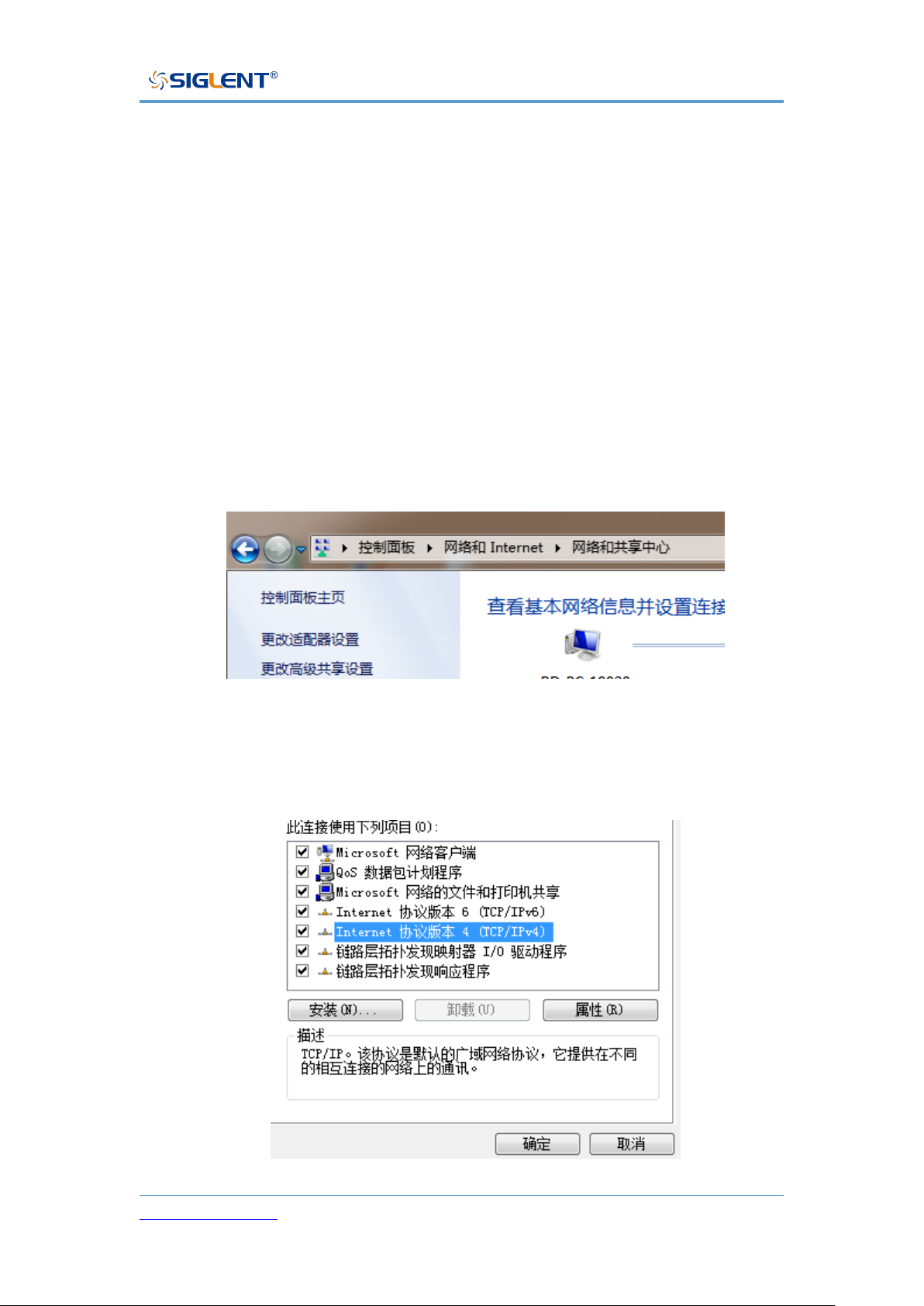
SPS5000X Series User Manual
WWW.SIGLENT.COM 86
Web Service
The SPS5000X can be remotely controlled through its embedded web control
interface.
The first connection method:
The PC computer is not connected to the network, and the SPS5000X and the
PC computer are directly connected through a network cable(cross-over cable).
First, set up the computer. The following takes the Windows 7 system as an
example:
1) Open the Network Sharing Center in the control panel and click Change
adapter settings
2) Right-click [Local Area Connection] and select [Properties], and double-click
Internet Protocol Version 4 (TCP/IPv4) in the pop-up window
Page 88
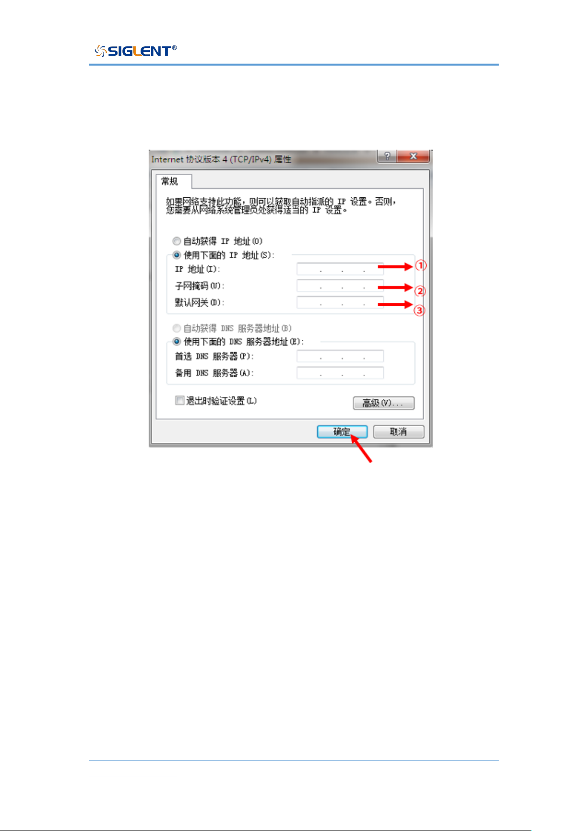
SPS5000X Series User Manual
WWW.SIGLENT.COM 87
3) Select [Use the following IP address] to set the IP address, subnet mask
and default gateway, and click OK after setting
4) The PC computer setting is completed.
① Set an IP address different from SPS
② Set the same subnet mask as SPS
③ Set the same gateway as SPS
Set the SPS power supply
Refer to the previous chapter [9.3.3] LAN settings, manually set SPS to be the
same as the PC computer subnet mask and default gateway, and set a different
IP address. At this point, the PC and SPS settings are completed, and the web
page can be opened for remote control.
The second connection method:
Page 89
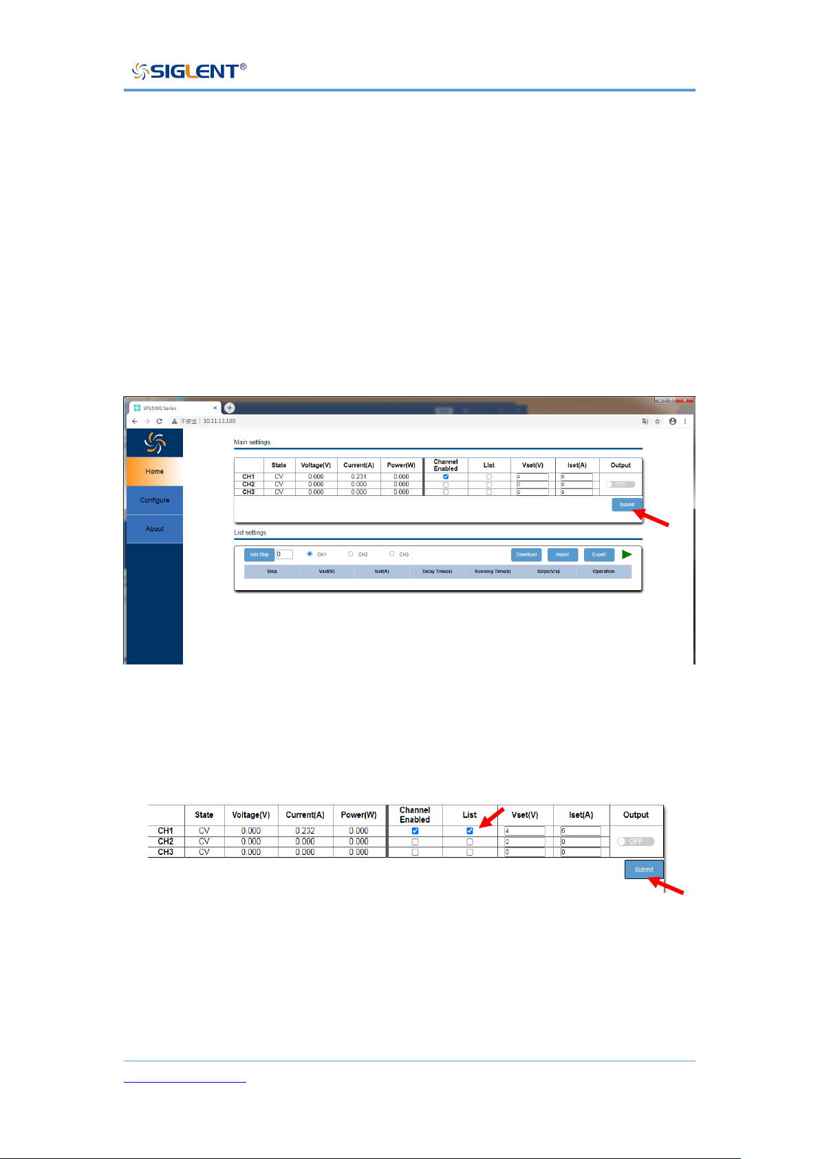
SPS5000X Series User Manual
WWW.SIGLENT.COM 88
SPS and PC are connected to the same network, SPS can automatically obtain
IP or manually change the IP address to be connected.
Web interface
After obtaining the IP address of the SPS5000X by any of the above methods,
open the Google browser on the PC and directly enter the IP address in the
input field to enter.
After configuring the voltage and current on the main interface, you need to click
the arrow at the arrow to submit, and the data will be sent to the power supply.
List operation method:
1) Set the channel mode to List mode. Select List, click Submit
2) Add the number of List steps, if it is a multi-channel model, select the
channel to be set
Page 90
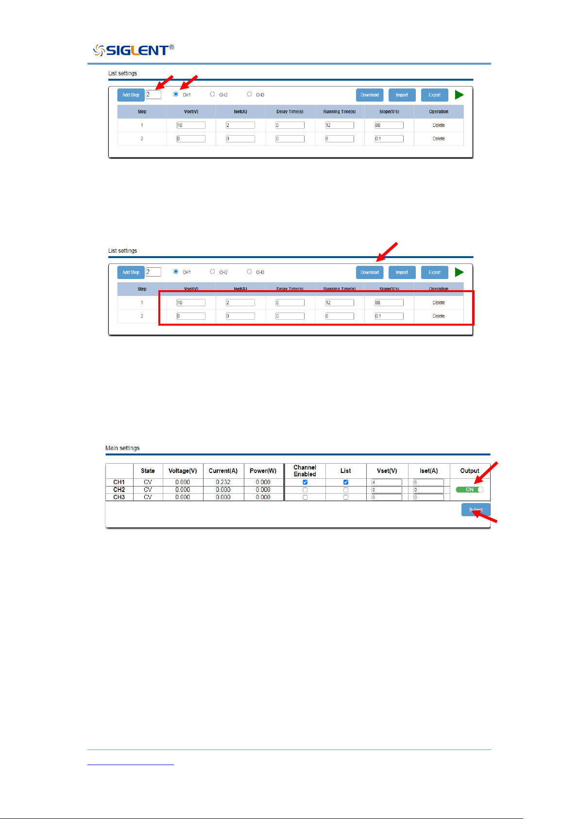
SPS5000X Series User Manual
WWW.SIGLENT.COM 89
3) Set the voltage and current parameters of each step, and click Download
after the output is completed to send the List data to the power supply
4) Turn on the Output switch of the channel and click Submit. After the setting
is successful, the power supply sets the output according to the number of
List steps, and the setting is completed.
Page 91
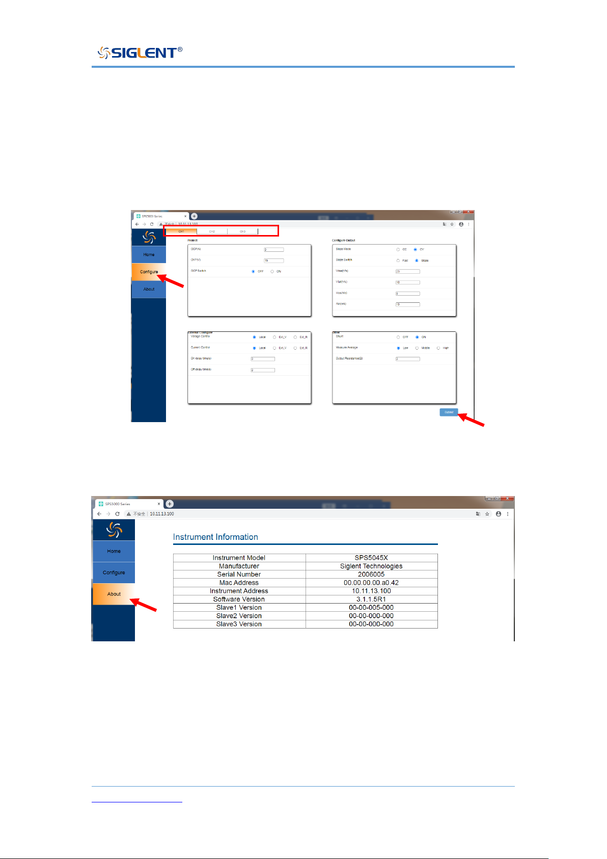
SPS5000X Series User Manual
WWW.SIGLENT.COM 90
Operating:
Click [Configure] in the left column to switch to the configuration interface
If it is a multi-channel model, select the channel to be configured at the top bar.
After performing function configuration on the Configure interface, you need to
click Submit at the arrow to send the data to the power supply.
Click [About] in the left column to view device information
Page 92

SPS5000X Series User Manual
WWW.SIGLENT.COM 91
Troubleshooting
The following lists the power supply in the use of the process of possible failures
and troubleshooting. When you encounter these faults, please follow the
corresponding steps to deal with them. If you can't handle them, please contact
siglent in time.
A. If the power on key is pressed, the power supply is still black, and there is
no display:
➢ Check whether the power connector is connected properly.
➢ After checking, please restart the power supply.
➢ If the power supply can not be started normally, please contact
SIGLENT.
B. No voltage output by output
➢ Check whether the voltage and current settings are correct
➢ Check whether the supply is in host mode, whether EXT on/off is in the
off state, Volt_ctrl and Curr_ctrl are in Local state, whether the output
resistance is set properly, whether the output delay time is too large,
and the slope mode setting is too small, which causes the output voltage
to rise slowly.
➢ Use the default setting to reset the voltage and current output after
restoring the factory settings.
➢ If the power supply still cannot be used normally, please contact
SIGLENT.
Page 93

SPS5000X Series User Manual
WWW.SIGLENT.COM 92
C. U disk cannot be recognized:
➢ Check whether the U disk device can work normally.
➢ Check whether the power USB HOST interface is working properly.
➢ Make sure that the flash-type U disk is used, and the power supply does
not support hard disk-type U disk devices.
➢ Re-plug the U disk, or restart the power and insert the U disk again.
➢ If you still cannot use the U disk normally, please contact SIGLENT.
Page 94

SPS5000X Series User Manual
WWW.SIGLENT.COM 93
Contact Us
Asia/Headquarters
SIGLENT TECHNOLOGIES CO., LTD.
Address: Blog No.4 & No.5, Antongda Industrial Zone, 3rd Liuxian Road,
Bao'an District, Shenzhen, 518101, China.
Tel:400-878-0807
E-mail:[email protected]
Website: Http://www.siglent.com
North America
SIGLENT TECHNOLOGIES North America
Address: 6557 Cochran Rd, Solon, OH 44039
Tel:440-398-5800
E-mail: [email protected]
Website: https://www.siglentna.com
Europe
SIGLENT Technologies Germany GmbH
Add: Staetzlinger Str. 70
86165 Augsburg, Germany
Tel: +49(0)-821-666 0 111 0
E-mail: [email protected]
Website: www.siglenteu.com
 Loading...