

Page 1
WWW.SIGLENT.COM
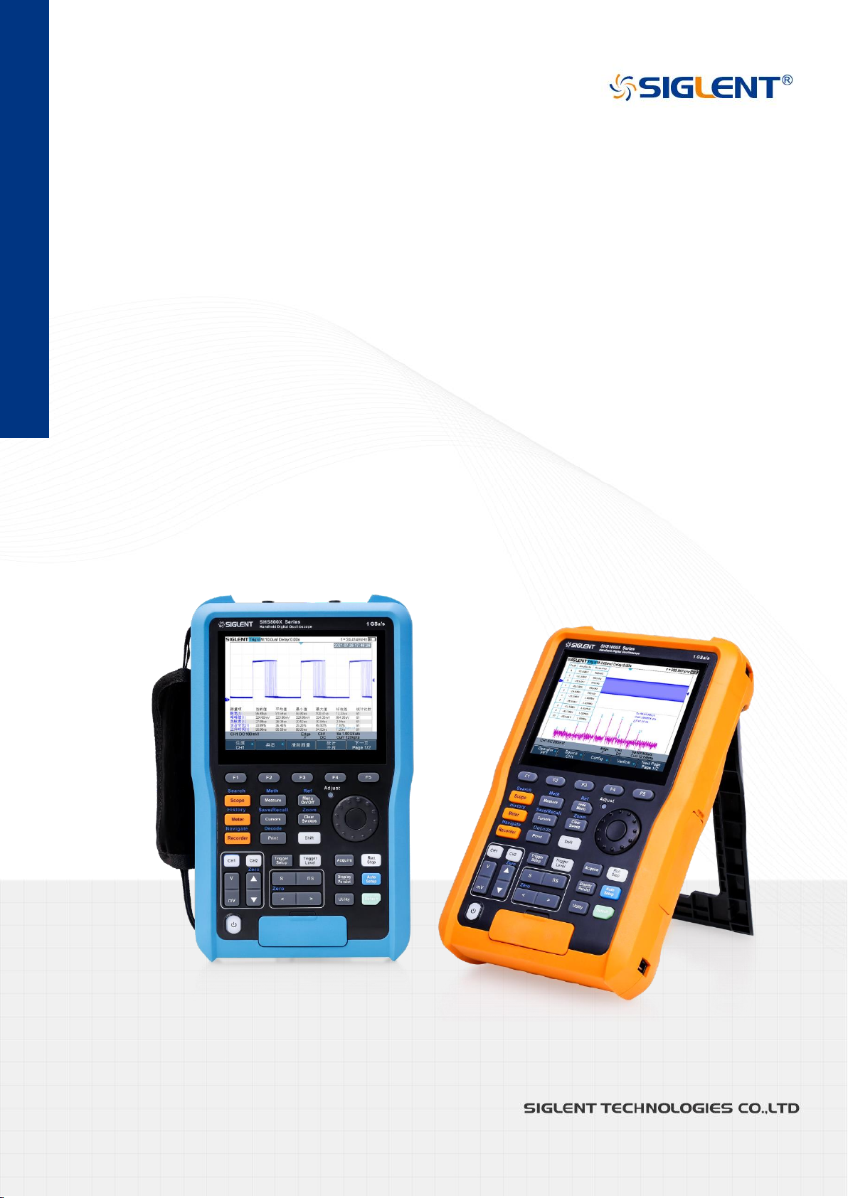
SHS800X
SHS1000X
Handheld Digital Oscilloscope
User Manual
EN01B
May,2022
1
Page 2

WWW.SIGLENT.COM
Copyright and Declaration
Copyright
SIGLENT TECHNOLOGIES CO., LTD. All Rights Reserved.
Trademark Information
SIGLENT is the registered trademark of SIGLENT TECHNOLOGIES CO., LTD.
Declaration
SIGLENT products are protected by patent law in and outside of P.R.C.
SIGLENT reserves the right to modify or change parts of or all the specifications or pricing
policies at company’s sole decision.
Information in this publication replaces all previously corresponding material.
Any way of copying, extracting or translating the contents of this manual is not allowed
without the permission of SIGLENT.
Product Certification
SIGLENT guarantees this product conforms to the national and industrial stands in China
and other international stands conformance certification is in progress.
Contact Us
If you have any problem or requirement when using our products, please contact SIGLENT
TECHNOLOGIES CO., LTD
Add:Blog No.4 & No.5, Antongda Industrial Zone, 3rd Liuxian Road, Bao’an District,
Shenzhen, 518101, China
Tel:400-878-0807
E-mail:[email protected]
http://www.siglent.com
II
Page 3
WWW.SIGLENT.COM
Introduction
Model
Analog Bandwidth
SHS820X
200 MHz bandwidth, 2-channel, 1 GSa/s Sample rate
SHS810X
100 MHz bandwidth, 2-channel, 1 GSa/s Sample rate
SHS1202X
200 MHz bandwidth, 2-channel, 1 GSa/s Sample rate
SHS1102X
100 MHz bandwidth, 2-channel, 1 GSa/s Sample rate
This user manual includes important safety and installation information related to the
SHS800X and SHS1000X handheld digital oscilloscopes, and includes simple tutorials for
basic operation of the oscilloscope.
The series includes the following models:
III
Page 4
WWW.SIGLENT.COM
General Safety Summary
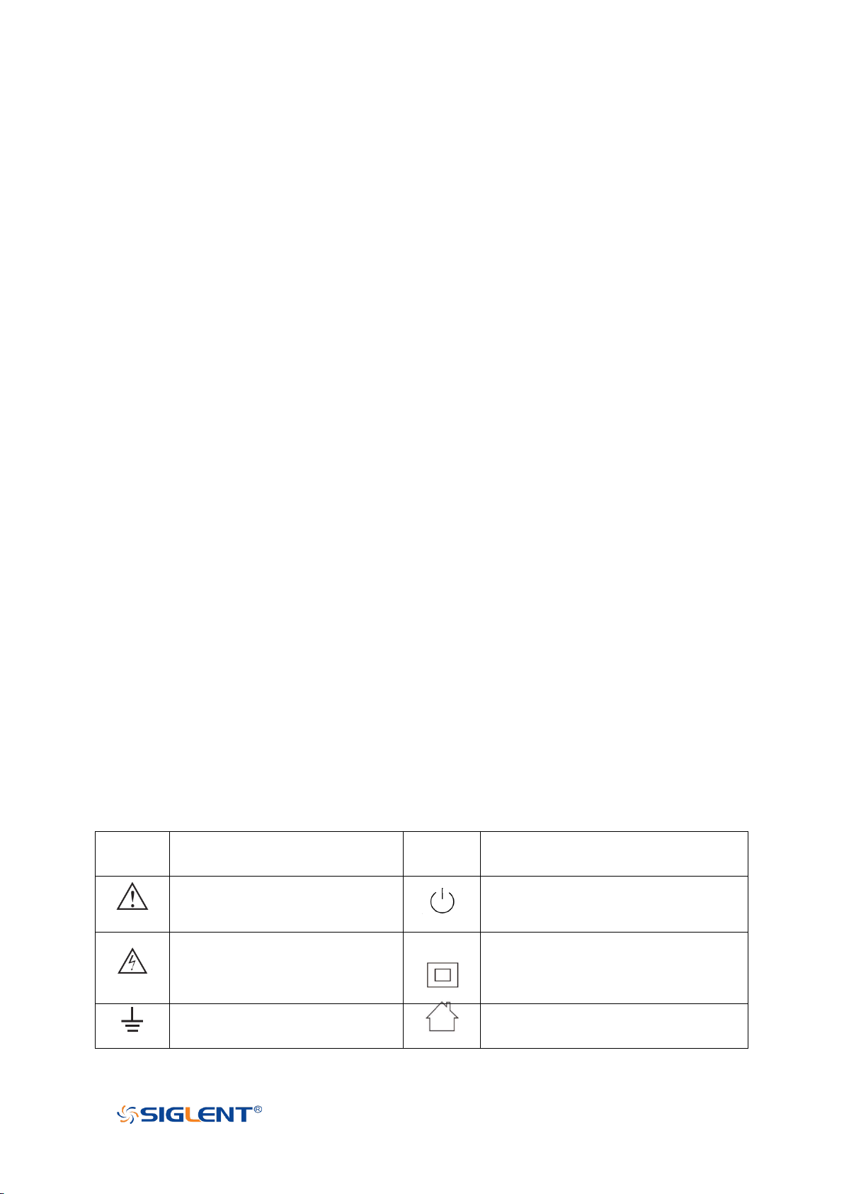
symbol
meaning
symbol
meaning
Warning
Power Switch
Hazardous Voltage
Equipment meeting double
insulation or reinforced insulation
EarthGround
Indoor use only
Carefully read the following safety precautions to avoid any personal injury or damage the
instrument and avoid any products connected to it. To avoid potential hazards, please use
the instrument as specified.
Protection is impaired if used in a manner not specified by the manufacturer.
Precautions for Operation
Before operating this product, special training is required to ensure that the user is
physically, mentally and emotionally healthy and able to use the oscilloscope, otherwise it
may cause personal injury or material damage. Employers、operators are responsible for
selecting suitable personnel to operate this product.
Before moving or transporting this product. Please read and observe the "Safety
Transportation Matters" chapter.
As with all industrial products, the use of substances that cause allergic reactions such as
nickel cannot generally be ruled out. If you experience an allergic reaction while using this
product, please consult a doctor in time to determine the cause.
Before you perform mechanical or heat treatment or disassemble the oscilloscope, please
be sure to read and pay special attention to the "Waste Disposal/Environmental
Protection" chapter.
In the event of a fire, this product may release harmful substances (gas, liquids, etc.),
causing health problems. Therefore, appropriate measures must be taken, for example,
protective masks and protective clothing must be worn.
Safety Terms and Symbols
The meaning of symbols
IV
Page 5
WWW.SIGLENT.COM
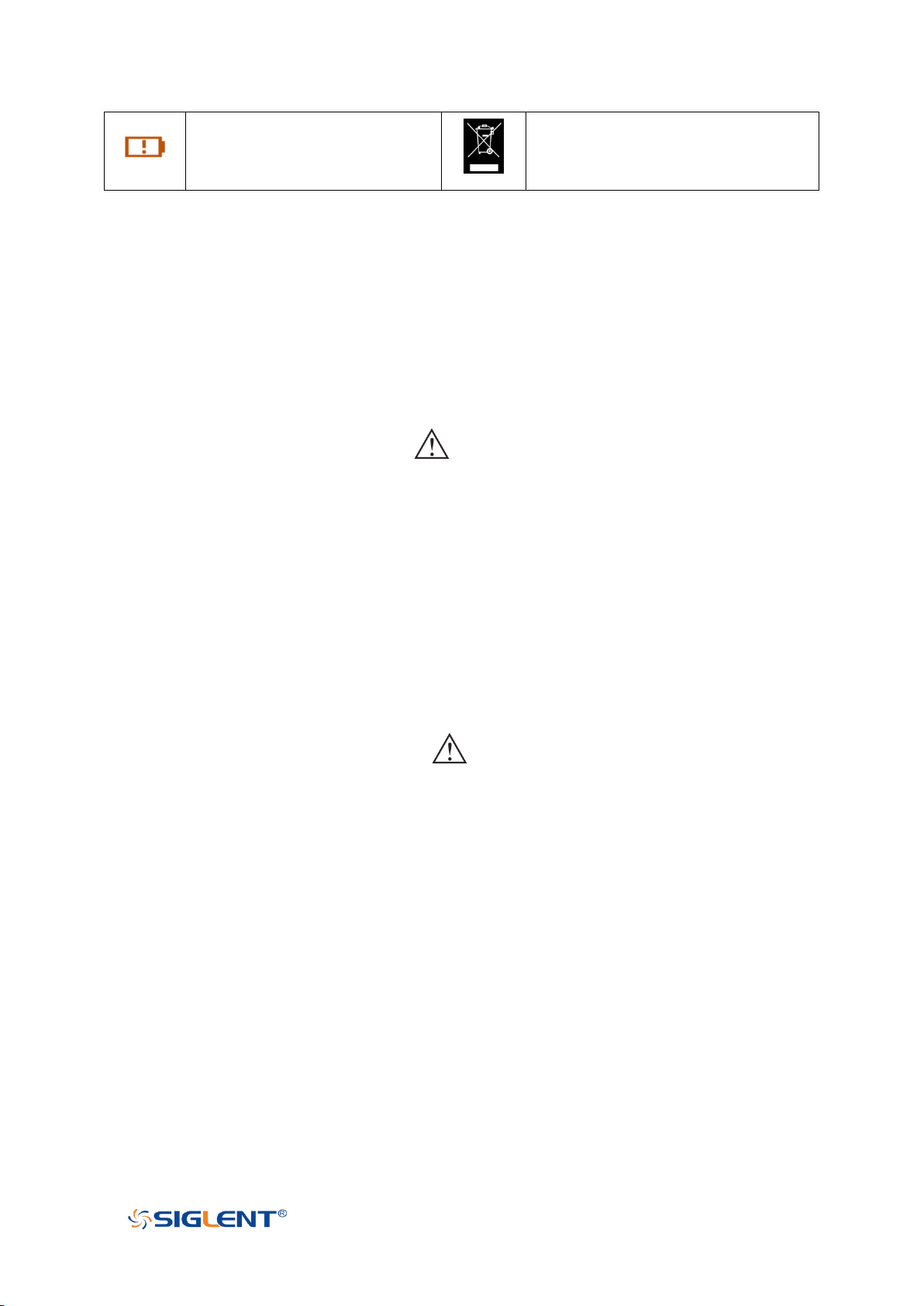
Lithium battery failure
EU label for separately recycled
electrical and electronic equipment
Cue and its meaning
DANGER: Indicates direct injury or hazards that may happen.
WARNING: Indicates potential injury or hazards that may happen.
CAUTION: Indicates potential damage to the instrument or other property that may
happen.
It must be consulted in all cases where is marked, in order to find out the nature of the
potential HAZARDS and any actions which have to be taken to avoid them.
Cue et sa signification
DANGER : Indique des blessures directes ou des dangers qui peuvent survenir.
WARNING : indique des blessures ou des dangers potentiels pouvant survenir.
CAUTION: indique des dommages potentiels à l'instrument ou à d'autres biens pouvant
survenir.
Il doit être consulté dans tous les cas où est marqué, afin de connaître la nature des
DANGERS potentiels et les actions à entreprendre pour les éviter.
Safety Operation Matters
The product can only be operated under the safe conditions and positions specified by the
manufacturer. Do not obstruct the ventilation of the oscilloscope during use. Failure to
comply with the manufacturer's specifications may result in electric shock, fire, serious
personal injury, or even death. Applicable local safety regulations and accident
prevention rules must be observed in all applications.
When powered by a power adapter, it can only be used indoors.
Do not place the product on surface, vehicle, cabinet or tables that for reasons of weight
or stability are unsuitable for this purpose. When installing the product and fastening it to
the article or structures, always follow the manufacturer's installation instructions. If the
V
Page 6

WWW.SIGLENT.COM
installation is not carried out in accordance with the requirements of the document, it may
cause personal injury or even death.
Do not use this product in or near a heat source, and the ambient temperature cannot
exceed the maximum temperature in the document or datasheet
Safety of Electricity
If you ignore the electrical safety methods, electric shock, fire and/or serious personal
injury or death may occur.
Only use the power adapter and battery specified by the manufacturer to power the
oscilloscope, and the power adapter can only work within its rated input voltage range.
Only the probe specified by the manufacturer can be used for testing. The use of
non-manufacturer probes for testing may result in electric shock accidents.
The user is not allowed to damage the insulation protection layer of the oscilloscope and
accessories. Doing so may cause electric shock. If an extension cord or terminal block is
used for power supply, it must be checked regularly to ensure safe use.
Before use, please check whether the power cord and probe are damaged. If the power
cord and probe are damaged, please do not continue to use the product.
Do not insert the AC plug of the power adapter into a dusty or dirty socket. Please make
sure that the plug is firmly inserted into the socket, otherwise it may cause fire and/or
injury due to sparks.
Do not overload any sockets, extension cords or connectors. Doing so may cause fire or
electric shock.
When the measured voltage Vrms exceeds 30V, you should take appropriate
measurement methods to avoid any danger.
Unless expressly permitted, do not remove the cover or any part of the shell while the
product is in operation. Doing so will expose circuits and components, reduce the
overvoltage level of the measurement, and may cause personal injury, fire, or damage to
the oscilloscope.
Anything that is not designed to be placed on the external interface of this product should
not be placed on the external interface, otherwise it will cause an internal short circuit
and/or electric shock, fire or injury to the oscilloscope.
Do not place this product in an environment exceeding IP51, otherwise the oscilloscope
will be damaged.
This product must be used in a dry environment, otherwise it may cause electric shock.
It is forbidden to use this product when condensation has formed or may form inside or on
the surface of this product. For example, when the oscilloscope moves from a cold
environment to a warm environment, the penetration of water increases the risk of electric
shock.
VI
Page 7

WWW.SIGLENT.COM
Safety Transportation Matters
SIGLENT Technology provides handbags for the oscilloscope. For short-distance
transportation under supervision, please make sure that the oscilloscope is turned off
before putting it in the handbag. For long-distance transportation under unsupervised,
please take out the battery and put it in your handbag.
In order to facilitate the user to hold, SIGLENT Technology has installed a fabric handle on
the oscilloscope. This handle cannot be used as a focus point to be fixed on transportation
equipment, such as cranes, forklifts, trucks, etc. It is the user's responsibility to fasten the
product firmly to the transportation or lifting tool.
If you use this product in a vehicle, the driver is responsible for driving the vehicle safely
and correctly. The manufacturer is not responsible for any accidents or collisions. Do not
use this product in a moving vehicle to avoid distracting the driver. Use this product
appropriately in the vehicle to prevent injury or other damage in the event of an accident.
Battery Usage
This product contains a rechargeable lithium battery pack. If misused, there is a risk of
explosion, fire and / or serious personal injury, and even death in some cases.
The battery cannot be disassembled or crushed.
The battery or battery pack cannot be exposed to high temperature or fire, and it must be
stored in direct sunlight. Keep the battery clean and dry. Use a dry, clean cloth to clean
contaminated connectors.
The battery or battery pack cannot be short-circuited. Batteries or battery packs should not
be stored in an environment that can easily cause a short circuit, such as boxes and
drawers containing metal debris. The battery pack cannot be taken out of its original
packaging before use.
Batteries and battery packs should not be exposed to any mechanical shock that exceeds
the allowable level.
If the battery leaks, do not let the liquid contact the skin or eyes. If contact occurs, wash
the contact area with plenty of water and seek medical assistance.
The power adapter specified by SIGLENT Technology must be used for charging, otherwise
it may cause a fire or cause personal injury or death.
It must be charged in a well-ventilated room. During the charging process, the
oscilloscope should not be covered by objects (such as blankets, towels, clothes), which
will affect the heat dissipation effect and cause a serious fire.
Improper battery replacement may cause an explosion. For the reliability and safety of the
oscilloscope, the battery model specified by SIGLENT Technology must be replaced.
Used batteries and battery packs must be recycled and separated from residual waste.
Batteries contain hazardous waste, and local regulations on waste disposal and recycling
must be followed.
II
Page 8

WWW.SIGLENT.COM
Waste Disposal
The used batteries in the product must not be disposed of together with unsorted
municipal waste, they must be collected separately and placed in designated recycling
points.
If the product and its components are mechanically and/or thermally processed in a way
beyond the intended use, hazardous substances may be released. Therefore, this product
can only be disassembled by professional personnel. Improper disassembly may
endanger your health. The local waste disposal regulations must be followed.
Safety Compliance
This section lists the safety standards with which the product complies.
U.S. nationally recognized testing laboratory listing
UL 61010-1:2012/R:2018-11. Safety Requirements for Electrical Equipment for
Measurement, Control, and Laboratory Use – Part 1: General Requirements.
UL 61010-2-030:2018. Safety Requirements for Electrical Equipment for Measurement,
Control, and Laboratory Use – Part2-030: Particular requirements for testing and
measuring circuits.
UL 61010-2-033:2020. Safety Requirements for Electrical Equipment for Measurement,
Control and Laboratory Use – Part 2-033: Particular Requirements for Hand-Held
Multimeters for Domestic and Professional Use, Capable of Measuring Mains Voltage.
Canadian certification
CAN/CSA-C22.2 No. 61010-1:2012/A1:2018-11. Safety Requirements for Electrical
Equipment for Measurement, Control, and Laboratory Use – Part 1: General
Requirements.
CAN/CSA-C22.2 No. 61010-2-030:2018. Safety Requirements for Electrical Equipment
for Measurement, Control, and Laboratory Use – Part 2-030: Particular requirements
for testing and measuring circuits.
CSA C22.2 No. 61010-2-033-2020. Safety Requirements For Electrical Equipment For
Measurement, Control And Laboratory Use — Part 2-033: Particular Requirements For
Hand-Held Multimeters For Domestic And Professional Use, Capable Of Measuring
Mains Voltage
General Care and Cleaning
Care
Do not store or leave the instrument in direct sunshine for extended periods of time.
III
Page 9
WWW.SIGLENT.COM
To avoid damages to the instrument or probes, please do not expose them to fog, liquid,
or solvents.
Cleaning
Please perform the following steps to clean the instrument and probes regularly in
accordance with its operating conditions.
Disconnect the instrument from all power sources and then clean with a soft wet cloth.
Clean the loose dust on the outside of the instrument and probe with a soft cloth. When
cleaning the LCD, take care to avoid scratching it.
To avoid damage to the surface of the instrument and probe, please do not use any
corrosive liquid or chemical cleansers.
Make sure that the instrument is completely dry before restarting it to avoid potential short
circuits or personal injury.
Measurement Category
WARNING
Make sure that no measurement overvoltage reach the product, or else the
operator might expose to danger of electric shock.
Assurez-vous qu'aucune surtension de mesure n'atteigne le produit, sinon
l'opérateur pourrait s'exposer à un risque de choc électrique.
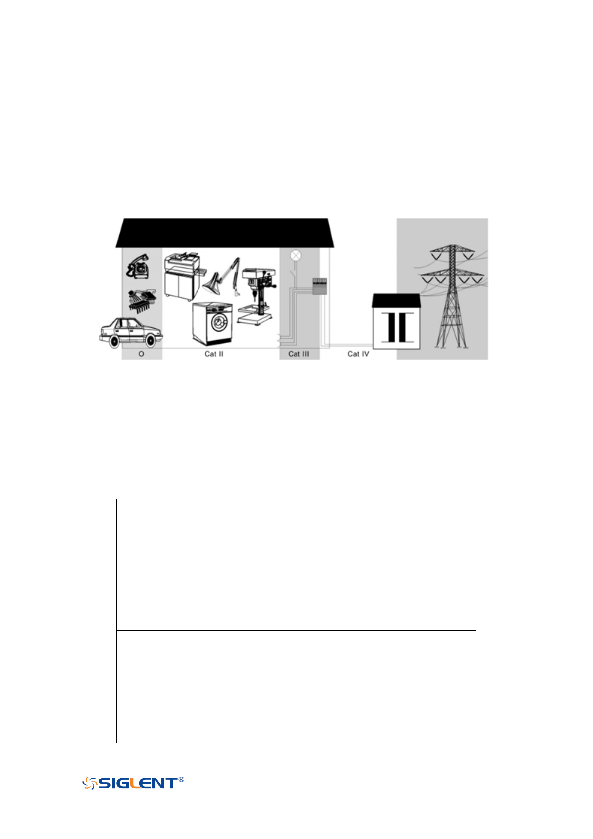
IEC61010-2-030 defines the measurement category to rate the ability of measuring
instruments to withstand short-term transient overvoltage outside of the working voltage.
This product and its accessories can only be used in the environment of the nominal
measurement category.
0- An instrument with no rated measurement category is used to measure circuits that
are not directly connected to the mains, such as a circuit board powered by a battery
or a secondary circuit with special protection. This measurement category is also
called CATⅠ.
CAT II:
For measurements installed in buildings, such as junction boxes, circuit breakers,
IV
Page 10
WWW.SIGLENT.COM
distribution boards and equipment permanently connected to fixed installations.
SHS800X
Max Input Voltage
Scope(BNC input)
CAT II 300Vrms Between BNC Signal and
Protecting Earth.
CAT II 30Vrms Between BNC GND and
Protecting Earth.
CAT II 300Vrms Between BNC Signal and
BNC GND.
Scope(Probe input)
CAT II 300Vrms Between Signal and
Protecting Earth.
CAT II 30Vrms Between Probe GND and
Protecting Earth.
CAT II 300Vrms Between Probe Signal
and Probe GND.
CAT III:
Used for measurements installed in buildings, such as junction boxes, circuit breakers,
distribution boards and equipment that are permanently connected to fixed
installations.
CAT IV:
It is used for measuring at the source of low-voltage devices, such as electricity meters
and primary overcurrent protection devices.
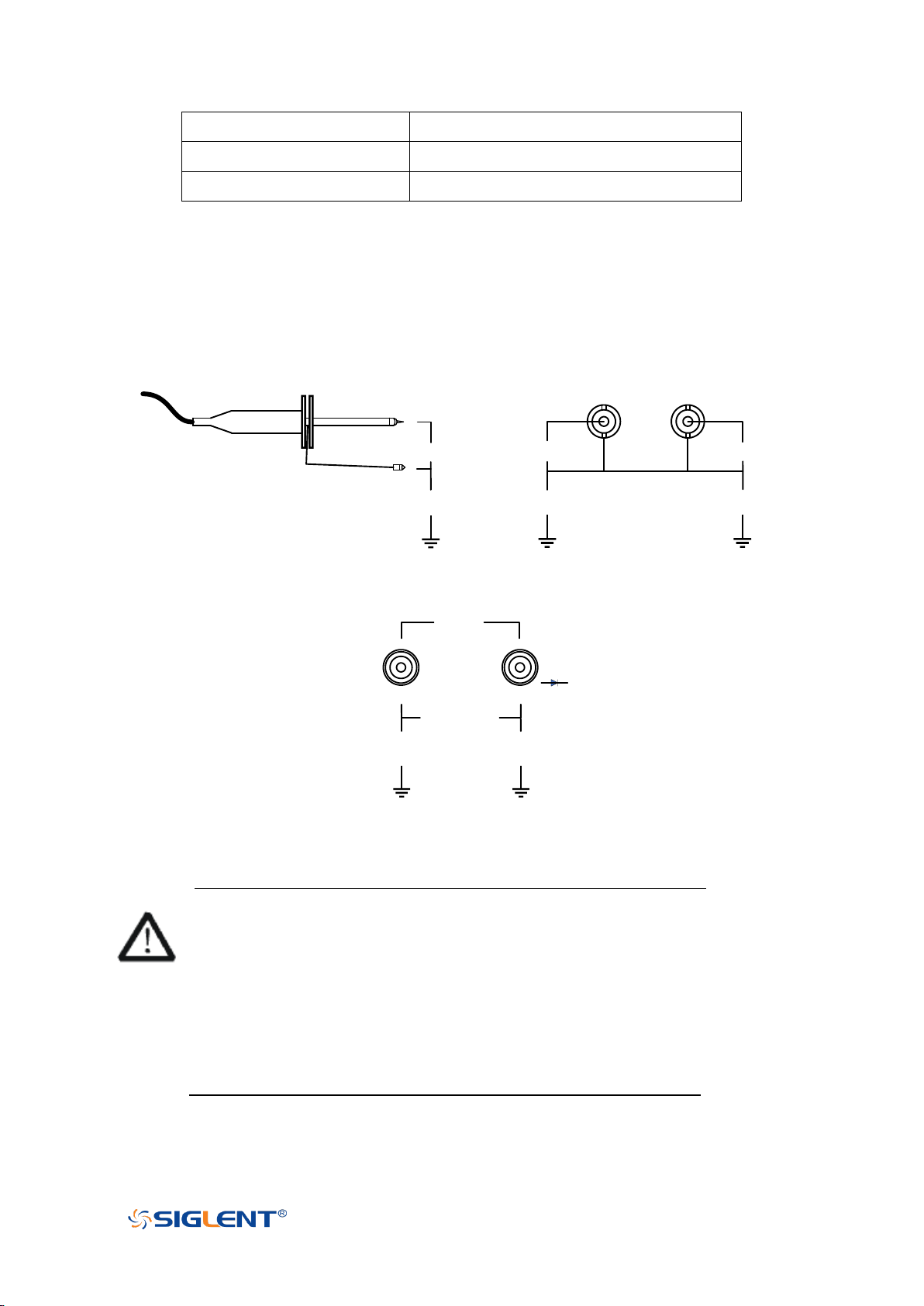
SHS800X Measurement Category
SHS800X can working under the measurement category listed in the table below, The
applicable measurement category of a combination of a probe assembly and an
accessory is the lower of the measurement category.
V
Page 11
WWW.SIGLENT.COM
Multimeter
CAT III 300Vrms, CATII 600Vrms.
SCD10A
[1]
CAT III 60Vrms.
SCD600MA
[1]
CAT III 60Vrms.
INPUT A
INPUT B
System GND
Protecting GND
CAT II 300V
CAT II 30V
CAT II 300V
CAT II 30V
Probe Input BNC Input
COM
V
Ω
Meter
Input
CAT III 300V
CAT II 600V
CAT III 300V
CAT II 600V
CAT III 300V
CAT II 600V
Protecting GND
Note: SCD10A is a 10A current adapter for the meter using to measure a current up to 10A,
SCD600MA is a 600mA current adapter for the meter using to measure a current up to
600mA. Refer to the DCI/ACI chapter for more information.
Measurement Category for SHS800X Scope
Measurement Category for SHS800X Multimeter
WARNING
Electrical Shock Hazard!
The reference ground of SHS800X CH1 and CH2 are connected together,
connected one of them to the voltage higher than 30Vrms and touch the other
one may results in personal injury.
Risque de choc électrique !
Les masses de référence du SHS800X CH1 et CH2 sont connectées ensemble,
connectées l'une d'elles à une tension supérieure à 30 Vrms et toucher l'autre
peut entraîner des blessures.
VI
Page 12
WWW.SIGLENT.COM
SHS1000X
Max Input Voltage
Scope(BNC input)
CAT III 600Vrms/CAT II 1000Vrms Between
BNC Signal and Protecting Earth.
CAT III 600Vrms/CAT II 1000Vrms Between
BNC GND and Protecting Earth.
CAT III 300Vrms Between BNC Signal and
BNC GND.
Scope(Probe input)
CAT III 600Vrms, CAT II 1000Vrms.
Multimeter
CAT III 600Vrms, CAT II 1000Vrms.
SCD10A
[1]
CAT III 60Vrms.
SCD600MA
[1]
CAT III 60Vrms.
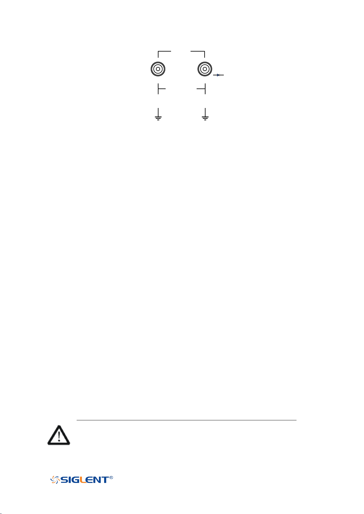
INPUT A INPUT B
CAT III 600V
/CAT II 1000V
CAT III 600V
/CAT II 1000V
GND A
GND B
Protecting GND
Probe Input BNC Input
CAT III 300V
CAT III 600V
/CAT II 1000V
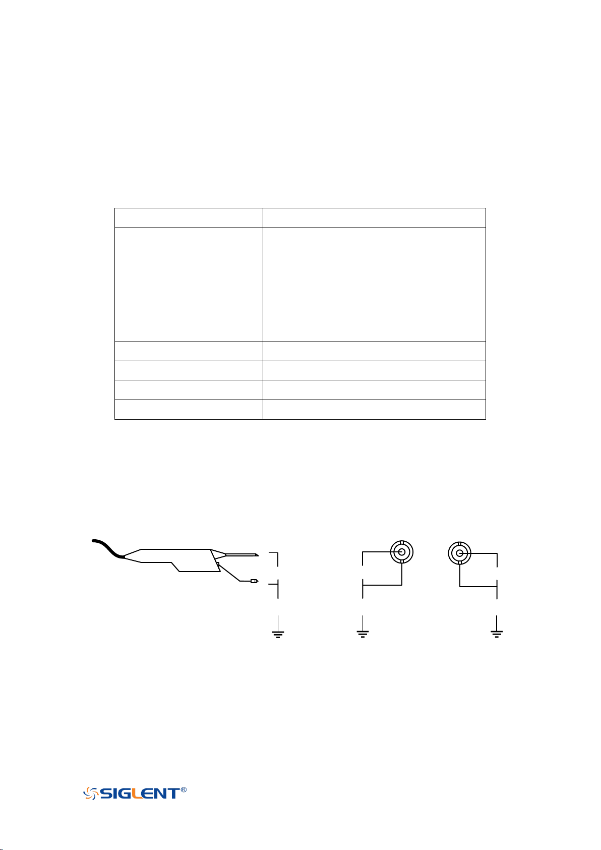
SHS1000X Measurement Category
SHS1000X can working under the measurement category listed in the table below The
applicable measurement category of a combination of a probe assembly and an
accessory is the lower of the measurement category.
Note: SCD10A is a 10A current adapter for the meter using to measure a current up to 10A,
SCD600MA is a 600mA current adapter for the meter using to measure a current up to
600mA. Refer to the DCI/ACI chapter for more information.
Measurement Category for SHS1000X Scope
VII
Page 13
WWW.SIGLENT.COM
COM
V
Ω
Meter
Input
CAT III 600V
CAT II 1000V
CAT III 600V
CAT II 1000V
CAT III 600V
CAT II 1000V
Protecting GND
Measurement Category for SHS1000X Multimeter
Working Environment
General requirement
Environment
This product is intended for indoor use and should be operated in a clean, dry
environment.
It can be stored in an environment with a waterproof/dustproof rating better than IP51.
Temperature
Operating: 0℃ to +40℃
Non-operation:-20℃ to +60℃
Note: Direct sunlight, radiators, and other heat sources should be taken into account when
assessing the ambient temperature.
Humidity
Operating: 85% RH, 40 ℃, 24 hours
Non-operating: 85% RH, 65 ℃, 24 hours
Altitude
Operating: less than 2 Km
Non-operation: less than 5 Km
Installation (overvoltage) Category
This product is powered by mains conforming to installation (overvoltage) category II.
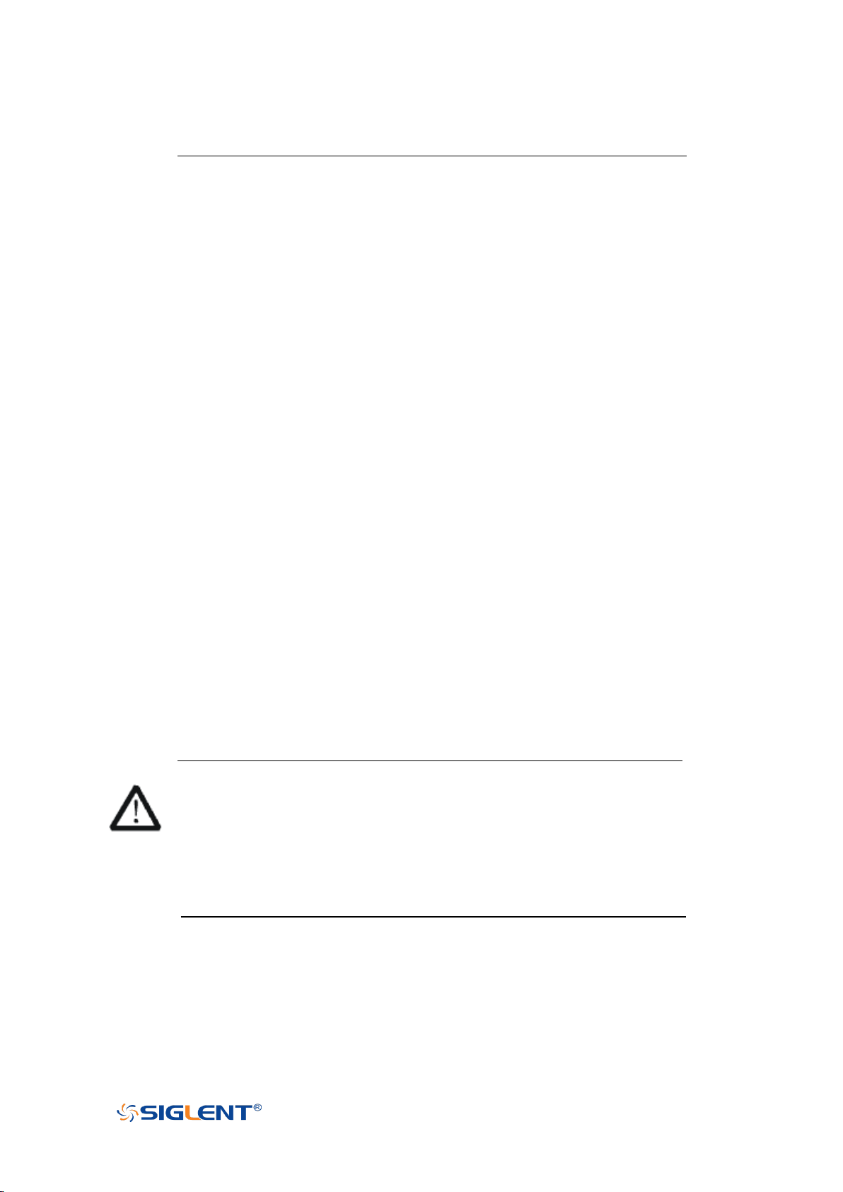
WARNING
Make sure that no overvoltage (such as that caused by thunderbolt) can reach
the product, or else the operator might expose to danger of electric shock.
Assurez-vous qu'aucune surtension (comme celle causée par la foudre) ne
VIII
Page 14
WWW.SIGLENT.COM
peut atteindre le produit, sinon l'opérateur pourrait s'exposer à un risque de
choc électrique.
Installation (overvoltage) Category Definitions
Installation (overvoltage) category I refers to signal level which is applicable to equipment
measurement terminals connected to the source circuit. In these terminals, precautions
are done to limit the transient voltage to the corresponding low level.
Installation (overvoltage) category II refers to the local power distribution level which is
applicable to equipment connected to the AC line (AC power).
Degree of Pollution
The oscilloscopes may be operated in environments of Pollution Degree II.
Note: Degree of Pollution II refers to a working environment which is dry and
non-conductive pollution occurs. Occasional temporary conductivity caused by
condensation is expected.
IP Rating
IP51 (as defined in IEC 60529).
Ventilation Requirement
Please make sure that the air intake and exhaust areas are free from obstructions and
have free air. When using the oscilloscope in a bench-top or rack setting, provide at least
10 cm clearance beside, above and behind the instrument for adequate ventilation.
WARNING
Inadequate ventilation may cause temperature increase which would damage
the instrument. So please keep the instrument well ventilated during operation.
Une ventilation inadéquate peut entraîner une augmentation de la
température qui endommagerait l'instrument. Veuillez donc garder
l'instrument bien ventilé pendant le fonctionnement.
IX
Page 15
WWW.SIGLENT.COM
AC Power Requirement
Voltage Range:
90 - 264 Vrms
Frequency Range:
47 - 63 Hz
The power adapter operates with a single-phase, 100 to 240 Vrms (+/-10%) AC power at
50/60 Hz (+/-5%).
No manual voltage selection is required because the instrument automatically adapts to
line voltage.
Depending on the type and number of options and accessories (probes, PC port plug-in,
charging etc.), When powered by adapter, the scope can consume up to 35 W of power.
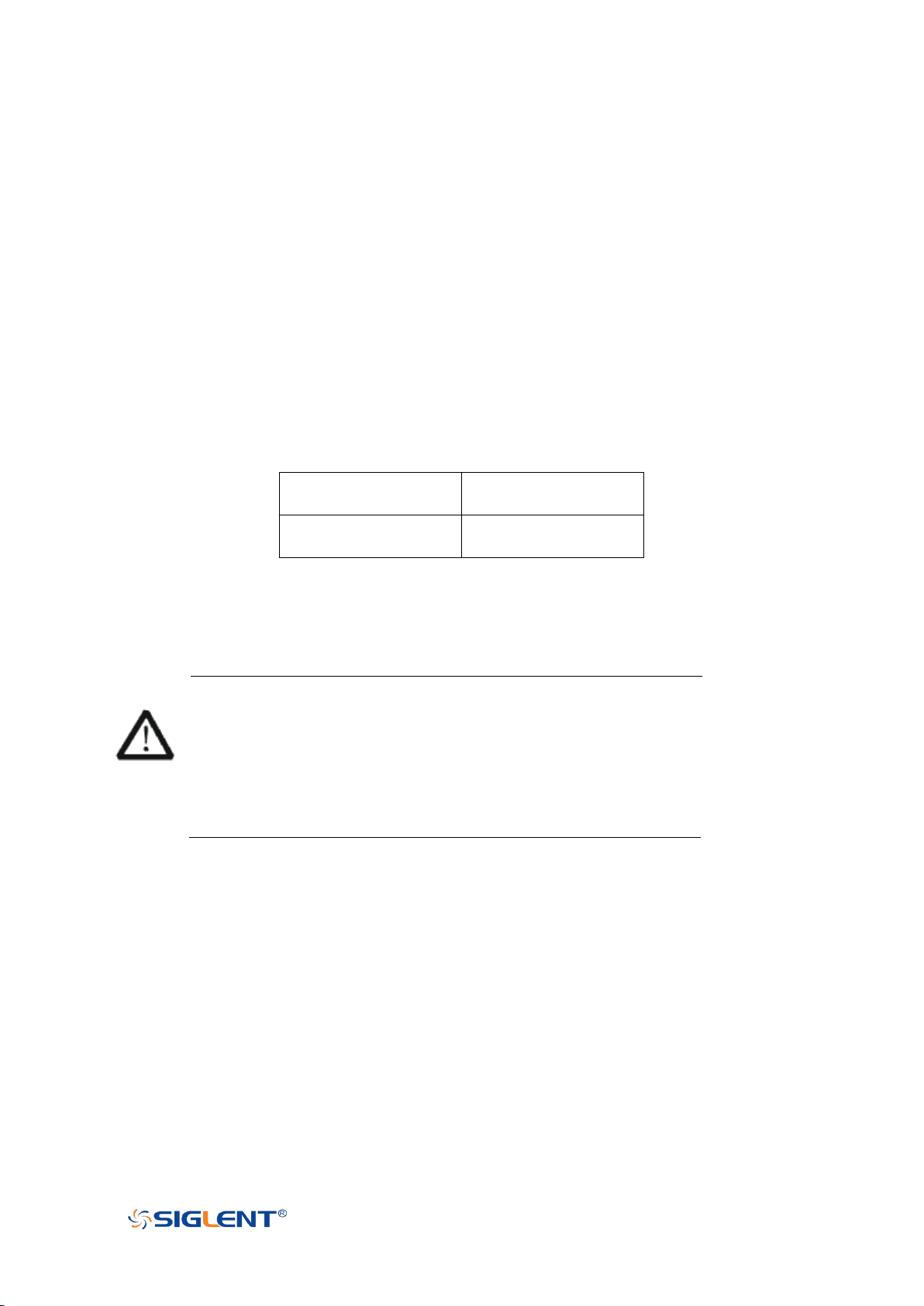
Note: The power adapter automatically adapts to the AC line input within the following
ranges:
Please use the power cord and adapter provided by the manufacturer. Use of other
non-designated products may cause personal injury.
WARNING
Electrical Shock Hazard!
Use of an adapter or power supply not specified by the manufacturer may
cause personal injury.
Risque de choc électrique !
L'utilisation d'un adaptateur ou d'un bloc d'alimentation non spécifié par le
fabricant peut entraîner des blessures.
To make the oscilloscope completely power off, unplug the instrument power cord from
the AC socket and remove the battery from the scope.
The battery should be removed from the scope when it is not to be used for an extended
period of time.
I
Page 16

WWW.SIGLENT.COM
Maintenance and Services
Only authorized and specially trained personnel can open the oscilloscope. When
performing maintenance operations on the oscilloscope, you must remove the power
adapter and make sure that the oscilloscope is turned off, otherwise it may cause an
internal short circuit of the oscilloscope.
Adjustment, replacement of parts, maintenance and repair can only be performed by
operators authorized by SIGLENT Technology. Safety-related parts can only be replaced
with original parts. Safety tests must be carried out after replacing parts.
II
Page 17

WWW.SIGLENT.COM
Document Overview
Quick Start
Provide information about preparations
before using the instrument and a brief
introduction of the instrument.
Vertical System
Introduce the functions of the vertical
system of the oscilloscope.
Horizontal System
Introduce the functions of the horizontal
system of the oscilloscope.
Acquisition System
Introduce the functions of the sample
system of the oscilloscope.
Trigger
Introduce the trigger mode, trigger
coupling, trigger hold off, external trigger
and various trigger types of the
oscilloscope.
Serial Trigger and Decode
Introduce the functions of the serial trigger
and decode.
Reference Waveform
Introduce how to save and display REF
waveform.
Math
Introduce the math operation function of the
oscilloscope.
Cursors
Introduce how to use cursors to make
measurements.
Measure
Introduce how to measure the waveform
parameters.
Display
Introduce how to set the display of the
oscilloscope.
Save and Recall
Introduce how to save and recall the
measurement result and the setting of the
oscilloscope.
System Setting
Introduce how to set the system setup.
Search
Introduce the oscilloscope search function
Navigate
Introduce how to use the waveform
navigation function of the oscilloscope
History
Introduce how to use and set historical
waveform functions.
Meter
Introduce how to use meter function.
Recorder
Introduce how to use recorder function.
This manual introduces how to use the digital oscilloscope in details.
XXIV
Page 18

WWW.SIGLENT.COM
Table of Content
Copyright and Declaration ............................................................................................... II
Introduction ...................................................................................................................... III
General Safety Summary ............................................................................................... IV
Precautions for Operation ....................................................................................... IV
Safety Terms and Symbols...................................................................................... IV
Safety Operation Matters ......................................................................................... V
Safety of Electricity................................................................................................... VI
Safety Transportation Matters .................................................................................. II
Battery Usage ............................................................................................................. II
Waste Disposal .......................................................................................................... III
Safety Compliance .................................................................................................... III
General Care and Cleaning ............................................................................................. III
Measurement Category .................................................................................................. IV
SHS800X Measurement Category ........................................................................... V
SHS1000X Measurement Category ....................................................................... VII
Working Environment ................................................................................................... VIII
General requirement ............................................................................................. VIII
Ventilation Requirement ......................................................................................... IX
AC Power Requirement .............................................................................................. I
Maintenance and Services ............................................................................................... II
Document Overview ................................................................................................... XXIV
Quick Start .......................................................................................................................... 2
Appearance and Dimensions ................................................................................... 3
Prepare for Using ....................................................................................................... 4
Adjust the Supporting Leg ................................................................................. 4
Battery Installation ............................................................................................. 4
Connect the Power Supply ................................................................................. 5
Power-on Inspection .......................................................................................... 6
Connect the Probe .............................................................................................. 6
Function Inspection ............................................................................................ 6
Probe Compensation .......................................................................................... 8
Multimeter Meter Pen ......................................................................................... 8
Front Panel Overview ................................................................................................ 9
Side Panel Overview ................................................................................................ 10
Rear Panel Overview ............................................................................................... 11
Front Panel Function Overview .............................................................................. 12
Horizontal .......................................................................................................... 12
Vertical ................................................................................................................. 13
Trigger ................................................................................................................ 14
Run Control ........................................................................................................ 15
Universal Knob .................................................................................................. 16
Other Buttons .................................................................................................... 17
XXIX
Page 19

WWW.SIGLENT.COM
Help ............................................................................................................................ 19
User Interface ........................................................................................................... 20
Vertical System ................................................................................................................ 22
Enable the Channel .................................................................................................. 23
Adjust Scale .............................................................................................................. 24
Vertical Position ....................................................................................................... 25
Coupling .................................................................................................................... 25
Bandwidth Limit ....................................................................................................... 26
Probe .......................................................................................................................... 26
Unit ............................................................................................................................. 27
Deskew ...................................................................................................................... 27
Invert .......................................................................................................................... 27
Trace Visible/Hidden ............................................................................................... 28
Horizontal System ........................................................................................................... 29
Horizontal Scale ....................................................................................................... 30
Horizontal Delay....................................................................................................... 31
Roll Mode .................................................................................................................. 32
Zoom Mode ............................................................................................................... 33
Acquisition System .......................................................................................................... 35
Overview ................................................................................................................... 36
Sampling Theory ............................................................................................... 36
Sample Rate....................................................................................................... 36
Bandwidth and Sample Rate........................................................................... 37
Memory Depth .......................................................................................................... 39
Sampling Mode ........................................................................................................ 40
Interpolation Method ............................................................................................... 41
Acquisition Mode ...................................................................................................... 44
Normal ................................................................................................................ 44
Peak Detect ........................................................................................................ 45
Average .............................................................................................................. 46
ERES .................................................................................................................... 48
Horizontal Format .................................................................................................... 49
Sequence Mode ........................................................................................................ 51
Trigger............................................................................................................................... 53
Trigger Source .......................................................................................................... 55
Trigger Mode ............................................................................................................. 56
Trigger Level ............................................................................................................. 58
Trigger Coupling ....................................................................................................... 59
Trigger Holdoff ......................................................................................................... 60
Noise Rejection ......................................................................................................... 61
Trigger Type .............................................................................................................. 63
Edge Trigger ...................................................................................................... 64
Slope Trigger ..................................................................................................... 66
Pulse Trigger ...................................................................................................... 68
XXX
Page 20

WWW.SIGLENT.COM
Video Trigger ..................................................................................................... 70
Window Trigger ................................................................................................. 74
Interval Trigger.................................................................................................. 77
Dropout Trigger ................................................................................................. 79
Runt Trigger ....................................................................................................... 82
Pattern Trigger .................................................................................................. 84
Serial Trigger and Decode ............................................................................................. 86
I2C Trigger and Serial Decode ................................................................................ 87
Setup for I2C Signals ......................................................................................... 87
I2C Trigger .......................................................................................................... 88
I2C Serial Decode .............................................................................................. 92
SPI Trigger and Serial Decode ................................................................................ 94
Setup for SPI Signals......................................................................................... 94
SPI Trigger .......................................................................................................... 98
SPI Serial Decode .............................................................................................. 99
UART Trigger and Serial Decode .......................................................................... 101
Setup for UART Signals .................................................................................. 101
UART Trigger .................................................................................................... 103
UART Serial Decode ........................................................................................ 104
CAN Trigger and Serial Decode ............................................................................ 106
Setup for CAN Signals .................................................................................... 106
CAN Trigger ...................................................................................................... 107
CAN Serial Decode .......................................................................................... 108
LIN Trigger and Serial Decode .............................................................................. 110
Setup for LIN Signals ...................................................................................... 110
LIN Trigger ....................................................................................................... 111
LIN Serial Decode ............................................................................................ 112
Reference Waveform .................................................................................................... 114
Save REF Waveform to Internal Memory ............................................................ 115
Display REF Waveform........................................................................................... 115
Adjust REF Waveform ............................................................................................ 116
Clear REF Waveform............................................................................................... 117
Math ................................................................................................................................ 118
Units for Math Waveforms .................................................................................... 119
Math Operators....................................................................................................... 120
Addition or Subtraction .................................................................................. 120
Multiplication and Division ............................................................................ 122
FFT Operation .................................................................................................. 123
Math Function Operation .......................................................................................... 129
Cursors ............................................................................................................................ 134
X Cursors.................................................................................................................. 134
Y Cursors .................................................................................................................. 134
Make Cursor Measurements ................................................................................. 136
Measure .......................................................................................................................... 138
XXXI
Page 21

WWW.SIGLENT.COM
Type of Measurement ............................................................................................ 139
Voltage Measurements .................................................................................. 139
Time Measurements ....................................................................................... 141
Delay Measurements ...................................................................................... 142
Add Measurement .................................................................................................. 143
Clear Measurement ................................................................................................ 146
All Measurement .................................................................................................... 146
Gate Measurement ................................................................................................. 148
Display ............................................................................................................................ 149
Display Type............................................................................................................ 150
Color Grade ............................................................................................................. 151
Persistence .............................................................................................................. 152
Clear Display ........................................................................................................... 153
Grid Type ................................................................................................................. 154
Intensity ................................................................................................................... 154
Grid Brightness ....................................................................................................... 155
Transparence .......................................................................................................... 155
LCD Light .................................................................................................................. 155
Save and Recall ............................................................................................................. 157
Save Type ................................................................................................................ 158
Internal Save and Recall ....................................................................................... 160
External save and recall ........................................................................................ 160
Disk Management .................................................................................................. 163
Create a New File or Folder ........................................................................... 164
Delete a File or Folder .................................................................................... 165
Rename a File or Folder ................................................................................. 165
System Setting ............................................................................................................... 166
View System Status ................................................................................................ 167
Do Self Cal ............................................................................................................... 168
Quick-Cal ................................................................................................................. 169
Sound ....................................................................................................................... 169
Language ................................................................................................................ 169
Update Firmware and Configuration .................................................................. 169
Do Self-Test ............................................................................................................. 171
Screen Test ....................................................................................................... 171
Keyboard Test.................................................................................................. 172
LED Test ............................................................................................................ 173
Screen Saver ........................................................................................................... 174
Date/Time ............................................................................................................... 175
Set Date/Time .................................................................................................. 175
Set Time Zone .................................................................................................. 176
Reference Position ................................................................................................. 177
Search ............................................................................................................................. 178
Setting ...................................................................................................................... 178
XXXII
Page 22

WWW.SIGLENT.COM
Results ..................................................................................................................... 179
Navigate ......................................................................................................................... 181
Time Navigate......................................................................................................... 181
History Frame Navigate ........................................................................................ 181
Search Event Navigate .......................................................................................... 182
History ............................................................................................................................. 183
Meter ............................................................................................................................... 184
DCV/ACV .................................................................................................................. 186
Resistance ............................................................................................................... 188
Diode ........................................................................................................................ 189
Continuity ................................................................................................................ 190
Capacitance ............................................................................................................ 191
DCI/ACI..................................................................................................................... 192
Recorder ......................................................................................................................... 194
Sample Logger ....................................................................................................... 194
Measure Logger ...................................................................................................... 199
Factory Setup ................................................................................................................. 205
Troubleshooting ............................................................................................................ 206
XXXIII
Page 23

SHS800X&SHS1000X User Manual
WWW.SIGLENT.COM
Quick Start
This chapter introduces the preparations when using the oscilloscope for the first
time, the front panel, rear panel, and the oscilloscope's user interface .
The contents of this chapter:
General Inspection
Appearance and Dimensions
Prepare for Using
Front Panel Overview
Side Panel Overview
Rear Panel Overview
Front Panel Function Overview
Help
User Interface
2
Page 24
SHS800X&SHS1000X User Manual
WWW.SIGLENT.COM
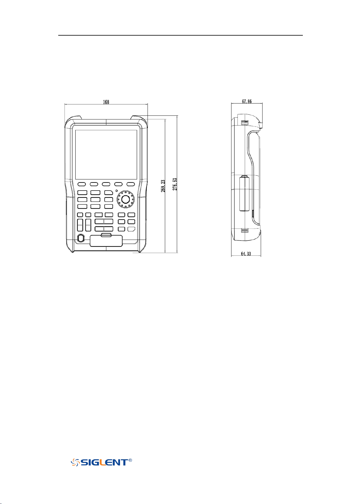
Figure 1 Front View
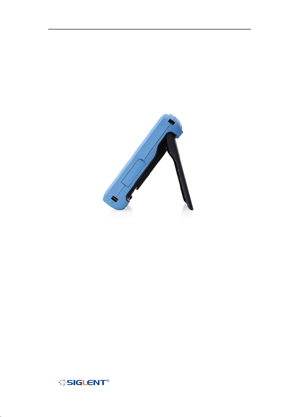
Figure 2 Side view
Appearance and Dimensions
3
Page 25
SHS800X&SHS1000X User Manual
WWW.SIGLENT.COM
Prepare for Using
Adjust the Supporting Leg
Properly adjust the supporting leg and place the oscilloscope steadily for better
operation and observation of the display screen.
Figure 3 Adjust the Supporting Leg
Battery Installation
When the oscilloscope leaves the factory, the battery and the host are separated.
Please install the battery as follows:
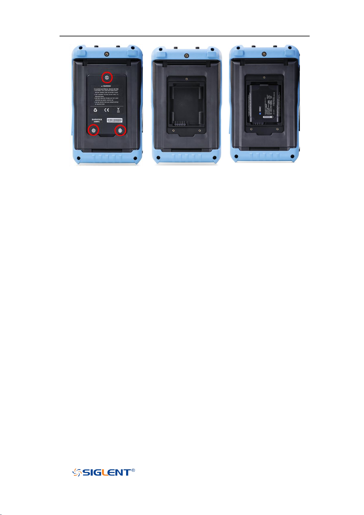
1. Remove the three screws on the battery cover with a screwdriver, as shown in
Figure 4.
2. Remove the battery cover, as shown in Figure 5.
3. Put the battery into the battery slot and close the battery cover, as shown in
Figure 6.
4. Lock the screws with the screwdriver, as shown in Figure 4, and then turn on
the oscilloscope to check whether the battery is installed successfully.
4
Page 26
SHS800X&SHS1000X User Manual
WWW.SIGLENT.COM
Figure 4
Figure 5
Figure 6
Important tips:
Pay attention to the direction of the battery cover, with the serial number at
the bottom.
Anti-reverse connection design is adopted for battery slot. Please put the
battery in gently, do not use force.
If the battery fails to power on after successful installation, it may be that the
battery has run out. Please charge it in time.
When the oscilloscope is idle, the battery needs to be charged every 3
months .
Connect the Power Supply
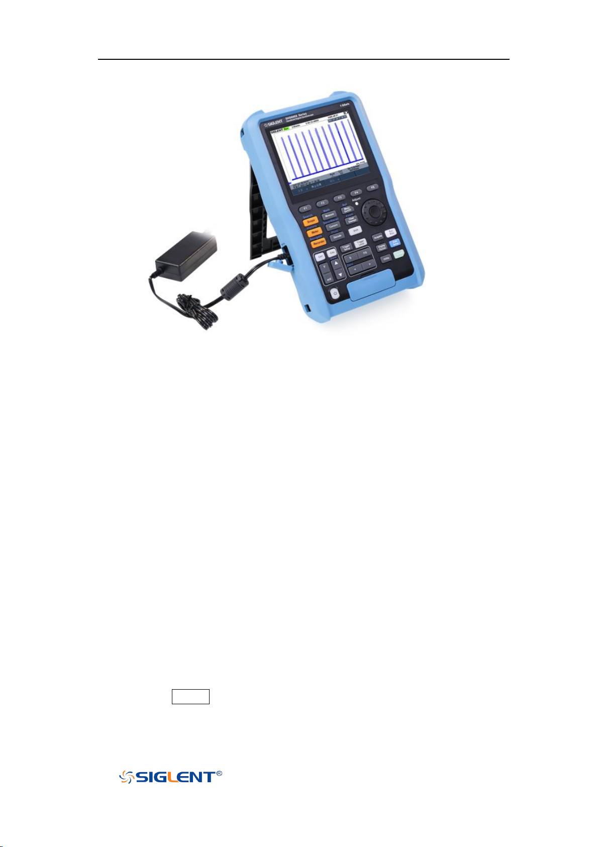
The power requirements of the oscilloscope is 100-240 V, 50/60Hz. Please use the
power cord provided to connect the oscilloscope to the power source.
5
Page 27
SHS800X&SHS1000X User Manual
WWW.SIGLENT.COM
Figure 7 Connect to Power Supply
Power-on Inspection
When the oscilloscope is energized, press the power key at the lower-left corner
of the front panel to start the oscilloscope. During the start-up process, the
oscilloscope performs a series of self-tests and you can hear the sound of relay
switching. After the self-test is finished, the welcome screen will be displayed.
Connect the Probe
Connect the Probe:
1. Connect the BNC terminal of the probe to a channel BNC connector.
2. Connect the probe tip to the circuit point to be tested and connect the ground
alligator clip of the probe to the circuit ground terminal.
Function Inspection
1. Press the Default button on the front panel to restore the instrument to its
2. Connect the ground alligator clip of the probe to the “Ground Terminal”
default configuration.
6
Page 28
SHS800X&SHS1000X User Manual
WWW.SIGLENT.COM
under the probe compensation signal output terminal.
3. Use the probe to connect the input terminal of CH1 of the oscilloscope and
the “Compensation Signal Output Terminal” of the probe.
4. Press the Auto Setup.
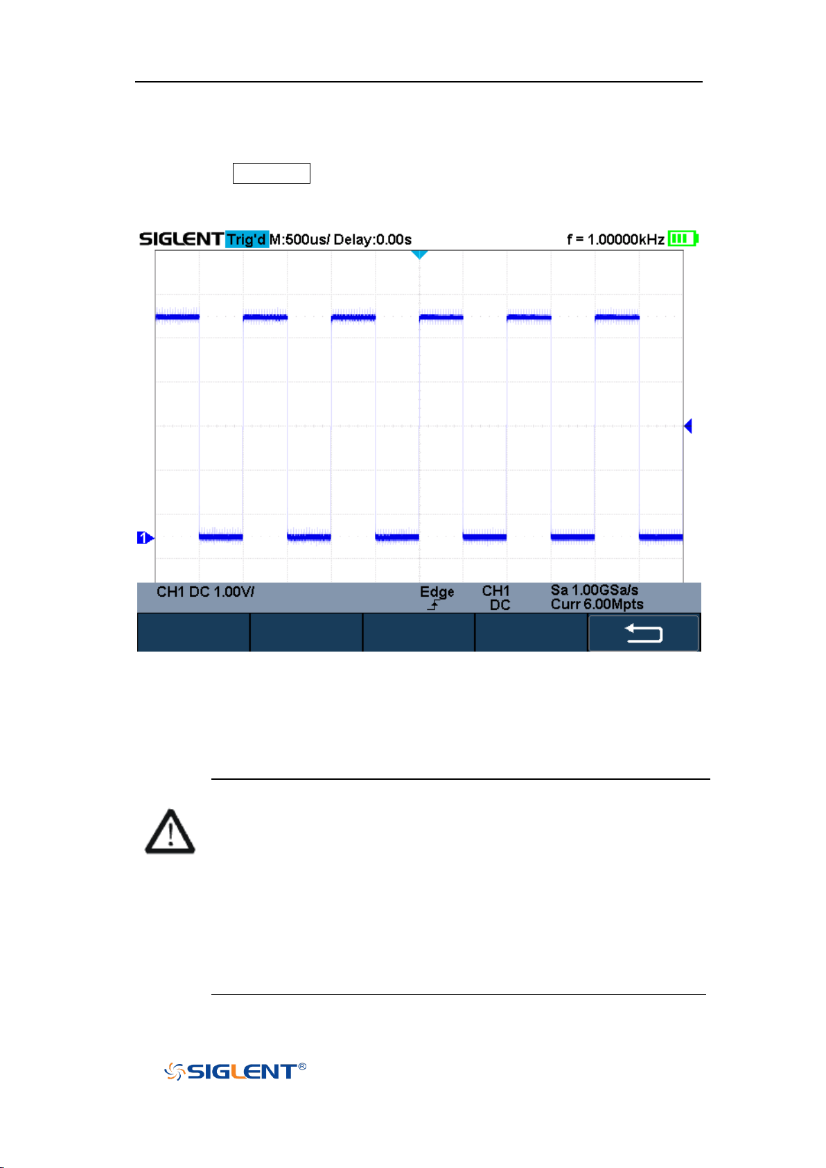
5. Observe the waveform on the display. In normal condition, the display
should be a square waveform as shown in the figure below:
Figure 8 Function Inspection
6. Use the same method to test the other channels. If the square waveforms
shown do not match that in the figure above, please perform “Probe
Compensation” in the next section.
WARNING
To avoid electric shock during the use of probe, please make sure that
the insulated wire of the probe is in good condition and do not touch
the metallic part of the probe when the probe is connected to high
voltage source
Pour éviter les chocs électriques lors de l'utilisation de la sonde,
veuillez vous assurer que le fil isolé de la sonde est en bon état et ne
touchez pas la partie métallique de la sonde lorsque la sonde est
connectée à une source haute tension
7
Page 29
SHS800X&SHS1000X User Manual
WWW.SIGLENT.COM
Probe Compensation
When the probes are used for the first time, you should compensate the probes to
match the input channels of the oscilloscope. Non-compensated or poorly
compensated probes may cause measurement inaccuracy or error. The probe
compensation procedures are as follows.
1. Set the switch to 10X on the probe.
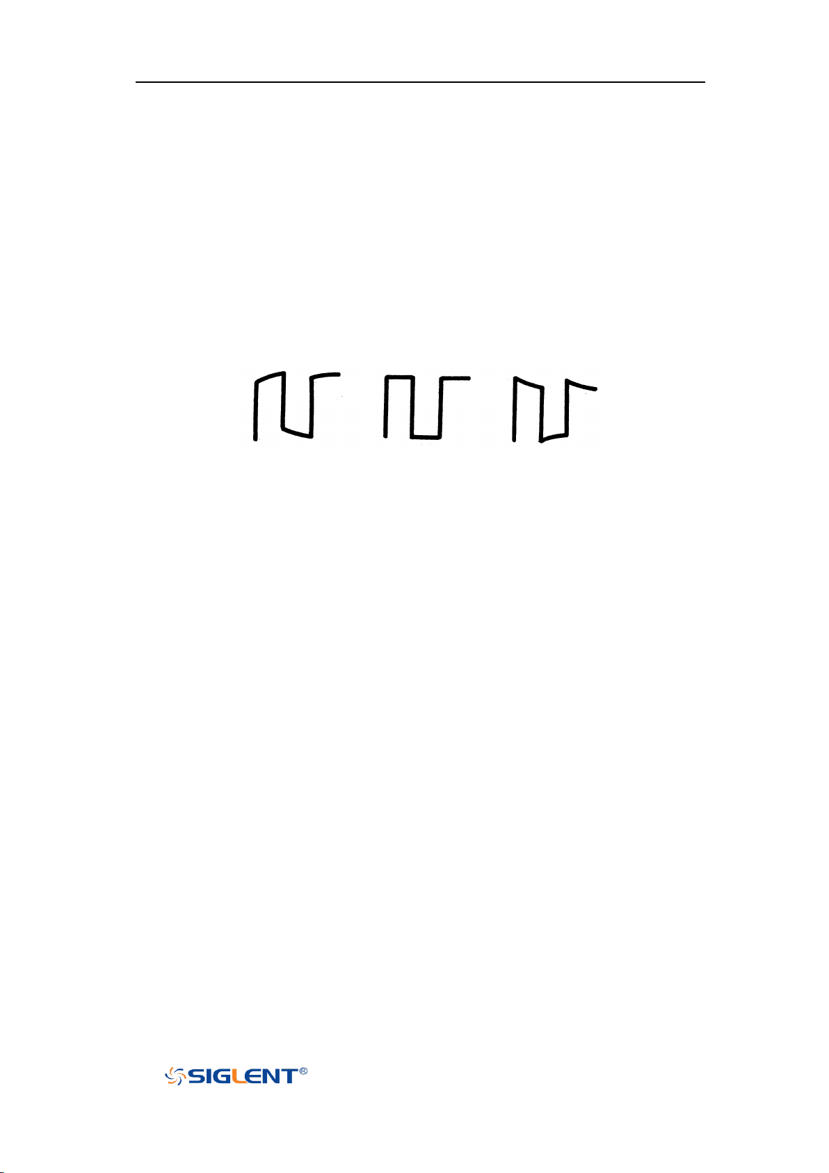
2. Perform steps 1, 2, 3 and 4 of “Function Inspection” in the previous section.
3. Check the waveforms displayed and compare them with the following:
Under Perfectly Over
Compensated Compensated Compensated
4. Use a nonmetallic driver to adjust the low-frequency compensation
adjustment hole on the probe until the waveform displayed is as the
“Perfectly compensated” in the figure above.
Multimeter Meter Pen
To avoid obtaining no measurements or unnecessary damage to the
SHS800X/SHS1000X, you should use the right jack when measuring current,
voltage and other measurement.
8
Page 30
SHS800X&SHS1000X User Manual
WWW.SIGLENT.COM
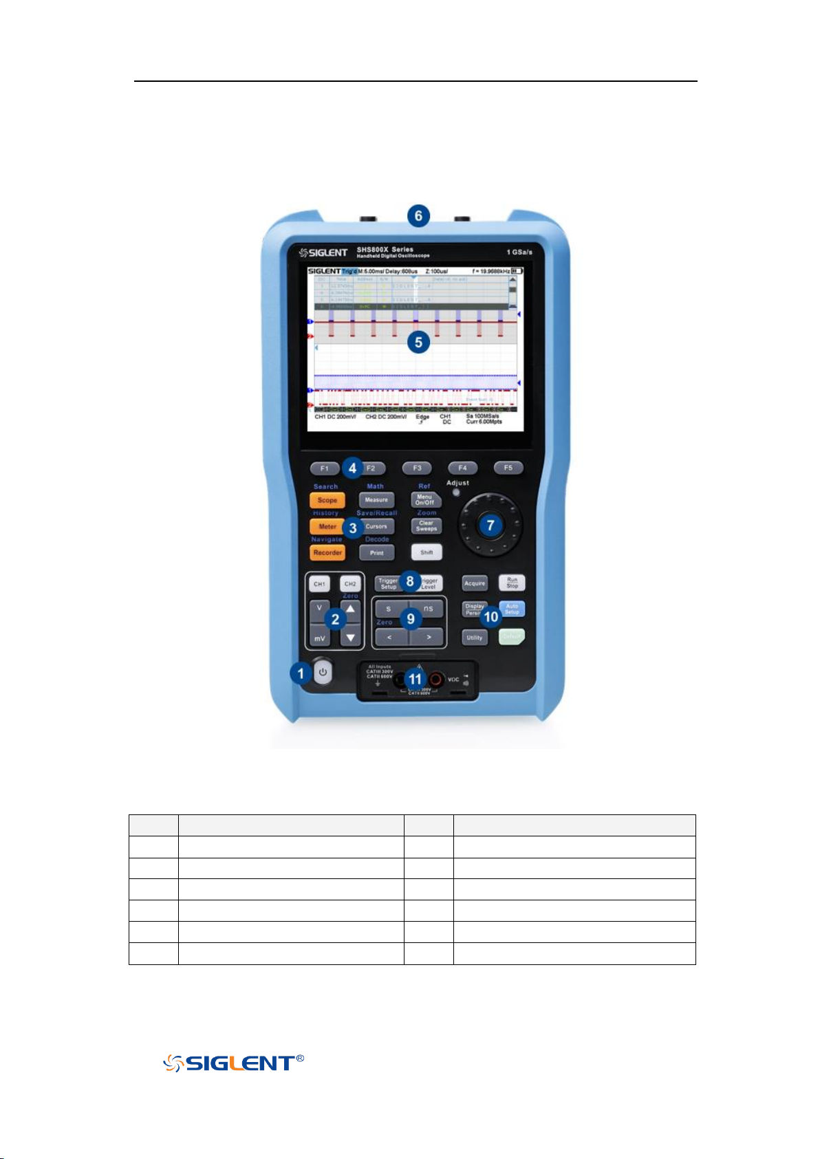
No.
Description
No.
Description
1
Power Button
7
Universal Knob
2
Vertical Control
8
Trigger Control
3
Dual Function Button
9
Horizontal Control
4
Menu Soft key
10
Single Function Button
5
LCD Display
11
Multimeter Input
6
Analog Channel Input
Front Panel Overview
Figure 9 Scope Front Panel Overview
9
Page 31
SHS800X&SHS1000X User Manual
WWW.SIGLENT.COM
Side Panel Overview
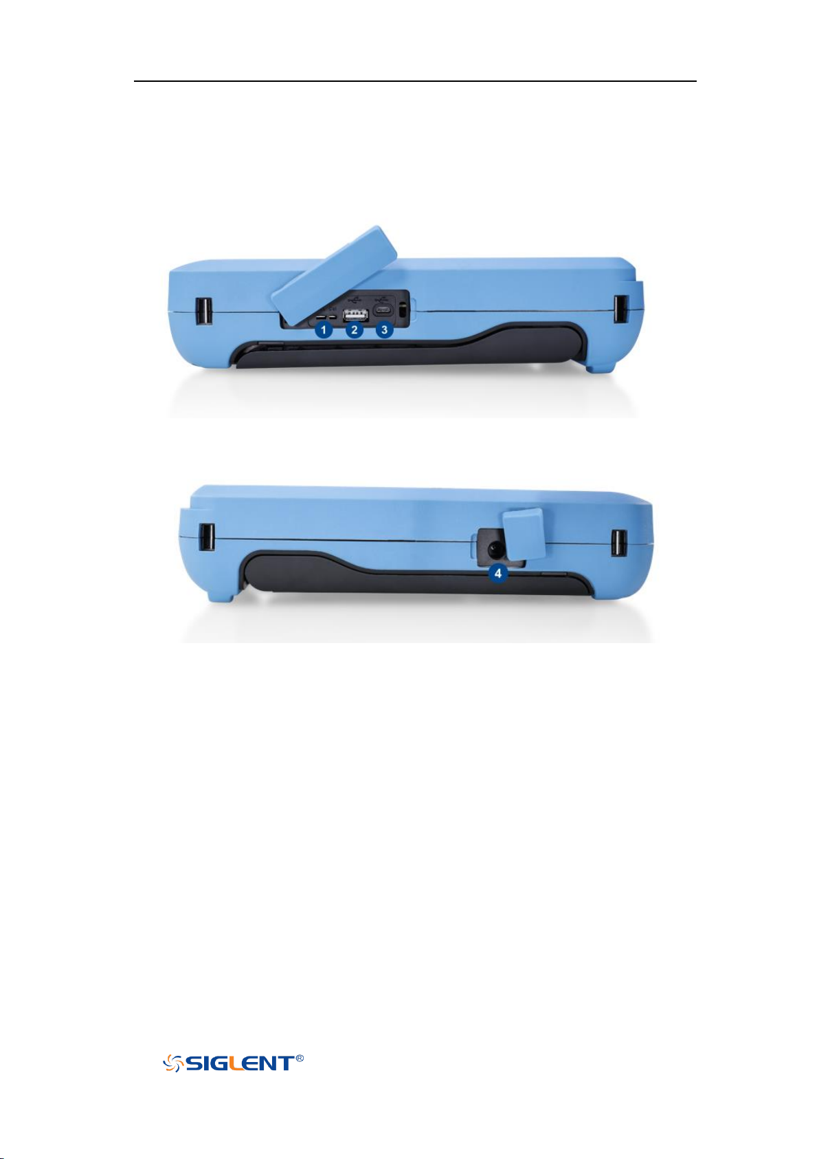
Figure 10 Scope Side Panel Overview
1. Probe Compensation/ Ground Terminal
Supplies a 0-5 V, 1 kHz square wave for compensating the probes.
2. USB Host
Connect the USB host ports to USB storage devices for data transfer.
3. USB Device
The oscilloscope support SCPI remote control commands, user can control
the oscilloscope through this interface.
4. Adapter Power Input
10
Page 32
SHS800X&SHS1000X User Manual
WWW.SIGLENT.COM
Rear Panel Overview
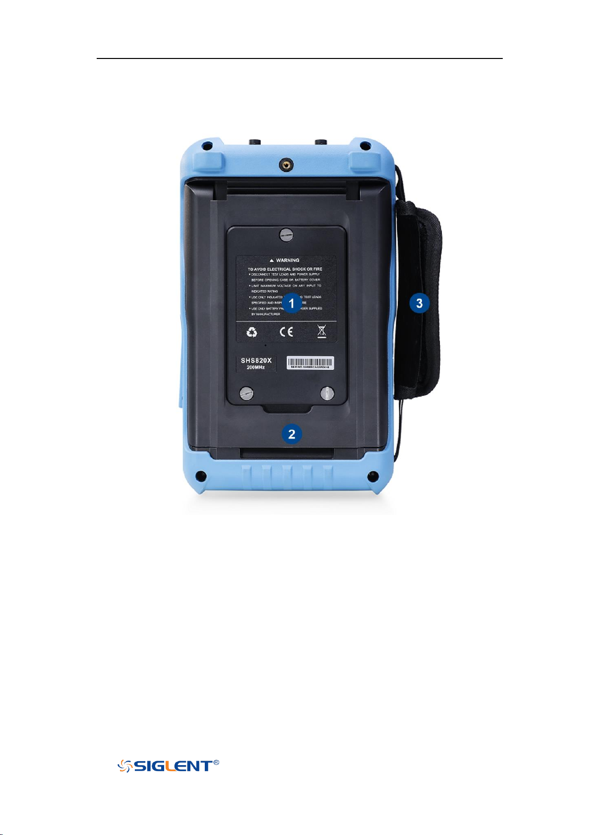
Figure 11 Scope Rear Panel Overview
1. Battery Cover
2. Supporting Leg
Adjust the supporting leg properly to use them as stands to tilt the
oscilloscope upwards for stable placement of the oscilloscope as well as
better operation and observation.
3. Handle
11
Page 33
SHS800X&SHS1000X User Manual
WWW.SIGLENT.COM
Front Panel Function Overview
Horizontal
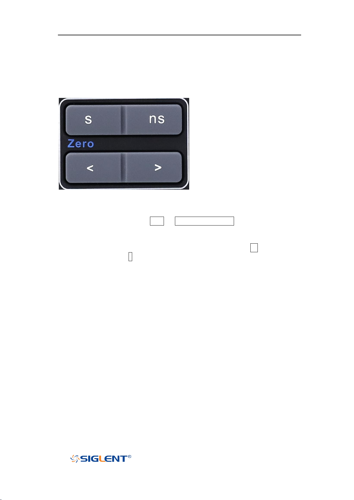
Horizontal Position Button: adjust horizontal position. Press the button to change
the horizontal delay time, waveforms of all channels will move horizontally with
the trigger point. Press the Shift + Horizontal Position to quickly reset the
horizontal delay to Zero.
Horizontal Scale Button: adjust the horizontal time base. Press ns to reduce the
time base and press s to increase the time base. During the modification,
waveforms of all the channels will be displayed in expanded or compressed
mode and the time base message at the upper-left side of the screen would
change accordingly.
12
Page 34
SHS800X&SHS1000X User Manual
WWW.SIGLENT.COM
Vertical
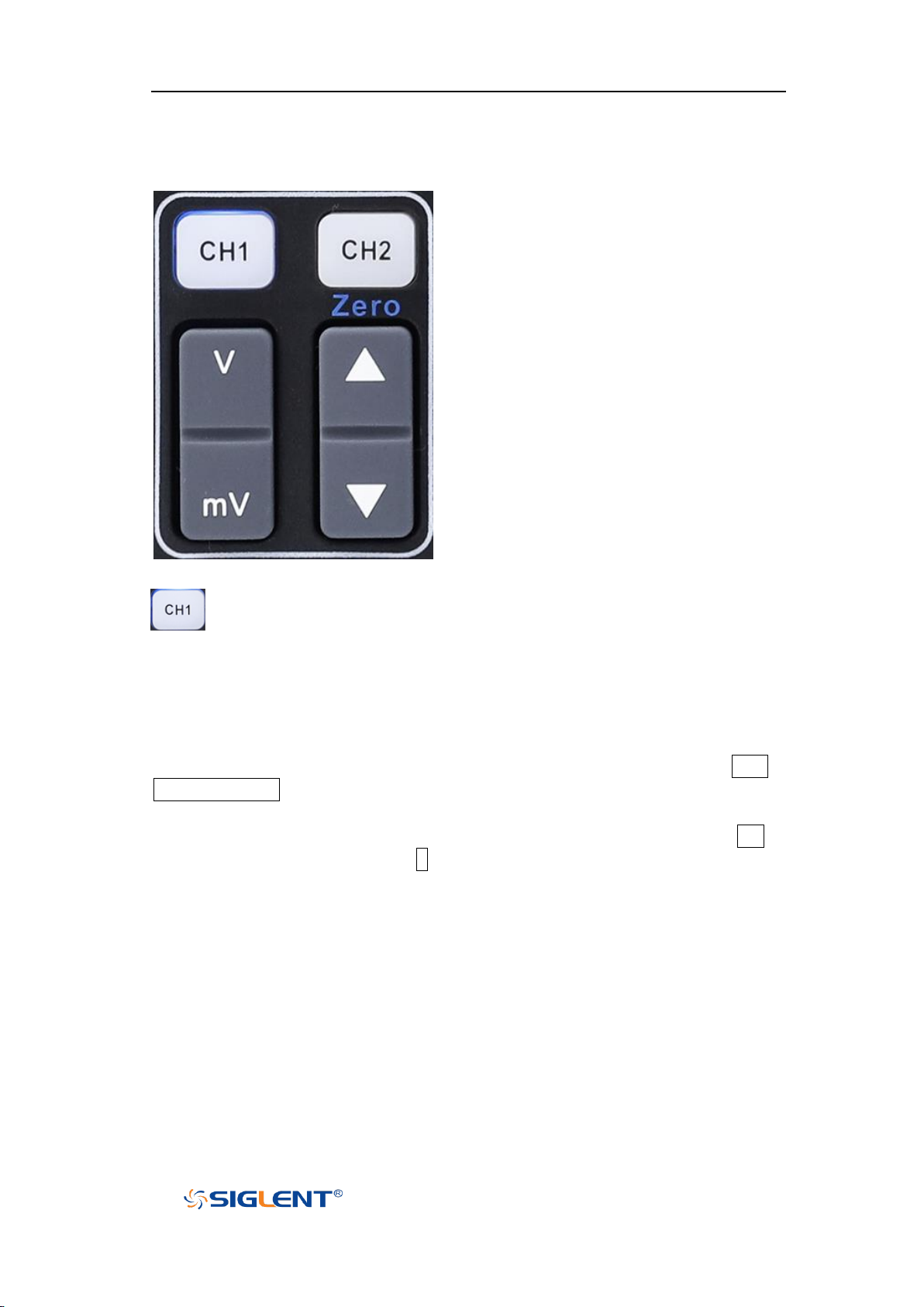
: Analog input channels. The two channels are marked by different
colors which are also used to mark both the corresponding waveforms
on the screen and the channel input connectors.
Vertical Position Button: adjust the vertical position of the current channel
waveform. Press up to increase the position and down to decrease. During the
modification, the waveform would move up and down and the position message
at the lower-left corner of the screen would change accordingly. Press Shift +
Vertical Position to quickly reset the vertical position to zero.
Vertical Scale Button: adjust the vertical scale of the current channel. Press mV to
decrease the scale and press V to increase. During the modification, the
amplitude of the waveform would enlarge or reduce and the scale information in
the channel setup box would change accordingly.
13
Page 35
SHS800X&SHS1000X User Manual
WWW.SIGLENT.COM
Trigger
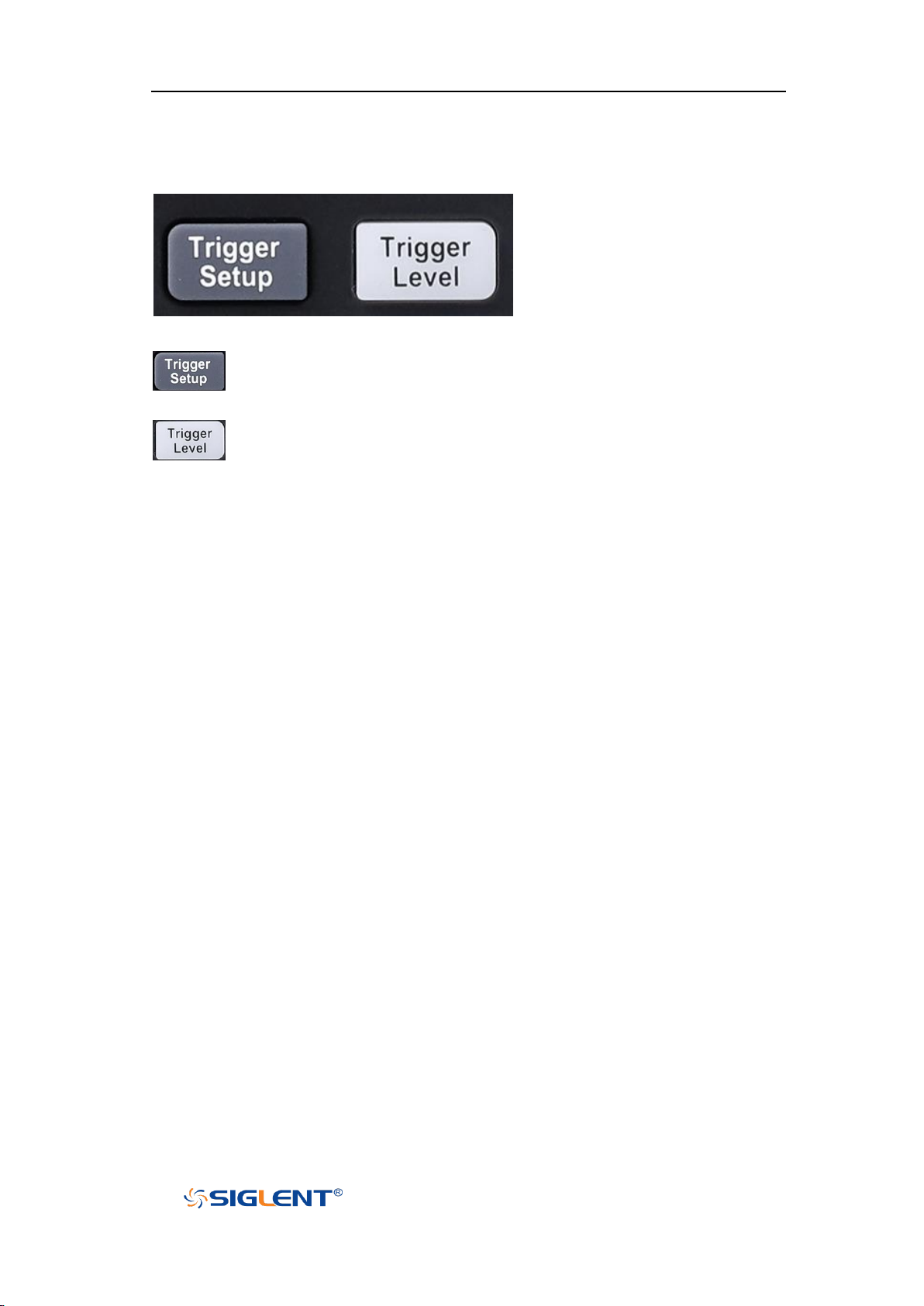
: press the button to enter the TRIGGER function menu. The
oscilloscope provides abundant advanced trigger functions.
: press the button and then turn the Universal Knob to adjust the
trigger level. During the modification, the trigger level line would
move up and down. Press down the Universal Knob to quickly reset
the trigger level to center of the waveform.
14
Page 36
SHS800X&SHS1000X User Manual
WWW.SIGLENT.COM
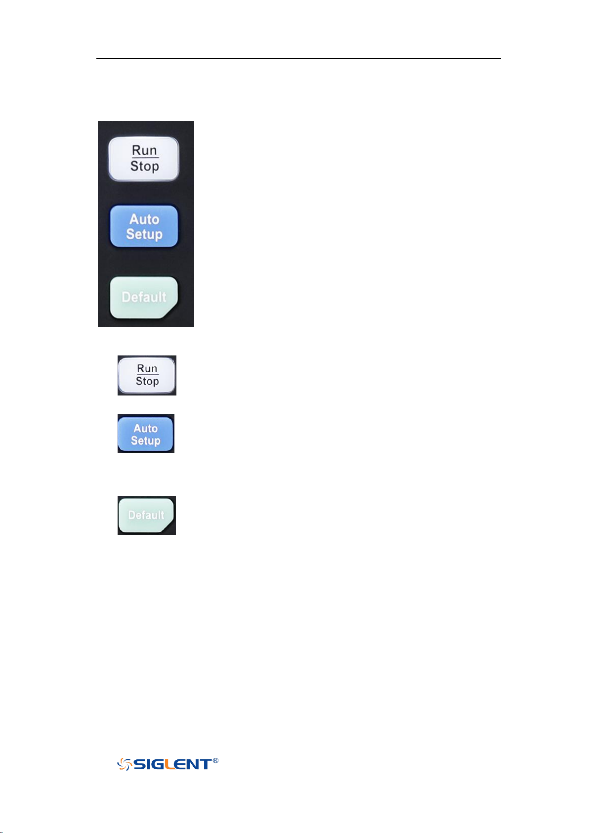
press the button to set the acquisition state to Run or Stop.
In RUN state, the key is illuminated in yellow.
In STOP state, the key is illuminated in red.
press the button to enable the waveform auto setting
function. The oscilloscope will automatically adjust the
vertical scale, horizontal time base and trigger mode
according to the input signal to realize optimum waveform
display.
Press the button to reset the oscilloscope to user default
setup.
Run Control
15
Page 37
SHS800X&SHS1000X User Manual
WWW.SIGLENT.COM
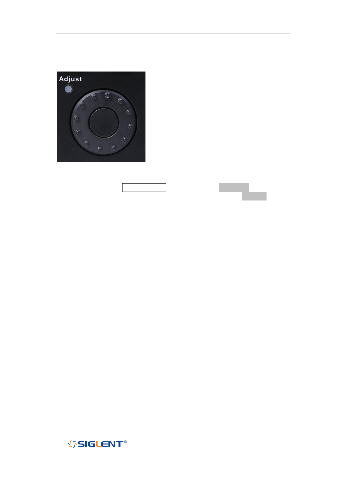
Universal Knob
1. Adjust the waveform intensity.
You can press the Display/Persist button; press the Next Page soft key to go
to the second page of the DISPLAY function menu; press the Intensity soft key
and then turn the Universal Knob to adjust the waveform intensity.
2. Select the desired submenu.
In menu operation, press any menu soft key and turn the Universal Knob to
select the desired submenu under the menu and push down the knob to
confirm the current submenu. Turn clockwise to up the intensity and
counterclockwise to down.
3. Modify parameters.
After having chosen a parameter, turn the Universal Knob to modify the
value. Turn clockwise to increase the intensity and counterclockwise to
reduce. In addition, it can also be used to adjust scale and offset of MATH
and REF.
4. Choose file or directory or input filename.
After having entered the file system, turn the Universal Knob to select the
desired file or directory. When inputting filename, turn the Universal Knob to
select the desired character and the push the knob to confirm.
16
Page 38
SHS800X&SHS1000X User Manual
WWW.SIGLENT.COM
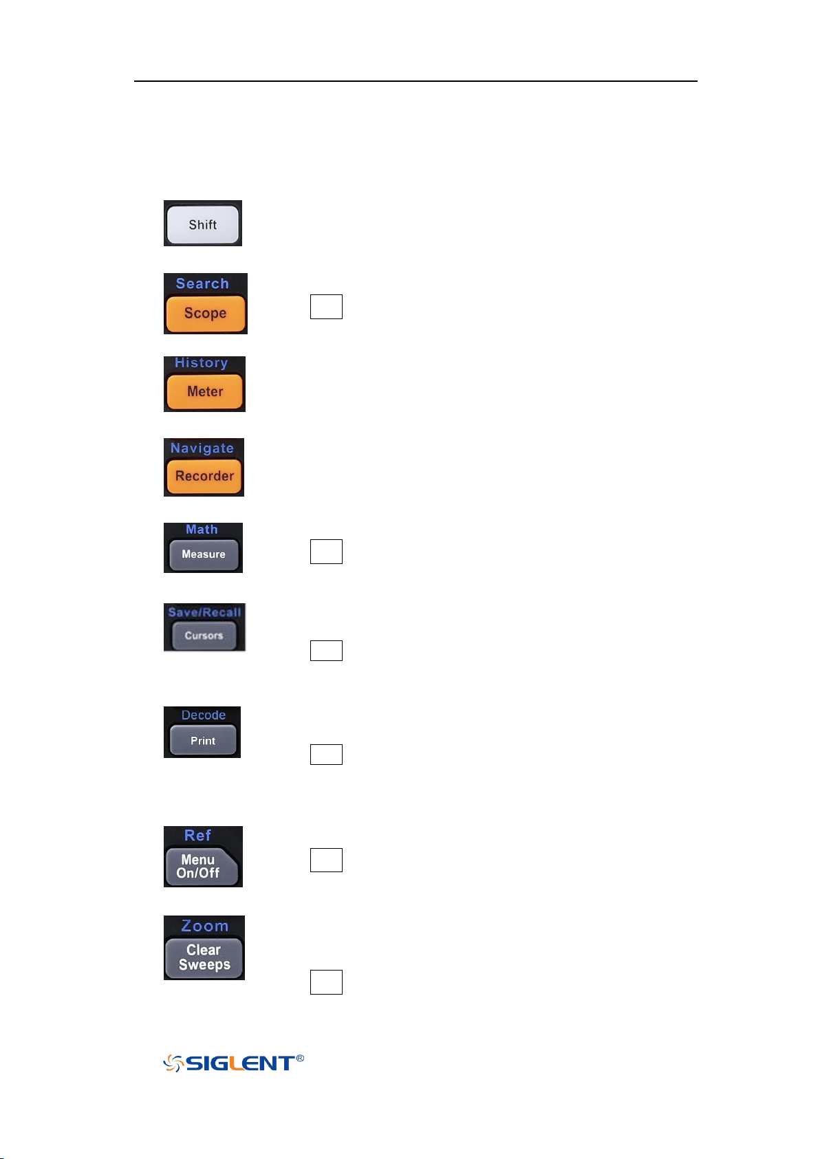
Function switching button
Press the button to enter scope mode.
Press Shift and this button to enter the SEARCH function menu.
Press the button to enter meter mode.
Press the button to enter the history mode. In history mode, it
can record most 80,000 frames waveforms.
Press the button to enter recorder mode.
Press the button to turn off or turn on the navigate function.
Press the button to enable/disable measurements.
Press Shift and this button to enable/disable MATH function.
Press to enter the CURSOR function menu. The oscilloscope
provides manual and track cursor mode.
Press Shift and this button to enter the SAVE/RECALL function
menu.
Press the button to perform a screenshot save to an external
storage device. The supported format includes .bmp\.jpg\.png.
Press Shift and this button to enter the DECODE function menu.
The oscilloscope supports I2C, SPI, UART, CAN and LIN serial bus
decode.
Press the button to turn on/off menu display.
Press Shift and this button to enter the REF function menu.
Clears the data or display in multiple sweeps, including display
persistence, measurement statistics, average sweeps and
Pass/Fail statistics.
Press Shift and this button to enter zoom mode.
Other Buttons
17
Page 39
SHS800X&SHS1000X User Manual
WWW.SIGLENT.COM
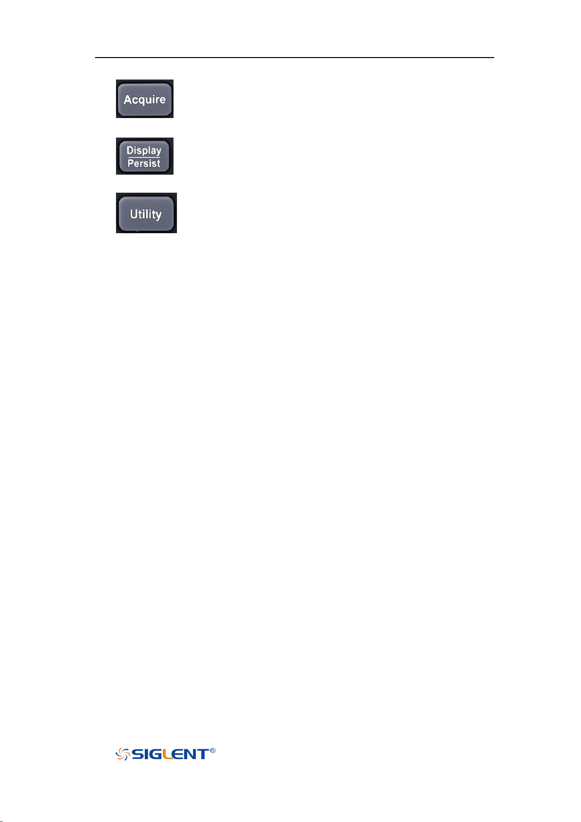
Press the button to enter the ACQUIRE function menu to set the
acquisition mode, memory depth, wave interpolation and so
on.
Press the button to enter the DISPLAY menu. The second press
turn on Persist, press the button again to turn off Persist.
Press to enter the UTILITY function menu to look at the system
status, do self-calibration, set the sound, language and so on.
18
Page 40
SHS800X&SHS1000X User Manual
WWW.SIGLENT.COM
Help
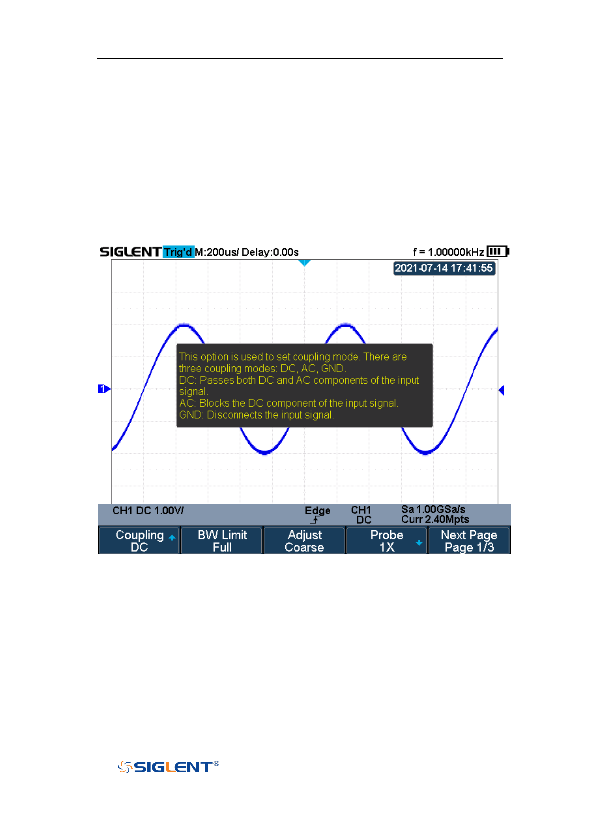
The oscilloscope has an on line help function that supplies multi-language help
information.
You can access the help function by pressing any button for 2 seconds and a help
window will explain the function. Also all of the submenus include help
information.
Figure 12 Help Message
19
Page 41
SHS800X&SHS1000X User Manual
WWW.SIGLENT.COM
User Interface
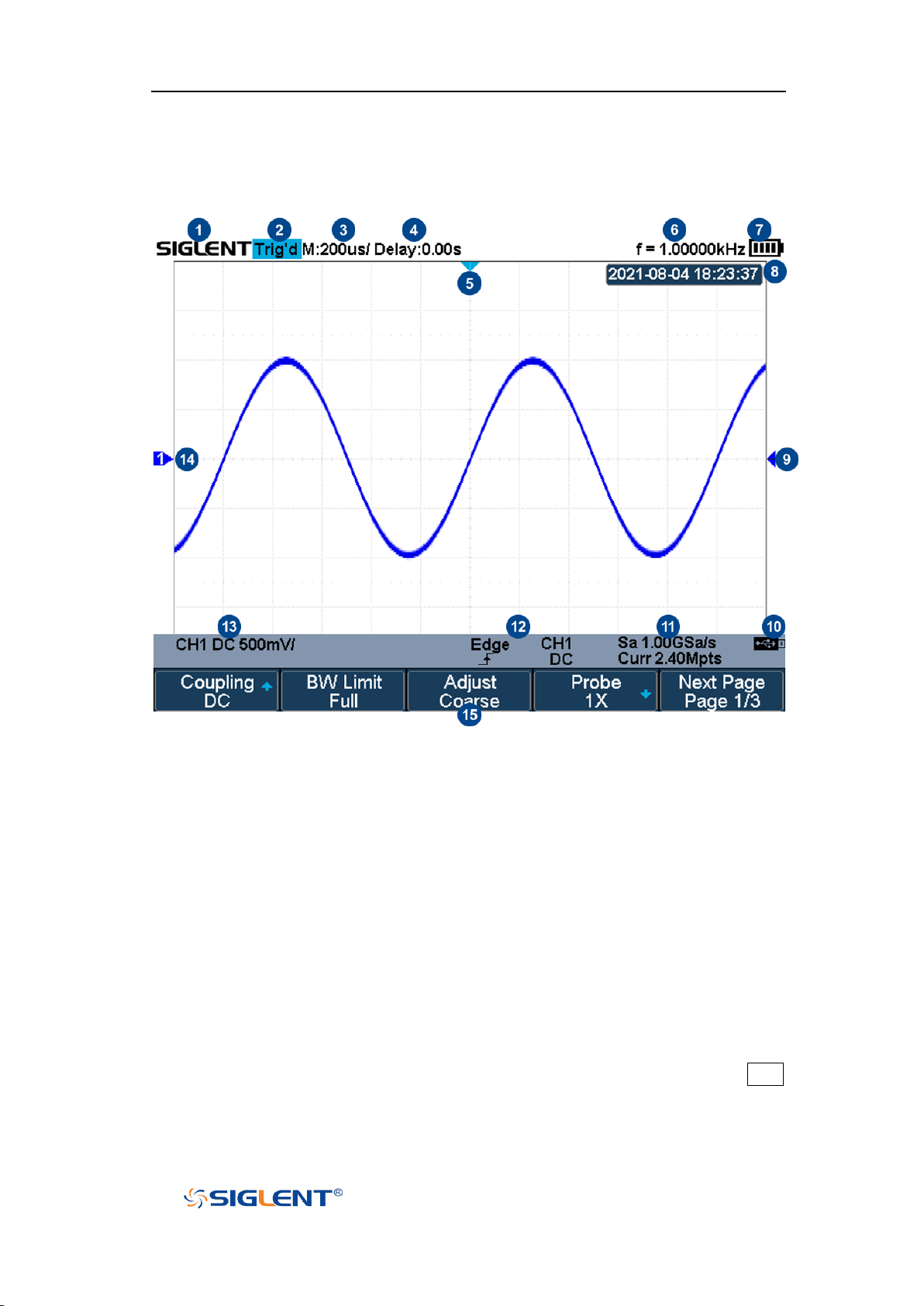
Figure 13 User Interface
1. Product Logo
SIGLENT is the registered trademark of SIGLENT TECHNOLOGIES CO., LTD.
2. Acquisition Status
Available trigger status includes Arm, Ready, Trig’d, Auto, Stop, FStop, Roll.
3. Horizontal Time Base
Represent the time per grid on the horizontal axis on the screen.
Use the Horizontal Scale button to adjust the parameter. The available
range is from 1.0 ns to 100 s.
4. Horizontal Position (Delay)
Turn the Horizontal Position button to adjust the parameter. Press the Shift
and Horizontal Position button to set the value to 0 automatically.
20
Page 42
SHS800X&SHS1000X User Manual
WWW.SIGLENT.COM
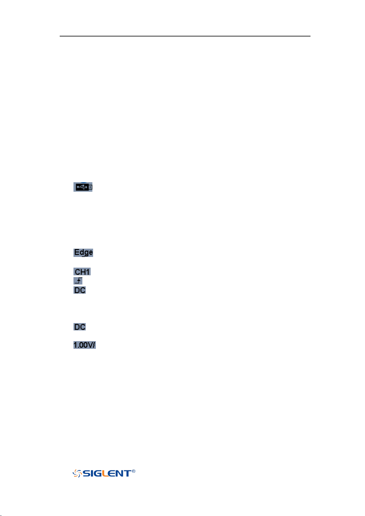
5. Trigger Delay Label
Indicate the trigger delay on the waveform.
6. Frequency Counter
Display the frequency value of the trigger channel.
7. Battery Level
8. Date/Time
9. Trigger Level Label
Display the position of trigger level, the color is the same to the trigger
channel. It can move from +4.5div to -4.5div of the screen center.
10. I/O status
Indicate that the USB Host is connected.
11. Sampling Rate/ Memory Depth
Display the current sampling rate and memory depth. Sa means the current
sampling rate and Curr means the current memory depth.
12. Trigger Setup
Trigger Type: display the current trigger type. The trigger type names
display by the abbreviation when the name is too long to display.
Trigger source: display the currently trigger source.
Trigger condition: display the current trigger condition.
Trigger coupling: display the current trigger coupling. Available trigger
coupling mode: DC, AC, HF Reject, LF Reject.
13. Channel Setup
Channel coupling: display the current channel coupling of the channel.
Channel coupling that available: DC, AC, and GND.
Vertical Scale: display the current vertical scale of the channel. Press
the Vertical Scale button to adjust the value.
14. Channel Label/Waveform
Different channels are marked by different colors and the color of the
waveform complies with the color of the channel.
15. Menu
Display the corresponding function menu of the selected button. Press the
corresponding soft key to set the oscilloscope.
21
Page 43

SHS800X&SHS1000X User Manual
WWW.SIGLENT.COM
Vertical System
This chapter introduces how to set the vertical system of the oscilloscope.
The contents of this chapter:
Enable the Channel
Adjust Scale
Vertical Position
Coupling
Bandwidth Limit
Probe
Unit
Deskew
Invert
Trace Visible/Hidden
22
Page 44

SHS800X&SHS1000X User Manual
WWW.SIGLENT.COM
Enable the Channel
The SHS800X/SHS1000X provides 2 analog input channels and each channel
shares the same vertical control system. Since the vertical system setting
methods of each channel is the same, this chapter uses CH1 as an example to
introduce the setting method of the vertical system.
Connect the signal to the CH1 channel connector; and then press the CH1 button
in the vertical control area (VERTICAL) on the front panel to enable CH1.
The channel setting menu and the channel information bar are displayed at the
bottom of the screen.
After the channel is turned on, modify the parameters such as the vertical scale,
the horizontal time base and the trigger mode according to the input signal to
make the waveform display easy to observe and measure.
Note: to turn off the channel, press the channel button twice.
23
Page 45

SHS800X&SHS1000X User Manual
WWW.SIGLENT.COM
Adjust Scale
The vertical scale can be adjusted in Coarse or Fine mode.
Coarse adjustment (take counterclockwise as an example): set the vertical
scale in 1-2-5 step namely 2 mV/div, 5 mV/div, 10 mV/div …10 V/div.
Fine adjustment: further adjust the vertical scale within a relatively smaller
range to improve vertical resolution. For example: 2 V/div, 1.98V/div,
1.96V/div, 1.94 V/div …1 V/div.
If the amplitude of the input waveform is a little bit greater than the full scale
under the current scale and the amplitude would be a little bit lower if the
next scale is used, fine adjustment can be used to improve the amplitude of
waveform display to view signal details.
Press the CH1 button on the front panel; then press the Adjust soft key to select
the desired mode. Press the Vertical Scale button to adjust the vertical scale (V to
increase the scale and mV to reduce).
The scale information in the channel information bar at the bottom of the screen
will change accordingly during the adjustment process. The adjustable range of
the vertical scale is related to the probing ratio currently set. By default, the probe
attenuation factor is 1X and the adjustable range of the vertical scale is from 2
mV/div to 100 V/div.
24
Page 46
SHS800X&SHS1000X User Manual
WWW.SIGLENT.COM
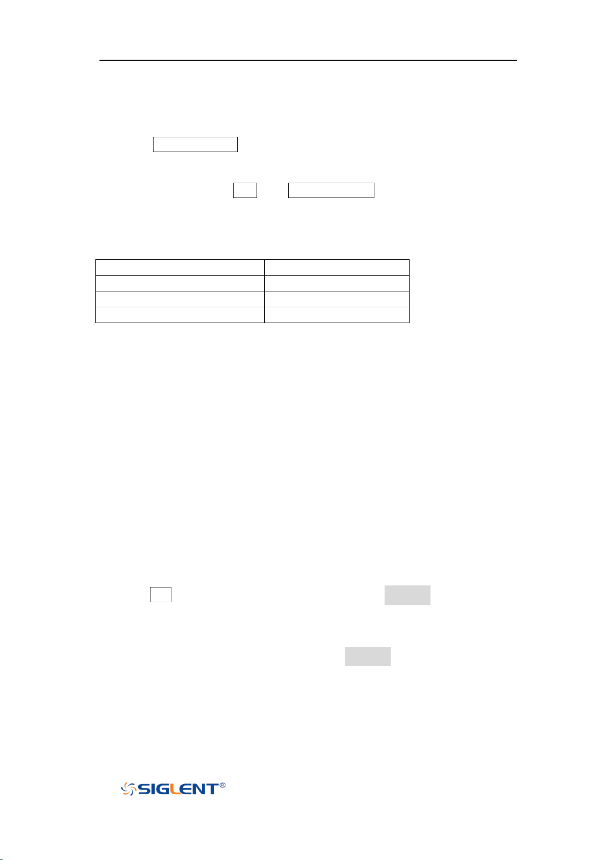
Volt Scale
Range of Vertical Position
2 mV/div ~ 296 mV/div
±5 V
302 mV/div ~ 7.5 V/div
±80 V
7.6 V/div ~ 100 V/div
±400 V
Vertical Position
Press the Vertical Position button to adjust the vertical position of the channel
waveform. Press up to increase the vertical position and the channel waveform
moves up, while press down to decrease the vertical position and the waveform
moves down. Press the Shift and Vertical Position button to set the vertical
position of the channel waveform to zero.
The table below shows the range of vertical positions according to the volt scale.
Coupling
Set the coupling mode to filter out the undesired signals. For example, the signal
under test is a square waveform with DC offset.
When the coupling mode is set to DC: the DC and AC components of the
signal under test can both pass through the channel.
When the coupling mode is set to AC: the DC components of the signal under
test are blocked.
When the coupling mode is set to GND: the DC and AC components of the
signal under test are both blocked.
Press the CH1 button on the front panel; then press the Coupling softkey and turn
the Universal Knob to select the desired coupling mode. The default setup is DC.
The current coupling mode is displayed in the channel information bar at the
bottom of the screen. You can also press the Coupling softkey continuously to
switch the coupling mode.
25
Page 47

SHS800X&SHS1000X User Manual
WWW.SIGLENT.COM
Menu
Attenuation Factor
0.1X
0.1 : 1
0.2X
0.2 : 1
0.5X
0.5 : 1
1X
1 : 1
2X
2 : 1
… … 5000X
5000 : 1
10000X
10000 : 1
Bandwidth Limit
Set the bandwidth limit to reduce display noise. For example, the signal under
test is a pulse with high frequency oscillation.
When the bandwidth limit is set to Full, the high frequency components of the
signal under test can pass through the channel.
When the bandwidth limit is set to 20M, the high frequency components that
exceed 20 MHz will be attenuated.
Press the CH1 button on the front panel; then press the BW Limit softkey to select
Full or 20M. The default setup is Full. When the bandwidth limit is enabled, the
character B will be displayed in the channel information bar at the bottom of the
screen.
Probe
Set the probe attenuation factor to match the type of the probe that you are using
to ensure correct vertical readouts.
Press the CH1 button on the front panel; then press the Probe softkey and turn
the Universal Knob to select the desired value, and push the knob to confirm. The
default setup is 1X.
You can also continuously press the Probe softkey to switch the probe
attenuation factor.
The table shows the probe attenuation factor
26
Page 48
SHS800X&SHS1000X User Manual
WWW.SIGLENT.COM
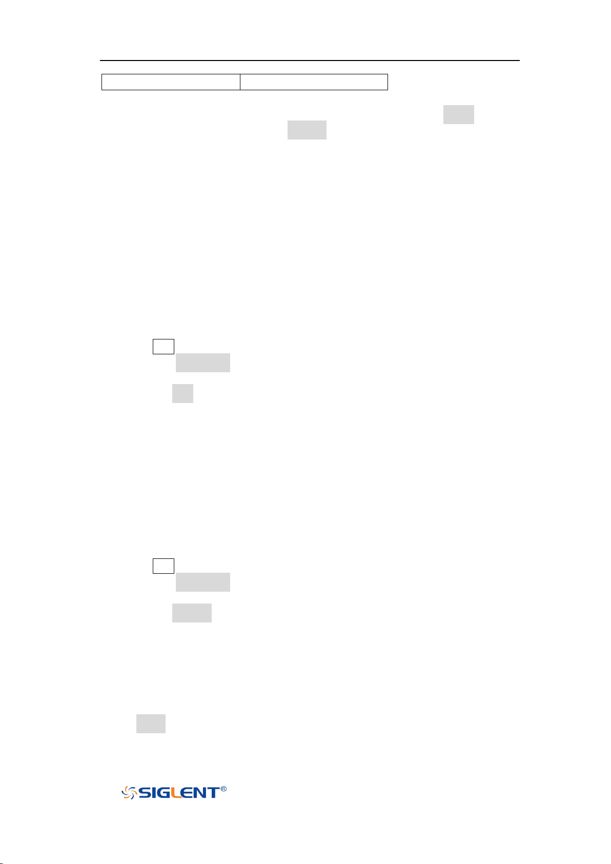
Custom
1000000:1~0.000001:1
You can also customize the probe attenuation factor. Press the Probe softkey,
select Custom, and then press the Custom softkey to select Custom or Custom
Fine. First, select Custom and turn the Universal Knob to achieve rough
adjustment; and then select Custom Fine and turn the Universal Knob to achieve
fine adjustment.
Unit
Select the amplitude display unit for the current channel. The available units are
V and A. When the unit is changed, the unit displayed in the channel information
bar will change accordingly.
1. Press CH1 button on the front panel to enter the CH1 function menu.
2. Press the Next Page softkey to enter the second page of the CH1 function
menu.
3. Press the Unit softkey to select the desired unit V or A.
The default setup is V.
Deskew
The valid range of each analog channel is ±100ns.
1. Press CH1 button on the front panel to enter the CH1 function menu.
2. Press the Next Page softkey to enter the second page of the CH1 function
menu.
3. Press the Deskew softkey. Then turn the Universal Knob to change deskew.
Invert
When Invert is set to On, the voltage values of the displayed waveform are
inverted. Invert affects how a channel is displayed while it keeps the trigger
27
Page 49
SHS800X&SHS1000X User Manual
WWW.SIGLENT.COM
Trace Visible
Trace Hidden
settings.
Inverting a channel also changes the result of any math function selected and
measure function.
1. Press CH1 button on the front panel to enter the CH1 function menu.
2. Press the Next Page softkey to enter the second page of the CH1 function
menu.
3. Press the Invert softkey to turn on or off the invert display.
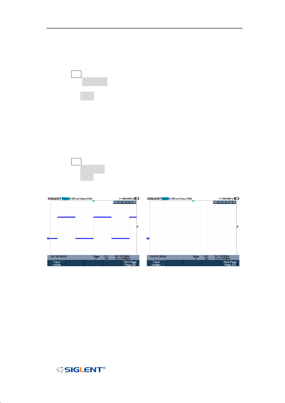
Trace Visible/Hidden
Set whether to hide the current channel waveform
1. Press CH1 button on the front panel to enter the CH1 function menu.
2. Press the Next Page softkey to enter the third page of the CH1 function menu.
3. Press the Trace softkey to show or hide the channel waveform
28
Page 50

SHS800X&SHS1000X User Manual
WWW.SIGLENT.COM
Horizontal System
This chapter introduces how to set the horizontal system of the oscilloscope.
The contents of this chapter:
Horizontal Scale
Horizontal Delay
Roll Mode
Zoom Mode
29
Page 51
SHS800X&SHS1000X User Manual
WWW.SIGLENT.COM
Horizontal Scale
Press the Horizontal Scale button on the front panel to adjust the horizontal time
base. Press the ns to decrease the horizontal time scale and press the s to
increase.
The time base information at the upper left corner of the screen will change
accordingly during the adjustment. The range of the SHS800X/SHS1000X
horizontal scale is from 1ns/div to 100s/div.
The Horizontal Scale button works (in the Normal time mode) while acquisitions
are running or when they are stopped. When in run mode, adjust the horizontal
scale knob to change the sample rate. When stopped, adjust the horizontal scale
knob to zoom in the acquired data.
30
Page 52

SHS800X&SHS1000X User Manual
WWW.SIGLENT.COM
Horizontal Delay
Press the Horizontal Position button on the front panel, the trigger point (solid
inverted triangle) will move horizontally. The trigger point moves horizontally to
the right when press > , while moves to left when press < . Press the Shift and
Horizontal Position button to reset the trigger delay.
When changing the horizontal delay, the delay time displayed in the information
bar at the top of the screen changes in real time, indicating the distance between
the time reference point and the trigger point. The available delay range
depends on the selected time/div and memory depth.
31
Page 53

SHS800X&SHS1000X User Manual
WWW.SIGLENT.COM
Roll Mode
Press the Acquire button to enter the acquire menu and press the Roll Mode
softkey to enable the roll mode.
In Roll mode the waveform moves slowly across the screen from right to left. It
only operates on time base settings of 50 ms/div or slower.
In Roll mode there is no trigger. The fixed reference point on the screen is the
right edge of the screen and refers to the current moment in time. Events that
have occurred are scrolled to the left of the reference point. Since there is no
trigger, no pre- trigger information is available.
If you would like to stop the display in Roll mode, press the Run/Stop button. To
clear the display or restart an acquisition in Roll mode, press the Run/Stop button
again.
Use Roll mode on low- frequency waveforms to yield a display much like a strip
chart recorder. It allows the waveform to roll across the display.
32
Page 54
SHS800X&SHS1000X User Manual
WWW.SIGLENT.COM
Zoom Mode
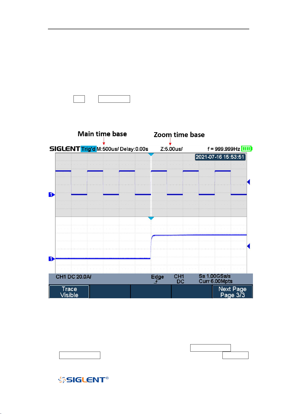
Zoom is a horizontally expanded version of the normal display. You can use
Zoom to locate and horizontally expand part of the normal window for a more
detailed (higher- resolution) analysis of signals.
Press the Shift and Clear Sweep button on the front panel to turn on the zoom
function, and press the combination buttons again to turn off the function. When
Zoom function is on, the display window split in half. The top half shows the main
window and the bottom half displays a faster zoom window.
The extended normal window area is outlined with a border, and the rest of the
normal window is ghosting. This border area in the normal window is zoomed to
the lower half.
To change the time base for the Zoom window, press the Horizontal Scale button.
The Horizontal Scale button controls the size of the border area. The Horizontal
Figure 14 Split Screen Zoom
33
Page 55

SHS800X&SHS1000X User Manual
WWW.SIGLENT.COM
Position button sets the left- to- right position of the zoom window. The delay
value, which is the time displayed relative to the trigger point is momentarily
displayed in the upper- right corner of the display when press the Horizontal
Position button. Negative delay values indicate you're looking at a portion of the
waveform before the trigger event, and positive values indicate you're looking at
the waveform after the trigger event.
To change the time base of the normal window, turn off Zoom; then press the
Horizontal Scale button.
34
Page 56

SHS800X&SHS1000X User Manual
WWW.SIGLENT.COM
Acquisition System
This chapter introduces how to use the acquisition control and set the sampling
system of the oscilloscope.
The contents of this chapter:
Overview
Memory Depth
Sampling Mode
Interpolation Method
Acquisition Mode
Horizontal Format
Sequence Mode
35
Page 57
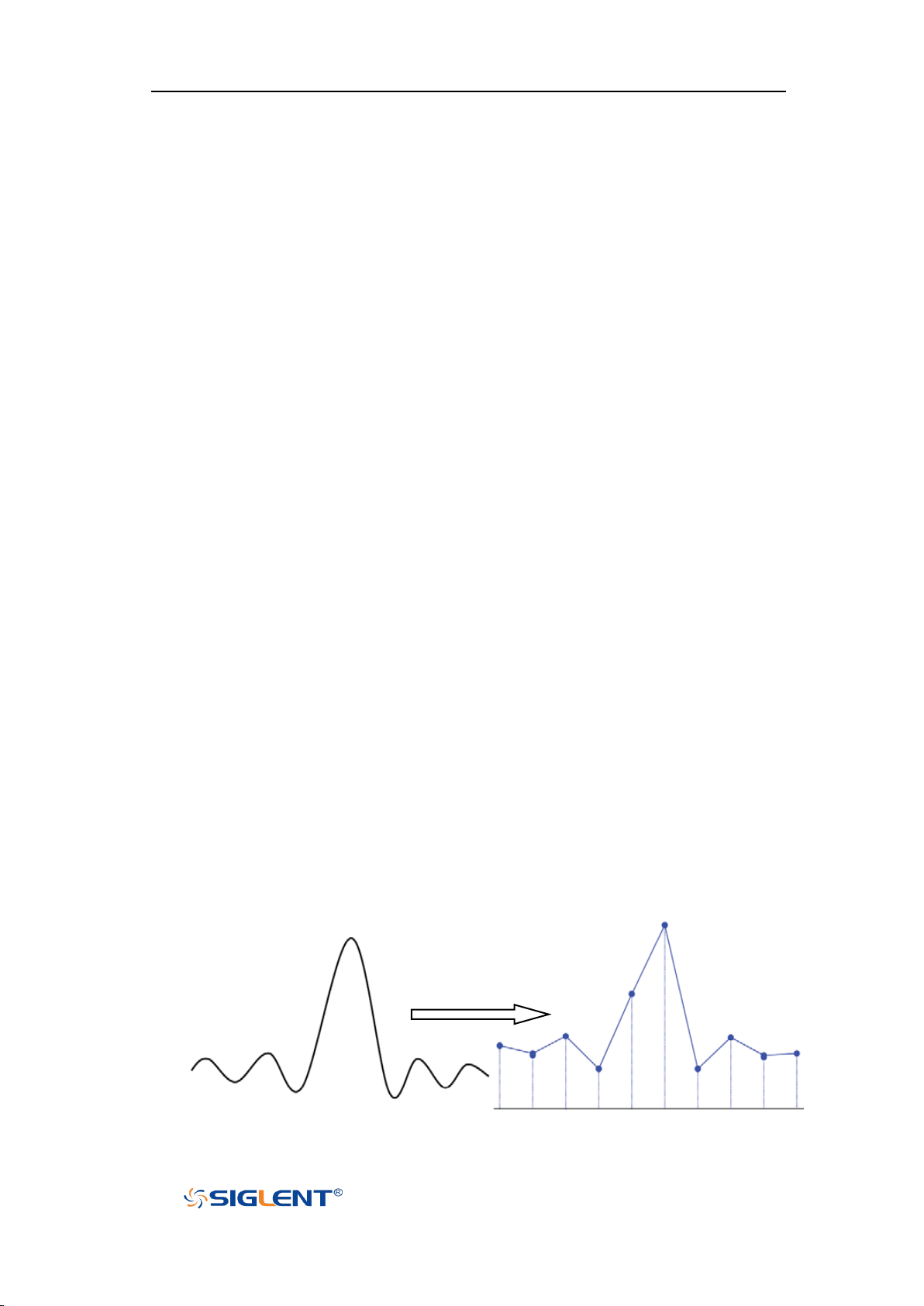
SHS800X&SHS1000X User Manual
WWW.SIGLENT.COM
Overview
To understand the oscilloscope's sampling and acquisition modes, it is helpful to
understand sampling theory, sample rate and oscilloscope bandwidth and
sample rate.
Sampling Theory
The Nyquist sampling theorem states that for a limited bandwidth (band- limited)
signal with maximum frequency f
must be greater than twice the maximum frequency f
reconstruct the signal without aliasing.
f
= f
MAX
= Nyquist frequency (fN) = folding frequency
S/2
, the equally spaced sampling frequency fS
MAX
, in order to uniquely
MAX
Sample Rate
The maximum sample rate of the oscilloscope is 1GSa/s. The actual sample rate
of the oscilloscope is determined by the horizontal scale. Press the Horizontal
Scale Button to adjust the sample rate.
The actual sample rate is displayed in the information area at the bottom right
corner of the screen.
The effect of low sampling rate on the waveform:
1. Waveform Distortion: when the sample rate is too low, some waveform
details are lost and the waveform displayed is quite different from the actual
signal.
36
Page 58
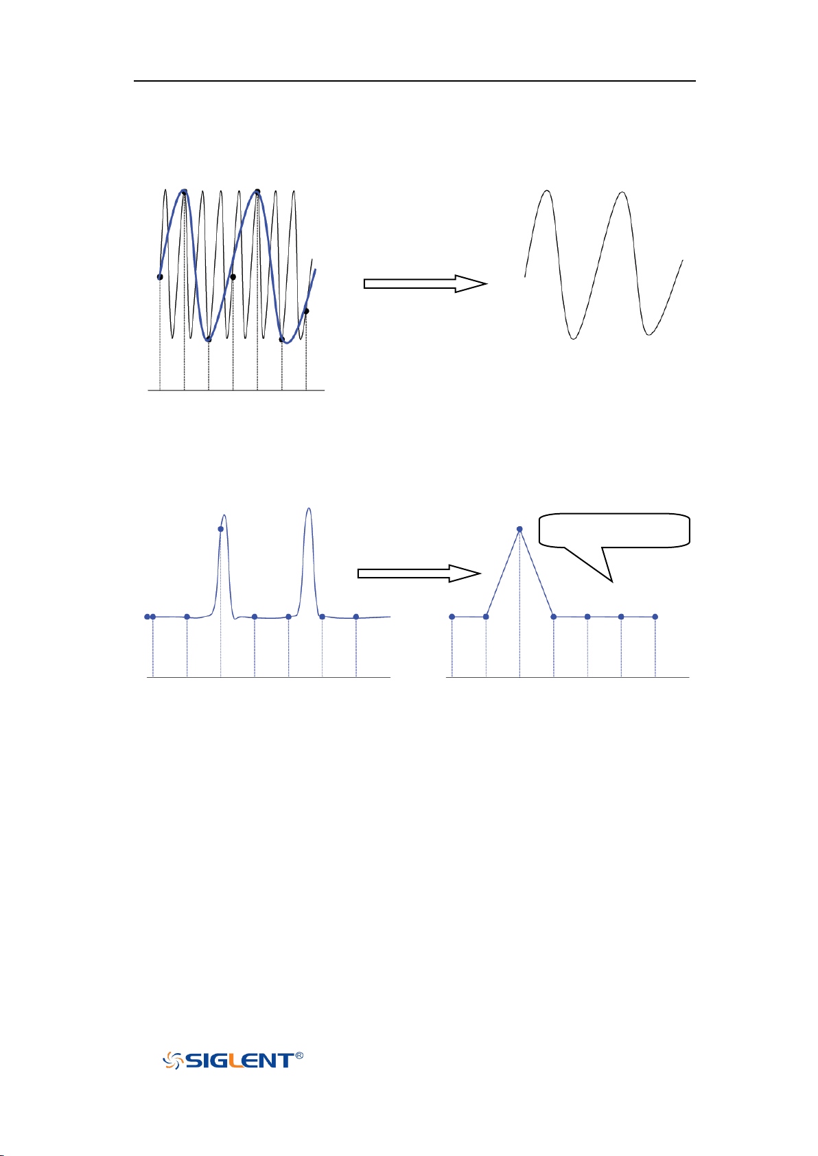
SHS800X&SHS1000X User Manual
WWW.SIGLENT.COM
Pulse disappeared
2. Waveform Confusion: when the sample rate is lower than twice the actual
signal frequency (Nyquist Frequency), the waveform frequency reconstructed
from the sample data is lower than the actual signal frequency. The most
common aliasing is the jitter on fast edge.
3. Waveform Leakage: when the sample rate is too low, the waveform
reconstructed from the sample data cannot reflect all the actual signal
information.
Bandwidth and Sample Rate
An oscilloscope's bandwidth is typically described as the lowest frequency at
which the input sinusoidal signal is attenuated by 3 dB (- 30% amplitude error).
Under the bandwidth frequency, the required sampling rate is fS = 2fBW according
to the sampling theory. However, the theory assumes that there are no frequency
components above f
requires a system with an ideal brick wall frequency response.
(fBW in this case) in the system, which means that it
MAX
37
Page 59
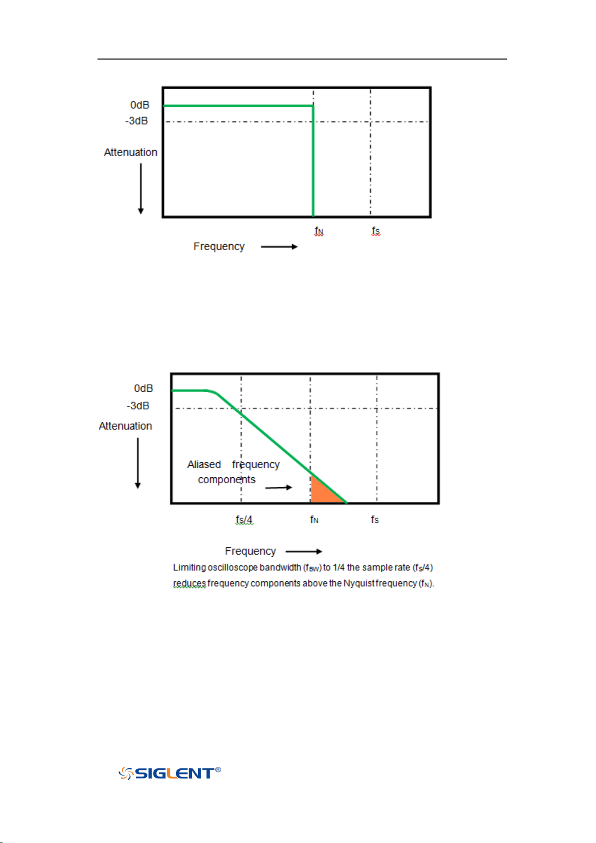
SHS800X&SHS1000X User Manual
WWW.SIGLENT.COM
In fact, digital signals have frequency components above the fundamental
frequency (a square wave is composed of a sine wave of the fundamental
frequency and numerous odd harmonics), and generally, for oscilloscopes with a
bandwidth of 500 MHz and below, the system has a Gaussian frequency
response.
Therefore, the sampling frequency of the oscilloscope should be four or more
times the bandwidth frequency: fS = 4fBW. In this way, there is less aliasing, and
the components in the aliasing area are attenuated a lot.
38
Page 60
SHS800X&SHS1000X User Manual
WWW.SIGLENT.COM
Single Channel Mode
Dual Channel Mode
12k
6k
120k
60k
1.2M
600k
12M
6M
Memory Depth
Memory depth refers to the number of waveform points that the oscilloscope can
store in a single trigger sample and it reflects the storage ability of the sample
memory.
Press the Acquire button on the front panel; press the Mem Depth softkey and
then turn the Universal Knob to select the desired value and push down the knob
to confirm. Press the Mem Depth softkey continually can also select the desired
value.
The actual memory depth is displayed in the information area at the bottom right
corner of the screen. Since the oscilloscope has two acquisition memories, when
only one channel is on, the maximal memory depth is up to 12 Mpts.
The maximum storage depth in single channel mode is twice that in dual channel
mode, as shown in the following table:
The relation of memory depth, sample rate, and waveform length fulfills the
equation below:
Memory depth = sample rate (Sa/s) × waveform length (s/div × div)
39
Page 61

SHS800X&SHS1000X User Manual
WWW.SIGLENT.COM
Sampling Mode
The oscilloscope only supports real-time sampling. In this mode, the oscilloscope
samples and displays waveform within a trigger event. The maximum real-time
sample rate is 1GSa/s.
Press the Run/Stop button to stop the sample, and the oscilloscope will hold the
last display. At this point, you can still use the vertical control and horizontal
control to pan and zoom the waveform.
40
Page 62

SHS800X&SHS1000X User Manual
WWW.SIGLENT.COM
Interpolation Method
Under real-time sampling, the oscilloscope acquires the discrete sample values
of the waveform being displayed. In general, a waveform of dots display type is
very difficult to observe. In order to increase the visibility of the signal, the digital
oscilloscope usually uses the interpolation method to display a waveform.
The interpolation method is a processing method to “connect all the sampling
points”, and using some points to calculate the whole appearance of the
waveform. For real-time sampling interpolation method is used, even if the
oscilloscope in a single captures only a small number of sampling points. The
oscilloscope can use the interpolation method to fill out the gaps between points
and reconstruct an accurate waveform.
Press the Acquire button on the front panel to enter the ACQUIRE Function menu;
then press the Interpolation softkey to select Sinx/x or X.
X: In the adjacent sample points are directly connected on a straight line.
This method is only confined to rebuild on the edge of signals, such as a
square wave.
Sinx/x: Connecting the sampling points with curves has stronger versatility.
Sinx interpolation method uses mathematical processing to calculate results
in the actual sample interval. This method bending signal waveform, and
make it produce a more realistic regular shape than pure square wave and
pulse. When the sampling frequency is 3 to 5 times the bandwidth frequency
of the system. Recommended Sinx/s interpolation method.
41
Page 63
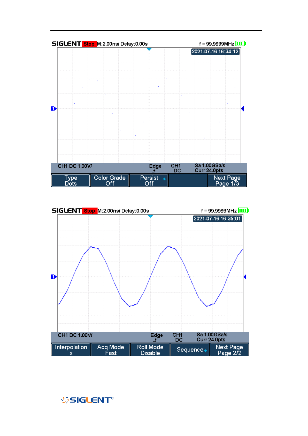
SHS800X&SHS1000X User Manual
WWW.SIGLENT.COM
Figure 15 Display Type Set to Dots
Figure 16 x Interpolation
42
Page 64
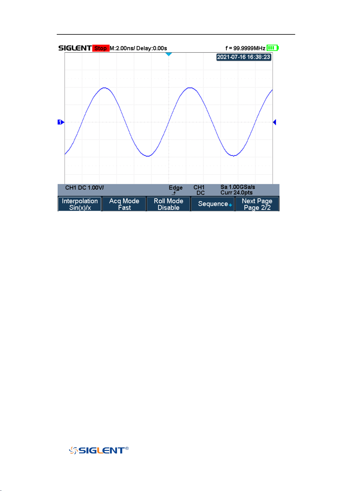
SHS800X&SHS1000X User Manual
WWW.SIGLENT.COM
Figure 17 Sinx/x Interpolation
43
Page 65
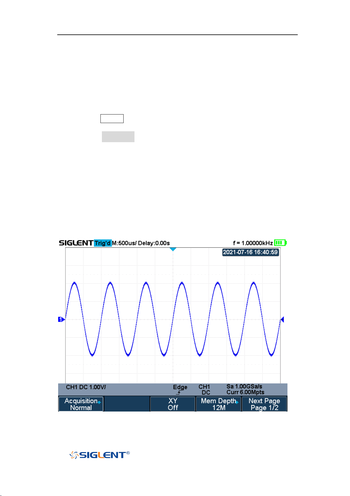
SHS800X&SHS1000X User Manual
WWW.SIGLENT.COM
Acquisition Mode
The acquisition mode is used to control how to generate waveform points from
sample points. The oscilloscope provides the following acquisition mode: Normal,
Peak Detect, Average, and ERES.
1. Press the Acquire button on the front panel to enter the ACQUIRE function
menu;
2. Press the Acquisition softkey; then turn the Universal Knob to select the
desired acquisition mode and push down the knob to confirm. The default
setup is Normal.
Normal
In this mode, the oscilloscope samples the signal at equal time intervals to
rebuild the waveform. For most of the waveforms, the best display effect can be
obtained using this mode. It is the default acquisition mode.
Figure 18 Acquisition System
44
Page 66
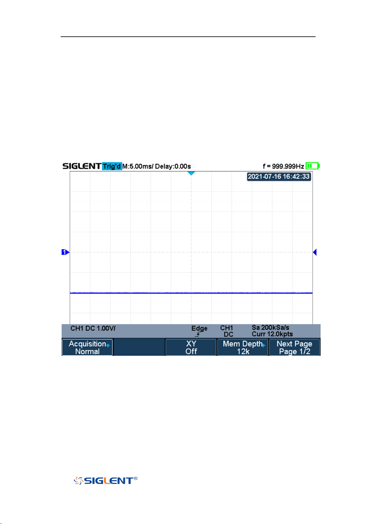
SHS800X&SHS1000X User Manual
WWW.SIGLENT.COM
Peak Detect
In this mode, the oscilloscope acquires the maximum and minimum values of the
signal within the sample interval to get the signal's envelope or the narrow pulse
of the signal that might be lost. In this mode, signal confusion can be prevented
but the noise displayed would be larger.
In this mode, the oscilloscope can display all the pulses with pulse widths at least
as wide as the sample period.
Figure 19 Pulse With 0.1% Duty, Normal Mode
45
Page 67
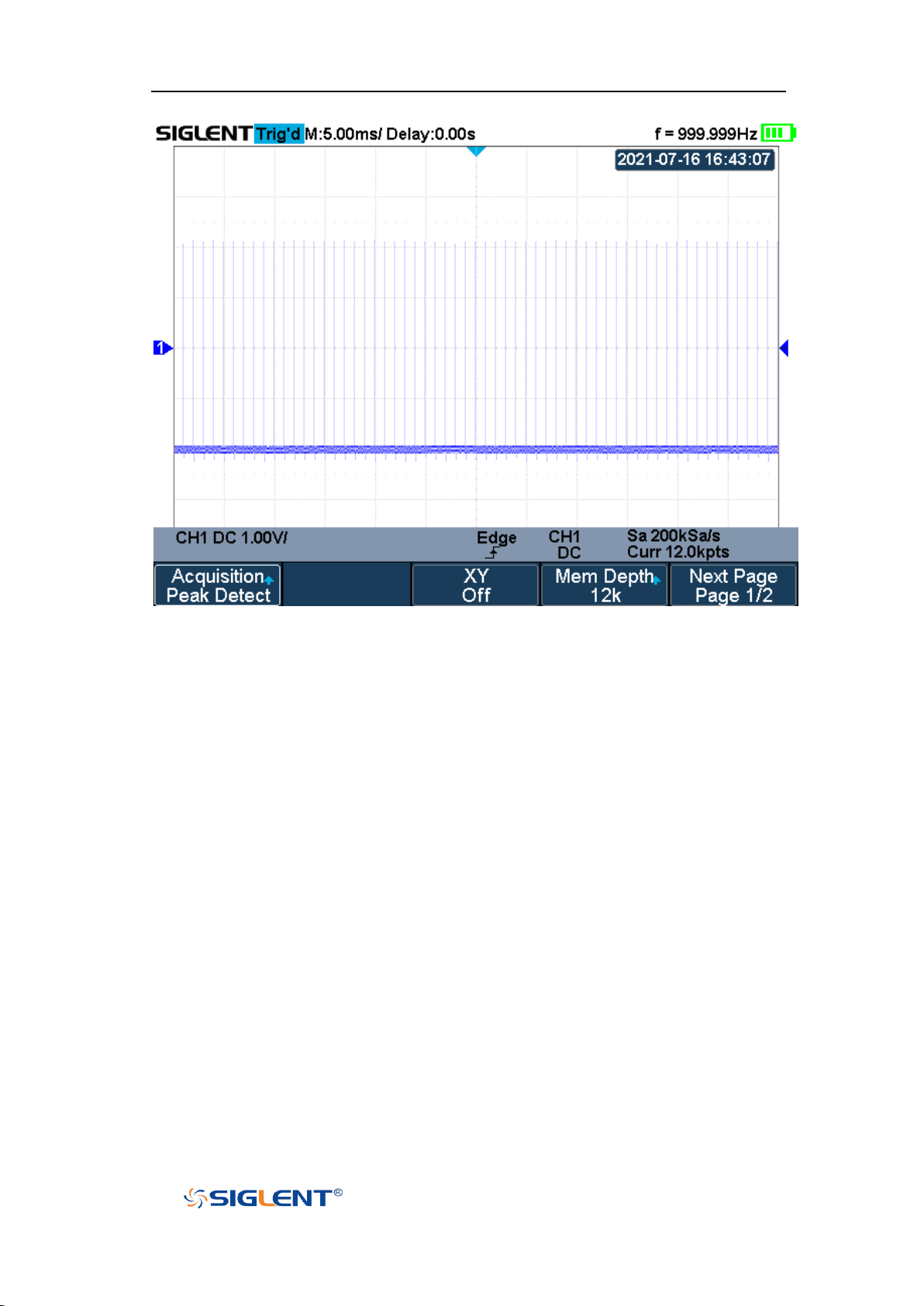
SHS800X&SHS1000X User Manual
WWW.SIGLENT.COM
Figure 20 Pulse With 0.1% Duty, Peak Detect Mode
Average
In this mode, the oscilloscope averages the waveforms from multiple samples to
reduce the random noise of the input signal and improve the vertical resolution.
The greater the number of averages is, the lower the noise and the higher the
vertical resolution will be. Still, the slower the response of the displayed
waveform to the waveform changes will be.
The available range of averages is from 4 to 1024 and the default is 16. When
Average mode is selected, press Averages and turn the Universal knob or press
the softkey continually to set the desired average time.
46
Page 68
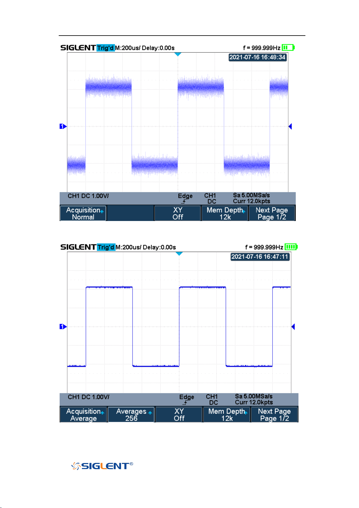
SHS800X&SHS1000X User Manual
WWW.SIGLENT.COM
Figure 21 With Random Noise, Normal Mode
Figure 22 With Random Noise, Average Mode
47
Page 69

SHS800X&SHS1000X User Manual
WWW.SIGLENT.COM
Note: “Average” and “ERES” mode use different averaging methods. The
former uses “Waveform Average” and the latter uses “Dot Average”.
ERES
This mode uses a kind of ultra-sample technique to average the neighboring
points of the sample waveform to reduce the random noise on the input signal
and generate much smoother waveforms on the screen. ERES mode is generally
used when the sample rate of the digital converter is higher than the storage rate
of the acquisition memory.
ERES mode can be used on single-shot and repetitive signals and does not slow
waveform updates. This mode limits the oscilloscope's real- time bandwidth
because it effectively acts like a low- pass filter.
48
Page 70
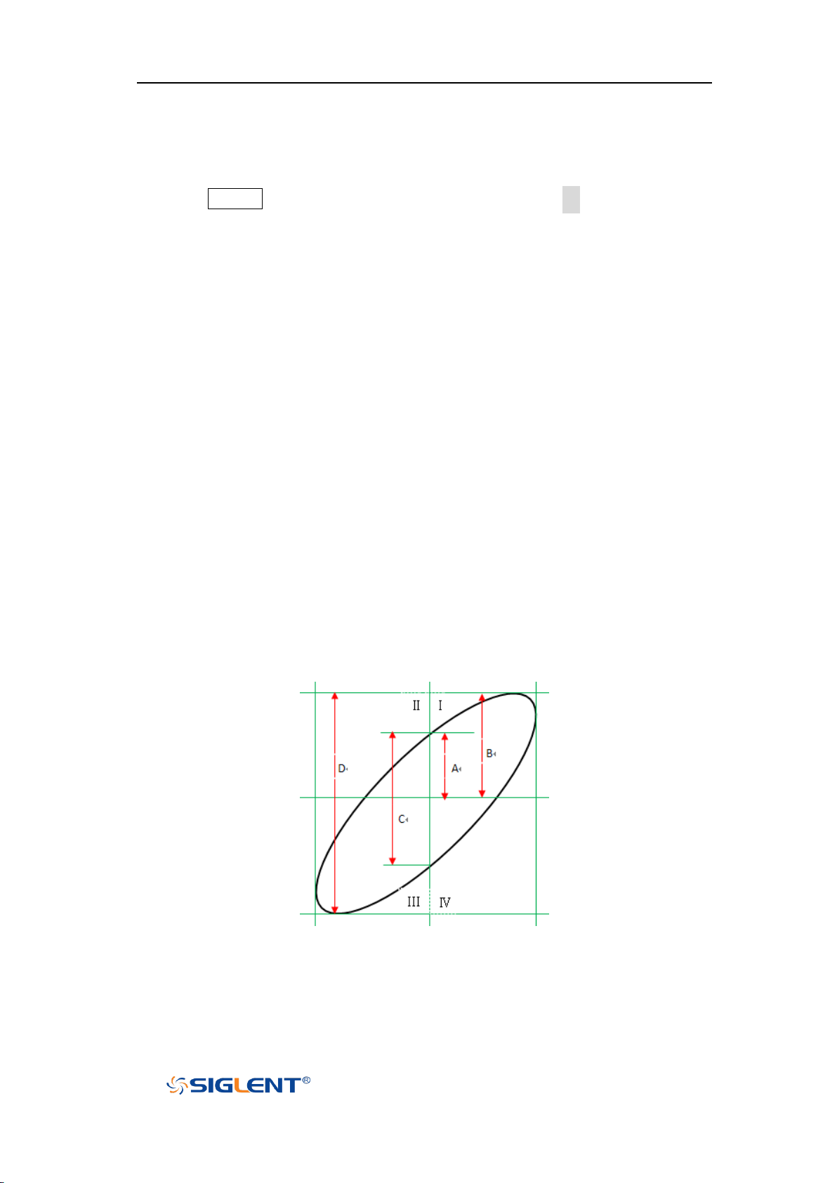
SHS800X&SHS1000X User Manual
WWW.SIGLENT.COM
Horizontal Format
Press the Acquire button on the front panel; then press the XY soft key to set the
XY(On) or YT(Off) mode. The default setup is YT.
YT
It is the normal viewing mode for the oscilloscope. In the Normal time mode,
signal events occurring before the trigger are plotted to the left of the trigger
point and signal events after the trigger plotted to the right of the trigger point.
XY
XY mode changes the display from a volt- versus- time display to a volt- versusvolt display. Channel 1 amplitude is plotted on the X- axis and Channel 2
amplitude is plotted on the Y- axis, the two channels will be turned on or off
together.
You can use XY mode to compare frequency and phase relationships between
two signals. XY mode can also be used with transducers to display strain versus
displacement, flow versus pressure, volts versus current, or voltage versus
frequency.
The phase deviation between two signals with the same frequency can be easily
measured via Lissajous method. The figure below shows the measurement
schematic diagram of the phase deviation
According to sinθ=A/B or C/D (wherein, θ is the phase deviation angle between
the two channels and the definitions of A, B, C, and D are as shown in the figure
above), the phase deviation angle is obtained, that is: θ=±arcsin (A/B) or ±arcsin
(C/D)
49
Page 71

SHS800X&SHS1000X User Manual
WWW.SIGLENT.COM
If the principal axis of the ellipse is within quadrant I and III, the phase deviation
angle obtained should be within quadrants I and IV, namely within (0 to π/2) or
(3π/2 to 2π). Suppose the principal axis of the ellipse is within quadrant II and IV.
In that case, the phase deviation angle obtained should be within quadrant II and
III, namely within (π/2 to π) or (π to 3π/2).
The X-Y function can be used to measure the phase deviation that occurred when
the signal under test passes through a circuit network. Connect the oscilloscope
to the circuit to monitor the input and output signals of the circuit.
50
Page 72
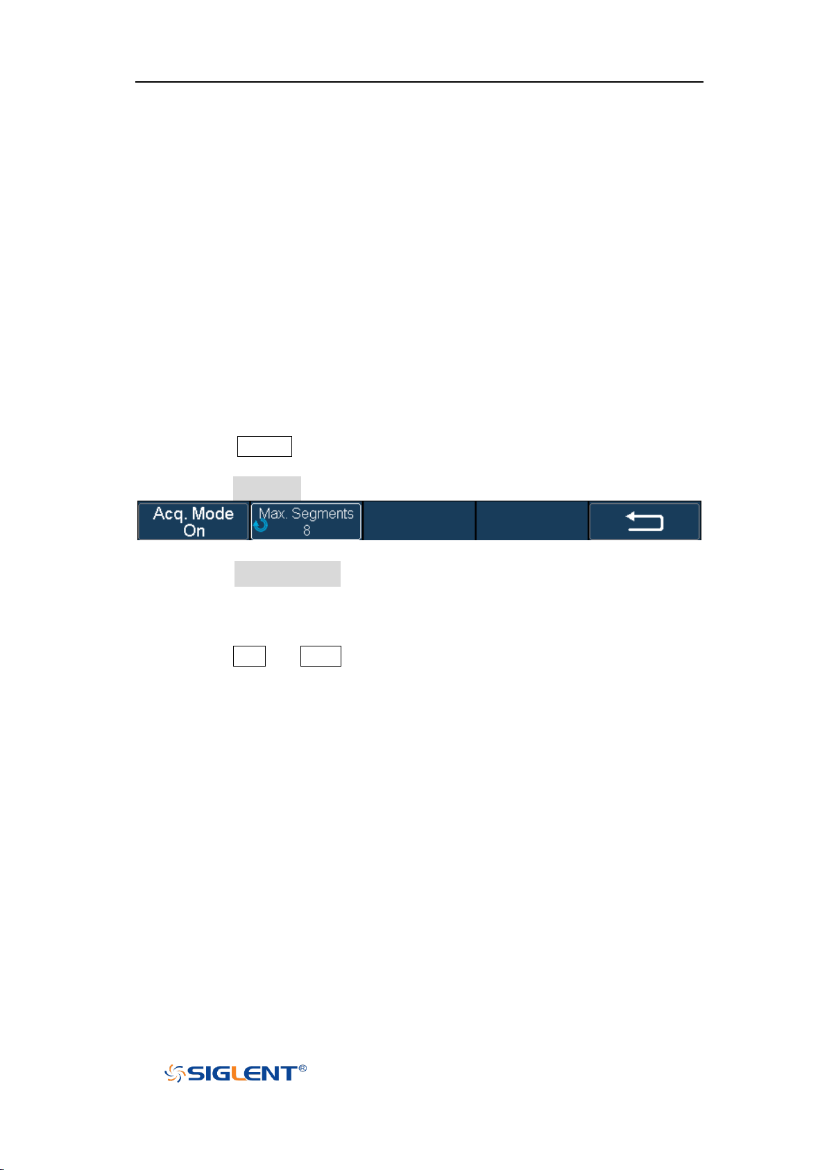
SHS800X&SHS1000X User Manual
WWW.SIGLENT.COM
Sequence Mode
Sequence is also a kind of acquisition mode, which does not display waveform
during the sampling process. It improves the waveform capture rate, and the
maximal capture rate is 400,000 wfs/s. So it can capture the small probability
event effectively.
The oscilloscope runs and fills a memory segment for each trigger event. The
oscilloscope is busy acquiring multiple segments. The oscilloscope continues to
trigger until memory is filled, and then display the waveforms on the screen.
To use the sequence mode, the HORIZONTAL Format must be set to YT.
Do the following steps to use the sequence mode.
1. Press the Acquire button on the front panel to enter the ACQUIRE function
menu;
2. Press the Sequence softkey to enter the SEQUENCE function menu.
Figure 23 SEQUENCE Function Menu
3. Press the Max. Segments softkey; and then turn the Universal Knob to select
the desired value.
Do the following steps to replay the sequence waveform under history mode:
1. Press the Shift and Meter button to enable HISTORY function.
51
Page 73
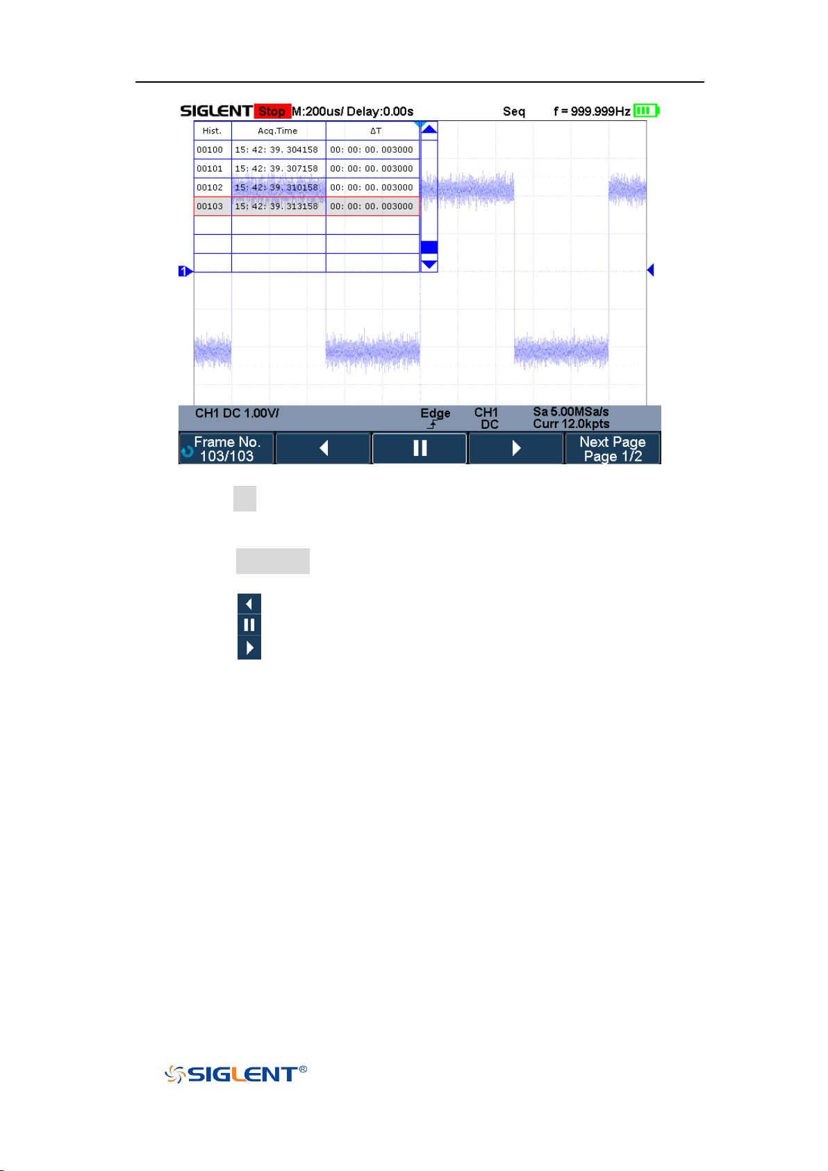
SHS800X&SHS1000X User Manual
WWW.SIGLENT.COM
Figure 24 HISTORY Function Menu
2. Press the List softkey to turn on the list display. The list records the acquisition
time of every frame and shows the frame number that displaying on the
screen.
3. Press the Frame No. softkey; and then turn the Universal Knob to select the
frame to display.
4. Press the softkey to replay the waveform from the current frame to 1.
5. Press the softkey to stop replay.
6. Press the softkey to replay the waveform from the current frame to the
last frame.
52
Page 74
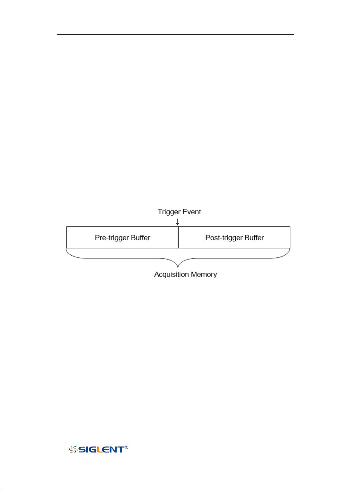
SHS800X&SHS1000X User Manual
WWW.SIGLENT.COM
Trigger
For trigger, you set certain trigger condition according to the requirement. When
a waveform in the waveform stream meets this condition, the oscilloscope
captures this waveform and the neighboring part and displays them on the
screen. Still, the digital oscilloscope displays waveform continuously no matter
whether it is stably triggered, but only stable trigger can ensure stable display.
The trigger circuit ensures that every time base sweep or acquisition starts from
the input signal and the user-defined trigger condition. Every sweep is
synchronous to the acquisition and the waveforms acquired overlap to display
stable waveform.
The following is the schematic diagram of the acquisition memory. As shown in
the figure below, the position of the trigger event is determined by the reference
time point and the delay setting.
Trigger setting should be based on the features of the input signal, thus you need
to have some knowledge of the signal under test to quickly capture the desired
waveform.
The oscilloscope provides abundant advanced trigger functions which can help
you to focus on the desired waveform details. These trigger types are edge, slope,
pulse, video, window, interval, dropout, runt, pattern and serial trigger. This
chapter will mainly introduce all these trigger functions mentioned above in
detail and tell you how to set the trigger conditions to capture the desired
waveform.
53
Page 75

SHS800X&SHS1000X User Manual
WWW.SIGLENT.COM
The contents of this chapter:
Trigger Source
Trigger Mode
Trigger Level
Trigger Coupling
Trigger Holdoff
Noise Rejection
Trigger Type
54
Page 76
SHS800X&SHS1000X User Manual
WWW.SIGLENT.COM
Note: to select stable channel waveform as the trigger source to stabilize the
display.
Trigger Source
Press the Trigger Setup button on the front panel to enter the TRIGGER function
menu; press the Source softkey and then turn the Universal Knob to select the
desired trigger source.
The current trigger source is displayed at the bottom of the screen. Select channel
with signal input as trigger source to obtain stable trigger.
Analog channel input:
Signals input from analog channels can all be used as the trigger source.
55
Page 77

SHS800X&SHS1000X User Manual
WWW.SIGLENT.COM
Trigger Mode
The SHS800X/SHS1000X’s trigger mode includes auto, normal, single and Force.
Trigger mode affects how the oscilloscope searches for the trigger
After the oscilloscope starts running, the oscilloscope operates by first filling the
pre-trigger buffer. It starts searching for a trigger after the pre-trigger buffer is
filled and continues to flow data through this buffer while it searches for the
trigger. While searching for the trigger, the oscilloscope overflows the pre-trigger
buffer and the first data put into the buffer is first pushed out (First Input First Out,
FIFO).
When a trigger is found, the pre- trigger buffer contains the events that occurred
before the trigger. Then, the oscilloscope fills the post- trigger buffer and
displays the acquisition memory.
Press the Trigger Setup button and Mode softkey to select the desired trigger
mode.
In the Auto trigger mode (the default setting), if the specified trigger
conditions are not found, triggers are forced and acquisitions are made so
hat signal activity is displayed on the oscilloscope.
The Auto trigger mode is appropriate when:
Checking DC signals or signals with unknown levels or activity.
When trigger conditions occur often enough that forced triggers are
unnecessary.
In the Normal trigger mode, triggers and acquisitions only occur when the
specified trigger conditions are found. Otherwise, the oscilloscope holds the
original waveform and waits for the next trigger.
The Normal trigger mode is appropriate when:
You only want to acquire specific events specified by the trigger settings.
Triggering on an infrequent signal from a serial bus (for example, I2C,
SPI, CAN, LIN, etc.) or another signal that arrives in bursts. The Normal
trigger mode lets you stabilize the display by preventing the oscilloscope
from auto- triggering.
In the Single trigger mode, the oscilloscope waits for a trigger, displays the
waveform when the trigger condition is met, and stops.
The Single trigger mode is appropriate when:
56
Page 78

SHS800X&SHS1000X User Manual
WWW.SIGLENT.COM
To capture single event or a periodic signal.
To capture burst or other unusual signals.
In the Force trigger mode, when the trigger condition is not met, it will be
force triggered after the frame is acquired. The trigger status in the upper left
corner of the screen will be displayed as "FStop".
57
Page 79
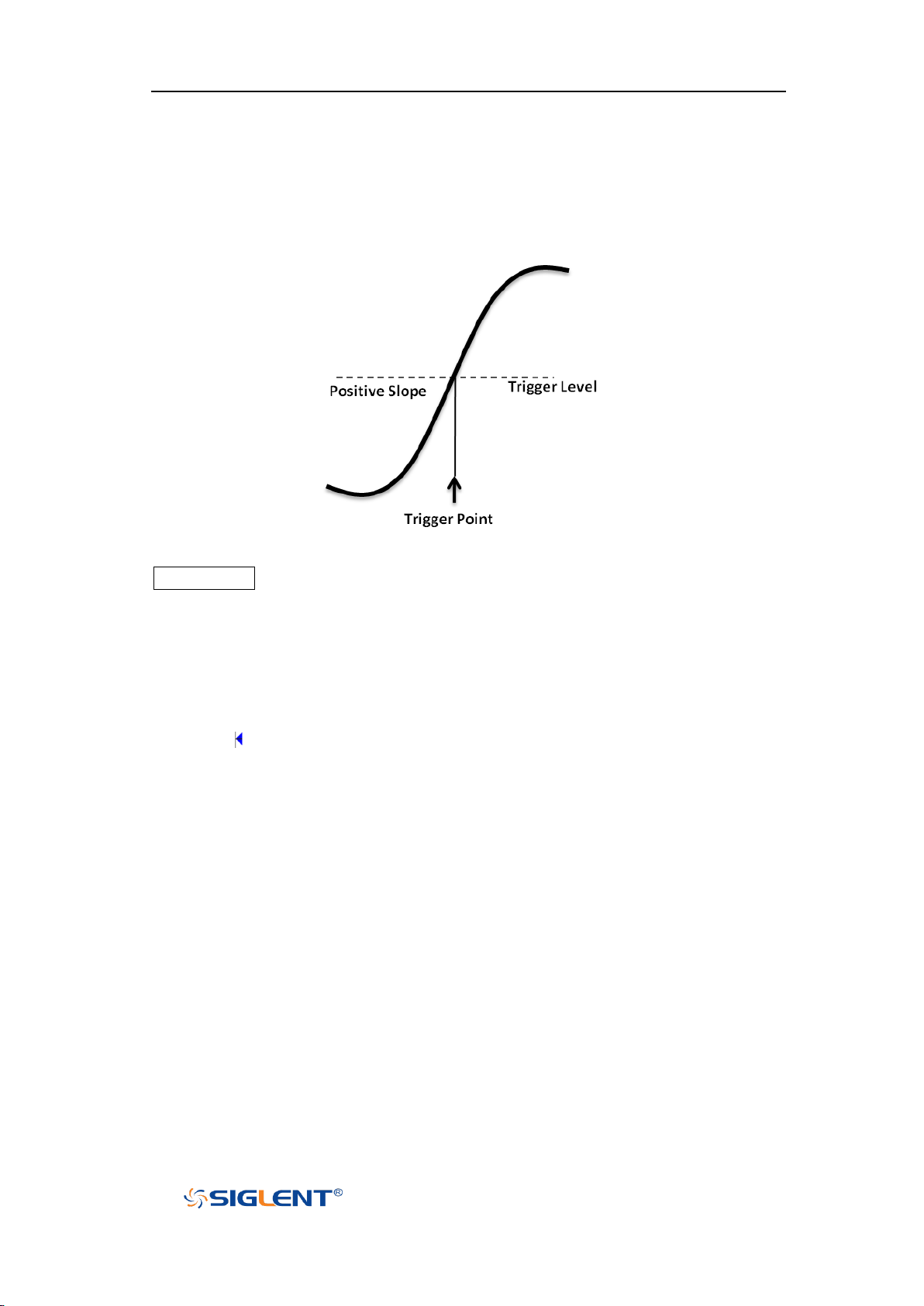
SHS800X&SHS1000X User Manual
WWW.SIGLENT.COM
Trigger Level
Trigger level and slope define the trigger point,
You can adjust the trigger level for a selected analog channel by pressing the
Trigger Level button and turning the Universal Knob.
You can push the Universal Knob to set the level to the waveform's 50% value
immediately. If AC coupling is used, pushing the Universal Knob sets the trigger
level to about 0 V.
The position of the trigger level for the analog channel is indicated by the trigger
level icon (if the analog channel is on) at the left side of the display.
58
Page 80
SHS800X&SHS1000X User Manual
WWW.SIGLENT.COM
Note: trigger coupling has nothing to do with the channel coupling.
Trigger Coupling
Press the Trigger Setup button on the front panel to enter the TRIGGER function
menu. Then, press the Coupling softkey and turn the Universal Knob or press the
Coupling softkey continually to select the desired coupling mode.
The oscilloscope provides 4 kinds of trigger coupling modes:
DC: allow DC and AC components into the trigger path.
AC: block all the DC components and attenuate signals lower than 8 Hz. Use
AC coupling to get a stable edge trigger when your waveform has a large DC
offset.
LF Reject: block the DC components and reject the low frequency
components lower than 2 MHz. Low frequency reject removes unwanted low
frequency components from a trigger waveform, such as power line
frequencies, etc. that can interfere with proper triggering. Use LF Reject
coupling to get a stable edge trigger when your waveform has low frequency
noise.
HF Reject: reject the high frequency components higher 1.2 MHz)
59
Page 81
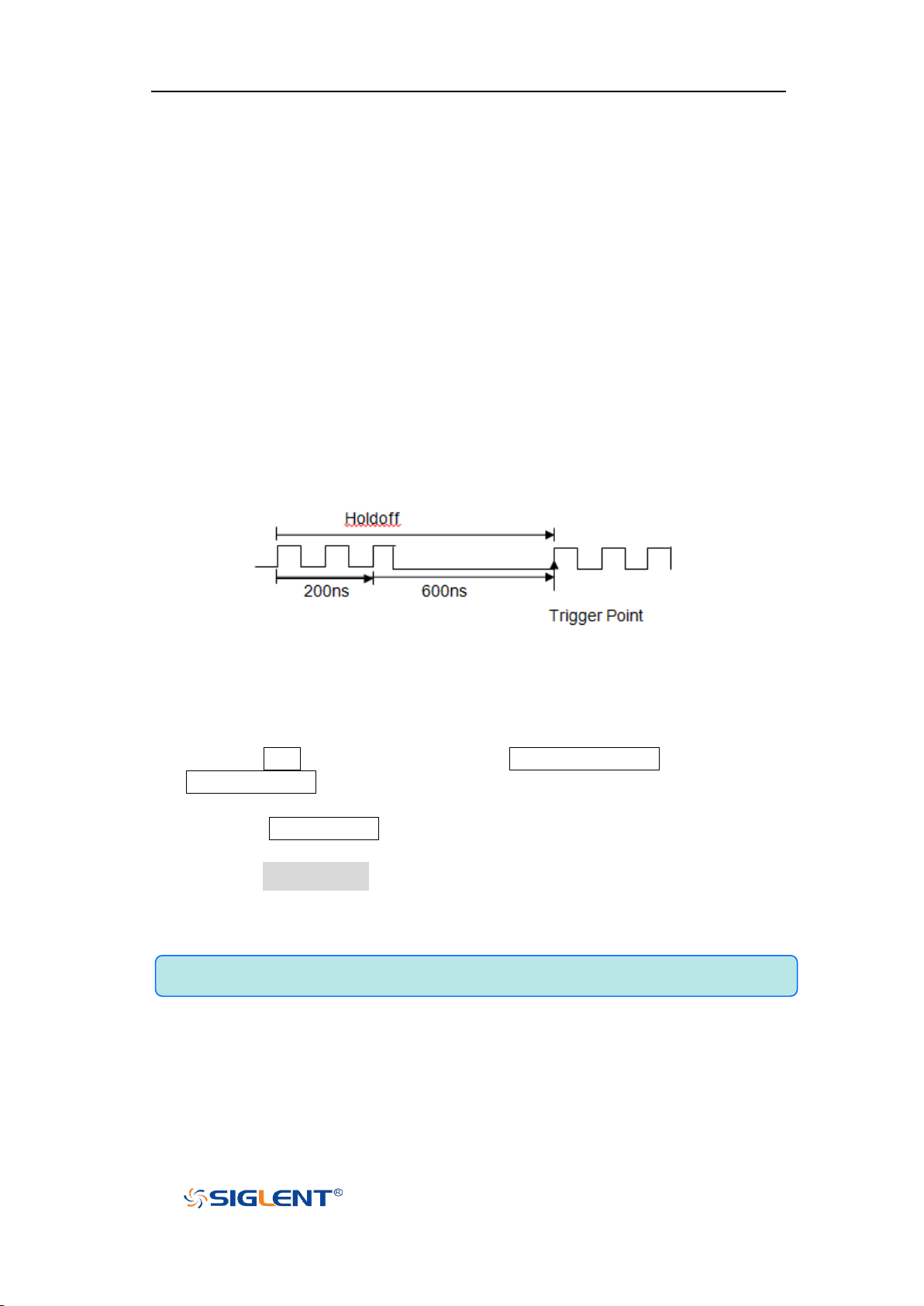
SHS800X&SHS1000X User Manual
WWW.SIGLENT.COM
Note: adjust the time scale and horizontal position will not affect the holdoff
Trigger Holdoff
Trigger holdoff can be used to stably trigger the complex waveforms (such as
pulse series). Holdoff time is the amount of time that the oscilloscope waits
before re-arming the trigger circuitry. The oscilloscope will not trigger until the
holdoff time expires.
Use the holdoff to trigger repetitive waveforms with multiple edges (or other
events) between waveform repetitions. You can also use holdoff to trigger on the
first edge of a burst when you know the minimum time between bursts.
For example, to get a stable trigger on the repetitive pulse burst below, set the
holdoff time to be >200 ns but <600 ns.
The correct holdoff setting is typically slightly less than one repetition of the
waveform. Set the holdoff to this time to generate a unique trigger point for a
repetitive waveform. Only edge trigger and serial trigger have holdoff option.
The holdoff time of the oscilloscope is adjustable from 80ns to 1.5s.
1. Press the Stop button, and then use the Horizontal Position button and the
Horizontal Scale button to find where the waveform repeats. Measure this
time using cursors; then, set the holdoff.
2. Press the Trigger Setup button to enter the TRIGGER function menu. The
default trigger type is edge.
3. Press the Holdoff Close softkey; and then turn the Universal Knob to set the
desired holdoff time.
60
Page 82
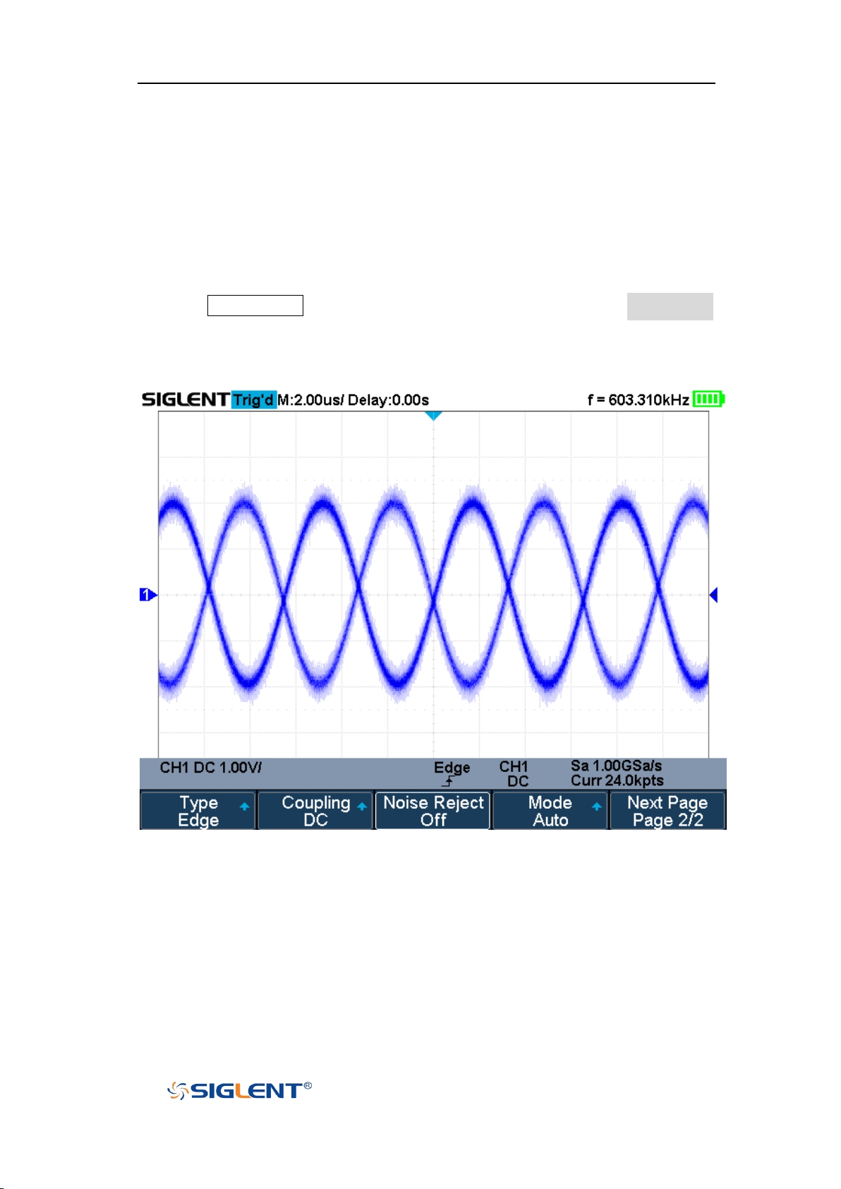
SHS800X&SHS1000X User Manual
WWW.SIGLENT.COM
Noise Rejection
Noise Reject adds additional hysteresis to the trigger circuitry. By increasing the
trigger hysteresis band, you reduce the possibility of triggering on noise.
However, this also decreases the trigger sensitivity so that a slightly larger signal
is required to trigger the oscilloscope.
Press the Trigger Setup button on the front panel, and then press the Noise Reject
softkey continually to set the option to On or Off to turn on or off the noise
rejection function.
Figure 25 Turn off the Noise Reject
61
Page 83
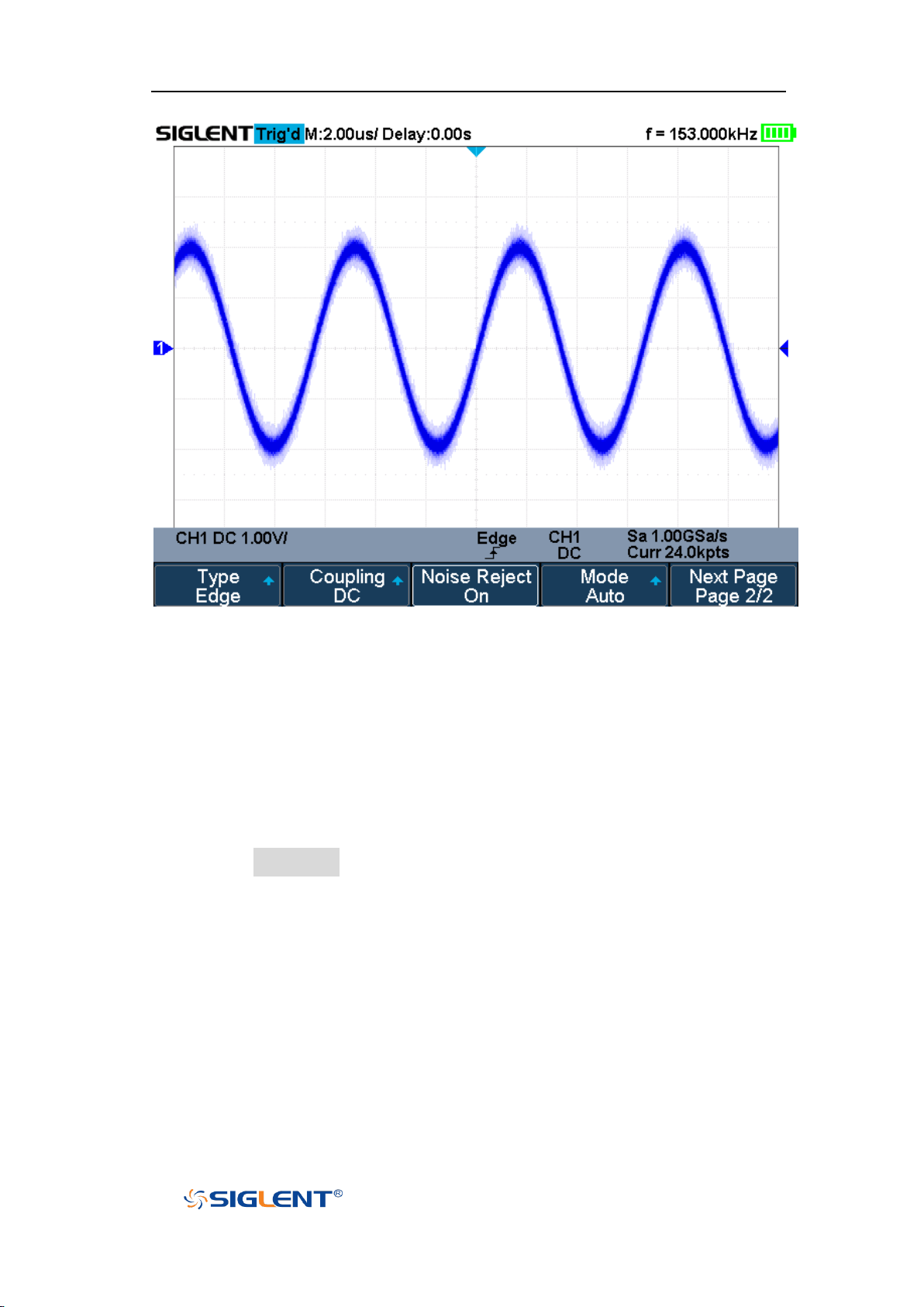
SHS800X&SHS1000X User Manual
WWW.SIGLENT.COM
Figure 26 Turn on the Noise Reject
If the signal you are probing is noisy, you can set up the oscilloscope to reduce
the noise in the trigger path and on the displayed waveform. First, stabilize the
displayed waveform by removing the noise from the trigger path. Second, reduce
the noise on the displayed waveform.
1. Connect a signal to the oscilloscope and obtain a stable display.
2. Remove the noise from the trigger path by setting trigger coupling to LF
Reject, HF Reject or turning on Noise Reject.
3. Set the Acquisition option to Average to reduce noise on the displayed
waveform.
62
Page 84

SHS800X&SHS1000X User Manual
WWW.SIGLENT.COM
Trigger Type
The oscilloscope provides abundant advanced trigger functions, including
various serial bus triggers.
Edge trigger
Slope trigger
Pulse trigger
Video trigger
Window trigger
Interval trigger
Dropout trigger
Runt trigger
Pattern trigger
63
Page 85
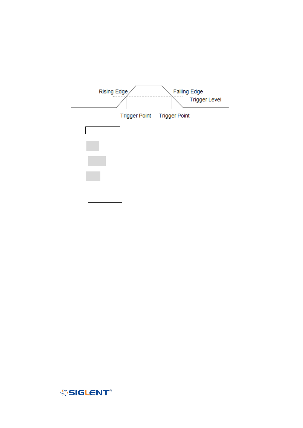
SHS800X&SHS1000X User Manual
WWW.SIGLENT.COM
Edge Trigger
Edge trigger distinguishes the trigger points by seeking the specified edge (rising,
falling, alternating) and trigger level.
1. Press the Trigger Setup button on the front panel to enter the TRIGGER system
function menu.
2. Press the Type softkey; turn the Universal Knob to set select Edge and then
push the knob to confirm.
3. Press the Source softkey; turn the Universal Knob to select the deserted
trigger source.
4. Press the Slope softkey; turn the Universal Knob to select the desired trigger
edge (rising, falling or alternating), and then press down the knob to confirm.
The current trigger slope is displayed at the bottom of the screen.
5. Press the Trigger Level button and turn the Universal Knob to adjust the
trigger level to obtain stable trigger.
64
Page 86
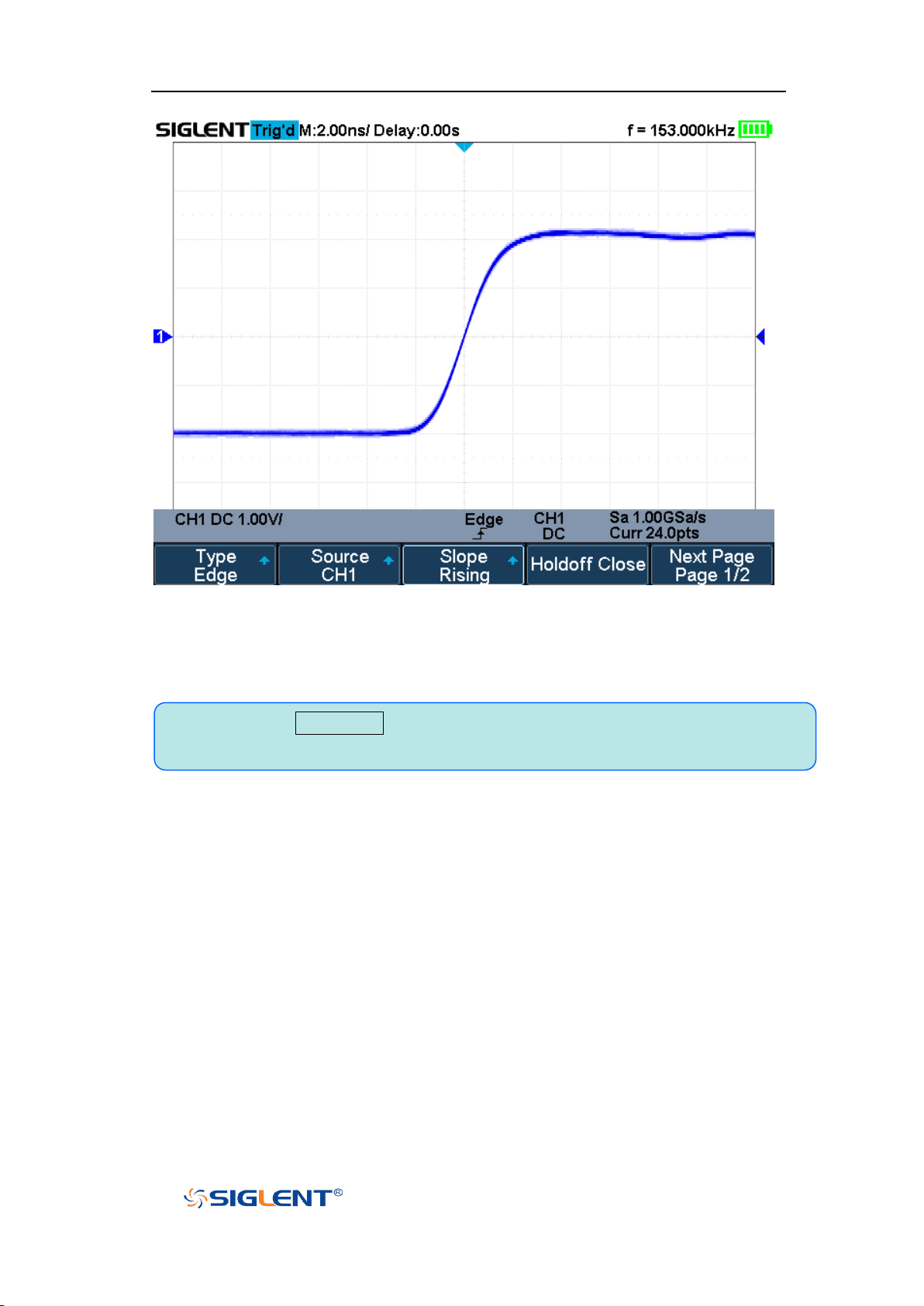
SHS800X&SHS1000X User Manual
WWW.SIGLENT.COM
Note: Press the Auto Setup button will set the trigger type to Edge and slope to
rising.
Figure 27 Edge Trigger
Holdoff, coupling and noise reject can be set in edge trigger, see the sections
“Trigger Holdoff”, "Trigger Coupling" and "Noise Rejection" for details.
65
Page 87
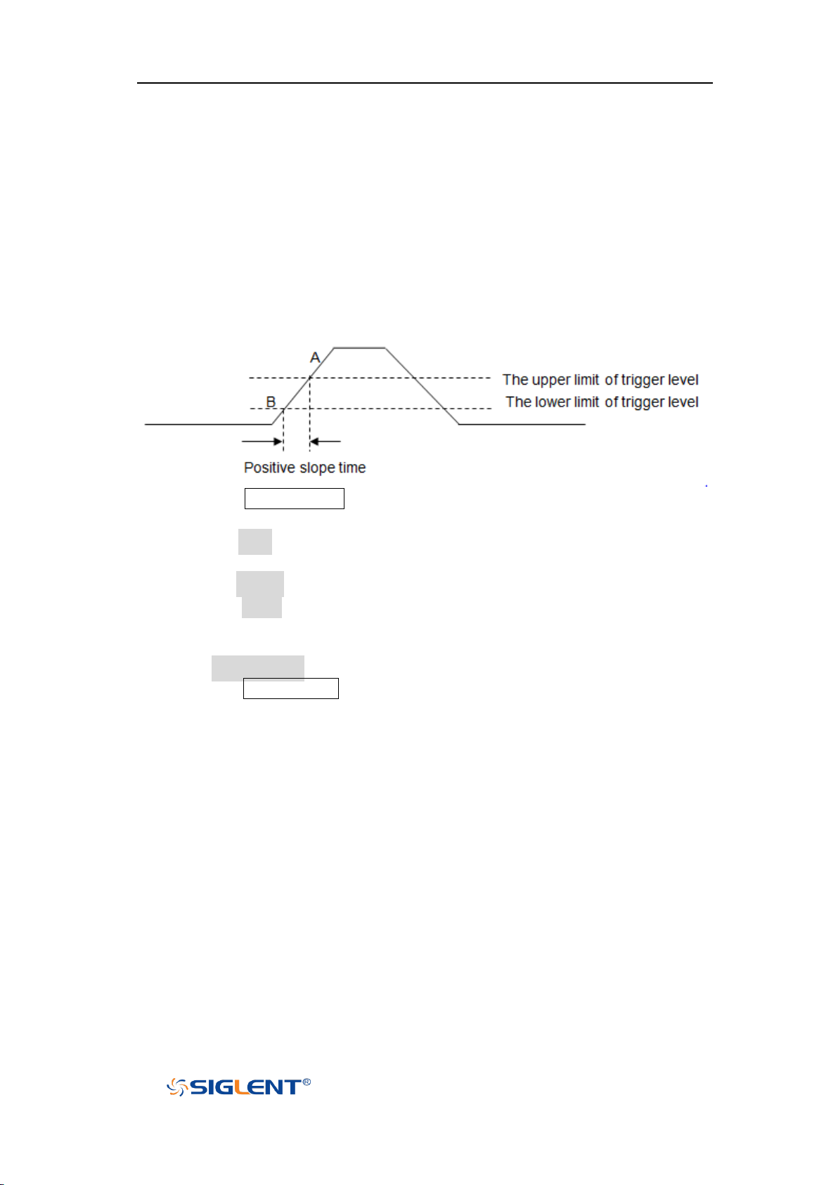
SHS800X&SHS1000X User Manual
WWW.SIGLENT.COM
Slope Trigger
The slope trigger looks for a rising or falling transition from one level to another
level in greater than or less than a certain amount of time.
In the oscilloscope, positive slope time is defined as the time difference between
the two crossing points of trigger level line A and B with the positive edge as
shown in the figure below.
1. Press the Trigger Setup button on the front panel to enter the TRIGGER
function menu.
2. Press the Type softkey; turn the Universal Knob to set select Slope and then
push the knob to confirm.
3. Press the Source softkey; turn the Universal Knob to select the trigger source.
4. Press the Slope softkey; turn the Universal Knob to set select the desired
trigger edge (rising or falling), and then push down the knob to confirm. The
current trigger slope is displayed at the upper right corner of the screen.
5. Press Lower Upper softkey to select the Lower or Upper trigger level; then
press the Trigger Level button and turn the Universal Knob to adjust the
position.
The lower trigger level cannot be upper than the upper trigger level.
66
Page 88
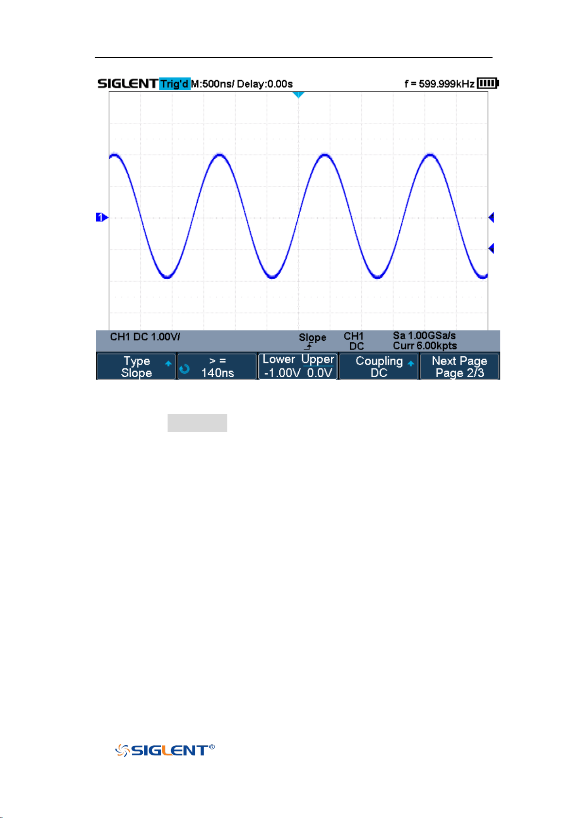
SHS800X&SHS1000X User Manual
WWW.SIGLENT.COM
Figure 28 Slope Trigger
6. Press the Limit Range softkey; then turn the Universal Knob to select the
desired slope condition, and push down the knob to confirm.
<= (less than a time value): trigger when the input signal's positive or
negative slope time is lower than the specified time value.
>= (greater than a time value): trigger when the input signal's positive or
negative slope time is greater than the specified time value.
[--,--] (within a range of time value):trigger when the input signal's
positive or negative slope time is greater than the specified lower limit of
time and lower than the specified upper limit of time value.
--][-- (outside a range of time value): trigger when the input signal's
positive or negative slope time is greater than the specified upper limit of
time and lower than the specified lower limit of time value.
Coupling and noise reject can be set in slope trigger, see the sections "Trigger
Coupling" and "Noise Rejection" for details.
67
Page 89
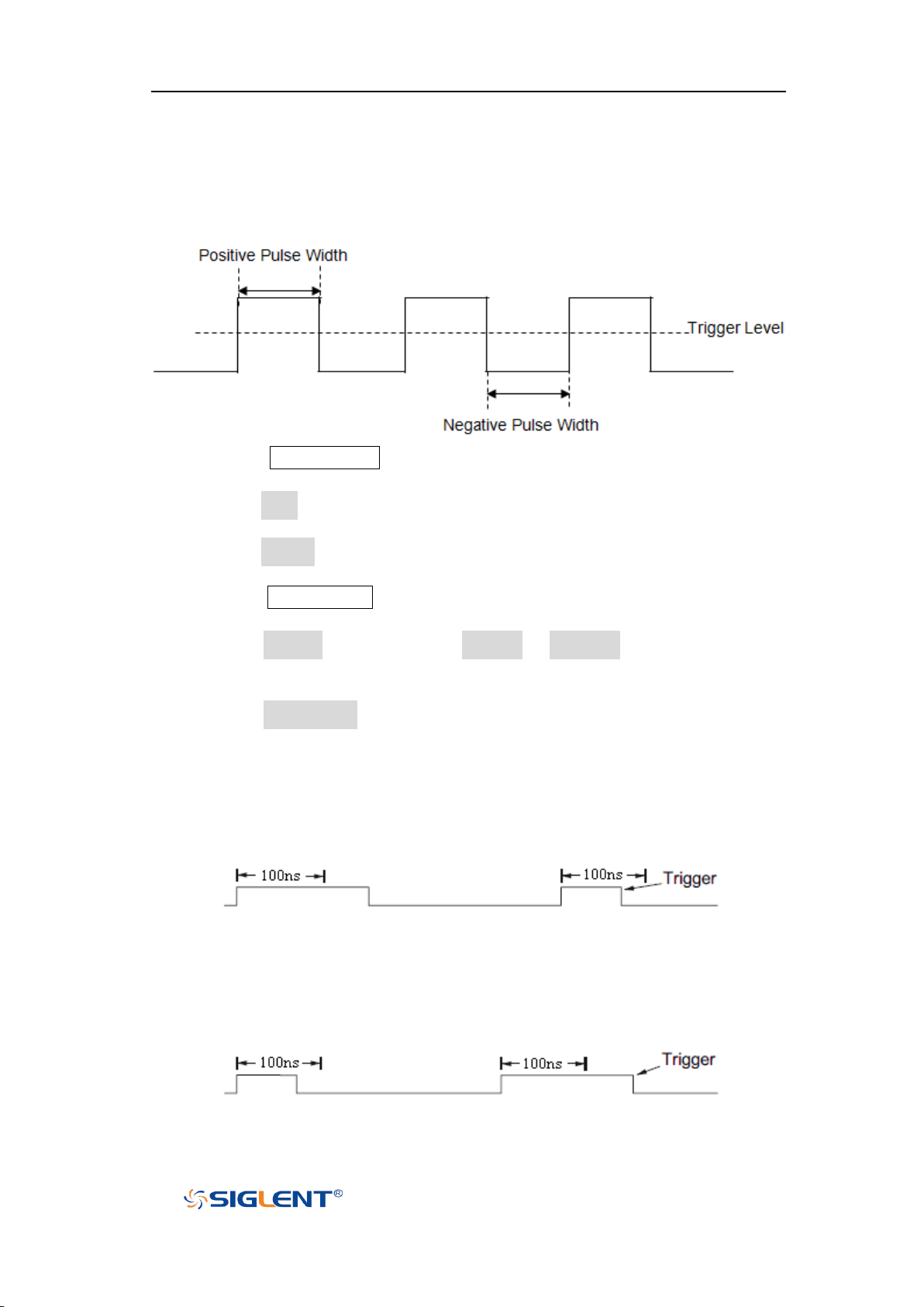
SHS800X&SHS1000X User Manual
WWW.SIGLENT.COM
Pulse Trigger
Trigger on the positive or negative pulse with a specified width.
1. Press the Trigger Setup button on the front panel to enter the TRIGGER
function menu.
2. Press the Type softkey; turn the Universal Knob to select Pulse and then push
the knob to confirm.
3. Press the Source softkey; turn the Universal Knob to select CH1 or CH2 as the
trigger source.
4. Press the Trigger Level button and turn the Universal Knob to adjust the
trigger level to the desired place.
5. Press the Polarity softkey to select Positive or Negative pulse that to trigger
on. The current trigger polarity is displayed at the upper right corner of the
screen.
6. Press the Limit Range softkey; turn the Universal Knob to select the desired
condition.
<= (less than a time value): trigger when the input signal's positive or
negative pulse time is lower than the specified time value.
For example, for a positive pulse, if you set t (pulse real width) ≤ 100ns,
the waveform will trigger.
>= (greater than a time value): trigger when the input signal's positive or
negative pulse time is greater than the specified time value.
For example, for a positive pulse, if you set t (pulse real width) ≥ 100ns,
the waveform will trigger.
68
Page 90
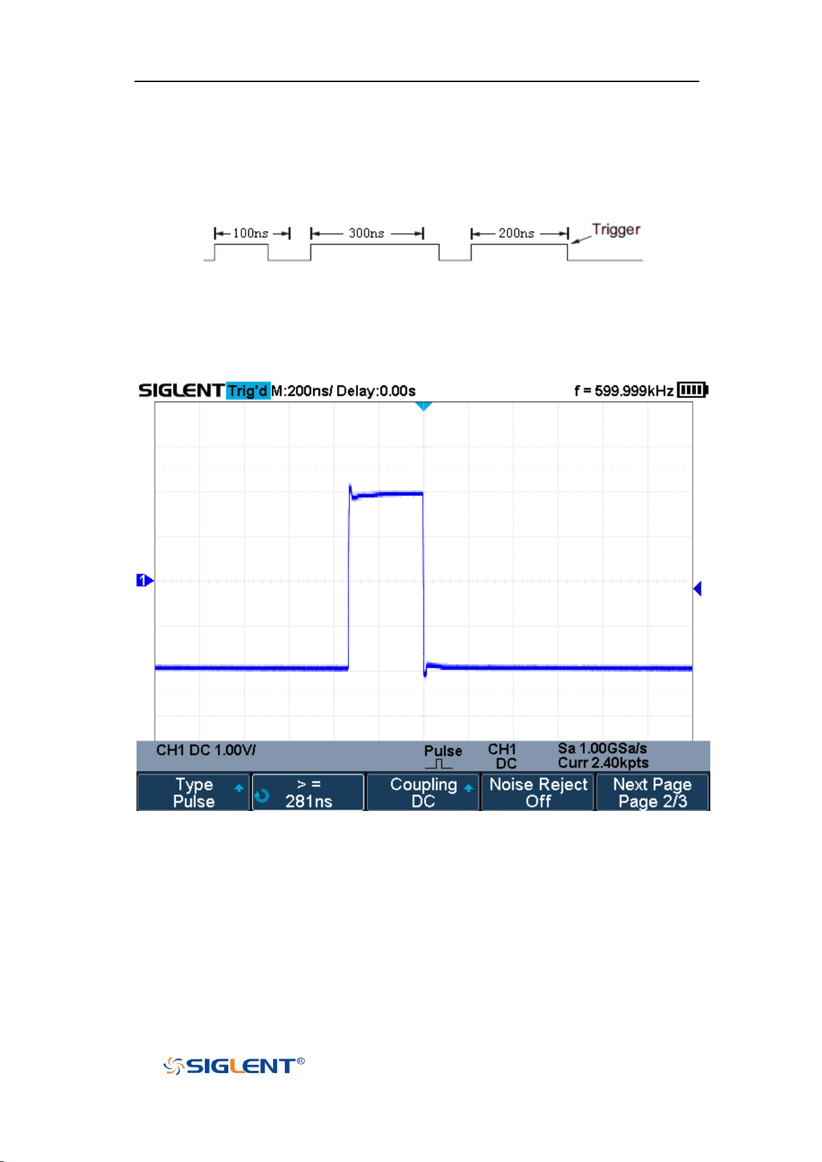
SHS800X&SHS1000X User Manual
WWW.SIGLENT.COM
[--,--] (within a range of time value):trigger when the input signal's
positive or negative pulse time is greater than the specified lower limit of
time and lower than the specified upper limit of time value.
For example, for a positive pulse, if you set t (pulse real width) ≥100ns
and t ≤ 300ns, the waveform will trigger.
--][-- (outside a range of time value): trigger when the input signal's
positive or negative pulse time is greater than the specified upper limit of
time and lower than the specified lower limit of time value.
Coupling and noise reject can be set in pulse trigger, see the sections "Trigger
Coupling" and "Noise Rejection" for details.
Figure 29 Pulse Trigger
69
Page 91
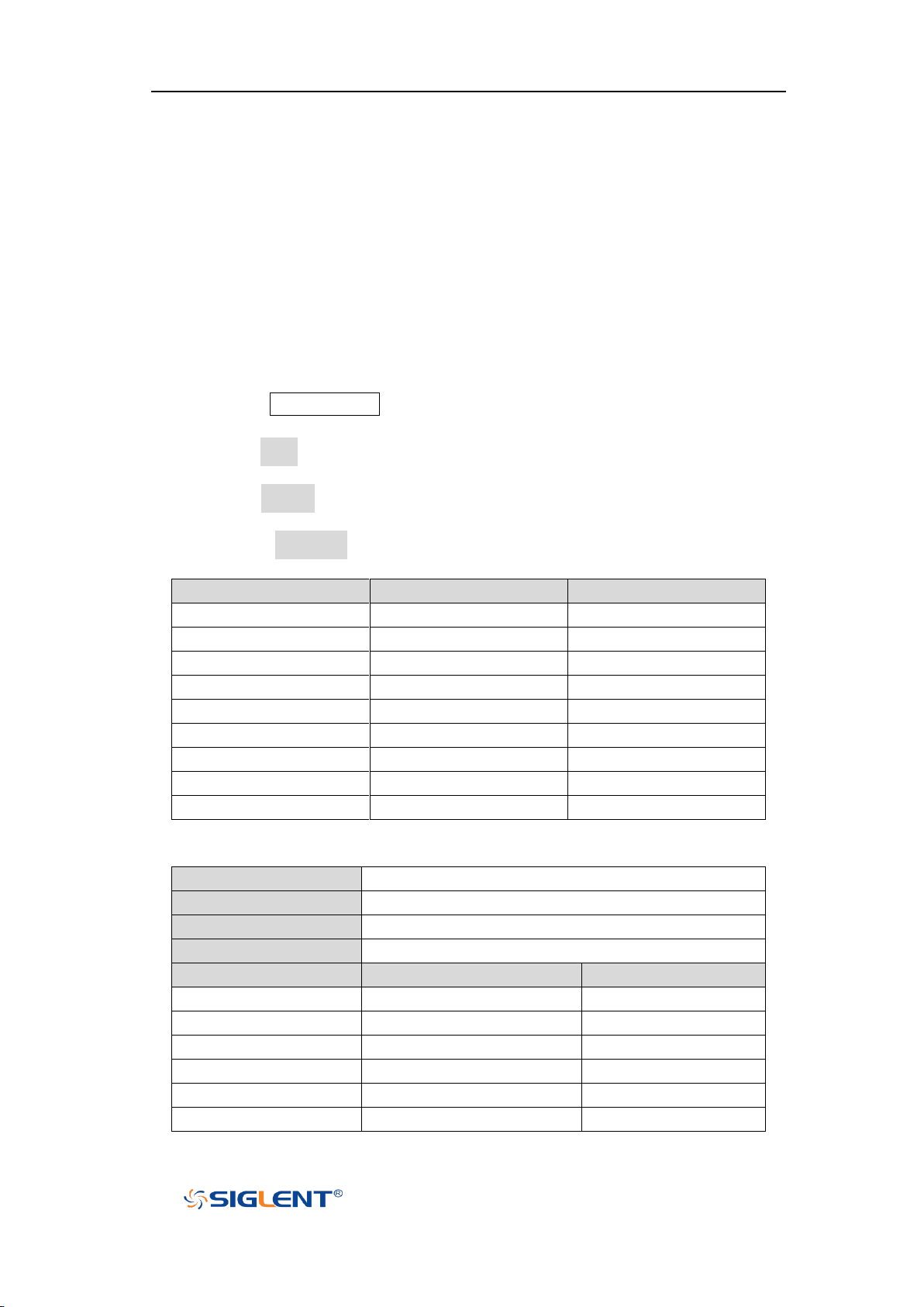
SHS800X&SHS1000X User Manual
WWW.SIGLENT.COM
Standard
Type
Sync Pulse
NTSC
Interlaced
BI-level
PAL
Interlaced
BI-level
HDTV 720P/50
Progressive
Tri-level
HDTV 720P/60
Progressive
Tri-level
HDTV 1080P/50
Progressive
Tri-level
HDTV 1080P/60
Progressive
Tri-level
HDTV 1080i/50
Progressive
Tri-level
HDTV 1080i/50
Progressive
Tri-level
Custom
Frame Rate
25Hz, 30Hz, 50Hz, 60Hz
Of Lines
300~2000
Of Fields
1, 2, 3, 4
Interlace
1:1, 2:1, 4:1, 8:1
Trigger Position
Line
Field
(line value)/1
1 (line value)/2
2 (line value)/3
3 (line value)/4
4 (line value)/5
5 (line value)/6
6
Video Trigger
Video triggering can be used to capture the complicated waveforms of most
standard analog video signals. The trigger circuitry detects the vertical and
horizontal interval of the waveform and produces triggers based on the video
trigger settings you have selected.
The oscilloscope supports standard video signal field or line of NTSC (National
Television Standards Committee), PAL (Phase Alternating Line) HDTV (High
Definition Television) and custom video signal trigger.
1. Press the Trigger Setup button on the front panel to enter the TRIGGER
function menu.
2. Press the Type softkey; then turn the Universal Knob to select Video and push
down the knob to confirm.
3. Press the Source softkey; turn the Universal Knob to select CH1 or CH2 as the
trigger source. The trigger level is automatically set to the sync pulse.
4. Press the Standard softkey to select the desired video standard. The
oscilloscope supports the following video standards.
The table below shows the parameters of the Custom video trigger.
70
Page 92
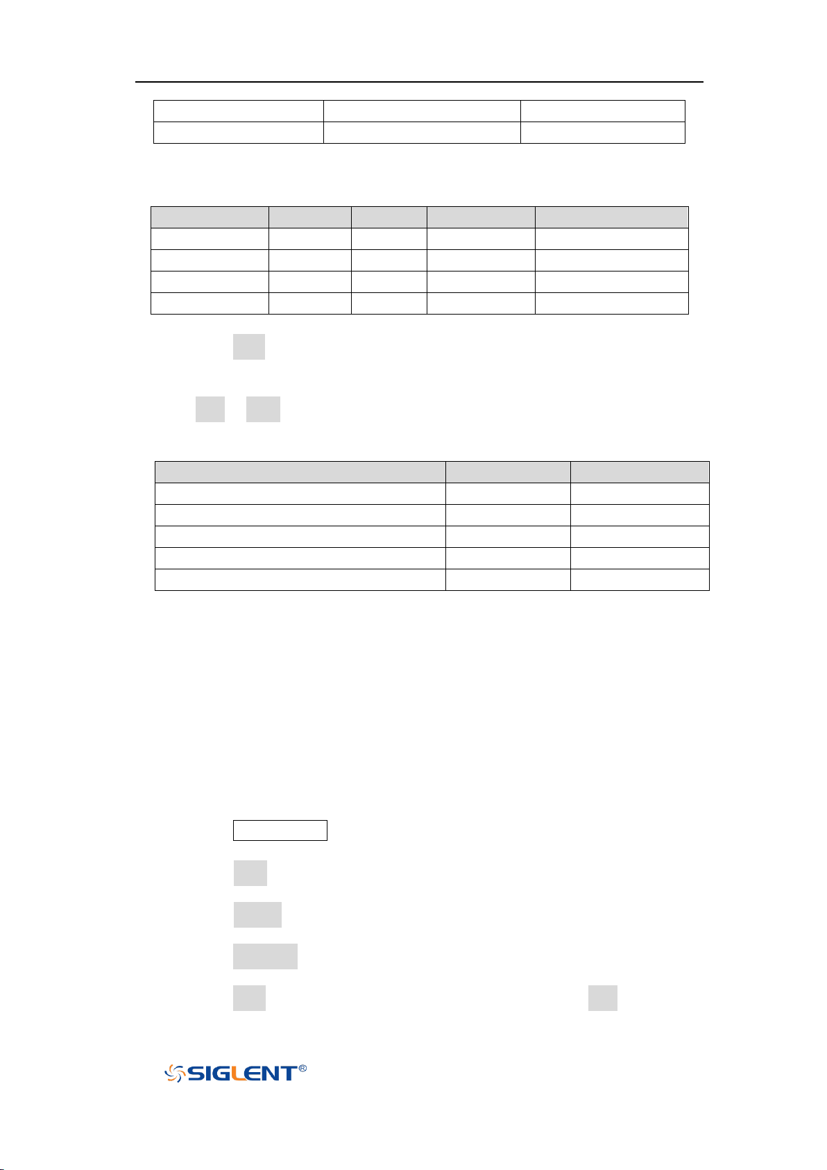
SHS800X&SHS1000X User Manual
WWW.SIGLENT.COM
(line value)/7
7 (line value)/8
8
Of Lines
Of Fields
Interlace
Trigger Line
Trigger Field
800
1
1:1
800
1
800
1,2,4 or 8
2:1
400
1, 1~2, 1~4, 1~8
800
1,2,4 or 8
4:1
200
1, 1~2, 1~4, 1~8
800
1,2,4 or 8
8:1
100
1, 1~2, 1~4, 1~8
Standard
Field 1
Field 2
NTSC
1 to 262
1 to 263
PAL
1 to 312
1 to 313
HDTV 720P/50, HDTV 720P/60
1 to 750
HDTV 1080P/50, HDTV 1080P/60
1 to 1125
HDTV 1080iP/50, HDTV 1080i/60
1 to 562
1 to 563
The table below takes Of Lines as 800 as an example to explain the relation
between Of Lines, Of Fields, Interlace, Trigger Line and Trigger Field.
5. Press the Sync softkey to select Any or Select trigger mode.
Any: trigger on any of the horizontal sync pulses
Select: trigger on the appointed line and field you have set. Press the
Line or Field softkey; then turn the Universal Knob to set the value.
The following table lists the line numbers per field for each video standard.
The following are exercises to familiarize you with video triggering.
To trigger on a specific line of video
To use Custom video trigger
To Trigger on a Specific Line of Video
Video triggering requires greater than 1/2 division of sync amplitude with any
analog channel as the trigger source.
The example below set to trigger on field 2, line 124 using the NTSC video
standard.
1. Press the Trigger Setup button on the front panel to enter the TRIGGER system
function menu.
2. Press the Type softkey; then use the Universal Knob to select Video and push
down the knob to confirm.
3. Press the Source softkey; turn the Universal Knob to select CH1 as the trigger
source, and press the knob to confirm.
4. Press the Standard softkey; turn the Universal Knob to select NTSC, and press
the knob to confirm.
5. Press the Sync softkey and set the option to Select; press the Line softkey and
71
Page 93
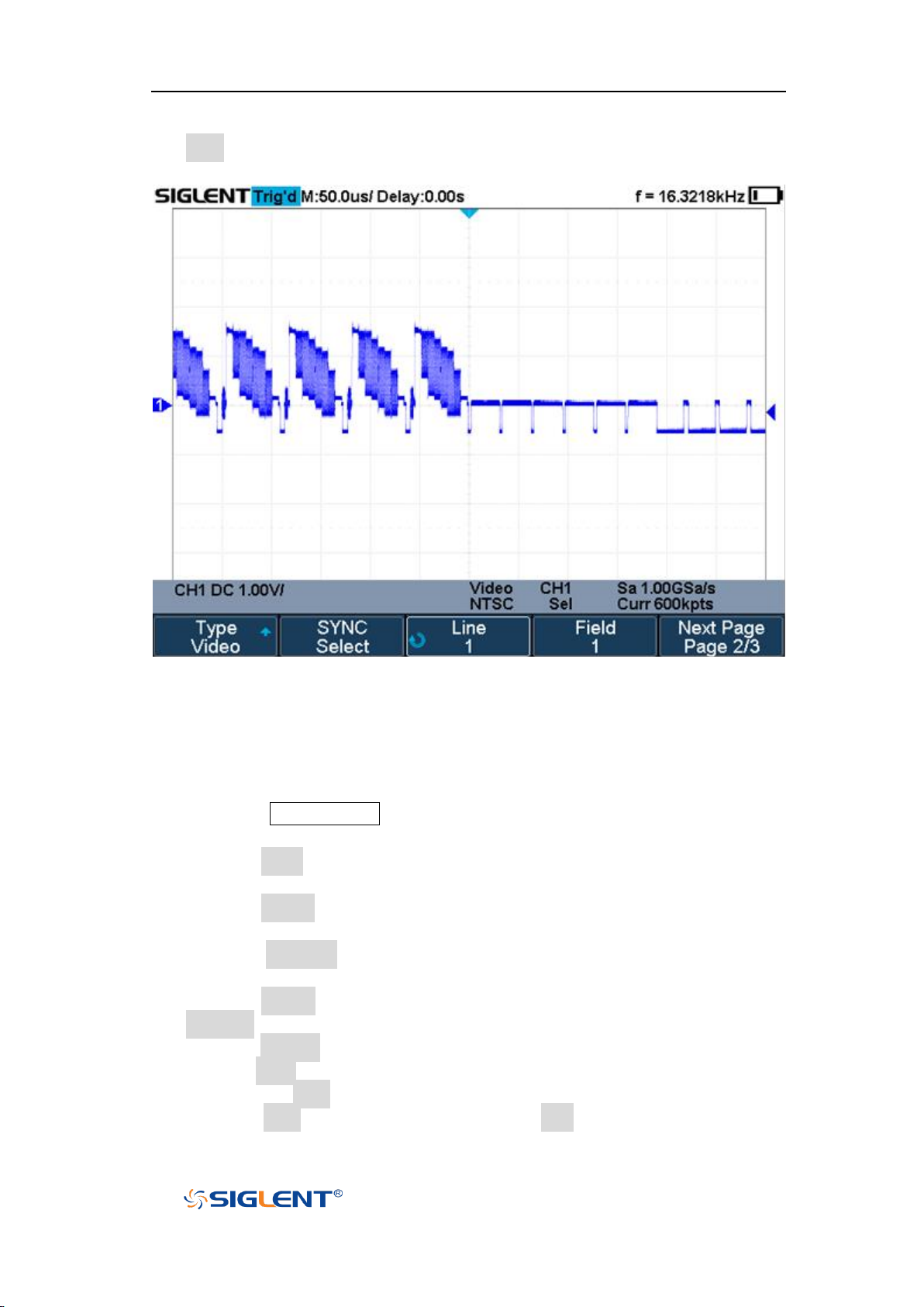
SHS800X&SHS1000X User Manual
WWW.SIGLENT.COM
then turn the universal to select 1 and push the knob to confirm; press the
Field softkey and then turn the Universal Knob to select 1 and push the knob
to confirm
Figure 30 Video Trigger
To Use Custom Video Trigger
Custom video trigger supports frame rate of 25Hz, 30Hz, 50Hz and 60Hz, and the
line range is available from 300 to 2000. The steps below show how to set custom
trigger.
1. Press the Trigger Setup button on the front panel to enter the TRIGGER
function menu.
2. Press the Type softkey; then use the Universal Knob to select Video and push
down the knob to confirm.
3. Press the Source softkey; turn the Universal Knob to select CH1 as the trigger
source, and push down the knob to confirm.
4. Press the Standard softkey; turn the Universal Knob to select Custom, and
push down the knob to confirm.
5. Press the Setting softkey to enter the custom setting function menu. Press the
Interlace softkey; turn the Universal Knob to select the desired value.
6. Press the Of Field softkey; turn the Universal Knob to select the desired value.
7. Press the Sync softkey to enter the TRIG ON menu to set the line and field.
Press the Type softkey to select Select or Any.
If the Type option set to Select, press the Line softkey; turn the Universal
72
Page 94

SHS800X&SHS1000X User Manual
WWW.SIGLENT.COM
Knob to select the desired value. Press the Field softkey; turn the
Universal Knob to select the desired value.
73
Page 95
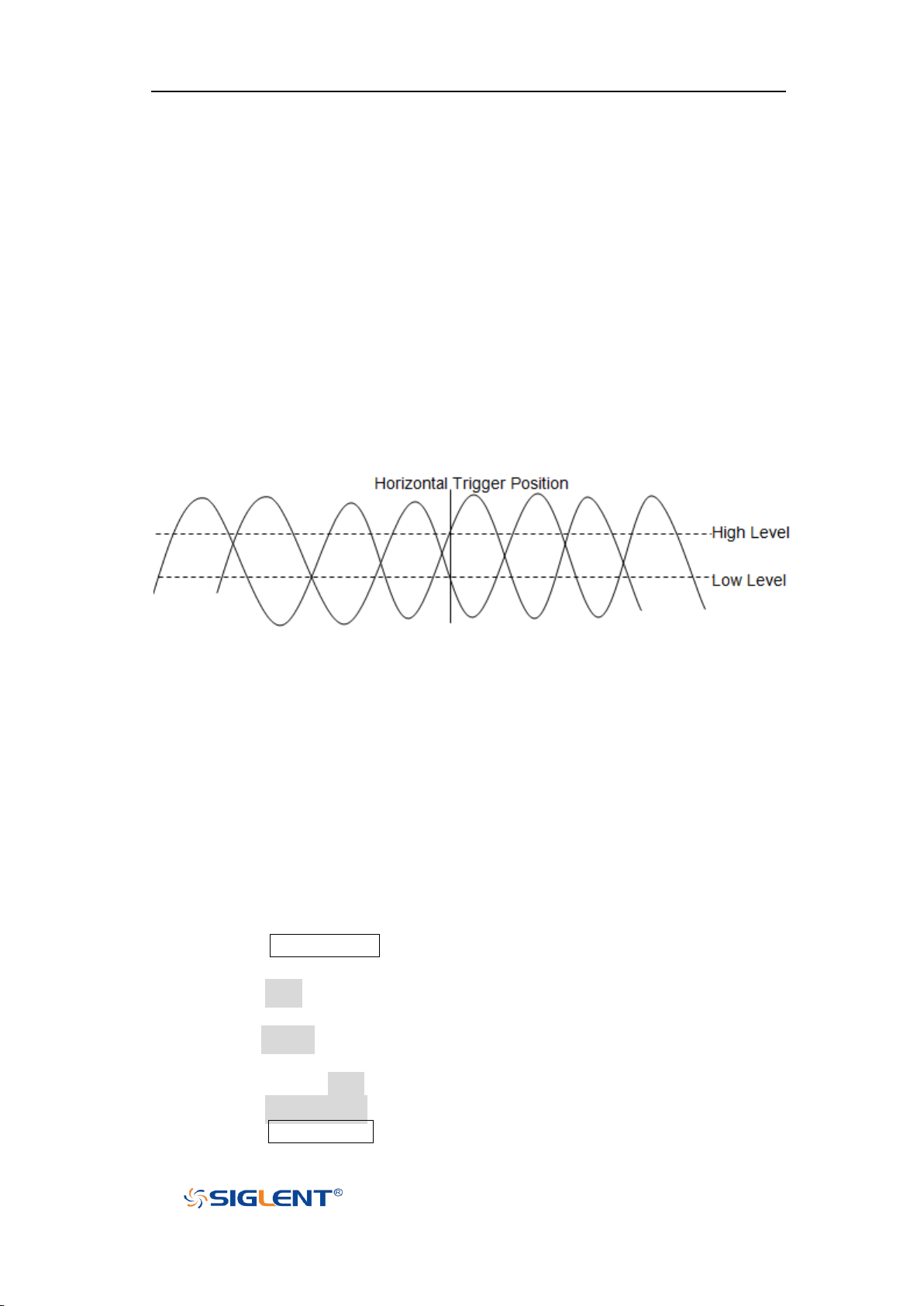
SHS800X&SHS1000X User Manual
WWW.SIGLENT.COM
Window Trigger
Windows trigger provides a high trigger level and a low trigger level. The
instrument triggers when the input signal passes through the high trigger level or
the low trigger level.
There are two kinds of window types: Absolute and Relative. They have different
trigger level adjustment methods. Under Absolute window type, the lower and
the upper trigger levels can be adjusted respectively via the Level knob; under
Relative window type, adjust the Center value to set the window center; adjust
the Delta value to set the window range, the lower and the upper trigger levels
always move together.
If the lower and the upper trigger levels are both within the waveform
amplitude range, the oscilloscope will trigger on both rising and falling
edge.
Suppose the upper trigger level is within the waveform amplitude range
while the lower trigger level is out of the waveform amplitude range. In that
case, the oscilloscope will trigger on rising edge only.
Suppose the lower trigger level is within the waveform amplitude range
while the upper trigger level is out of the waveform amplitude range. In that
case, the oscilloscope will trigger on falling edge only.
To set window trigger via Absolute window type:
1. Press the Trigger Setup button on the front panel to enter the TRIGGER
function menu.
2. Press the Type softkey; then use the Universal Knob to select Window and
push down the knob to confirm.
3. Press the Source softkey; turn the Universal Knob to select CH1 or CH2 as the
trigger source.
4. Press the Window Type softkey to select Absolute.
5. Press the Lower Upper softkey to select Lower or Upper trigger level; then
press the Trigger Level button and turn the Universal Knob to adjust the
74
Page 96
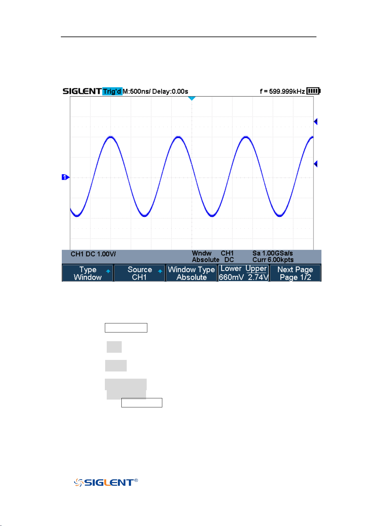
SHS800X&SHS1000X User Manual
WWW.SIGLENT.COM
position. The trigger level values are displayed at the upper right corner of
the screen.
The Lower trigger level cannot be upper than the upper trigger level.
Figure 31 Absolute Window Trigger
To set window trigger via Relative window type:
1. Press the Trigger Setup button on the front panel to enter the TRIGGER system
function menu.
2. Press the Type softkey; then use the Universal Knob to select Window and
push down the knob to confirm.
3. Press the Source softkey; turn the Universal Knob to select CH1 or CH2 as the
trigger source.
4. Press the Window Type softkey to select Relative.
5. Press the Center Delta softkey to select Center or Delta trigger level mode;
then press the Trigger Level button and turn the Universal Knob to adjust the
position.
75
Page 97
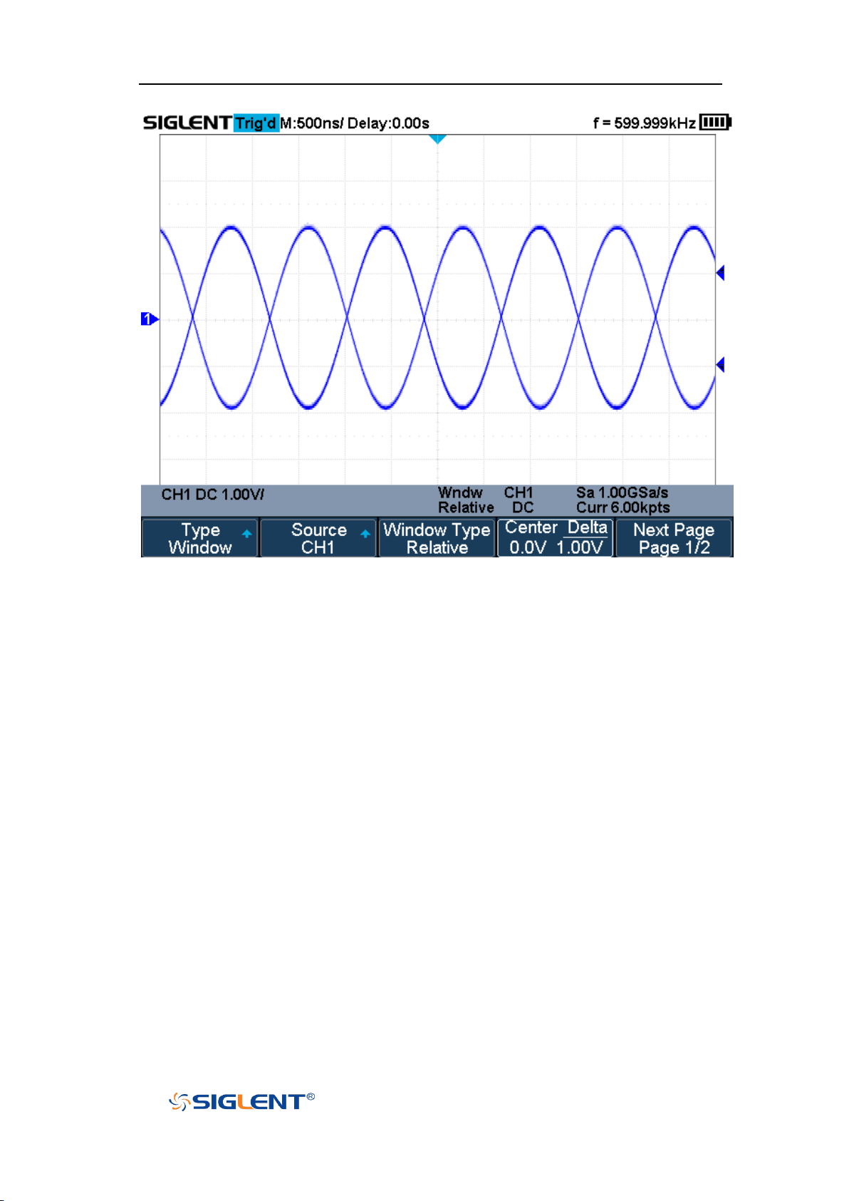
SHS800X&SHS1000X User Manual
WWW.SIGLENT.COM
Figure 32 Relative Window Trigger
Coupling and noise reject can be set in Window trigger, see the sections "Trigger
Coupling" and "Noise Rejection" for details.
76
Page 98
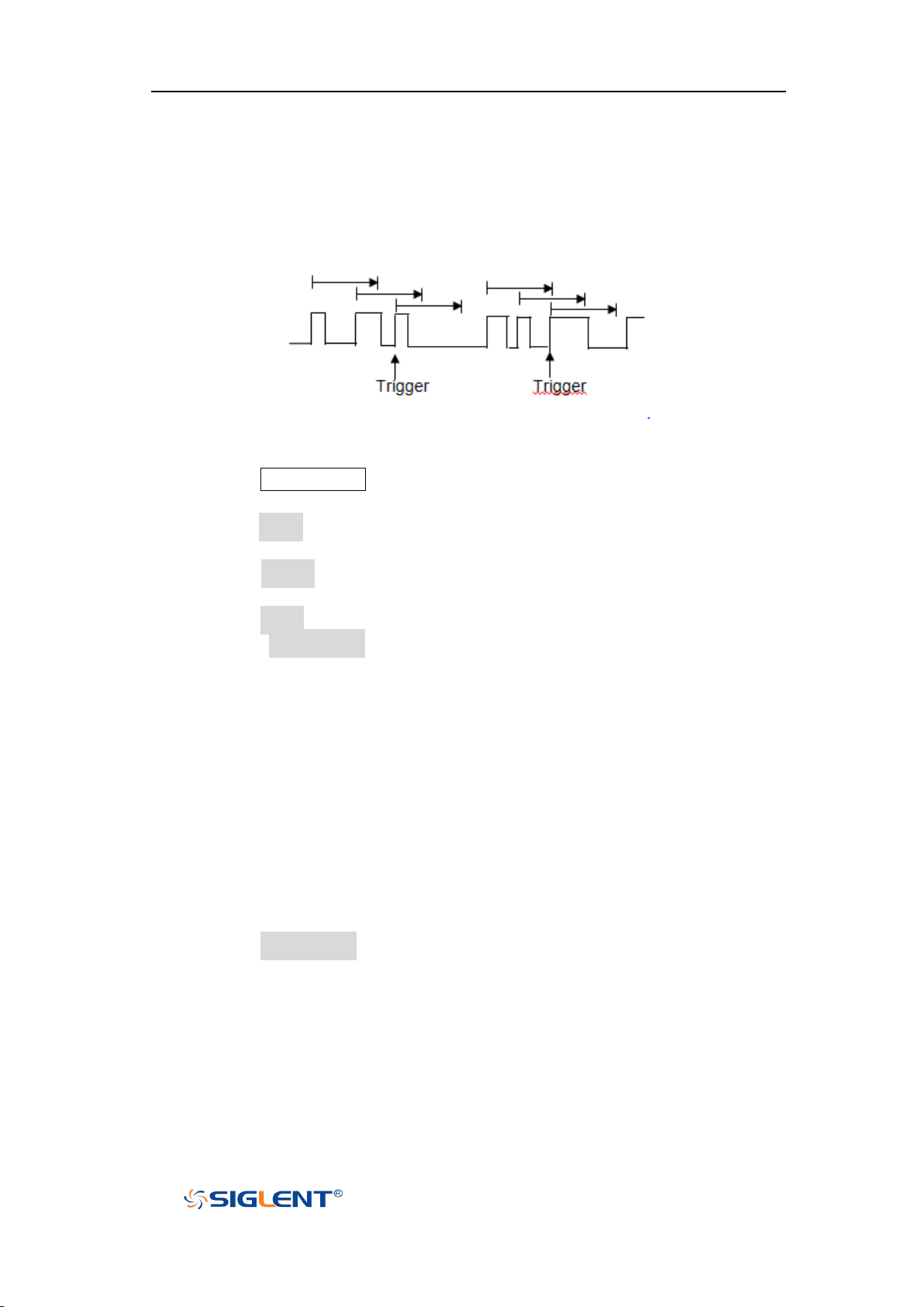
SHS800X&SHS1000X User Manual
WWW.SIGLENT.COM
Interval Trigger
Trigger when the times difference between the neighboring rising or falling
edges meets the time limit (<=, >=, [--,--], --][--).
To set interval trigger:
1. Press the Trigger Setup button on the front panel to enter the TRIGGER system
function menu.
2. Press the Type softkey; then use the Universal Knob to select Interval and
push down the knob to confirm.
3. Press the Source softkey; turn the Universal Knob to select CH1 or CH2 as the
trigger source.
4. Press the Slope softkey to select rising or falling edge.
5. Press the Limit Range softkey; turn the Universal Knob to select desired
condition.
<= (less than a time value): trigger when the input signal's positive or
negative pulse time is lower than the specified time value.
>= (greater than a time value): trigger when the input signal's positive or
negative pulse time is greater than the specified time value.
[--,--] (within a range of time value):trigger when the input signal's
positive or negative pulse time is greater than the specified lower limit of
time and lower than the specified upper limit of time value.
--][-- (outside a range of time value): trigger when the input signal's
positive or negative pulse time is greater than the specified upper limit of
time and lower than the specified lower limit of time value.
6. Press the Time Setting softkey (<=, >=, [--,--],--][--), turn the Universal Knob to
select the desired value.
77
Page 99
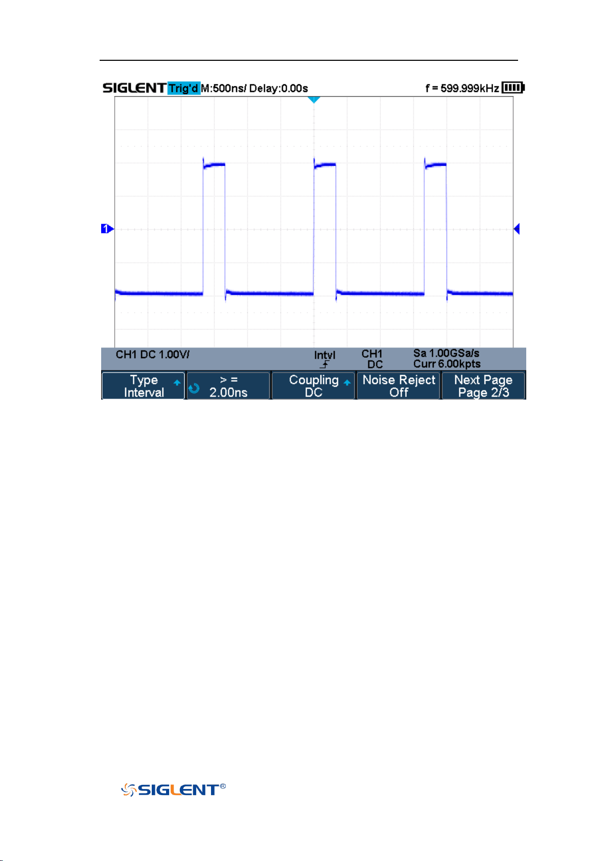
SHS800X&SHS1000X User Manual
WWW.SIGLENT.COM
Figure 33 Interval Trigger
Coupling and noise reject can be set in interval trigger, see the sections "Trigger
Coupling" and "Noise Rejection" for details.
78
Page 100
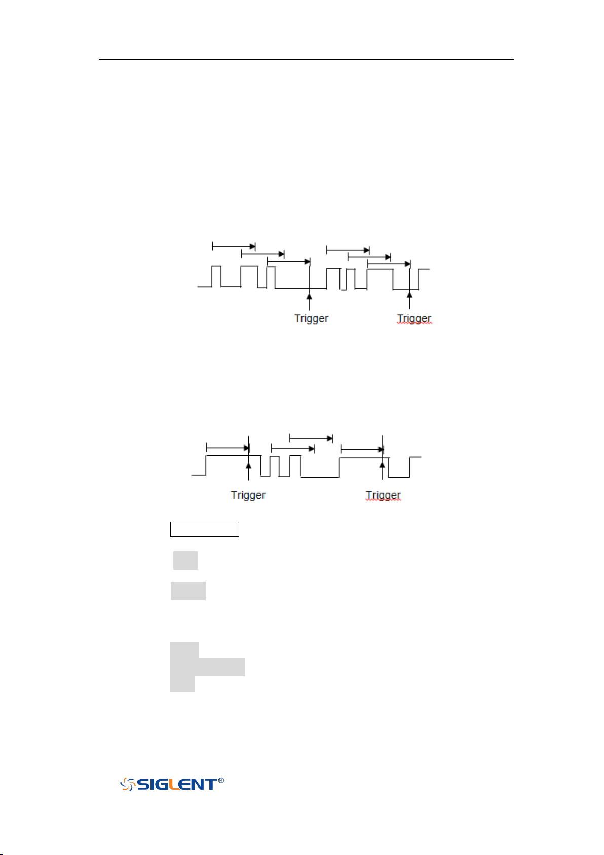
SHS800X&SHS1000X User Manual
WWW.SIGLENT.COM
Dropout Trigger
Dropout trigger includes two types: edge and state.
Edge
Trigger when the time interval (△T) from when the rising edge (or falling edge) of
the input signal passes through the trigger level to when the neighboring rising
edge (or falling edge) passes through the trigger level is greater than the timeout
time set, as shown in the figure below.
State
Trigger when the time interval (△T) from when the rising edge (or falling edge) of
the input signal passes through the trigger level to when the neighboring falling
edge (or rising edge) passes through the trigger level is greater than the timeout
time set, as shown in the figure below.
To set edge Dropout trigger:
1. Press the Trigger Setup button on the front panel to enter the TRIGGER system
function menu.
2. Press the Type softkey; then use the Universal Knob to select Dropout and
push down the knob to confirm.
3. Press the Source softkey; turn the Universal Knob to select CH1 or CH2 as the
trigger source. The current trigger source is displayed at the upper right
corner of the screen. Select channel with signal input as trigger source to
obtain stable trigger.
4. Press the Slope softkey to select rising or falling edge.
5. Press the OverTime Type softkey to select Edge.
6. Press the Time softkey; turn the Universal Knob to select the desired value.
79
 Loading...