

Page 1

Digital Oscilloscopes Series
Programming Guide
Digital Oscilloscopes Series
RC01020-E01C
SIGLENT TECHNOLOGIES CO., LTD
1
Page 2

Digital Oscilloscopes Series
Catalogue
Programming Overview ...................................................... 4
Build communication ........................................................ 4
Install NI-VISA ........................................................................... 4
Connect the instrument ............................................................... 8
How To Remote Control ................................................... 9
a. User-defined Programming ..................................................... 9
b .Send SCPI Commands via NI-VISA ...................................... 9
About these Commands & Queries ................................... 10
How are they listed? ........................................................ 10
How are they described? ................................................. 10
Where can they be used? ................................................ 10
Command Notation ............................................................ 12
Table of Commands & Queries ......................................... 13
Programming Examples .................................................. 149
Example of VC++ ......................................................... 150
Example of VB.............................................................. 159
Example of MATLAB ................................................... 167
Example of LabVIEW .................................................. 170
Example of C# .............................................................. 173
2
Page 3

Digital Oscilloscopes Series
Using Sockets Examples ............................................... 176
Example of C ........................................................................... 176
Index ................................................................................ 178
3
Page 4

Digital Oscilloscopes Series
Programming Overview
This chapter introduces how to execute remote communications
between a SIGLENT digital oscilloscope and the computer. It also
introduces how to establish a remote control link over a
communication bus.
Build communication
Install NI-VISA
Before programming, you need to install National
Instruments NI-VISA library, which you can download from the
National Instruments web-site. Currently, NI-VISA is packaged
in two versions: a full version and a Run-Time Engine version.
The full version includes the NI device drivers and a tool named
NI MAX that is a user interface to control the device. The RunTime Engine is much smaller than the full version and only
includes NI device driver.
For example, you can get the NI-VISA 5.4 full version from:
http://www.ni.com/download/ni-visa-5.4/4230/en/.
You also can download NI-VISA Run-Time Engine 5.4 to
your PC and install it as the default selection. Its installation
process is similar with the full version.
After you downloaded the file you can follow the steps
below to install it:
4
Page 5
Digital Oscilloscopes Series
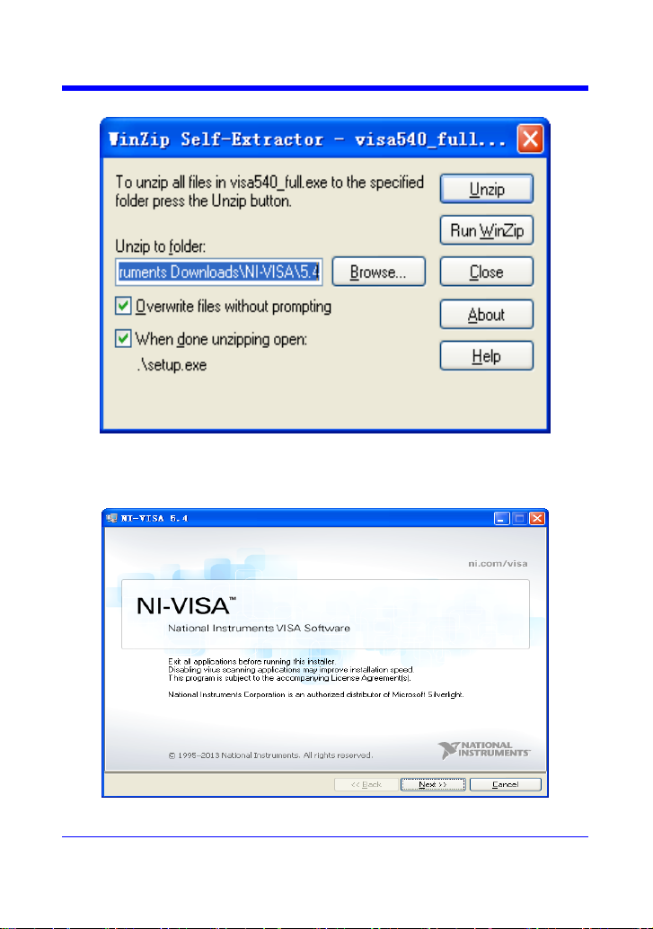
a.Double click the visa540_full.exe, dialog shown as below:
b. Click Unzip, the installation process will automatically launch
after unzipping files. If your computer needs to install .NET
Framework 4, its Setup process will auto start.
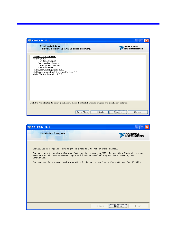
c.The NI-VISA installing dialog is shown above. Click Next to
5
Page 6

Digital Oscilloscopes Series
start the installation process.
Set the install path, default path is ―C:\Program Files\National
Instruments\‖, you can change it. Click Next, dialog shown as
above.
d. Click Next twice, in the License Agreement dialog, select the
6
Page 7
Digital Oscilloscopes Series
―I accept the above 2 License Agreement(s).‖,and click Next,
dialog shown as below:
e.Click Next to run installation.
Now the installation is complete, reboot your PC.
7
Page 8
Digital Oscilloscopes Series
Connect the instrument
Depending on your specific model your oscilloscope may be able to
communicate with a PC through the USB or LAN interface. This
manual takes the USB as an example. (For instructions to
communicate with a PC through the LAN interface see the User
Manual.)
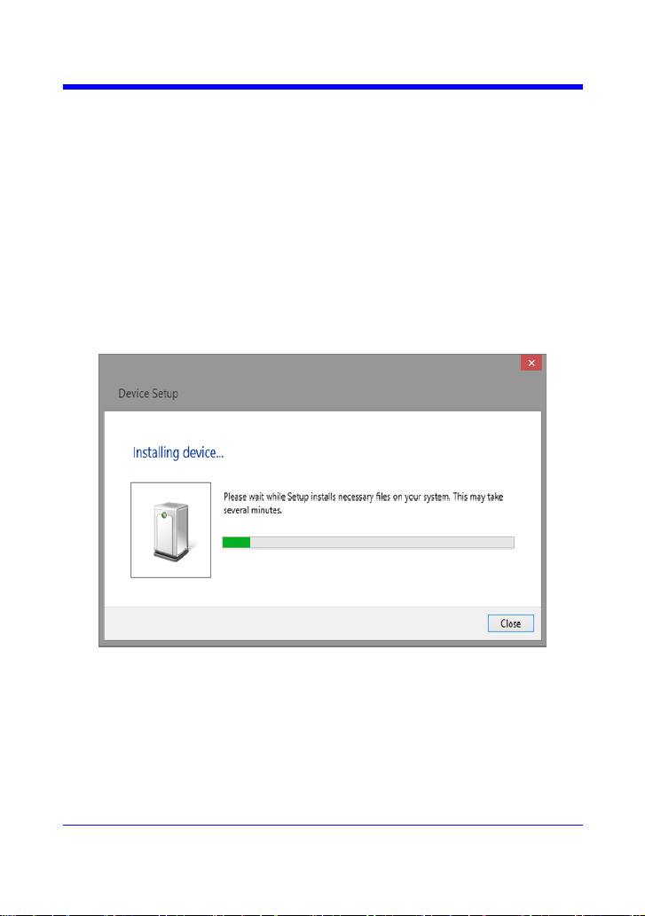
a.Connect the USB Device interface at the rear panel of the
oscilloscope and the USB Host interface of the PC using a USB
cable. Assuming your PC is already turned on, turn on your
oscilloscope and your PC will display the ―Device Setup‖ screen
as it automatically installs the device driver as shown below.
b. Wait for the installation to complete and then proceed to the
next step.
8
Page 9

Digital Oscilloscopes Series
How To Remote Control
a. User-defined Programming
Users can use SCPI commands to program and control the
digital oscilloscope. For details, refer to the introductions in
"Programming Examples".
b .Send SCPI Commands via NI-VISA
You can control the oscilloscope remotely by sending SCPI
commands via NI-VISA software.
9
Page 10

Digital Oscilloscopes Series
About these Commands & Queries
This section lists describes the remote control commands and
queries recognized by the instrument. All commands and queries can
be executed in either local or remote state.
The description for each command or query, with syntax and other
information, begins on a new page. The name (header) is given in
both long and short form at the top of the page, and the subject is
indicated as a command or query or both. Queries perform actions
such as obtaining information, and are recognized by the question
mark (?) following the header.
How are they listed?
The descriptions are listed in alphabetical order according to their
long form. Thus the description of ATTENUATION, whose short
form is ATTN, is listed before that of AUTO SETUP, whose short
form is ASET.
How are they described?
In the descriptions themselves, a brief explanation of the function
performed is given. This is followed by a presentation of the formal
syntax, with the header given in Upper-and-Lower-Case characters
and the short form derived from it in ALL UPPER-CASE characters.
Where applicable, the syntax of the query is given with the format of
its response.
Where can they be used?
The commands and queries listed here can be used for all Siglent‘s
Digital Oscilloscope Series digital instruments.
10
Page 11

Digital Oscilloscopes Series
Applicable to the following models
SDS1000CML/CML+
SDS1000DL/DL+
SDS1000CNL/CNL+
SDS1000/1000X/1000X-S/1000X+/1000X-E
SDS2000/SDS2000X
SPO models
SDS1000X/1000X+/SDS1000X-E
SDS2000/2000X
Certain commands are only applicable to SPO oscilloscopes models
and are described accordingly.
SPO oscilloscopes models are in the table below.
What is an SPO model?
SPO model uses Siglent-innovated waveform acquisition and
graphics processing engine which supports high capture rate, multi-
level intensity grading and color temperature display, with deep
memory storage and the use of new digital trigger technology
supports rich trigger types and precise trigger. All of these
technologies are collectively known as SPO (Super Phosphor
Oscilloscope) technology.
11
Page 12

Digital Oscilloscopes Series
Command Notation
The following notation is used in the commands:
< > Angular brackets enclose words that are used as placeholders,
of which there are two types: the header path and the data
parameter of a command.
: = A colon followed by an equals sign separates a placeholder
from the description of the type and range of values that may
be used in a command instead of the placeholder.
{} Braces enclose a list of choices, one of which one must be
made.
[ ] Square brackets enclose optional items.
… An ellipsis indicates that the items both to its left and right
may be repeated a number of times.
As an example, consider the syntax notation for the command to set
the vertical input sensitivity:
<channel>:VOLT_DIV <v_gain>
<channel> : = {C1, C2, C3, C4}
<v_gain>: = 2 mV to 10 V
The first line shows the formal appearance of the command, with
<channel> denoting the placeholder for the header path and
<v_gain> the placeholder for the data parameter specifying the
desired vertical gain value. The second line indicates that one of four
channels must be chosen for the header path. And the third explains
that the actual vertical gain can be set to any value between 2 mV
and 10 V.
12
Page 13
Digital Oscilloscopes Series
Short Form
Long Form
Subsystem
What the Command or
Query Does
ACQW
ACQUIRE_WAY
ACQUISITION
Specifies the acquisition
mode.
ALST?
ALL_STATUS?
STATUS
Reads and clears
the contents of all
status registers.
ARM
ARM_ACQUISITION
ACQUISITION
Changes acquisition state
from ―stopped‖ to
―single‖.
ATTN
ATTENUATION
CHANNEL
Selects the vertical
attenuation factor of the
probe
ACAL
AUTO_CALIBRATE
SYSTEM
Enables or disables
automatic calibration.
ASET
AUTO_SETUP
ACQUISITION
Adjusts vertical, time base
and trigger parameters.
AUTTS
AUTO_TYPESET
ACQUISITION
Selects the display type of
automatic setup.
AVGA
AVERAGE_ACQUIRE
ACQUISITION
Selects the average times
of average acquisition.
BWL
BANDWIDTH_LIMIT
CHANNEL
Enables/disables the
bandwidth-limiting lowpass filter.
BUZZ
BUZZER
SYSTEM
Controls the built-in
piezo-electric buzzer.
*CAL?
*CAL?
SYSTEM
Performs complete
internal calibration of the
instrument.
CHDR
COMM_HEADER
SYSTEM
Controls formatting of
query responses.
*CLS
*CLS
STATUS
Clears all status data
registers.
CMR?
CMR?
STATUS
Reads and clears the
Command error Register
(CMR).
CONET
COMM_NET
SYSTEM
Specifies network
addresses of scope and
printers.
CPL
COUPLING
CHANNEL
Selects the specified input
channel‘s coupling mode.
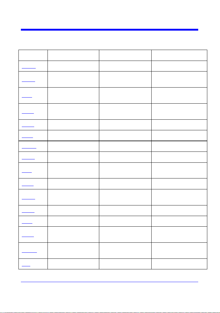
Table of Commands & Queries
13
Page 14

Digital Oscilloscopes Series
CRMS
CURSOR_MEASURE
CURSOR
Specifies the type of
cursor/parameter
measurement.
CRST
CURSOR_SET?
CURSOR
Allows positioning of any
one of eight cursors.
CRTY
CURSOR_TYPE
CURSOR
Select the type of cursor.
CRVA?
CURSOR_VALUE?
CURSOR
Returns trace values
measured by specified
cursors.
CSVS
CSV_SAVE
SAVE/RECALL
Saves specified waveform
data of CSV format to
USB device.
CYMT
CYMOMETER
MEASURE
Returns the current
cymometer value which
displaying on the screen.
DATE
DATE
SYSTEM
Changes the date/time of
the internal real-time
clock.
DDR?
DDR?
STATUS
Clears the Device
Dependent Register
(DDR).
DEF
DEFINE?
MATH
Specifies math expression
for function evaluation.
DTJN
DOT_JOIN
DISPLAY
Controls the interpolation
lines between data points.
*ESE
*ESE
STATUS
Sets the Standard Event
Status Enable register
(ESE).
*ESR?
*ESR?
STATUS
Reads, clears the Event
Status Register (ESR).
EXR?
EXR?
STATUS
Reads, clears the
Execution error Register
(EXR).
FPAR
FRAME_PARAM
HISTORY
Get frame param.
FRAM
FRAME_SET
HISTORY
History Frame No. set.
FTIM
FRAME_TIME
HISTORY
Get frame Acq. Time.
FILT
FILTER
FUNCTION
Enables or disables the
filter of specified source.
FILTS
FILT_SET
FUNCTION
Selects the type of filter,
and sets the limit value of
filter.
FFTW
FFT_WINDOW
MATH
Selects the window of
FFT.
FFTZ
FFT_ZOOM
MATH
Selects the zoom in/out
14
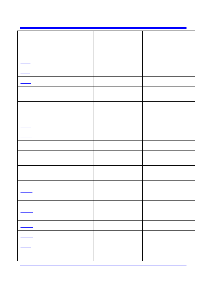
Page 15
Digital Oscilloscopes Series
times of FFT trace.
FFTS
FFT_SCALE
MATH
Selects the vertical scale
of FFT trace.
FFTU
FFT_UNIT
MATH
Selects the vertical scale
unit of FFT trace.
FFTT
FFT_TDIV
MATH
Selects the horizontal
scale of FFT trace.
FFTP
FFT_POSITION
MATH
Selects the position of FFT
trace.
FFTC
FFT_CENTER
MATH
Selects the center
frequcency of FFT trace.
FFTF
FFT_FULLSCREEN
MATH
Enables or disables to
display the FFT trace full
screen.
GRDS
GRID_DISPLAY
DISPLAY
Selects the type of grid
HMAG
HOR_MAGNIFY
ZOOM
Horizontally expands the
selected expansion trace.
HPOS
HOR_POSITION
ZOOM
Horizontally positions
intensified zone‘s center.
*IDN?
*IDN?
SYSTEM
For identification
purposes.
INTS
INTENSITY
DISPLAY
Sets the grid or trace/text
intensity level.
INR?
INR?
STATUS
Reads, clears INternal
state change Register
(INR).
INVS
INVERT_SET
DISPLAY
Invert the trace or the
math waveform of
specified source.
MTVP
MATH_VERT_POS
MATH
Controls the vertical
position of math
waveform of specified
source.
MTVD
MATH_VERT_DIV
MATH
Controls the vertical
sensitivity of math
waveform of specified
source.
MEAD
MEASURE_DELY
MEASURE
Controls the type of delay
measure
MENU
MENU
DISPLAY
Enables or disables to
display the current menu.
MSIZ
MEMORY_SIZE
ACQUISITION
Returns the maximal
memory size
OFST
OFFSET
CHANNEL
Allows output channel
vertical offset adjustment.
15
Page 16
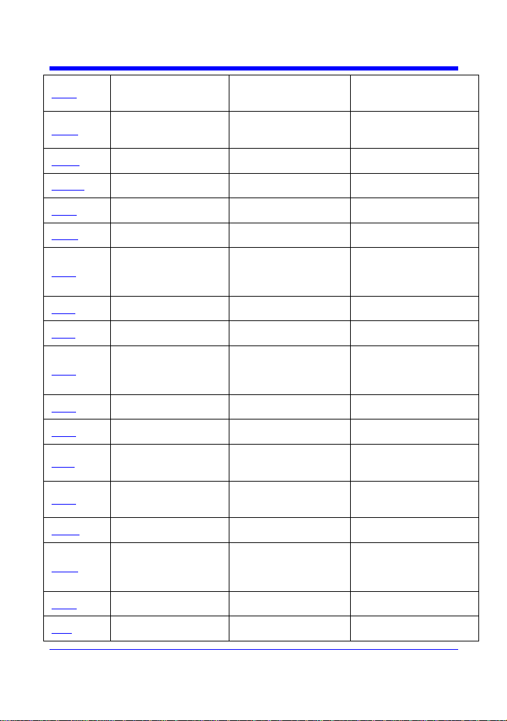
Digital Oscilloscopes Series
*OPC
*OPC
STATUS
Sets the OPC bit in the
Event Status Register
(ESR).
PACL
PARAMETER_CLR
PASS/FAIL
Clears all current
parameters in Custom,
Pass/Fail.
PACU
PARAMETER_CUSTO
M
MEASURE
Controls parameters with
customizable qualifiers.
PAVA?
PARAMETER_VALU
E?
MEASURE
Returns current parameter,
mask test values.
PESU
PERSIST_SETUP
DISPLAY
Selects display persistence
duration.
PNSU
PANEL_SETUP
SAVE/RECALL
Complements the
*SAV/*RST commands.
PFDS
PF_DISPLAY
PASS/FAIL
Enables or disables to
display the test and the
message options of
pass/fail.
PFST
PF_SET
PASS/FAIL
Sets the X mask and the Y
mask.
PFSL
PF_SAVELOAD
PASS/FAIL
Saves or recalls the
created mask setting.
PFCT
PF_CONTROL
PASS/FAIL
Selects the ―operate‖,
―output‖ and the ―stop on
output‖ which are the
options of pass/fail.
PFSC
PF_SOURCE
PASS/FAIL
Selects the source of
pass/fail.
PFBF
PF_BUFFER
PASS/FAIL
Selects the ―output‖ which
is the options of pass/fail.
PFFS
PF_FAIL_STOP
PASS/FAIL
Selects the ―stop on fail‖
which is the options of
pass/fail.
PFOP
PF_OPERATION
PASS/FAIL
Selects the ―operate‖
which is the options of
pass/fail.
PFCM
PF_CREATEM
PASS/FAIL
Creates the mask of the
pass/fail.
PFDD
PF_DATEDIS
PASS/FAIL
Return the number of the
pass/fail monitor which
can be displayed on the
screen.
*RCL
*RCL
SAVE/RECALL
Recalls one of five nonvolatile panel setups.
REC
RECALL
SAVE/RECALL
Recalls a waveform file
from the current directory
16
Page 17
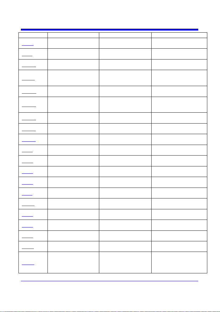
Digital Oscilloscopes Series
on mass storage.
RCPN
RECALL_PANEL
SAVE/RECALL
Recalls a front-panel setup
from mass storage.
*RST
*RST
SAVE/RECALL
The *RST command
initiates a device reset.
REFCL
REF_CLOSE
FUNCTION
Close the reference
function
REFDI
REF_DISPALY
FUNCTION
Enable or disable the
current reference channel
show on the screen
REFLA
REF_LOCATION
FUNCTION
Set the current reference
channel
REFPO
REF_POISITION
FUNCTION
Set the vertical offset of
the current reference
channel
REFSA
REF_SAVE
FUNCTION
Save the waveform to the
current channel
REFSC
REF_SCLALE
FUNCTION
Set the vertical scale of the
current reference channel
REFSR
REF_SOURCE
FUNCTION
Set the source to the
current reference channel
REFS
REF_SET
FUNCTION
Sets the reference
waveform and its options.
*SAV
*SAV
SAVE/RECALL
Stores current state in nonvolatile internal memory.
SCDP
SCREEN_DUMP
FUNCTION
Causes a screen dump to
controller.
SCSV
SCREEN_SAVE
DISPLAY
Controls the automatic
screen saver.
*SRE
*SRE
STATUS
Sets the Service Request
Enable register (SRE).
*STB?
*STB?
STATUS
Reads the contents of
IEEE 488.
STOP
STOP
TRIGGER
Immediately stops signal
acquisition.
STPN
STORE_PANEL
SAVE/RECALL
Stores front-panel setup to
mass storage.
SAST
SAMPLE_STATUS
ACQUISITION
Return the acquisition
status of the scope
SARA
SAMPLE_RATE
ACQUISITION
Return the sample rate of
the scope
SANU
SAMPLE_NUM
ACQUISITION
Return the number of
sampled points available
from last acquisition and
the trigger position
17
Page 18
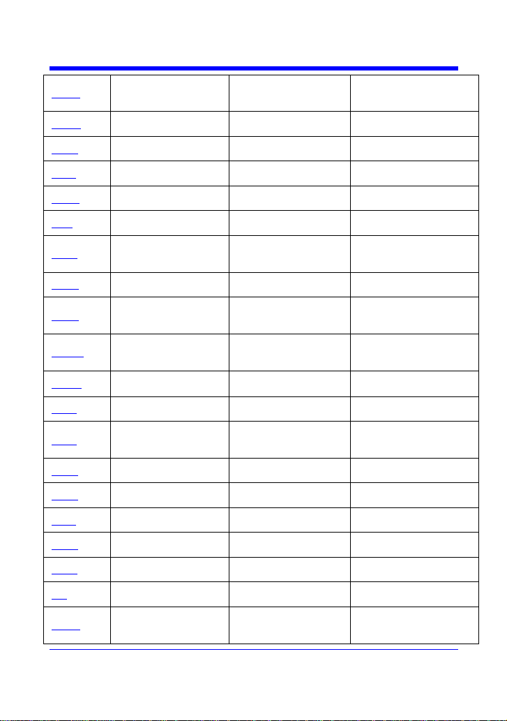
Digital Oscilloscopes Series
SET50
SETTO%50
TRIGGER
Sets the trigger level of the
trigger source to the centre
of the signal amplitude.
SKEW
SKEW
CHANNEL
Sets the skew of specified
trace.
SXSA
SINXX_SAMPLE
ACQUISITION
Sets the type of the
interpolation.
TDIV
TIME_DIV
ACQUISITION
Modifies the time base
setting.
TMPL
TEMPLATE
WAVEFORM
TRANSFER
Produces a complete
waveform template copy.
TRA
TRACE
CHANNEL
Enables or disables the
display of a trace.
TRCP
TRIG_COUPLING
TRIGGER
Sets the coupling mode of
the specified trigger
source.
TRDL
TRIG_DELAY
ACQUISITION
Sets the time at which the
trigger is to occur.
TRLV
TRIG_LEVEL
TRIGGER
Adjusts the trigger level of
the specified trigger
source.
TRLV2
TRIG_LEVEL2
TRIGGER
Adjusts the second trigger
level of the specified
trigger source.
TRMD
TRIG_MODE
TRIGGER
The trigger mode.
TRSE
TRIG_SELECT
TRIGGER
Selects the condition that
will trigger acquisition.
TRSL
TRIG_SLOPE
TRIGGER
Sets the trigger slope of
the specified trigger
source.
TRWI
TRIG_WINDOW
TRIGGER
Return relative height of
the trigger window
TRPA
TRIG_PATTERN
TRIGGER
Sets the condition of the
pattern trigger
UNIT
UNIT
CHANNEL
Sets the unit of specified
trace.
VPOS
VERT_POSITION
MATH
Adjusts the vertical
position of the FFT trace.
VDIV
VOLT_DIV
CHANNEL
Sets the vertical
sensitivity.
WF
WAVEFORM
WAVEFORMTRANS
Gets the waveform from
the instrument.
WFSU
WAVEFORM_SETUP
WAVEFORMTRANS
Specifies amount of
waveform data to go to
controller.
18
Page 19

Digital Oscilloscopes Series
XYDS
XY_DISPLAY
DISPLAY
Enables or disables to
display the XY format
19
Page 20

Commands & Queries
ACQUISITION
ACQUIRE_WAY,ACQW
Command /Query
DESCRIPTION
The ACQUIRE_WAY command specifies the
acquisition mode.
The ACQUIRE_ WAY? Query returns the current
acquisition mode.
COMMAND SYNTAX
ACQUIRE_WAY <mode>[,<time>]
<mode> :={SAMPLING,PEAK_DETECT,AVERA
GE,HIGH_RES }
<time> := {4, 16, 32, 64,128,256,512,etc}
Note:
1. The [HIGH_RES] option of mode is applicable
for SPO models.
2. The <time> parameter only can be set with the
average acquisition mode. And its options vary
with model.
QUERY SYNTAX
ACQUIRE_WAY?
RESPONSE FORMAT
ACQUIRE_WAY <mode>[,<time>]
EXAMPLE
The following command sets the acquisition mode
to average mode and also sets the average value to
16.
Command message:
ACQW AVERAGE,16
RELATED COMMANDS
AVGA,
Digital Oscilloscopes Series
20
Page 21

Digital Oscilloscopes Series
STATUS
ALL_STATUS? , ALST?
Query
DESCRIPTION
The ALL_STATUS? Query reads and clears
the contents of all status registers: STB, ESR,
INR, DDR, CMR, EXR and URR except for
the MAV bit (bit 6) of the STB register. For an
interpretation of the contents of each register,
refer to the appropriate status register.
The ALL_STATUS? Query is useful in a
complete overview of the state of the
instrument.
QUERY SYNTAX
ALl_STatus?
RESPONSE FORMAT
ALl_STatus
STB,<value>,ESR,<value>,INR,<value>,DDR
,<value>,CMR,<value>,
EXR,<value>,URR,<value>
<value> : = 0 to 65535
EXAMPLE
The following instruction reads the contents of
all the
status registers:
Command message:
ALST?
Response message:
ALST STB, 0, ESR, 52, INR, 5, DDR, 0,
CMR, 4,
EXR, 24, URR, 0
RELATED COMMANDS
*CLS, CMR? , DDR? ,*ESR? , EXR? ,
*STB? , URR?
21
Page 22

Digital Oscilloscopes Series
ACQUISITION
ARM_ACQUISITION, ARM
Command
DESCRIPTION
The ARM_ACQUISITION command enables
the signal acquisition process by changing the
acquisition state (trigger mode) from―stopped‖
to ―single‖.
COMMAND SYNTAX
ARM acquisition
EXAMPLE
The following command enables signal
acquisition:
Command message:
ARM
RELATED COMMANDS
STOP, *TRG, TRIG_MODE, WAIT
22
Page 23

Digital Oscilloscopes Series
CHANNEL
ATTENUATION, ATTN
Command /Query
DESCRIPTION
The ATTENUATION command selects the
vertical attenuation factor of the probe. Values
of 1, 5, 10, 50, 100, 500, and 1000 may be
specified.
The ATTENUATION? Query returns the
attenuation factor of the specified channel.
COMMAND SYNTAX
<channel>: ATTeNuation <attenuation>
<channel> : = {C1, C2, C3, C4}
<attenuation>:= {0.1, 0.2, 0.5, 1, 2, 5, 10, 20,
50, 100, 200, 500, 1000, 2000, 5000, 10000}
QUERY SYNTAX
<channel>: ATTeNuation?
RESPONSE FORMAT
<channel>: ATTeNuation <attenuation>
EXAMPLE
The following command sets to 100 the
attenuation factor of Channel 1:
Command message:
C1:ATTN 100
23
Page 24

Digital Oscilloscopes Series
SYSTEM
AUTO_CALIBRATE, ACAL
Command /Query
DESCRIPTION
The AUTO_CALIBRATE command is used to
enable or disable the quick calibration of the
instrument.
The quick calibration may be disabled by
issuing the command ACAL OFF. Whenever
it is convenient, a *CAL? Query may be issued
to fully calibrate the oscilloscope.
The response to the AUTO_CALIBRATE?
Query indicates whether quick-calibration is
enabled.
This command is only used in the CFL series
of instruments.
COMMAND SYNTAX
Auto_CALibrate <state>
<state> : = {ON, OFF}
QUERY SYNTAX
Auto_CALibrate?
RESPONSE FORMAT
Auto_CALibrate <state>
EXAMPLE
The following instruction disables quick
calibration:
Command message:
ACAL OFF
RELATED COMMANDS
*CAL?
24
Page 25

Digital Oscilloscopes Series
ACQUISITION
AUTO_SETUP, ASET
Command
DESCRIPTION
The AUTO_SETUP command attempts to
identify the waveform type and automatically
adjusts controls to produce a usable display of
the input signal.
COMMAND SYNTAX
AUTO_SETUP
EXAMPLE
The following command instructs the
oscilloscope to perform an auto-setup:
Command message:
ASET
RELATED COMMANDS
AUTTS
25
Page 26

Digital Oscilloscopes Series
ACQUISITION
AUTO_TYPESET, AUTTS
Command /Query
DESCRIPTION
The AUTO_TYPESET command selects the
specified type of automatically adjusting
which is used to display.
COMMAND SYNTAX
AUTO_TYPESET <type>
<type> : = {SP,MP,RS,DRP,RC}
SP means only one period to be displayed, MP
means multiple periods to be displayed, RS
means the waveform is triggered on the rise
side, DRP means the waveform is triggered on
the drop side, and RC means to go back to the
state before auto set.
QUERY SYNTAX
AUTO_TYPESET?
RESPONSE FORMAT
AUTO_TYPESET <type>
EXAMPLE
The following command sets the type of
automatic adjustment to multiple periods:
Command message:
AUTTS MP
RELATED COMMANDS
ASET
26
Page 27

Digital Oscilloscopes Series
ACQUISITION
AVERAGE_ACQUIRE, AVGA
Command /Query
DESCRIPTION
The AVERAGE_ACQUIRE command selects
the average times of average acquisition.
The response to the AVERAGE_ACQUIRE
query indicates the times of average
acquisition.
COMMAND SYNTAX
AVERAGE_ACQUIRE <time>
<time> : = {4, 16, 32, 64,128,256,etc}
Note:
The <time> parameter‘s options vary with model.
QUERY SYNTAX
AVERAGE_ACQUIRE?
RESPONSE FORMAT
AVERAGE_ACQUIRE <time>
EXAMPLE
The following turns the average times of average
acquisition 16:
Command message:
AVGA 16
27
Page 28

Digital Oscilloscopes Series
ACQUISITION
BANDWIDTH_LIMIT, BWL
Command /Query
DESCRIPTION
BANDWIDTH_LIMIT enables or disables the
bandwidth-limiting low-pass filter. If the
bandwidth filters are on, it will limit the
bandwidth to reduce display noise. When you
turn Bandwidth Limit ON, the Bandwidth
Limit value is set to 20 MHz. It also filters the
signal to reduce noise and other unwanted
high frequency components.
The response to the BANDWIDTH_LIMIT?
Query indicates whether the bandwidth filters
are on or off.
COMMAND SYNTAX
BandWidth_Limit <channel>, <mode>
[, <channel>, <mode> [, <channel>, <mode>
[, <channel>, <mode>]]]
<channel>: = {C1, C2, C3, C4}
<mode>: = {ON, OFF}
QUERY SYNTAX
BandWidth_Limit?
RESPONSE FORMAT
BandWidth_Limit <channel>, <mode>
[,<channel>,<mode> [, <channel>, <mode> [,
<channel>,<mode>]]]
EXAMPLE
The following turns on the bandwidth filter for all
channels, when Global_BWL is on (as it is by
default)
The following turns the bandwidth filter on for
Channel 1only:
Command message:
BWL C1, ON
28
Page 29

Digital Oscilloscopes Series
MISCELLANEOUS
BUZZER, BUZZ
Command /Query
DESCRIPTION
The BUZZER command enables or disables
sounds for keypresses and other functionss.
The response to the BUZZER? query indicates
whether the sound switch is enabled or not.
COMMAND SYNTAX
BUZZer <state>
<state>:= {ON, OFF}
QUERY SYNTAX
BUZZER?
RESPONSE FORMAT
BUZZER <state>
EXAMPLE
Sending the following code will enable the
oscilloscope sound.
Command message:
BUZZ ON
29
Page 30

Digital Oscilloscopes Series
MISCELLANEOUS
*CAL?
Query
DESCRIPTION
The *CAL? query causes the oscilloscope to
perform an internal self-calibration and
generates a response.
QUERY SYNTAX
*CAL?
RESPONSE FORMAT
*CAL <diagnostics>
<diagnostics> : = 0
0 = Calibration successful
EXAMPLE
The following instruction forces a self-calibration:
Command message:
*CAL?
Response message:
*CAL 0
RELATED COMMANDS
AUTO_CALIBRATE
30
Page 31

COMMUNICATION
COMM_HEADER, CHDR
Command/ Query
DESCRIPTION
The COMM_HEADER command controls the
way the oscilloscope formats responses to
queries. There are three response formats:
LONG, in which responses start with the long
form of the header word; SHORT, where
responses start with the short form of the
header word; and OFF, for which headers are
omitted from the response and units in
numbers are suppressed.
Unless you request otherwise, the SHORT
response format is used.
This command does not affect the
interpretation of messages sent to the
oscilloscope. Headers can be sent in their long
or short form regardless of the
COMM_HEADER setting.
Querying the vertical sensitivity of Channel 1
may result in one of the following responses:
COMM_HEADER RESPONSE
LONG C1:VOLT_DIV 200E-3 V
SHORT C1:VDIV 200E-3 V
OFF 200E-3
COMMAND SYNTAX
Comm_HeaDeR <mode>
<mode> : = {SHORT, LONG, OFF}
QUERY SYNTAX
Comm_HeaDeR?
RESPONSE FORMAT
Comm_HeaDeR <mode>
EXAMPLE
The following code sets the response header format
to SHORT:
Command message:
CHDR SHORT
31
Digital Oscilloscopes Series
Page 32

Digital Oscilloscopes Series
STATUS
*CLS
Command
DESCRIPTION
The *CLS command clears all the status data
registers.
COMMAND SYNTAX
*CLS
EXAMPLE
The following command causes all the status data
registers to be cleared:
Command message:
*CLS
RELATED COMMANDS
ALL_STATUS, CMR, DDR, *ESR, EXR, *STB, URR
32
Page 33

STATUS
CMR?
Query
DESCRIPTION
The CMR? Query reads and clears the contents of
the Command error Register (CMR) see table
next page---which specifies the last syntax error
type detected by the instrument.
QUERY SYNTAX
CMR?
RESPONSE FORMAT
CMR <value>
<value>: = 0 to 14
EXAMPLE
The following instruction reads the contents of the
CMR register:
Command message:
CMR?
Response message:
CMR 0
RELATED COMMANDS
ALL_STATUS? ,*CLS
Command Error Status Register Structure (CMR)
Value
Description
1
Unrecognized command/query header
2
Invalid character
3
Invalid separator
4
Missing parameter
5
Unrecognized keyword
6
String error
7
Parameter cannot allowed
8
Command String Too Long
9
Query cannot allowed
10
Missing Query mask
11
Invalid parameter
12
Parameter syntax error
13
Filename too long
ADDITIONAL INFORMATION
Digital Oscilloscopes Series
33
Page 34

Digital Oscilloscopes Series
MISCELLANEOUS
COMM_NET, CONET
Command /Query
DESCRIPTION
The COMM_NET command changes the IP
address of the oscilloscope‘s internal network
interface.
The COMM_NET? query returns the IP address of
the oscilloscope‘s internal network interface.
COMMAND SYNTAX
COMM_NET <ip_add0>, <ip_add1>, <ip_add2>,
<ip_add3>
< ip_add >:= 0 to 255
QUERY SYNTAX
COMM_NET?
RESPONSE FORMAT
COMM_NET <ip_add0>, <ip_add1>, <ip_add2>,
<ip_add3>
EXAMPLE
This instruction will change the IP address to
10.11.0.230:
Command message:
CONET 10,11,0,230
34
Page 35

FUNCTION
COUNTER,COUN
Command /Query
DESCRIPTION
The COUNTER command enables or disables the
cymometer display on the screen of instrument.
The response to the COUNTER? query indicates
whether the cymometer is displayed on the screen
of instrument.
COMMAND SYNTAX
COUNTER <state>
< state >: = {ON, OFF}
QUERY SYNTAX
COUNTER?
RESPONSE FORMAT
COUNTER <state>
EXAMPLE
The following command enables the cymometer
display
Command message:
COUN ON
Note:
This command is suitable for non-SPO models.
Digital Oscilloscopes Series
35
Page 36

Digital Oscilloscopes Series
ACQUISITION
COUPLING, CPL
Command /Query
DESCRIPTION
The COUPLING command selects the coupling
mode of the specified input channel.
The COUPLING? query returns the coupling mode
of the specified channel.
COMMAND SYNTAX
<channel>: CouPLing <coupling>
<channel>: = {C1, C2, C3, C4}
<coupling>: = {A1M, A50, D1M, D50, GND}
The A of the <coupling> is alternating current. The
D of the <coupling> is direct current.1M and 50 is
the impedance of input. Some series (CML)
couldn‘t have the set of input impedance.
Note:
The options of <coupling> vary with models. If
your oscilloscope is an SPO model, the options are
{A1M, A50, D1M, D50, GND}, otherwise the
options are {A1M, D1M, GND}.
QUERY SYNTAX
<channel>: CouPLing?
RESPONSE FORMAT
<channel>: CouPLing <coupling>
EXAMPLE
The following command sets the coupling of
Channel 2 to 50 ΩDC:
Command message:
C2:CPL D50
36
Page 37

CURSOR
CURSOR_AUTO,CRAU
Command
DESCRIPTION
The CURSOR_AUTO command changes the
cursor mode to auto mode.
COMMAND SYNTAX
CRAU
EXAMPLE
The following code changes the cursor mode to
auto mode
Command message:
CRAU
Note:
This command is suitable for non-SPO models.
Digital Oscilloscopes Series
37
Page 38

Digital Oscilloscopes Series
CURSOR
CURSOR_MEASURE, CRMS
Command /Query
DESCRIPTION
The CURSOR_MEASURE command specifies the
mode of cursor or parameter measurement to be
displayed
The CURSOR_MEASURE? query indicates which
cursors or parameter measurements are currently
displayed.
COMMAND SYNTAX
CuRsor_MeaSure <mode>
Format 1:
<mode>=:{OFF, ON}
Format 2:
<mode>=:{OFF, MANUAL,TRACK}
Note:
1. If the oscilloscope doesn‘t have auto cursor, you
should use format 1. OFF means manual mode,
ON means track mode.
2. If the oscilloscope has auto cursor, you should
use format 2.
QUERY SYNTAX
CuRsor_MeaSure?
RESPONSE FORMAT
CuRsor_MeaSure <mode>
EXAMPLE
The following command determines cursor
function is turned off:
Command message:
CRMS OFF
RELATED COMMANDS
CURSOR_VALUE, PARAMETER_VALUE
38
Page 39

CURSOR
CURSOR_SET, CRST
Command /Query
DESCRIPTION
The CURSOR_SET command allows the user to
position any one of the eight independent cursors at
a given screen location. The positions of the cursors
can be modified or queried even if the required
cursor is not currently displayed on the screen.
When setting a cursor position, a trace must be
specified, relative to which the cursor will be
positioned.
The CURSOR_SET? Query indicates the current
position of the cursor(s). The values returned
depend on the grid type selected.
Notation
VREF
The voltage-value of curA under
manual cursor mode.
VDIF
The voltage-value of curB under
manual cursor mode.
TREF
The time value of curA under manual
cursor mode.
TDIF
The time value of curB under manual
cursor mode.
HREF
The time value of curA under Track
cursor mode.
HDIF
The time value of curB under Track
cursor mode.
COMMAND SYNTAX
<trace>:CuRsor_SeT<cursor>,<position>[,<cursor
>,<position>,<cursor> ,<position>]
< trace >: = {C1, C2, C3, C4}
<cursor>: =
{ VREF,VDIF,TREF,TDIF,HRDF,HDIF}
<position>(horizontal):= {-7 to 7 DIV }
<position>(vertical):= {-4 to 4 DIV}
Note:
1. The horizontal position‘s value is related to the
size of screen. For SPO models, the position‘s
value is in the range of -7 to 7 and you need add
the unit (DIV) to the value. In non-SPO models
39
Digital Oscilloscopes Series
Page 40

Digital Oscilloscopes Series
it‘s in the range of -8 to 8.
2. The vertical position‘s value is related to the size
of screen. For SPO models, you need add the unit
(DIV) to the value.
QUERY SYNTAX
<trace>: CuRsor_SeT? [<cursor>, …<cursor>]
<cursor>:=
{ VREF,VDIF,TREF,TDIF,HREF,HDIF}
RESPONSE FORMAT
<trace>:CuRsor_SeT <cursor>, <position> [,
<cursor>, <position>, <cursor>, <position>]
EXAMPLE
The following command positions the VREF
and VDIF cursors at +3 DIV and −1 DIV
respectively, using C1 as a reference:
Command message:
C1:CRST VREF, 3DIV, VDIF, −1DIV
RELATED COMMANDS
CURSOR_MEASURE,CURSOR_VALUE,
PARAMETER_VALUE
40
Page 41
Digital Oscilloscopes Series
CURSOR
CURSOR_VALUE?, CRVA?
Query
DESCRIPTION
The CURSOR_VALUE? query returns the values
measured by the specified cursors for a given trace.
(The PARAMETER_VALUE? query is used to
obtain measured waveform parameter values.)
Notation
HREL
the delta time-value, reciprocal of
delta time-value, curA time-value
and curB time-value.
VREL
the delta volt-value, curA volt-value
and curB volt-value under manual
cursor mode
Note:
For non-SPO models, VREL is the delta volt-value
under manual cursor mode.
QUERY SYNTAX
<trace>: CuRsor_Value? [<mode>,…<mode>]
<trace>: = { C1, C2, C3, C4}
<mode>: = { HREL,VREL}
RESPONSE FORMAT
<trace>: CuRsor_Value HREL,
<delta_hori>,< 1/delta_hori >,< curA _value>,
<curB _value>
<trace>: CuRsor_Value VREL,<delta_vert>,< curA
_value>,< curB _value>
EXAMPLE
The following query reads the vertical value under
manual cursor mode (VREL) on Channel 2:
Command message:
C2:CRVA? VREL
Response message:
C2:CuRsor_Value VREL,3.96v,-0.02v,-3.98v
RELATED COMMANDS
CURSOR_SET, PARAMETER_VALUE
41
Page 42

CURSOR
CURSOR_TYPE, CRTY
Command /Query
DESCRIPTION
The CURSOR_TYPE command specifies the type
of cursor to be displayed.
COMMAND SYNTAX
CURSOR_TYPE <type>
<mode>=:{X, Y,X-Y}
QUERY SYNTAX
CURSOR_TYPE?
RESPONSE FORMAT
CURSOR_TYPE <type>
EXAMPLE
The following command determines cursor
type is Y:
Command message:
CRTY Y
RELATED COMMANDS
CURSOR_MEASURE
Note:
This command is suitable for SPO models.
Digital Oscilloscopes Series
42
Page 43

SAVE/RECALL
CSV_SAVE, CSVS
Command /Query
DESCRIPTION
The CSV_SAVE command selects the specified
option of storing CSV format waveform.
The CSV_SAVE? query returns the option of
storing waveform data of CSV format.
COMMAND SYNTAX
Format1:
CSV_SAVE SAVE,<state>
The option SAVE is that if the waveform data is
stored with parameter.
<save>:= {OFF, ON}
Format2:
CSV_SAVE DD,<DD>,SAVE,<state>
The option DD is the data depth which is saved as.
The option SAVE is that if the waveform data is
stored with parameter.
<DD>:= {MAX,DIS} the meaning of MAX is
saved as the maximum data depth. The meaning of
DIS is saved as the date depth which is displayed
on the screen
<save>:= {OFF, ON}
Note:
This command varies with models, so there are two
formats. If your oscilloscope can set the data depth
of CSV file which will be saved, you should use
Format2, such as non-SPO models, otherwise you
should use Format1.
QUERY SYNTAX
CSV_SAVE?
RESPONSE FORMAT
CSV_SAVE SAVE, <state>
EXAMPLE
The following command sets ―para‖ save to off
Command message:
Format1:
CSV_SAVE SAVE,OFF
Format2:
CSVS DD,DIS,SAVE,OFF
43
Digital Oscilloscopes Series
Page 44

Digital Oscilloscopes Series
FUNCTION
CYMOMETER?, CYMT?
Query
DESCRIPTION
The response to the CYMOMETER? query is the
value of cymometer which displaying on the screen
of the instrument. When the signal frequency is less
than 10Hz, it returns 10Hz.
QUERY SYNTAX
CYMOMETER?
RESPONSE FORMAT
CYMOMETER <option>
EXAMPLE
The following instruction returns the value of
cymometer which displaying on the screen of
the instrument.
Response message:
CYMT 10Hz
44
Page 45

Digital Oscilloscopes Series
SYSTEM
DATE
Command /Query
DESCRIPTION
The DATE command changes the date/time of the
oscilloscope‘s internal real-time clock.
The command is only used in the CFL series
instrument.
COMMAND SYNTAX
DATE <day>, <month>, <year>, <hour>,
<minute>, <second>
<day>: = 1 to 31
<month>: = {JAN, FEB, MAR, APR, MAY, JUN,
JUL, AUG, SEP,OCT, NOV, DEC}
<year>: = 1990 to 2089
<hour>: = 0 to 23
<minute>: = 0 to 59
<second>: = 0 to 59
QUERY SYNTAX
DATE?
RESPONSE FORMAT
DATE <day>, <month>, <year>, <hour>,
<minute>, <second>
EXAMPLE
This instruction will change the date to
NOV. 1, 2009 and the time to 14:38:16:
Command message:
DATE 1, NOV, 2009,14,38,16
Note:
This command is suitable for the model which has this function.
45
Page 46

Digital Oscilloscopes Series
STATUS
DDR?
Query
DESCRIPTION
The DDR? Query reads and clears the contents of
the Device Dependent or device specific error
Register (DDR). In the case of a hardware failure,
the DDR register specifies the origin of the failure.
QUERY SYNTAX
DDR?
RESPONSE FORMAT
DDR <value>
<value>: = 0 to 65535
EXAMPLE
The following instruction reads the contents of
the DDR register:
Command message:
DDR?
Response message:
DDR 0
RELATED COMMANDS
ALL_STATUS? ,*CLS
46
Page 47

Digital Oscilloscopes Series
FUNCTION
DEFINE, DEF
Command /Query
DESCRIPTION
The DEFINE command specifies the mathematical
expression to be evaluated by a function.
COMMAND SYNTAX
DEFine EQN,‘<equation>‘
Note:
<equation> is the mathematical expression
Function Equations
<source1> + <source2>
Addition
<source1> - <source2>
Subtraction
<source1>*<source2>
Multiplication
<source1>/<source2>
Ratio
FFT(source x)
FFT
INTG(source x)
Integral
DIFF(source x)
Differentiator
SQRT(source x)
Square Root
QUERY SYNTAX
DEFine?
RESPONSE FORMAT
DEFine EQN,'<equation>'
EXAMPLE
Command message:
DEFine EQN,'C1*C2'
47
Page 48

Digital Oscilloscopes Series
DISPLAY
DOT_JOIN,DTJN
Command /Query
DESCRIPTION
The DOT_JOIN command controls the
interpolation lines between data points.
COMMAND SYNTAX
DoT_JoiN <state>
<state>: = {ON, OFF}
QUERY SYNTAX
DoT_JoiN?
RESPONSE FORMAT
DoT_JoiN <state>
EXAMPLE
The following instruction turns off the interpolation
lines:
Command message:
DTJN OFF
48
Page 49

Digital Oscilloscopes Series
STATUS
*ESE
Command /Query
DESCRIPTION
The *ESE command sets the Standard Event Status
Enable register (ESE). This command allows one or
more events in the ESR register to be reflected in
the ESB summary message bit (bit 5) of the STB
register.
COMMAND SYNTAX
*ESE <value>
<value>: = 0 to 255
QUERY SYNTAX
*ESE?
RESPONSE FORMAT
*ESE <value>
EXAMPLE
The following instruction allows the ESB bit to be
set if a user request (URQ bit 6, i.e. decimal 64)
and/or a device dependent error (DDE bit 3, i.e.
decimal 8) occurs. Summing these values yields the
ESE register mask 64+8=72.
Command message:
*ESE 72
RELATED COMMANDS
*ESR
49
Page 50
STATUS
*ESR?
Command /Query
DESCRIPTION
The *ESR? query reads and clears the contents of
the Event Status Register (ESR). The response
represents the sum of the binary values of the
register bits 0 to 7.
QUERY SYNTAX
*ESR?
RESPONSE FORMAT
*ESER<value>
<value>: = 0 to 255
EXAMPLE
The following instruction reads and clears the
contents of the ESR register:
Command message:
*ESR?
Response message:
*ESR 0
RELATED COMMANDS
ALL_STATUS, *CLS, *ESE
Standard Event Status Register (ESR)
Bit
Bit Value
Bit Name
Description
Note
15~8 0
reserved by IEEE 488.2
7
128
PON 1 Power off-to-ON transition as
occurred
(1)
6
64
URQ 1 User Request has been issued
(2)
5
32
CME 1 Command parser Error has been
detected
(3)
4
16
EXE 1 Execution Error detected
(4)
3 8 DDE 1 Device specific Error occurred
(5) 2 4
QYE 1 Query Error occurred
(6)
1 2 RQC 1 Instrument never requests bus control
(7)
0 1 OPC 1 Instrument never requests bus control
(8)
ADDITIONAL INFORMATION
Digital Oscilloscopes Series
50
Page 51

Digital Oscilloscopes Series
Notes
(1) The Power On (PON) bit is always turned on (1) when the unit is powered up.
(2) The User Request (URQ) bit is set true (1) when a soft key is pressed. An associated register
URR identifies which key was selected. For further details refer to the URR? query.
(3) The CoMmand parser Error bit (CME) is set true (1) whenever a command syntax error is
detected. The CME bit has an associated CoMmand parser Register (CMR) which specifies
the error code. Refer to the query CMR? for further details.
(4) The EXecution Error bit (EXE) is set true (1) when a command cannot be executed due to
some device condition (e.g. oscilloscope in local state) or a semantic error. The EXE bit has
an associated Execution Error Register (EXR) which specifies the error code. Refer to query
EXR? for further details.
(5) The Device specific Error (DDE) is set true (1) whenever a hardware failure has occurred at
power-up, or execution time, such as a channel overload condition, a trigger or a timebase
circuit defect. The origin of the failure may be localized via the DDR? or the self test *TST?
query.
(6) The Query Error bit (QYE) is set true (1) whenever (a) an attempt is made to read data from
the Output Queue when no output is either present or pending, (b) data in the Output Queue
has been lost, (c) both output and input buffers are full (deadlock state), (d) an attempt is
made by the controller to read before having sent an <END>, (e) a command is received
before the response to the previous query was read (output buffer flushed).
(7) The ReQuest Control bit (RQC) is always false (0), as the oscilloscope has no GPIB
controlling capability.
(8) The OPeration Complete bit (OPC) is set true (1) whenever *OPC has been received, since
commands and queries are strictly executed in sequential order. The oscilloscope starts
processing a command only when the previous command has been entirely executed.
51
Page 52

STATUS
EXR?
Query
DESCRIPTION
The EXR? query reads and clears the contents of
the Execution error Register (EXR). The EXR
register specifies the type of the last error detected
during execution.
QUERY SYNTAX
EXR?
RESPONSE FORMAT
EXR <value>
<value>: = to
EXAMPLE
The following instruction reads the contents of the
EXR register:
Command message:
EXR?
Response message (if no fault):
EXR 0
RELATED COMMANDS
ALL_STATUS, *CLS
Execution Error Status Register Structure (EXR)
Value
Description
21
Permission error. The command cannot be executed in local mode.
22
Environment error. The instrument is not configured to correctly process a
command. For instance, the oscilloscope cannot be set to RIS at a slow timebase.
23
Option error. The command applies to an option which has not been installed.
25
Parameter error. Too many parameters specified.
26
Non-implemented command.
32
Waveform descriptor error. An invalid waveform descriptor has been detected.
36
Panel setup error. An invalid panel setup data block has been detected.
50
No mass storage present when user attempted to access it.
53
Mass storage was write protected when user attempted to create, or a file, to delete a
file, or to format the device.
58
Mass storage file not found.
59
Requested directory not found.
61
Mass storage filename not DOS compatible, or illegal filename.
62
Cannot write on mass storage because filename already exists.
ADDITIONAL INFORMATION
Digital Oscilloscopes Series
52
Page 53

Digital Oscilloscopes Series
HISTORY
FRAME_PARAM?, FPAR?
Query
DESCRIPTION
The FRAME_PARAM command is used to get
frame param include descriptor name, product
name, the total number of frames and so on.
QUERY SYNTAX
FPAR?
Note:
This command is used with the history function.
RESPONSE FORMAT
The format of the response is binary.
EXAMPLE
The following command gets the frame
parameters:
Command message:
FPAR?
53
Page 54

Digital Oscilloscopes Series
HISTORY
FRAME_SET, FRAM
Command
DESCRIPTION
The FRAME_SET command is used to set history
current frame number.
COMMAND SYNTAX
FRAM <frame_num>
Frame_num = 0 to the max frame number
Note: This command is used with the history
function.
EXAMPLE
The following command sets current frame number
to 50.
Command message:
FRAM 50
54
Page 55

Digital Oscilloscopes Series
HISTORY
FRAME_TIME?, FTIM?
Query
DESCRIPTION
The FRAME_TIME command is used to get
current frame Acq. Time.
QUERY SYNTAX
FTIM?
Note: This command is used in history function
opening.
RESPONSE FORMAT
The format of response is binary.
EXAMPLE
The following query reads the current frame
Acq.Time.
Command message:
FTIM?
55
Page 56

FUNCTION
FILTER,FILT
Command /Query
DESCRIPTION
The FILTER command enables or disables filter of
the specified trace.
The response to the FILTER? query indicates
whether the filter of specified trace is enabled.
COMMAND SYNTAX
<channel>:FILTER <state>
<channel>: = {C1,C2,C3,C4}
<state>: = {ON,OFF}
QUERY SYNTAX
<channel>:FILTER?
RESPONSE FORMAT
<channel>:FILTER <state>
EXAMPLE
The following command enables the filter of
channel 1:
Command message:
C1:FILT ON
RELATED COMMANDS
FILTS
Note:
This command is suitable for non-SPO models.
Digital Oscilloscopes Series
56
Page 57

Digital Oscilloscopes Series
FUNCTION
FILT_SET,FILTS
Command /Query
DESCRIPTION
The FILT_SET command selects the specified type
of filter, and sets the limit value of filter.
The response to the FILT_SET? query indicates
current parameter of the filter.
COMMAND SYNTAX
<channel>:FILT_SET
TYPE,<type>,<limit>,<limit_value>
<channel>: = {C1,C2,C3,C4}
<type>: = {LP,HP,BP,BR}
<limit>: = {UPPLIMIT,LOWLIMIT}
Note:
1. LP is low-pass, HP is high-pass, BP is band-pass,
BR is band-reject.
2. If seted the <limit>, the <type> must be related.
QUERY SYNTAX
<channel>: FILT_SET?
RESPONSE FORMAT
<channel>:FILTER TYPE,<type>,<limit>,<limitvalue >
EXAMPLE
The following command changes the type of filter
to band-pass, and sets the up-limit to 200 KHz and
the low-limit to 100 KHz:
Command message:
C1:FILTS TYPE,BP,
UPPLIMIT,200KHz,LOWLIMIT,100KHz
RELATED COMMANDS
FILT
Note:
This command is suitable for non-SPO models.
57
Page 58

Digital Oscilloscopes Series
MATH
FFT_WINDOW,FFTW
Command /Query
DESCRIPTION
The FFT_WINDOW command selects the window
of FFT(Fast Fourier Transform algorithm).
The response to the FFT_WINDOW? query
indicates current window of FFT
COMMAND SYNTAX
FFT_WINDOW <window>
<window >: = {RECT,BLAC,HANN,HAMM}
RECT is short for rectangle.
BLAC is short for Blackman.
HANN is short for hanning.
HAMM is short for hamming
QUERY SYNTAX
FFT_WINDOW?
RESPONSE FORMAT
FFT_WINDOW,<window>
EXAMPLE
The following command sets the FFT window to
hamming:
Command message:
FFTW HAMM
58
Page 59

MATH
FFT_ZOOM,FFTZ
Command /Query
DESCRIPTION
The FFT_ZOOM command selects the specified
zoom of FFT.
The response to the FFT_ZOOM? query indicates
current zoom in/out of FFT.
COMMAND SYNTAX
FFT_ZOOM <zoom>
< zoom >: = {1,2,5,10}
QUERY SYNTAX
FFT_ZOOM?
RESPONSE FORMAT
FFT_ZOOM,<zoom>
EXAMPLE
The following command sets the zoom factor of
FFT to 1X:
Command message:
FFTZ 1
Note:
This command is suitable for the non-SPO models.
Digital Oscilloscopes Series
59
Page 60

Digital Oscilloscopes Series
MATH
FFT_SCALE,FFTS
Command /Query
DESCRIPTION
The FFT_SCALE command selects the specified
scale of FFT (Fast Fourier Transform algorithm).
The response to the FFT_SCALE? query indicates
current vertical scale of FFT waveform.
COMMAND SYNTAX
FFT_SCALE <scale>
< scale >: = { 0.1, 0.2, 0.5, 1, 2, 5, 10, 20}
QUERY SYNTAX
FFT_SCALE?
RESPONSE FORMAT
FFT_SCALE < scale >
EXAMPLE
The following command turns the vertical scale of
FFT to 5dBVrms:
Command message:
FFTS 5
60
Page 61

Digital Oscilloscopes Series
MATH
FFT_UNIT,FFTU
Command /Query
DESCRIPTION
The FFT_UNIT command selects the specified
scale unit of FFT (Fast Fourier Transform
algorithm).
The response to the FFT_UNIT? query indicates
current vertical scale unit of FFT waveform.
COMMAND SYNTAX
FFT_UNIT <unit>
< unit >: = {VRMS,DBVRMS}
QUERY SYNTAX
FFT_UNIT?
RESPONSE FORMAT
FFT_ UNIT,< unit >
EXAMPLE
The following command turns the vertical scale unit
of FFT to dBVrms:
Command message:
FFTS DBVRMS
61
Page 62

Digital Oscilloscopes Series
MATH
FFT_TDIV,FFTT
Command /Query
DESCRIPTION
The FFT_TDIV command selects the horizontal
scale of FFT (Fast Fourier Transform algorithm).
The response to the FFT_TDIV? query indicates
current horizontal scale of FFT waveform.
COMMAND SYNTAX
FFT_TDIV <value>
< value > :
QUERY SYNTAX
FFT_TDIV?
RESPONSE FORMAT
FFT_TDIV < value >
EXAMPLE
The following command turns the vertical scale unit
of FFT to 20MHz:
Command message:
FFTT 20MHz
62
Page 63

Digital Oscilloscopes Series
MATH
FFT_POSITION,FFTP
Command /Query
DESCRIPTION
The FFT_POSITION command adjusts the vertical
position of the FFT waveform on the screen. It does
not affect the original offset value obtained at
acquisition time.
The FFT_POSITION? query returns the current
vertical position of the FFT waveform.
COMMAND SYNTAX
FFT_POSITION <display_offset>
<display_offset>:= -20 DIV to 20 DIV
Note:
The suffix DIV is optional.
QUERY SYNTAX
FFT_POSITION?
RESPONSE FORMAT
FFT_POSITION <display_offset>
EXAMPLE
The following shifts FFT waveform upwards by +3
divisions relative to the position at the time of
acquisition:
Command message:
FFT_POSITION 3DIV
FFT_POSITION 3V(it assumes that the current
vertical scale is 1V )
Note:
This command is suitable for the SPO models.
63
Page 64

Digital Oscilloscopes Series
MATH
FFT_CENTER,FFTC
Command /Query
DESCRIPTION
The FFT_CENTER command selects the center
frequency of FFT (Fast Fourier Transform
algorithm).
The response to the FFT_CENTER? query
indicates current center frequency of FFT
waveform.
COMMAND SYNTAX
FFT_CENTER <value>
< value>:
QUERY SYNTAX
FFT_CENTER?
RESPONSE FORMAT
FFT_CENTER < value >
EXAMPLE
The following command sets the center frequency
of FFT to 100MHz:
Command message:
FFTC 100MHz
64
Page 65

Digital Oscilloscopes Series
MATH
FFT_FULLSCREEN,FFTF
Command /Query
DESCRIPTION
The FFT_FULLSCREEN command enables or
disables to display the FFT waveform full screen.
The response to the FFT_FULLSCREEN? query
indicates whither the FFT waveform is full screen
displayed.
COMMAND SYNTAX
FFT_FULLSCREEN <state>
< state >: = {ON,OFF}
QUERY SYNTAX
FFT_FULLSCREEN?
RESPONSE FORMAT
FFT_FULLSCREEN < state >
EXAMPLE
The following command enables to display the FFT
waveform full screen:
Command message:
FFTF ON
65
Page 66

Digital Oscilloscopes Series
DISPLAY
GRID_DISPLAY,GRDS
Command /Query
DESCRIPTION
The GRID_DISPLAY command selects the
type of the grid which is used to display.
The response to the GRID_DISPLAY? query
indicates current type of the grid.
COMMAND SYNTAX
GRID_DISPLAY <type>
< type >: = {FULL,HALF,OFF}
QUERY SYNTAX
GRID_DISPLAY?
RESPONSE FORMAT
GRID_DISPLAY < type >
EXAMPLE
The following command changes the type of grid to
full grid:
Command message:
GRID_DISPLAY FULL
66
Page 67

Digital Oscilloscopes Series
ZOOM
HOR_MAGNIFY, HMAG
Command /Query
DESCRIPTION
The HOR_MAGNIFY command horizontally
expands the selected expansion trace by a specified
factor. Magnification factors not within the range of
permissible values will be rounded off to the closest
legal value.
If the specified factor is too large for any of the
expanded traces (depending on their current
source), it is reduced to an acceptable value and
only then applied to the traces. The VAB bit (bit 2)
in the STB register is set when a factor outside the
legal range is specified.
The HOR_MAGNIFY query returns the current
magnification factor for the specified expansion
function.
COMMAND SYNTAX
Format 1:
<exp_trace>: Hor_MAGnify <factor>
<exp_trace>: = {TA, TB, TC, TD}
<factor>: = 1 to 2,000,000 The range of <factor> is
related to the current timebase and the range of the
timebase.
Format 2:
Hor_MAGnify <value>
<value >:=
{1NS,2NS,5NS,10NS,20NS,50NS,100NS,200NS,5
00NS,1US,2US,5US,10US,20US,50US,100US,200
US,500US,1MS,2MS,5MS,10MS,20MS}.The
range of < value > is related to the current timebase
and the range of the timebase.
Note:
Format 1 is suitable for non_SPO models. Format 2
is suitable for SPO models.
QUERY SYNTAX
Format 1:
<exp_trace>: Hor_MAGnify?
67
Page 68

Digital Oscilloscopes Series
Format 2:
Hor_MAGnify?
RESPONSE FORMAT
<exp_trace>: Hor_MAGnify <factor>
Hor_MAGnify <value>
EXAMPLE
The following instruction horizontally magnifies
Trace A (TA) by a factor of 5 for non_SPO models:
Command message:
TA: HMAG 5.00
The following instruction horizontally magnifies by
value of 1US for SPO models:
Command message:
HMAG 1US
RELATED COMMANDS
HPOS
68
Page 69

Digital Oscilloscopes Series
ZOOM
HOR_POSITION, HPOS
Command /Query
DESCRIPTION
The HOR_POSITION command horizontally
positions the geometric center of the intensified
zone on the source trace. Allowed positions range
from division -7 to 7. If this would cause the
horizontal position of any expanded trace to go
outside the left or right screen boundaries, the
difference of positions is adapted and then applied
to the traces.
The VAB bit (bit 2) in the STB register is set if a
value outside the legal range is specified.
The HOR_POSITION query returns the position of
the geometric center of the intensified zone on the
source trace.
COMMAND SYNTAX
Format 1:
<exp_trace>: Hor_POSition <hor_position>
<exp_trace>: = {TA, TB, TC, TD}
<hor_position>: = -7 to 7 DIV
Format 2:
Hor_POSition <hor_position>
<hor_position>: = -7 to 7 DIV
Note:
1. Format 1 is suitable for non_SPO models. It
doesn‘t distinguish expanded traces in Format 2
which is suitable for SPO models.
2. The range of the <hor_position> is related to the
magnification factors of command HMAG. The
range after magnifying which beyond the screen
could display, and it will be adjusted to the proper
value.
3. You need add the time unit to the hor_position
when using the Format 2.
QUERY SYNTAX
Format 1:
<exp_trace>: Hor_POSition?
Format 2:
69
Page 70

Digital Oscilloscopes Series
Hor_POSition?
RESPONSE FORMAT
<exp_trace>: Hor_POSition <hor_position>
Hor_POSition <hor_position>
EXAMPLE
The following instruction positions the center of
the intensified zone on the trace currently viewed
by Trace A (TA) at division 3:
Command message:
TA: HPOS 3
The following instruction positions the center of
the intensified zone at 100NS:
Command message:
HPOS 100NS
RELATED COMMANDS
HMAG
70
Page 71

Digital Oscilloscopes Series
SYSTEM
*IDN?
Query
DESCRIPTION
The *IDN? query is used for identification
purposes. The response consists of four different
fields providing information on the manufacturer,
the scope model, the serial number and the
firmware revision level.
QUERY SYNTAX
*IDN?
RESPONSE FORMAT
*IDN SIGLENT, <model>, <serial_number>,
<firmware_level>
<model>: = A eleven characters model identifier
<serial_number>: = A 14-digit decimal code
<firmware_level>: = similar to k.xx.yy.zz
EXAMPLE
This example issues an identification request to the
scope:
Command message:
*IDN?
Response message:
*IDN SIGLENT SDS1102CML,SDS00002110025,
3.01.01.22
71
Page 72

Digital Oscilloscopes Series
DISPLAY
INTENSITY,INTS
Command/Query
DESCRIPTION
The INTENSITY command sets the intensity level
of the grid or the trace.
The intensity level is expressed as a percentage
(PCT). A level of 100 PCT corresponds to the
maximum intensity whilst a level of 0 PCT sets the
intensity to its minimum value.(The minimum value
of the trace is 30 PCT)
The response to the INTENSITY? Query indicates
the grid and trace intensity levels.
COMMAND SYNTAX
INTenSity GRID, <value>, TRACE, <value>
<value>: = 0(or 30) to 100 [PCT]
Note:
1. Parameters are grouped in pairs. The first of the
pair names the variable to be modified, whilst the
second gives the new value to be assigned. Pairs
may be given in any order and be restricted to
those variables to be changed.
2. The suffix PCT is optional.
QUERY SYNTAX
INTenSity?
RESPONSE FORMAT
INTenSity TRACE, <value>, GRID, <value>
EXAMPLE
The following instruction enables remote
control of the intensity, and changes the grid
intensity level to 75%:
Command message:
INTS GRID, 75
72
Page 73

STATUS
INR?
Query
DESCRIPTION
The INR? query reads and clears the contents of
the INternal state change Register (INR). The INR
register (table below) records the completion of
various internal operations and state transitions.
Note :
This command only supports 0 bit and 13 bit.
QUERY SYNTAX
INR?
RESPONSE FORMAT
INR <value>
<value>: = 0 to 65535
EXAMPLE
If we send INR? query after triggering the INR
register:
Command message 1:
INR?
Response message 1:
INR 8193
If we send INR? query while the instrument hasn‘t
triggered vet(ARM), the INR register:
Command message 2:
INR?
Response message 2:
INR 8192
If we send INR? query after have sent a INR? query
and the mode of the instrument is STOP the INR
register:
Command message 3:
INR?
Response message 3:
INR 0
73
Digital Oscilloscopes Series
Page 74

Digital Oscilloscopes Series
If we send INR? query while there is no trigger then
trigger and finally send another INR? query the INR
register:
Command message 4:
INR?
Response message 4:
INR 1
RELATED COMMANDS
ALL_STATUS? ,*CLS
Internal State Register Structure (INR)
Bit Bit
Value
Description
15
…
14
0 Reserved for future use
13
8192 1 Trigger is ready
12
4096 1 Pass/Fail test detected desired outcome
11
2048 1 Waveform processing has terminated in Trace D
10
1024 1 Waveform processing has terminated in Trace C
9
512 1 Waveform processing has terminated in Trace B
8
256 1 Waveform processing has terminated in Trace A
7
128 1 A memory card, floppy or hard disk exchange has been detected
6
64
1
Memory card, floppy or hard disk has become full in ―AutoStore
Fill‖ mode
5
32 0 Reserved for LeCroy use
4
16 1 A segment of a sequence waveform has been acquired
3 8 1
A time-out has occurred in a data block transfer
2 4 1
A return to the local state is detected
1 2 1
A screen dump has terminated
0 1 1
A new signal has been acquired
74
Page 75

Digital Oscilloscopes Series
CHANNEL
INVERTSET,INVS
Command/Query
DESCRIPTION
The INVERTSET command inverts the specified
traces or the math waveform.
The response to the INVERTSET? query indicates
whether the specified waveform is inverted or not.
COMMAND SYNTAX
<trace>:INVERTSET < state >
< trace >:= {C1,C2,C3,C4,MATH}
< state >:= {ON,OFF}
QUERY SYNTAX
<trace>:INVERTSET?
RESPONSE FORMAT
<trace>:INVERTSET < state >
EXAMPLE
The following instruction inverts the trace of
channel 1:
Command message:
C1:INVS ON
75
Page 76

Digital Oscilloscopes Series
DISPLAY
MENU, MENU
Command/Query
DESCRIPTION
The MENU command enables or disables to display
the menu.
The response to the MENU? query indicates
whether the menu is displayed.
COMMAND SYNTAX
MENU < state>
<state>:= {ON,OFF}
QUERY SYNTAX
MENU?
RESPONSE FORMAT
MENU < state>
EXAMPLE
The following instruction enables the display of the
menu:
Command message:
MENU ON
Note:
This command is suitable for the model which has this function.
76
Page 77

Digital Oscilloscopes Series
MATH
MATH_VERT_POS, MTVP
Command/Query
DESCRIPTION
The MATH_VERT_POS command controls the
vertical position of the math waveform with
specified source.
The FFT waveform isn‘t included. But we have
another command which called VPOS to control its
vertical position.
The response to the MATH_VERT_POS? query
indicates the value of the vertical position of the
math waveform.
COMMAND SYNTAX
MATH_VERT_POS <position>
<position>:= the position is related to the position
of the screen center. For example, if we set the
position of MTVP to 50. The math waveform will
be displayed 1 grid up to the vertical center of the
screen. Namely one grid is 50.
QUERY SYNTAX
MATH_VERT_POS?
RESPONSE FORMAT
MATH_VERT_POS < position >
EXAMPLE
The following instruction changes the vertical
position of the math waveform to 1 grid up to the
screen vertical centre:
Command message:
MTVP 50
77
Page 78

Digital Oscilloscopes Series
MATH
MATH_VERT_DIV, MTVD
Command/Query
DESCRIPTION
The MATH_VERT_DIV command controls the
vertical sensitivity of the math waveform of the
specified source. We can only set the value of
existing math waveforms.
The FFT waveform isn‘t included.
The response to the MATH_VERT_DIV? query
indicates the specified scale of math waveform of
specified source.
COMMAND SYNTAX
MATH_VERT_DIV < scale >
< scale >:= 1PV/div ~ 100V/div.
QUERY SYNTAX
MATH_VERT_DIV?
RESPONSE FORMAT
MATH_VERT_DIV < scale >
EXAMPLE
The following instruction changes the vertical
sensitivity of the math waveform of the specified
source to 1V/div:
Command message:
MTVD 1V
78
Page 79

ACQUISITION
MEMORY_SIZE, MSIZ
Command /Query
DESCRIPTION
The MEMORY_SIZE command sets the maximum
depth of memory.
The response to the MEMORY_SIZE? query the
maximal depth of memory.
COMMAND SYNTAX
MEMORY_SIZE <size>
<size>:= {7K, 14K, 70K, 140K, 700K,
1.4M,7M,14M}
QUERY SYNTAX
MEMORY_SIZE?
RESPONSE FORMAT
MEMORY_SIZE <size>
EXAMPLE
The following instruction sets the maximum depth
of memory to 14M.
Command message:
MSIZ 14M
Note:
This command is suitable for SPO models.
Digital Oscilloscopes Series
79
Page 80

Digital Oscilloscopes Series
MEASURE
MEASURE_DELAY,MEAD
Command/Query
DESCRIPTION
The MEASURE_DELY command selects the type
of delay measure.
The response to the MEASURE_DELY? query
indicates the type of delay measure.
COMMAND SYNTAX
MEASURE_DELAY <type>,<source>
<source>:= {C1-C2, C1-C3, C1-C4, C2-C3, C2-C4,
C3-C4}
<type>:={PHA,FRR,FRF,FFR,FFF,LRR,LRF,LFR,
LFF,SKEW}
The PHA is phase, the others are the same as
the specified type of the instrument‘s delay
measure.
QUERY SYNTAX
<source>:MEAsure_Delay? <type>
RESPONSE FORMAT
<source>:MEAD <type>,<value>
EXAMPLE
The following instruction sets the type of delay
measure to phase between C1 and C2.
Command message:
MEAD PHA,C1-C2
80
Page 81

Digital Oscilloscopes Series
CHANNEL
OFFSET, OFST
Command/Query
DESCRIPTION
The OFFSET command allows adjustment of the
vertical offset of the specified input channel. The
maximum ranges depend on the fixed sensitivity
setting.
If an out-of-range value is entered, the oscilloscope
is set to the closest possible value and the VAB bit
(bit 2) in the STB register is set.
The OFFSET? query returns the offset value of the
specified channel.
COMMAND SYNTAX
<channel>: OFfSeT <offset>
<channel>: = {C1, C2, C3,C4}
<offset>: = See the oscilloscope‘s specifications.
QUERY SYNTAX
<channel>: OFfSeT?
RESPONSE FORMAT
<channel>: OFfSeT <offset>
EXAMPLE
The following command sets the offset of Channel
2 to -3 V:
Command message:
C2:OFST -3V
81
Page 82

Digital Oscilloscopes Series
STATUS
*OPC
Command/Query
DESCRIPTION
The *OPC (OPeration Complete) command sets to
true the OPC bit (bit 0) in the standard Event Status
Register (ESR). This command has no other effect
on the operation of the oscilloscope because the
instrument starts parsing a command or query only
after it has completely processed the previous
command or query.
The *OPC? query always responds with the ASCII
character ―1‖ because the oscilloscope only
responds to the query when the previous command
has been entirely executed.
COMMAND SYNTAX
*OPC
QUERY SYNTAX
*OPC?
RESPONSE FORMAT
*OPC 1
82
Page 83

Digital Oscilloscopes Series
PASS/FAIL
PARAMETER_CLR, PACL
Command
DESCRIPTION
The PARAMETER_CLR command clears the P/F
test counter and starts it again at 0.
COMMAND SYNTAX
PArameter_CLr
RELATED COMMANDS
PARAMETER_VALUE PFDD
83
Page 84

Digital Oscilloscopes Series
MEASURE
PARAMETER_CUSTOM, PACU
Command
DESCRIPTION
The PARAMETER_CUSTOM command controls
the parameters that have customizable qualifiers.
Note:
The measured value of a parameter setup with
PACU can be read by using PAVA?
COMMAND SYNTAX
PArameter_CUstom <parameter>,<qualifier>
<parameter>: ={PKPK, MAX, MIN, AMPL, TOP,
BASE, CMEAN, MEAN, RMS, CRMS, OVSN,
FPRE, OVSP, RPRE, PER, FREQ, PWID, NWID,
RISE,FALL,WID,DUTY,NDUTY, ALL}
<qualifier>: = { C1,C2,C3,C4 }
Measurement qualifier specific to each(source
option)
EXAMPLE
The following sets the type of measure to PKPK of
Channel 1.
Command message:
PACU PKPK, C1
RELATED COMMANDS
PARAMETER_CLR, PARAMETER_VALUE
84
Page 85

Digital Oscilloscopes Series
MEASURE
PARAMETER_VALUE?, PAVA?
Query
DESCRIPTION
The PARAMETER_VALUE query returns the
measurement values.
QUERY SYNTAX
<trace>:PArameter_VAlue? [<parameter>, ... ,
<parameter>]
<trace>: = { C1, C2, C3, C4}
<parameter> : = See table of parameter names on
previous table.
RESPONSE FORMAT
<trace>: PArameter_VAlue <parameter>, <value>
[, ... , <parameter>,<value>]
EXAMPLE
The following query reads the rise time of
Channel 2
Command message:
C2:PAVA? RISE
Response message:
C2:PAVA RISE, 3.6E-9S
RELATED COMMANDS
CURSOR_MEASURE, CURSOR_SET,
PARAMETER_CUSTOM
See the table on the following page for all of the parameters:
85
Page 86
Digital Oscilloscopes Series
Parameters Available on All Models
ALL
all parameters
NDUTY
negative duty cycle
AMPL
amplitude
NWID
negative width
BASE
base
OVSN
negative overshoot
CMEAN
mean for cyclic
waveform
OVSP
positive overshoot
CRMS
root mean square for
cyclic part of waveform
PKPK
peak-to-peak
DUTY
duty cycle
PER
period
FALL
falltime
RPRE
(Vmin-Vbase)/ Vamp
before the waveform
rising transition
FREQ
frequency
PWID
positive width
FPRE
(Vmin-Vbase)/ Vamp
before the waveform
falling transition
RMS
root mean square
MAX
maximum
RISE
risetime
MIN
minimum
TOP
top
MEAN
mean
WID
width
Custom Parameters Defined using PARAMETER_CUSTOM Command
CUST1
CUST2
CUST3
CUST4
CUST5
86
Page 87

Digital Oscilloscopes Series
DISPLAY
PERSIST_SETUP, PESU
Command /Query
DESCRIPTION
The PERSIST_SETUP command selects the
persistence duration of the display, in seconds,in
persistence mode.
The PERSIST_SETUP? query indicates the current
status of the persistence.
COMMAND SYNTAX
PErsist_SetUp <time>
<time>:= {1,5,10,30,Infinite,OFF}
Note:
The options of time are the same as your
oscilloscope.
QUERY SYNTAX
PErsist_SetUp?
RESPONSE FORMAT
PErsist_SetUp <time>
EXAMPLE
The following instruction sets the variable
persistence at 5 seconds:
Command message:
PESU 5
RELATED COMMANDS
PERSIST
87
Page 88

Digital Oscilloscopes Series
SAVE/RECALL
PANEL_SETUP, PNSU
Command /Query
DESCRIPTION
The PANEL_SETUP command complements the
*SAV or *RST commands.
PANEL_SETUP allows you to archive panel setups
in encoded form on external storage media. Only
setup data read by the PNSU? query can be
recalled.
COMMAND SYNTAX
PaNel_SetUp <setup>
<setup>: = A setup previously read by PNSU?
QUERY SYNTAX
PaNel_SetUp?
RESPONSE FORMAT
PaNel_SetUp <setup>
EXAMPLE
The following instruction saves the oscilloscope‘s
current panel setup in the file PANEL.SET:
Command message:
PNSU
RELATED COMMANDS
*RCL, *SAV
88
Page 89

Digital Oscilloscopes Series
PASS/FAIL
PF_DISPLAY,PFDS
Command /Query
DESCRIPTION
The PF_DISPLAY command enables or disables to
turn the test and display the message in the pass/fail
option.
The response to the PF_DISPLAY? query indicates
whether the test is enabled and the message of
pass/fail is displayed
COMMAND SYNTAX
PF_DISPLAY TEST,<state>,DISPLAY,<state>
<state>: = {ON, OFF}
QUERY SYNTAX
PF_DISPLAY?
RESPONSE FORMAT
PF_DISPLAY TEST <state>,DISPLAY,<state>
EXAMPLE
The following instruction enables to turn on the test
and display the message of pass/fail:
Command message:
PFDS TEST,ON,DISPLAY,ON
89
Page 90

PASS/FAIL
PF_SAVELOAD,PFSL
Command
DESCRIPTION
The PF_SAVELOAD command saves or recalls the
created mask setting.
COMMAND SYNTAX
PF_SAVELOAD
LOCATION,<location>,ACTION,<action>
The <location> means to save the created mask
setting to the internal memories or the external
memories.
<location> : = {IN,EX}
IN means to save the mask setting to the internal
memories while EX means the external memories.
<action>:= {SAVE,LOAD}
SAVE means to save the mask setting while LOAD
means recall the stored mask setting.
EXAMPLE
The following instruction saves the mask setting to
the internal memories:
Command message:
PFSL LOCATION,IN,ACTION,SAVE
RELATED COMMANDS
PFCM
Note:
This command is suitable for non-SPO models.
Digital Oscilloscopes Series
90
Page 91

Digital Oscilloscopes Series
PASS/FAIL
PF_SET,PFST
Command /Query
DESCRIPTION
The PF_SET command sets the X mask and the Y
mask of the mask setting in the pass/fail option.
The response to the PF_ SET? query indicates the
value of the X mask and the Y mask.
COMMAND SYNTAX
PF_ SET XMASK, <div>,YMASK, <div>
<div>: = 0.04div~4.0div
QUERY SYNTAX
PF_ SET?
RESPONSE FORMAT
PF_ SET XMASK, <div>,YMASK, <div>
EXAMPLE
The following instruction sets the X mask to 0.4div
and the Y mask to 0.5div of the mask setting in the
pass/fail option:
Command message:
PFST XMASK,0.4,YMASK,0.5
RELATED COMMANDS
PFSL
91
Page 92

Digital Oscilloscopes Series
PASS/FAIL
PF_CONTROL,PFCT
Command/Query
DESCRIPTION
The PF_CONTROL command controls the pass/fail
controlling options: ―operate‖, ―output‖ and the
―stop on output‖.
See instrument‘s Operator Manual for these options
The response to the PF_ CONTROL? query
indicates the controlling options of the pass/fail.
COMMAND SYNTAX
PF_CONTROL
TRACE,<trace>,CONTROL,<control>,OUTPUT,<
output>,OUTPUTSTOP,<state>
<trace>: = {C1,C2,C3,C4}
<control>: = {START,STOP}
<output>: = {FAIL,PASS}
<state>: = {ON,OFF}
QUERY SYNTAX
PF_ CONTROL?
RESPONSE FORMAT
PF_CONTROL
TRACE,<trace>,CONTROL,<control>,
OUTPUT,<output>,OUTPUTSTOP,<state>
EXAMPLE
The following instruction sets source to channel 1,
―operate‖ to ―start‖, ―output‖ to ―pass‖ and ―stop on
output‖ to ―off‖:
Command message:
PFCT TRACE,C1,CONTROL,START,
OUTPUT,PASS,OUTPUTSTOP,OFF
RELATED COMMANDS
PF_SOURCE, PF_BUFFER, PF_OPERATION,
PF_FAIL_STOP
Note:
This command is suitable for non-SPO models. For SPO models, please refer to related
commands.
92
Page 93

PASS/FAIL
PF_SOURCE,PFSC
Command/Query
DESCRIPTION
The PF_SOURCE command controls the source of
pass/fail.
The response to the PF_SOURCE? query indicates
the source of the pass/fail.
COMMAND SYNTAX
PF_SOURCE <trace>
<trace>: = {C1,C2,C3,C4}
QUERY SYNTAX
PF_SOURCE?
RESPONSE FORMAT
PF_SOURCE <trace>
EXAMPLE
The following instruction sets source to channel 1.
Command message:
PF_SOURCE C1
Note:
This command is suitable for SPO models.
Digital Oscilloscopes Series
93
Page 94

PASS/FAIL
PF_BUFFER,PFBF
Command/Query
DESCRIPTION
The PF_BUFFER command controls the pass/fail
controlling option: ―output‖.
See instrument‘s Operator Manual for the option
The response to the PF_BUFFER? query indicates
the controlling option ―output‖ of the pass/fail.
COMMAND SYNTAX
PF_BUFFER <state>
<state>: = {ON,OFF}
QUERY SYNTAX
PF_BUFFER?
RESPONSE FORMAT
PF_BUFFER <state>
EXAMPLE
The following instruction sets ―output‖ to ―ON‖.
Command message:
PFBF ON
Note:
This command is suitable for SPO models.
Digital Oscilloscopes Series
94
Page 95

PASS/FAIL
PF_OPERATION,PFOP
Command/Query
DESCRIPTION
The PF_OPERATION command controls the
pass/fail controlling option: ―operate‖.
See instrument‘s Operator Manual for the option.
The response to the PF_OPERATION? query
indicates the controlling option of the pass/fail.
COMMAND SYNTAX
PF_OPERATION <control>
<control>: = {ON,OFF}
QUERY SYNTAX
PF_OPERATION?
RESPONSE FORMAT
PF_OPERATION <control>
EXAMPLE
The following instruction sets ―operate‖ to ―ON‖.
Command message:
PFOP ON
Note:
This command is suitable for SPO models.
Digital Oscilloscopes Series
95
Page 96

PASS/FAIL
PF_FAIL_STOP,PFFS
Command/Query
DESCRIPTION
The PF_FAIL_STOP command controls the
pass/fail controlling option: ―stop on fail‖.
See instrument‘s Operator Manual for the option.
The response to the PF_FAIL_STOP? query
indicates the controlling option of the pass/fail.
COMMAND SYNTAX
PF_FAIL_STOP <state>
<state>: = {ON,OFF}
QUERY SYNTAX
PF_FAIL_STOP?
RESPONSE FORMAT
PF_FAIL_STOP <state>
EXAMPLE
The following instruction sets ―stop on fail‖ to
―off‖.
Command message:
PFFS OFF
Note:
This command is suitable for SPO models.
Digital Oscilloscopes Series
96
Page 97

Digital Oscilloscopes Series
PASS/FAIL
PF_CREATEM,PFCM
Command
DESCRIPTION
The PF_CREATEM command creates the mask of
the pass/fail.
COMMAND SYNTAX
PF_ CREATEM
EXAMPLE
The following instruction creates the mask of the
pass/fail.
Command message:
PFCM
RELATED COMMANDS
PFSL,PFST
97
Page 98

Digital Oscilloscopes Series
PASS/FAIL
PF_DATADIS, PFDD
Query
DESCRIPTION
The PF_DATADIS? query returns the number of
the fail ,pass and total number that the screen
showing.
COMMAND SYNTAX
PF_ DATADIS?
RESPONSE FORMAT
PF_DATADIS
FAIL,<num>,PASS,<num>,total,<num>
EXAMPLE
The following instruction returns the number of the
message display of the pass/fail:
Command message:
PFDD FAIL,0,PASS,0,TOTAL,0
98
Page 99

Digital Oscilloscopes Series
SAVE/RECALL
*RCL
Command
DESCRIPTION
The *RCL command sets the state of the
instrument, using one of the ten non-volatile
panel setups, by recalling the complete frontpanel setup of the instrument. Panel setup 0
corresponds to the default panel setup.
The *RCL command produces the opposite effect
of the *SAV command.
If the desired panel setup is not acceptable, the
EXecution error status Register (EXR) is set and
the EXE bit of the standard Event Status Register
(ESR) is set.
COMMAND SYNTAX
*RCL <panel_setup>
<panel_setup>:= 0 to 20
EXAMPLE
The following recalls the instrument setup
previously stored in panel setup 3:
Command message:
*RCL 3
RELATED COMMANDS
PANEL_SETUP, *SAV, EXR
99
Page 100

SAVE/RECALL
RECALL, REC
Command
DESCRIPTION
The RECALL command recalls a waveform
file from the current directory on mass storage
into any or all of the internal memories M1 to
M10(or M20 in the CFL series).
COMMAND SYNTAX
<memory>: RECall DISK, <device>, FILE,
‗<filename>‘
<memory>: = {M1~M10}(or M1~M20 in the
CFL series)
<device>: = {UDSK}
<filename>:= A waveform file under a legal
DOS path . A filename-string of up to eight
characters, with the extension “ .DAV ” .
(This can include the ‘/’ character to define
the root directory.)
EXAMPLE
The following recalls a waveform file called
―C1WF.DAV‖ from the memory card into
Memory M1:
Command message:
M1:REC DISK, UDSK FILE, ‗C1WF.DAV‘
RELATED COMMANDS
STORE, INR?
Note:
This command is suitable for non-SPO models.
Digital Oscilloscopes Series
100
 Loading...