

Page 1
SDG Series
Arbitrary Waveform
Generator
Programming Guide
PG02_E04A
Page 2

Programming Guide
Content
1 PROGRAMMING OVERVIEW ............................................................................................... 3
1.1 BUILD COMMUNICATION VIA VISA ................................................................................................... 3
1.1.1 Install NI-VISA ........................................................................................................................ 3
1.1.2 Connect the instrument ......................................................................................................... 7
1.2 REMOTE CONTROL ........................................................................................................................ 8
1.2.1 User-defined Programming ................................................................................................... 8
1.2.2 Using SCPI via NI-MAX ........................................................................................................... 8
1.2.3 Using SCPI over Telnet ............................................................................................................ 8
1.2.4 Using SCPI over Socket ......................................................................................................... 10
2 INTRODUCTION TO THE SCPI LANGUAGE .................................................................... 11
2.1 ABOUT COMMANDS & QUERIES .................................................................................................... 11
2.2 DESCRIPTION ............................................................................................................................. 11
2.3 USAGE ...................................................................................................................................... 11
2.4 COMMAND NOTATION ................................................................................................................. 11
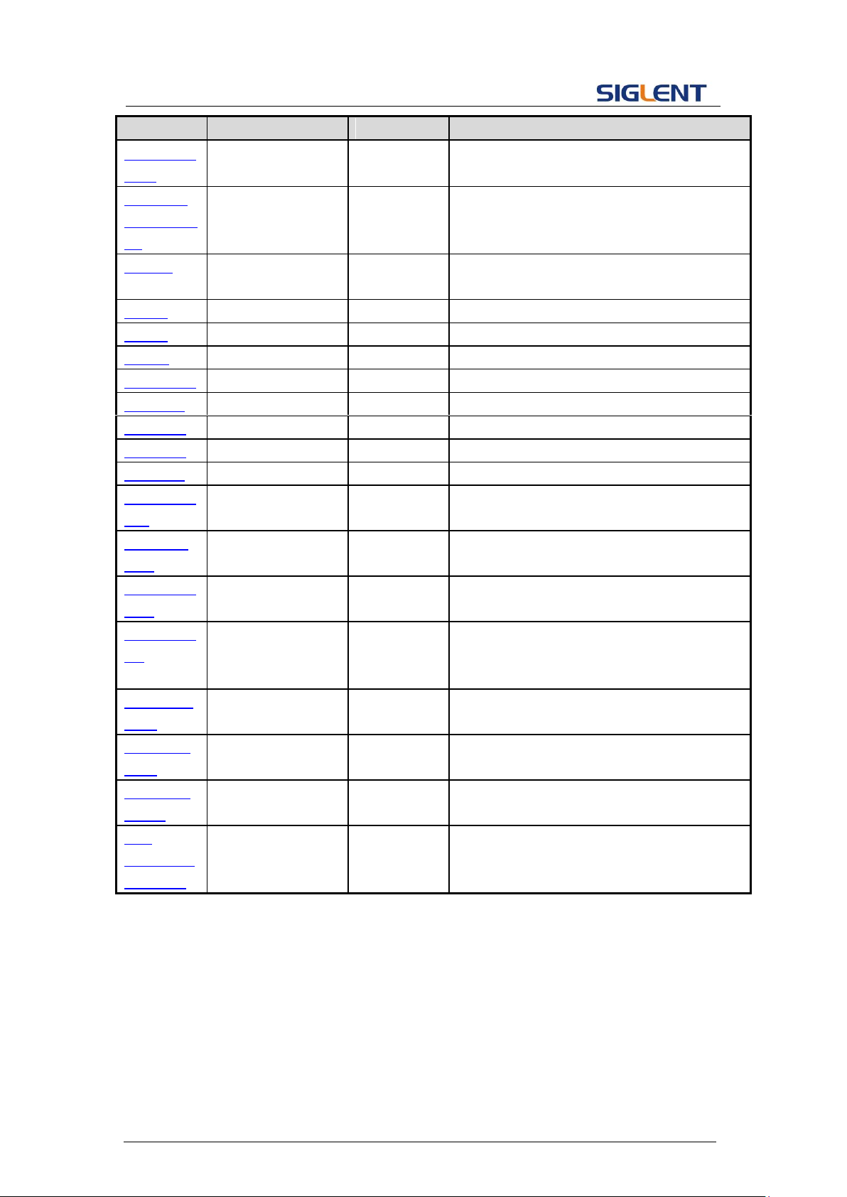
2.5 TABLE OF COMMAND & QUERIES ................................................................................................... 12
3 COMMANDS AND QUERIES ............................................................................................... 14
3.1 IEEE 488.2 COMMON COMMAND INTRODUCTION ........................................................................... 14
3.1.1 *IDN ..................................................................................................................................... 14
3.1.2 *OPC .................................................................................................................................... 15
3.1.3 *RST ..................................................................................................................................... 16
3.2 COMM_HEADER COMMAND ........................................................................................................ 16
3.3 OUTPUT COMMAND .................................................................................................................... 17
3.4 BASIC WAVE COMMAND .............................................................................................................. 18
3.5 MODULATE WAVE COMMAND ...................................................................................................... 21
3.6 SWEEP WAVE COMMAND............................................................................................................. 25
3.7 BURST WAVE COMMAND ............................................................................................................. 27
3.8 PARAMETER COPY COMMAND ....................................................................................................... 30
3.9 ARBITRARY WAVE COMMAND ....................................................................................................... 30
3.10 SYNC COMMAND ........................................................................................................................ 32
3.11 NUMBER FORMAT COMMAND....................................................................................................... 33
3.12 LANGUAGE COMMAND ................................................................................................................ 33
3.13 CONFIGURATION COMMAND ......................................................................................................... 34
3.14 BUZZER COMMAND ..................................................................................................................... 34
3.15 SCREEN SAVE COMMAND ............................................................................................................. 35
3.16 CLOCK SOURCE COMMAND ........................................................................................................... 35
3.17 FREQUENCY COUNTER COMMAND ................................................................................................. 36
3.18 INVERT COMMAND ..................................................................................................................... 37
3.19 COUPLING COMMAND ................................................................................................................. 38
1
Page 3

Programming Guide
3.20 OVER-VOLTAGE PROTECTION COMMAND ........................................................................................ 39
3.21 STORE LIST COMMAND ................................................................................................................ 40
3.22 ARB DATA COMMAND ................................................................................................................. 42
3.23 VIRTUAL KEY COMMAND .............................................................................................................. 44
3.24 IP COMMAND ............................................................................................................................ 46
3.25 SUBNET MASK COMMAND ........................................................................................................... 47
3.26 GATEWAY COMMAND .................................................................................................................. 48
3.27 SAMPLING RATE COMMAND ......................................................................................................... 48
3.28 HARMONIC COMMAND ................................................................................................................ 49
3.29 WAVEFORM COMBINING COMMAND .............................................................................................. 50
3.30 MODE SELECT COMMAND ............................................................................................................ 51
3.31 MULTI-DEVICE SYNC ................................................................................................................... 51
3.32 IQ COMMANDS .......................................................................................................................... 52
3.32.1 :IQ:CENTerfreq ..................................................................................................................... 52
3.32.2 :IQ:SAMPlerate .................................................................................................................... 53
3.32.3 :IQ:SYMBolrate .................................................................................................................... 53
3.32.4 :IQ:AMPLitude ...................................................................................................................... 53
3.32.5 :IQ:IQADjustment:GAIN ....................................................................................................... 54
3.32.6 :IQ:IQADjustment:IOFFset .................................................................................................... 54
3.32.7 :IQ:IQADjustment:QOFFset .................................................................................................. 55
3.32.8 :IQ:IQADjustment:QSKew..................................................................................................... 55
3.32.9 :IQ:TRIGger:SOURce ............................................................................................................. 55
3.32.10 :IQ:WAVEload:BUILtin ...................................................................................................... 56
3.32.11 :IQ:WAVEload:USERstored ............................................................................................... 56
4 PROGRAMMING EXAMPLES ............................................................................................. 58
4.1 EXAMPLES OF USING VISA ........................................................................................................... 58
4.1.1 VC++ Example ...................................................................................................................... 58
4.1.2 VB Example .......................................................................................................................... 65
4.1.3 MATLAB Example ................................................................................................................. 70
4.1.4 LabVIEW Example ................................................................................................................ 72
4.1.5 Python Example ................................................................................................................... 74
4.2 EXAMPLES OF USING SOCKETS ....................................................................................................... 77
4.2.1 Python Example ................................................................................................................... 77
5 INDEX ..................................................................................................................................... 80
2
Page 4

Programming Guide
1 Programming Overview
By using USB and LAN interfaces, in combination with NI-VISA and programming
languages, users can remotely control the waveform generator. Through LAN interface,
VXI-11, Sockets and Telnet protocols can be used to communicate with the instruments.
This chapter introduces how to build communication between the instrument and the PC.
It also introduces how to configure a system for remote instrument control.
1.1 Build communication via VISA
1.1.1 Install NI-VISA
Before programming, please make sure that you have properly installed the latest version
of National Instruments NI-VISA Software.
NI-VISA is a communication library that enables computer communications to
instrumentation. There are two available VISA packages: A full version and the Run-Time
Engine. The full version includes NI device drivers and a tool named NI MAX; a user
interface to control the device. While the drivers and NI MAX can be useful, they are not
required for remote control. The Run-Time Engine is a much smaller file and is
recommended for remote control.
For convenience, you can obtain the latest version of the NI-VISA run-time engine or full
version from the National Instruments website. The installation process is similar for both
versions.
Follow these steps to install NI-VISA (The full version of NI-VISA 5.4 is used in this
example):
a. Download the appropriate version of NI-VISA (the Run-time engine is recommended)
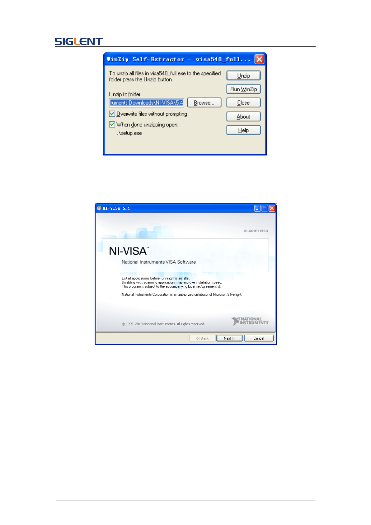
b. Double click the visa540_full.exe, dialog shown as below:
3
Page 5
Programming Guide
c. Click Unzip, the install process will launch after unzipping files. If your computer
needs to install the .NET Framework 4, it may auto start.
d. The NI-VISA install dialog is shown above. Click Next to start the installation process.
4
Page 6
Programming Guide
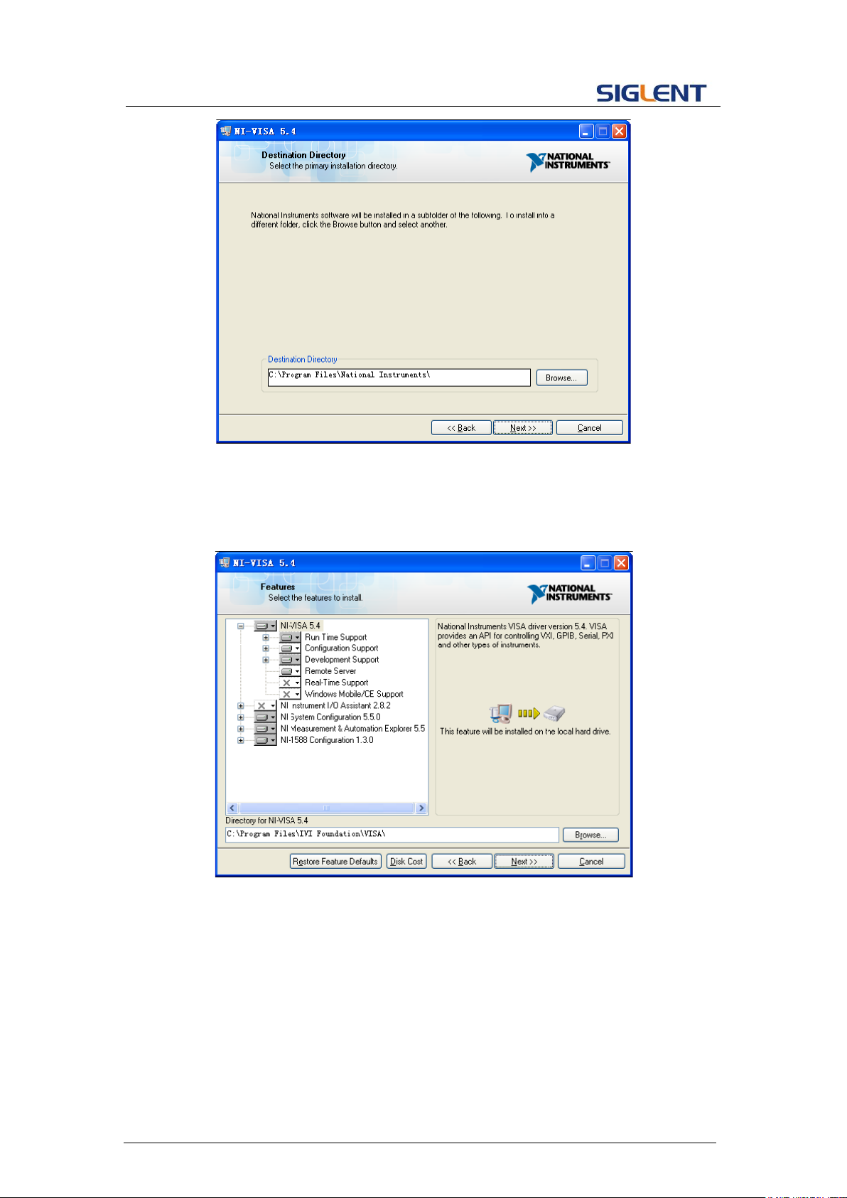
e. Set the install path, default path is “C:\Program Files\National Instruments\”, you can
change it, if you prefer. Click Next, dialog as shown above.
f. Click Next twice, in the License Agreement dialog, select the “I accept the above 2
License Agreement(s).”,and click Next, dialog as shown below:
5
Page 7
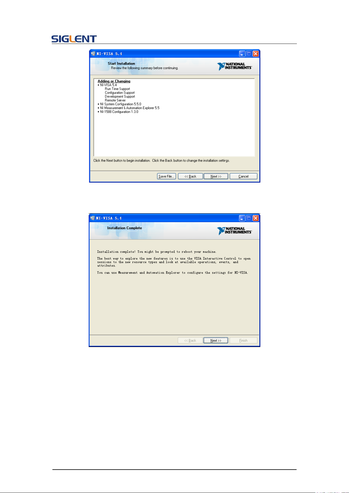
g. Click Next to begin installation.
Programming Guide
h. Now the installation is complete. Reboot your PC.
6
Page 8
Programming Guide
1.1.2 Connect the instrument
Depending on the specific model, the arbitrary waveform generator may be able to
communicate with a PC through the USB or LAN interface.
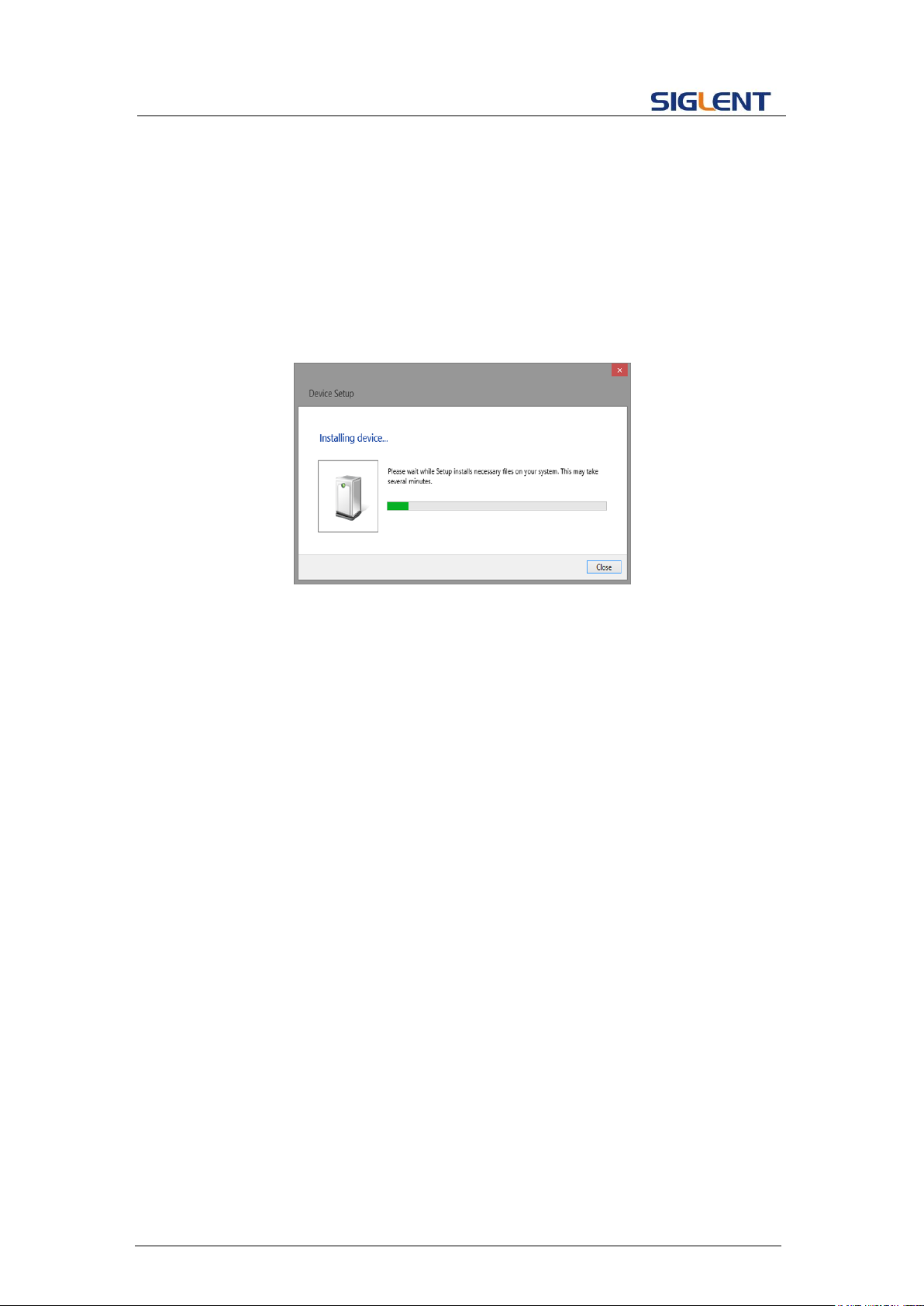
Connect the arbitrary waveform generator and the USB Host interface of the PC using a
USB cable. Assuming your PC is already turned on, turn on the SDG, and then the PC will
display the “Device Setup” screen as it automatically installs the device driver as shown
below.
Wait for the installation to complete and then proceed to the next step.
7
Page 9

Programming Guide
1.2 Remote Control
1.2.1 User-defined Programming
Users can send SCPI commands via a computer to program and control the arbitrary
waveform generator. For details, refer to the introductions in " Programming Examples".
1.2.2 Using SCPI via NI-MAX
NI-MAX is a program created and maintained by National Instruments. It provides a basic
remote control interface for VXI, LAN, USB, GPIB, and Serial communications. The SDG
can be controlled remotely by sending SCPI commands via NI-MAX.
1.2.3 Using SCPI over Telnet
Telnet provides a means of communicating with the SDG over the LAN. The Telnet protocol
sends SCPI commands to the SDG from a PC and is similar to communicating with the
SDG over USB. It sends and receives information interactively: one command at a time.
The Windows operating systems use a command prompt style interface for the Telnet client.
The steps are as follows:
1. On your PC, click Start > All Programs > Accessories > Command Prompt.
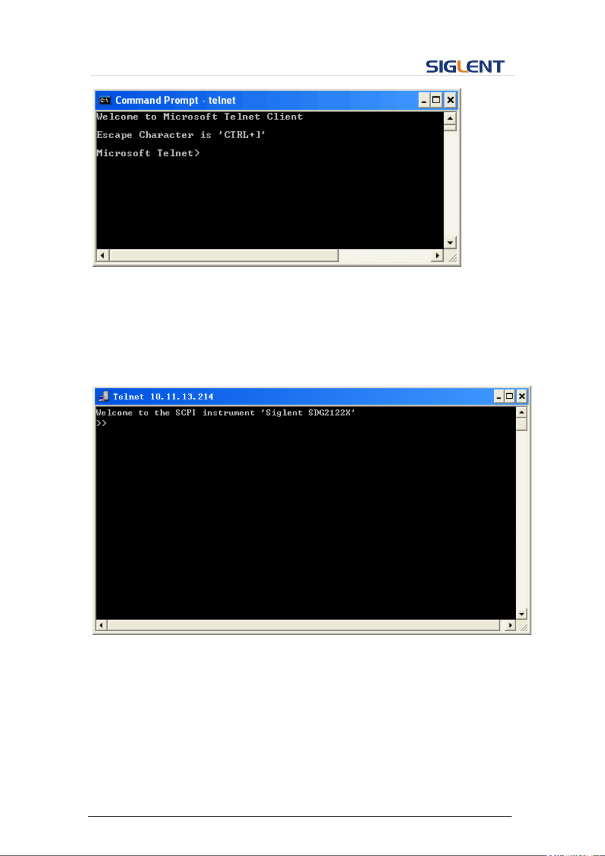
2. At the command prompt, type in telnet.
3. Press the Enter key. The Telnet display screen will be displayed.
8
Page 10
Programming Guide
4. At the Telnet command line, type:
open XXX.XXX.XXX.XXX 5024
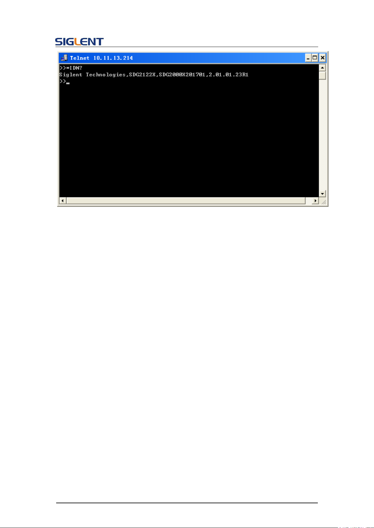
Where XXX.XXX.XXX.XXX is the instrument’s IP address and 5024 is the port. You should
see a response similar to the following:
5. At the SCPI> prompt, input the SCPI commands such as *IDN? to return the company
name, model number, serial number, and firmware version number.
9
Page 11
Programming Guide
6. To exit the SCPI> session, press the Ctrl+] keys simultaneously.
7. Type quit at the prompt or close the Telnet window to close the connection to the
instrument and exit Telnet.
1.2.4 Using SCPI over Socket
Socket API can be used to control the SDG series by LAN without installing any other
libraries. This can reduce the complexity of programming.
SOCKET ADDRESS IP address + port number
IP ADDRESS SDG IP address
PORT NUMBER 5025
Please see section 4.2 "Examples of Using Sockets" for the details.
10
Page 12

Programming Guide
2 Introduction to the SCPI Language
2.1 About Commands & Queries
This section lists and describes the remote control commands and queries recognized by
the instrument. All commands and queries can be executed in either local or remote state.
Each command or query, with syntax and other information, has some examples listed.
The commands are given in both long and short format at “COMMAND SYNTAX”and
“QUERY SYNTAX”, and the subject is indicated as a command or query or both. Queries
perform actions such as obtaining information, and are recognized by the question mark
(?) following the header.
2.2 Description
In the description, a brief explanation of the function performed is given. This is followed
by a presentation of the formal syntax, with the header given in Upper-and-Lower-Case
characters and the short form derived from it in ALL UPPER-CASE characters. Where
applicable, the syntax of the query is given with the format of its response.
2.3 Usage
The commands and queries listed here can be used for SDGxxxx Series Arbitrary
Waveform Generators.
2.4 Command Notation
The following notations are used in the commands:
< > Angular brackets enclose words that are used as placeholders, of which there are
two types: the header path and the data parameter of a command.
:= A colon followed by an equals sign separates a placeholder, from the description of
the type and range of values that may be used in a command instead of the
placeholder.
{ } Braces enclose a list of choices, one of which must be made.
[ ] Square brackets enclose optional items.
… An ellipsis indicates that the items both to its left and right may be repeated for a
11
Page 13
number of times.
Short
Long Form
Subsystem
What Command/Query does
*IDN
*IDN
SYSTEM
Gets identification from device.
*OPC
*OPC
SYSTEM
Gets or sets the OPC bit (0) in the Event
Status Register (ESR).
*RST
*RST
SYSTEM
Initiates a device reset.
CHDR
COMM_HEADER
SIGNAL
Sets or gets the command returned format
OUTP
OUTPUT
SIGNAL
Sets or gets the output state.
BSWV
BASIC_WAVE
SIGNAL
Sets or gets the basic wave parameters.
MDWV
MODULATEWAVE
SIGNAL
Sets or gets the modulation parameters.
SWWV
SWEEPWAVE
SIGNAL
Sets or gets the sweep parameters.
BTWV
BURSTWAVE
SIGNAL
Sets or gets the burst parameters.
PACP
PARACOPY
SIGNAL
Copies parameters from one channel to the
other.
ARWV
ARBWAVE
DATA
Changes arbitrary wave type.
SYNC
SYNC
SIGNAL
Sets or gets the synchronization signal.
NBFM
NUMBER_FORM
AT
SYSTEM
Sets or gets the data format.
LAGG
LANGUAGE
SYSTEM
Sets or gets the language.
SCFG
SYS_CFG
SYSTEM
Sets or gets the power-on system setting
way.
BUZZ
BUZZER
SYSTEM
Sets or gets the buzzer state.
SCSV
SCREEN_SAVE
SYSTEM
Sets or gets the screen save state.
ROSC
ROSCILLATOR
SIGNAL
Sets or gets the state of clock source.
FCNT
FREQCOUNTER
SIGNAL
Sets or gets the frequency counter
parameters.
INVT
INVERT
SIGNAL
Sets or gets the polarity of current channel.
COUP
COUPLING
SIGNAL
Sets or gets the coupling parameters.
VOLTPRT
VOLTPRT
SYSTEM
Sets or gets the state of over-voltage
protection.
STL
STORELIST
SIGNAL
Lists all stored waveforms.
WVDT
WVDT
SIGNAL
Sets and gets the arbitrary wave data.
VKEY
VIRTUALKEY
SYSTEM
Sets the virtual keys.
SYST:CO
MM:LAN:I
PAD
SYSTEM:COMMU
NICATE:LAN:IPAD
DRESS
SYSTEM
The Command can set and get system IP
address.
SYST:CO
SYSTEM:COMMU
SYSTEM
The Command can set and get system
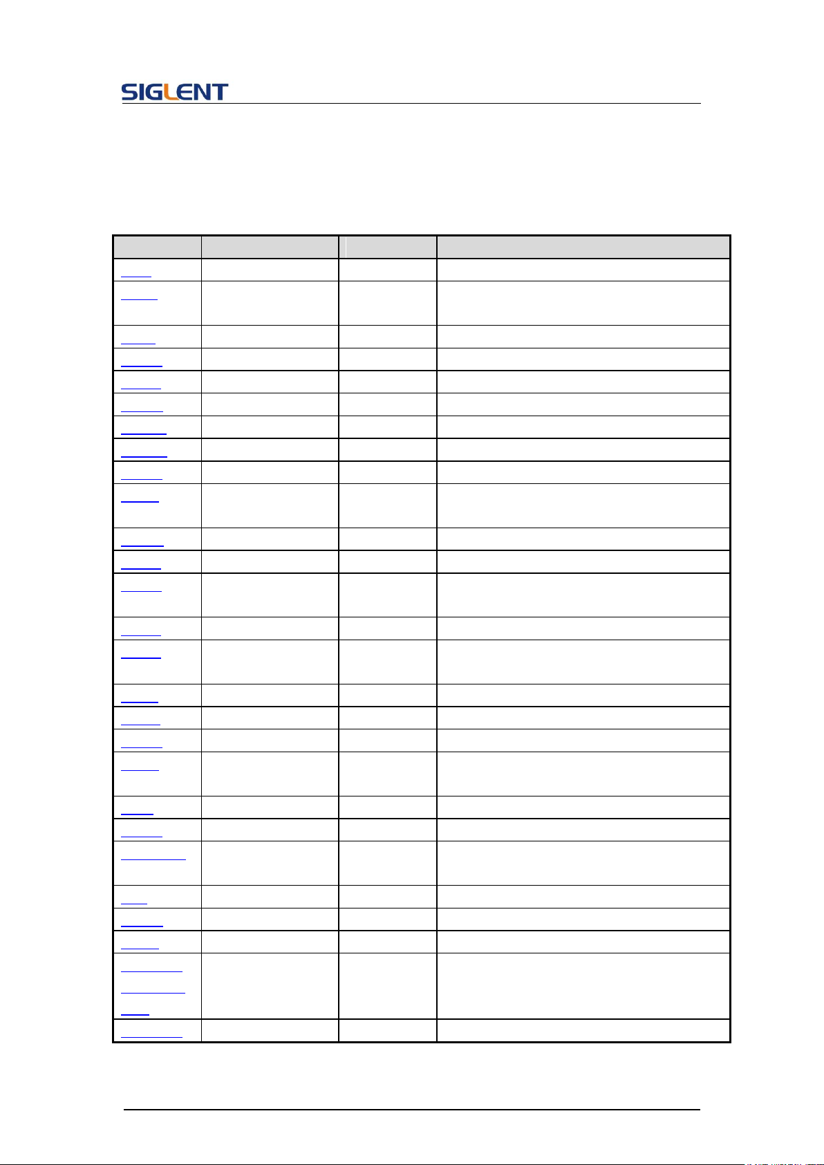
2.5 Table of Command & Queries
Programming Guide
12
Page 14
Programming Guide
Short
Long Form
Subsystem
What Command/Query does
MM:LAN:S
MAS
NICATE:LAN:SMA
SK
subnet mask.
SYST:CO
MM:LAN:G
AT
SYSTEM:COMMU
NICATE:LAN:GAT
EWAY
SYSTEM
The Command can set and get system
Gateway.
SRATE
SAMPLERATE
SIGNAL
Sets or gets the arbitrary wave mode,
sampling rate and interpolation method.
HARM
HARMonic
SIGNAL
Sets or gets the harmonic information.
CMBN
CoMBiNe
SIGNAL
Sets or gets the wave combine information.
MODE
MODE
SIGNAL
Sets or gets the waveform phase mode
CASCADE
CASCADE
SYSTEM
Set up multi-device synchronization
IQ:CENT
IQ:CENTerfreq
SIGNAL
Sets the I/Q modulator center frequency.
IQ:SAMP
IQ:SAMPlerate
SIGNAL
Sets the I/Q sample rate.
IQ:SYMB
IQ:SYMBolrate
SIGNAL
Sets the I/Q symbol rate.
IQ:AMPL
IQ:AMPLitude
SIGNAL
Sets the I/Q amplitude.
IQ:IQAD:G
AIN
IQ:IQADjustment:
GAIN
SIGNAL
Adjusts the ratio of I to Q while preserving
the composite.
IQ:IQAD:I
OFF
IQ:IQADjustment:I
OFFset
SIGNAL
Adjusts the I channel offset value.
IQ:IQAD:Q
OFF
IQ:IQADjustment:
QOFFset
SIGNAL
Adjusts the I channel offset value.
IQ:IQAD:Q
SK
IQ:IQADjustment:
QSKew
SIGNAL
Adjusts the phase angle between the I
and Q vectors by increasing or decreasing
the Q phase angle.
IQ:TRIG:S
OUR
IQ:TRIGger:SOUR
ce
SIGNAL
Sets the I/Q trigger source.
IQ:WAVE:
BUIL
IQ:WAVEload:BUI
Ltin
SIGNAL
Selects the I/Q wave from built in wave list.
IQ:WAVE:
USER
IQ:WAVEload:USE
Rstored
SIGNAL
Select the I/Q wave from user stored
waveforms.
:IQ:
Frequency
Sampling
:IQ:
FrequencySamplin
g
SIGNAL
Sets the I/Q Frequency sampling rate.
13
Page 15

Programming Guide
DESCRIPTION
The *IDN? query causes the instrument to identify itself. The
response is comprised of the manufacturer, model, serial number
and firmware version.
QUERY SYNTAX
*IDN?
RESPONSE FORMAT
Format 1: *IDN, <device id>,<model>,<serial number>,<firmware
version>, <hardware version>
Format 2: <manufacturer>,<model>,<serial number>,<firmware
version>
<device id>:= “SDG”.
<manufacturer>:= “Siglent Technologies”.
<model>:= A model identifier less than 14 characters, should not
contain the word “MODEL”.
<serial number>:= The serial number.
<firmware version>:= The firmware version number.
<hardware version>:= The hardware level field, containing
information about all separately revisable subsystems.
EXAMPLE
Reads version information:
*IDN?
Return:
Siglent Technologies,SDG6052X, SDG6XBAX1R0034,
6.01.01.28 (It may differ from each version)
3 Commands and Queries
3.1 IEEE 488.2 Common Command Introduction
The IEEE standard defines the common commands used for
querying the basic information of the instrument or executing
basic operations. These commands usually start with "*" and
the length of the keywords of the command is usually 3
characters.
3.1.1 *IDN
Notes:
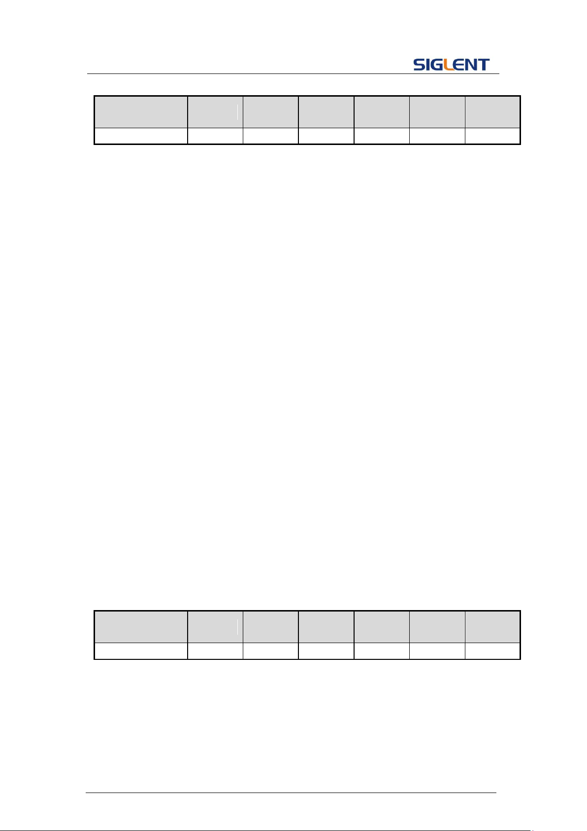
1. The table below shows the available response format of the command in each SDG
14
Page 16
Programming Guide
Parameter
/command
SDG800
SDG1000
SDG2000X
SDG5000
SDG1000X
SDG6000X
/X-E
Response Format
Format1
Format1
Format2
Format1
Format2
Format2
DESCRIPTION
The *OPC (Operation Complete) command sets the OPC bit (bit
0) in the standard Event Status Register (ESR). This command
has no other effect on the operation of the device because the
instrument starts parsing a command or query only after it has
completely processed the previous command or query. The
*OPC? query always responds with the ASCII character 1
because the device only responds to the query when the previous
command has been entirely executed.
COMMAND SYNTAX
*OPC
QUERY SYNTAX
*OPC?
RESPONSE FORMAT
Format 1: *OPC 1
Format 2: 1
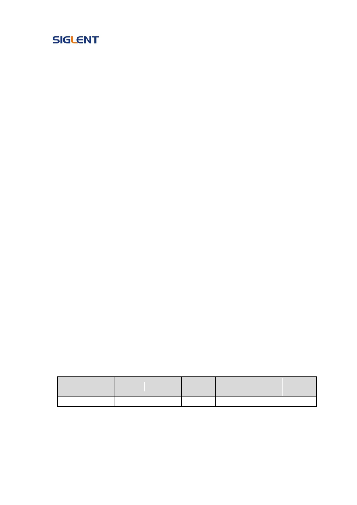
Parameter
/command
SDG800
SDG1000
SDG2000X
SDG5000
SDG1000X
SDG6000X
/X-E
Response Format
Format1
Format1
Format2
Format1
Format2
Format2
series.
2. Format of <hardware version>: value1-value2-value3-value4-value5.
value1: PCB version.
value2: Hardware version.
value3: Hardware subversion.
value4: FPGA version.
value5: CPLD version.
3.1.2 *OPC
Note: The table below shows the available response format of the command in each SDG
series.
15
Page 17
3.1.3 *RST
DESCRIPTION
The *RST command initiates a device reset and recalls the
default setup.
COMMAND SYNTAX
*RST
EXAMPLE
This example resets the signal generator to the default setup:
*RST
DESCRIPTION
This command is used to change the query command returned
format. “SHORT” parameter returns short format. “LONG”
parameter returns long format. “OFF” returns nothing.
COMMAND SYNTAX
Comm_HeaDeR <parameter>
<parameter>:= {SHORT,LONG,OFF}.
QUERY SYNTAX
Comm_HeaDeR?
RESPONSE FORMAT
CHDR <parameter>
EXAMPLE
Set query command format to long:
CHDR LONG
Read query command format:
CHDR?
Return:
COMM_HEADER LONG
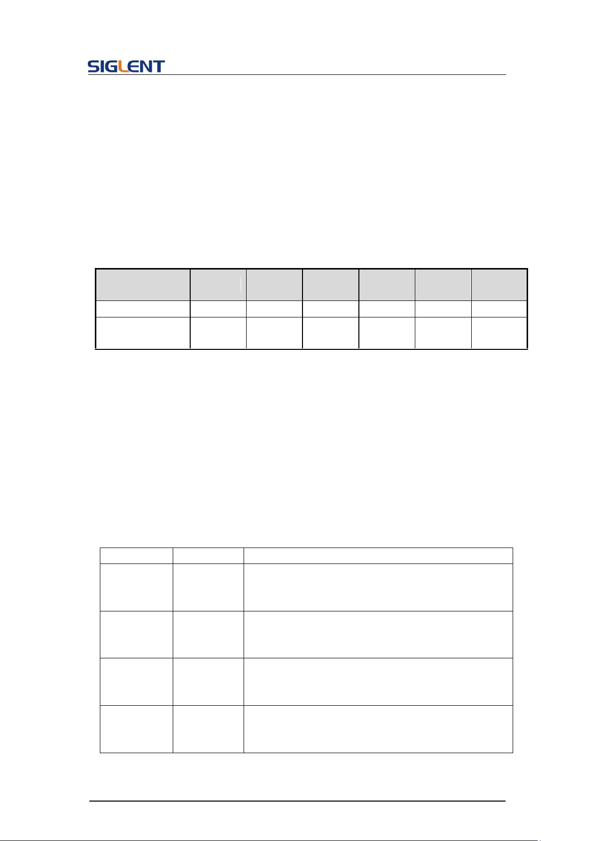
Parameter
/command
SDG800
SDG1000
SDG2000X
SDG5000
SDG1000X
SDG6000X
/X-E
CHDR
yes
yes
no
yes
no
no
3.2 Comm_Header Command
Programming Guide
Note: The table below shows the availability of the command in each SDG series.
16
Page 18

Programming Guide
DESCRIPTION
This command enables or disables the output port(s) at the front panel. The query returns
“ON” or “OFF” and “LOAD”, “PLRT”, “RATIO” parameters.
COMMAND
SYNTAX
<channel>:OUTPut ON|OFF,LOAD,<load>,PLRT, <polarity>
<channel>:= {C1, C2}.
<load>:= {see the note below}. The unit is ohm.
<polarity>:= {NOR, INVT}, in which NOR refers to normal, and INVT refers to invert.
NoiseSum: to add noise to the channel with specified signal-to-noise ratio.
<channel>:NOISE_ADD STATE,ON|OFF,RATIO,<S/N>.
or
<channel>:NOISE_ADD STATE,ON|OFF,RATIO_DB,<S/N(dB)>.
<S/N>:= {2.1-100000000}.
<S/N (dB)>:= {3.24886-80}.
Max Amplitude Output: to limit the maximum amplitude output.
<channel>:BSWV MAX_OUTPUT_AMP, <Amplitude>
<Amplitude>:={1-20}, Maximum output amplitude peak-to-peak voltages.
QUERY
SYNTAX
<channel>:OUTPut?
<channel>:NOISE_ADD?
<channel>:BSWV?
RESPONSE
FORMAT
<channel>:OUTP ON|OFF,LOAD,<load>,PLRT, <polarity>
<channel>:NOISE_ADDSTATE,ON|OFF,RATIO,<S/N >,RATIO_DB,<S/N (dB)>
<channel>:BSWV WVTP,<type>,FRQ,
<frequency>,PERI,<period>,AMP,<amplitude>,AMPVRMS,<Amplitude>,MAX_OUTPUT
_AMP, OFST, <offset>, HLEV, <high level>, LLEV, <low level>, PHSE, <phase>
EXAMPLE
Turn on CH1:
C1:OUTP ON
Read CH1 output state:
C1:OUTP?
Return:
C1:OUTP ON,LOAD,HZ,PLRT,NOR
Set the load of CH1 to 50 ohm:
C1:OUTP LOAD,50
Set the load of CH1 to HiZ:
3.3 Output Command
17
Page 19
Programming Guide
C1:OUTP LOAD,HZ
Set the polarity of CH1 to normal:
C1:OUTP PLRT,NOR
turn on NoiseSum and set the signal-to-noise ratio
C1:NOISE_ADD STATE,ON,RATIO,120
Set the maximum output amplitude
C1:BSWV MAX_OUTPUT_AMP,5
Parameter
/command
SDG800
SDG1000
SDG2000X
SDG5000
SDG1000X
SDG6000X
/X-E
<channel>
no
yes
yes
yes
yes
yes
LOAD
50, HZ
50~10000,
HZ
50~100000
, HZ
50, HZ
50~100000
, HZ
50~100000
, HZ
DESCRIPTION
This command sets or gets the basic wave parameters.
COMMAND SYNTAX
<channel>:BaSic_WaVe <parameter>,<value>
<channel>:={C1, C2}.
<parameter>:= {a parameter from the table below}.
<value>:={value of the corresponding parameter}.
Parameters
Value
Description
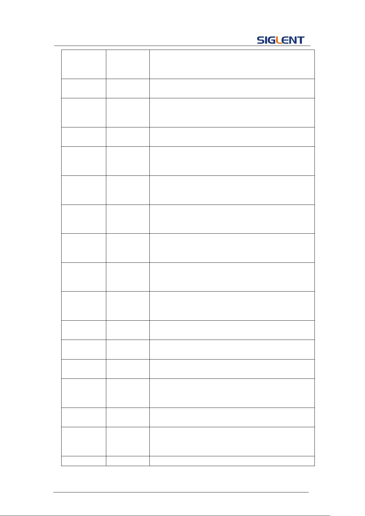
WVTP
<type>
:= {SINE, SQUARE, RAMP, PULSE, NOISE, ARB, DC,
PRBS, IQ}. If the command doesn’t set basic waveform
type, WVPT will be set to the current waveform.
FRQ
<frequency>
:= frequency. The unit is Hertz “Hz”. Refer to the data
sheet for the range of valid values. Not valid when WVTP
is NOISE or DC.
PERI
<period>
:= period. The unit is seconds "s". Refer to the data sheet
for the range of valid values. Not valid when WVTP is
NOISE or DC.
AMP
<amplitude>
:= amplitude. The unit is volts, peak-to-peak "Vpp". Refer
to the data sheet for the range of valid values. Not valid
when WVTP is NOISE or DC.
Note: The table below shows the availability of the command in each SDG series.
* "HZ" refers to High Z.
3.4 Basic Wave Command
18
Page 20
Programming Guide
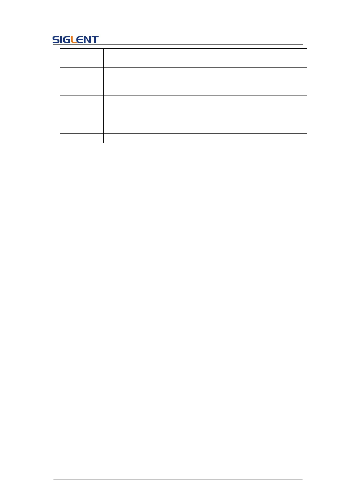
OFST
<offset>
:= offset. The unit is volts "V". Refer to the data sheet for
the range of valid values. Not valid when WVTP is
NOISE.
SYM
<symmetry>
:={0 to 100}. Symmetry of RAMP. The unit is "%". Only
settable when WVTP is RAMP.
DUTY
<duty>
:= {0 to 100}. Duty cycle. The unit is "%". Value depends
on frequency. Only settable when WVTP is SQUARE or
PULSE.
PHSE
<phase>
:= {0 to 360}. The unit is "degree". Not valid when WVTP
is NOISE, PULSE or DC.
STDEV
<stdev>
:= standard deviation of NOISE. The unit is volts "V".
Refer to the data sheet for the range of valid values. Only
settable when WVTP is NOISE.
MEAN
<mean>
:= mean of NOISE. The unit is volts "V". Refer to the data
sheet for the range of valid values. Only settable when
WVTP is NOISE.
WIDTH
<width>
:= positive pulse width. The unit is seconds "s". Refer to
the data sheet for the range of valid values. Only settable
when WVTP is PULSE.
RISE
<rise>
:= rise time (10%~90%). The unit is seconds "s". Refer
to the data sheet for the range of valid values. Only
settable when WVTP is PULSE.
FALL
<fall>
:= fall time (90%~10%). The unit is seconds "s". Refer to
the data sheet for the range of valid values. Only settable
when WVTP is PULSE.
DLY
<delay>
:= pulse delay. The unit is seconds "s". Refer to the data
sheet for the range of valid values. Only settable when
WVTP is PULSE.
HLEV
<high level>
:= high level. The unit is volts "V". Not valid when WVTP
is NOISE or DC.
LLEV
<low level>
:= low level. The unit is volts "V". Not valid when WVTP
is NOISE or DC.
BANDSTATE
<bandwidth
switch >
:= {ON,OFF}. Only settable when WVTP is NOISE.
BANDWIDT
H
<bandwidth
value>
:= noise bandwidth. The unit is Hertz "Hz". Refer to the
data sheet for the range of valid values. Only settable
when WVTP is NOISE.
LENGTH
<prbs
length>
:={3~32}. Actual PRBS length = 2
LENGTH
-1. Only settable
when WVTP is PRBS.
EDGE
<prbs
rise/fall>
:= rise/fall time of PRBS. The unit is seconds "s". Refer
to the data sheet for the range of valid values. Only
settable when WVTP is PRBS.
DIFFSTATE
<prbs
:={ON, OFF}. State of PRBS differential mode. Only
19
Page 21
Programming Guide
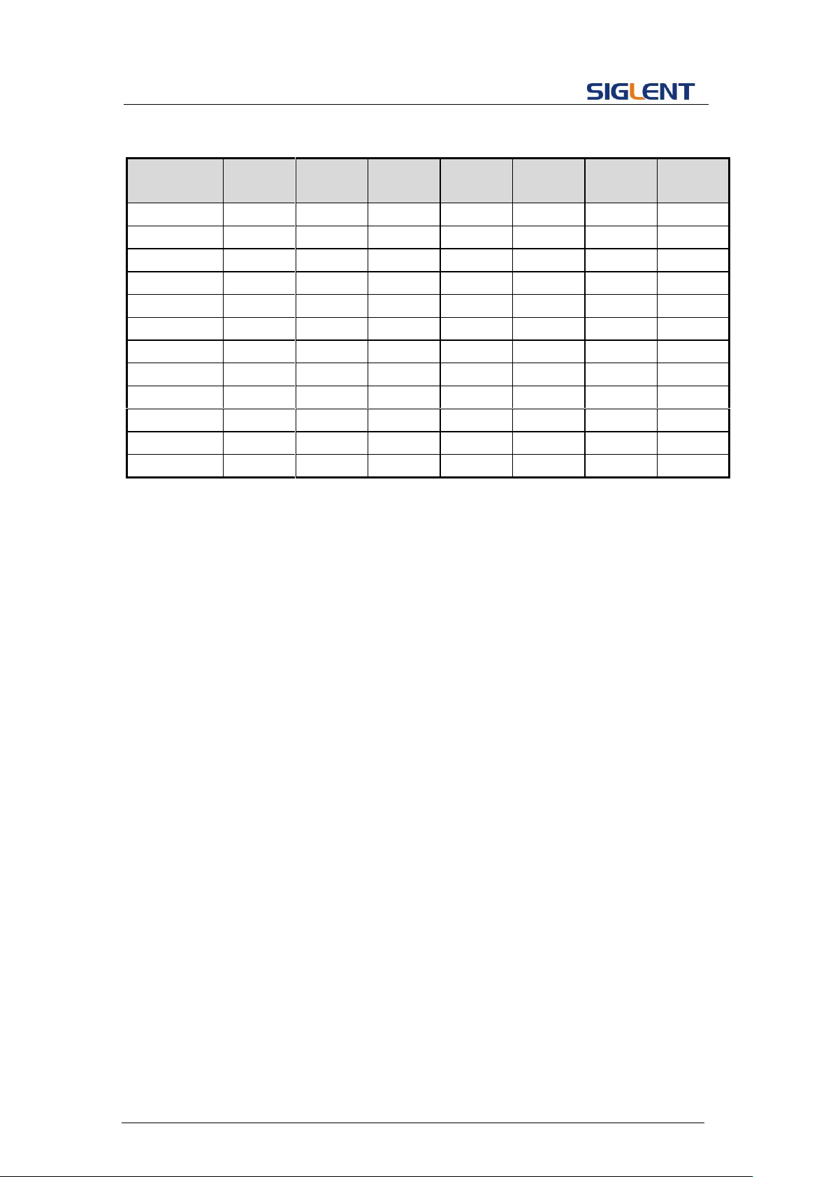
differential
switch>
settable when WVTP is PRBS.
BITRATE
<prbs bit
rate>
:= PRBS bit rate. The unit is bits-per-second "bps". Refer
to the data sheet for the range of valid values. Only
settable when WVTP is PRBS.
LOGICLEVE
L
<prbs
logiclevel
rate>
:={ TTL_CMOS, LVTTL_LVCMOS, ECL, LVPECL,
LVDS }. Only settable when WVTP is PRBS.
AMPVRMS
<amplitude>
:= amplitude. The unit is Vrm.
AMPDBM
<amplitude>
:= amplitude. The unit is dBm.
QUERY SYNTAX
<channel>: BaSic_WaVe?
<channel>:= {C1, C2}.
RESPONSE FORMAT
<channel>:BSWV <parameter>
<parameter>:= {All the parameters of the current basic
waveform}.
EXAMPLE
Change the waveform type of C1 to Ramp:
C1:BSWV WVTP,RAMP
Change the frequency of C1 to 2000 Hz:
C1:BSWV FRQ,2000
Set the amplitude of C1 to 3 Vpp:
C1:BSWV AMP,3
Return parameters of C1 from the device:
C1:BSWV?
Return:
C1:BSWV WVTP,SINE,FRQ,100HZ,PERI,0.01S,AMP,2V,
OFST,0V,HLEV,1V,LLEV,-1V,PHSE,0
Set noise bandwidth of C1 to 100 MHz:
C1:BSWV BANDWIDTH,100E6
or
C1:BSWV BANDWIDTH,100000000
Set output amplitude of C1 to 3dBm:
C1:BSWV AMPDBM,3
Set the logic level of C1 to TTL_CMOS:
C1:BSWV LOGICLEVEL,TTL_CMOS
Notes:
20
Page 22
Programming Guide
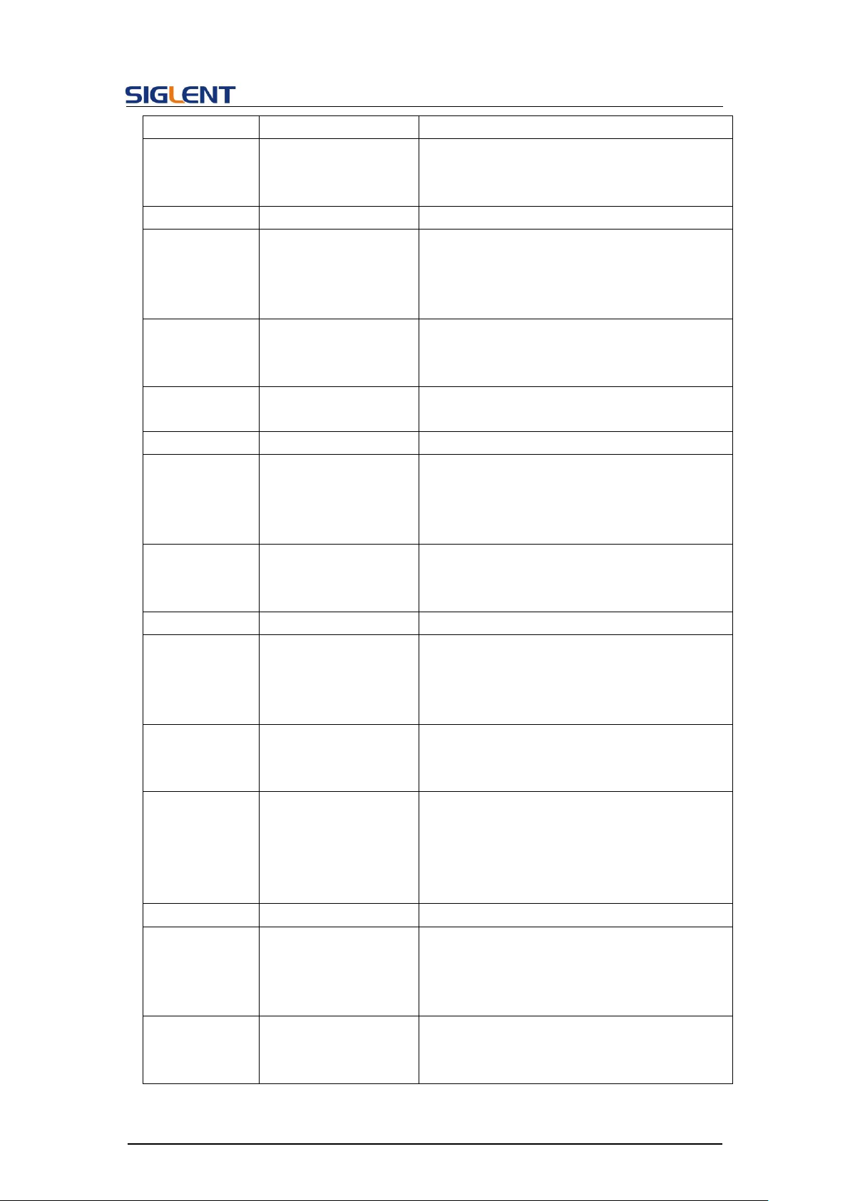
Parameter
/command
SDG800
SDG1000
SDG2000
X
SDG5000
SDG1000
X
SDG6000
X
SDG6000
X-E
<channel>
no
yes
yes
yes
yes
yes
yes
RISE
yes
no
yes
yes
yes
yes
yes
FALL
yes
no
yes
yes
yes
yes
yes
DLY
no
yes
yes
yes
yes
yes
yes
BANDSTATE
no
no
yes
no
no
yes
yes
BANDWIDTH
no
no
yes
no
no
yes
yes
LENGTH
no
no
no
no
no
yes
no
EDGE
no
no
no
no
no
yes
no
DIFFSTATE
no
no
no
no
no
yes
no
BITRATE
no
no
no
no
no
yes
no
LOGICLEVEL
no
no
no
no
no
yes
no
AMPDBM
no
no
yes
no
yes
yes
yes
DESCRIPTION
This commend sets or gets the modulation parameters.
COMMAND SYNTAX
<channel>:MoDulateWaVe <type>
<channel>:MoDulateWaVe <parameter>,<value>
<channel>:={C1, C2}
<type>:= {AM,DSBAM,FM,PM,PWM,ASK,FSK,PSK}.
<parameter>:= {a parameter from the table below}.
<value>:= {value of the corresponding parameter}.
1. The table below shows the availability of some command parameters in each SDG
series.
2. In SDG1000X if Wave Combine is enabled, WVTP cannot be set to SQUARE.
3.5 Modulate Wave Command
21
Page 23
Programming Guide
Parameters
Value
Description
STATE
<state>
:={ON, OFF}. Enable or disable modulation.
STATE must be set to ON before you set or
read other parameters of the modulation.
AM, SRC
<src>
:= {INT, EXT}. AM signal source.
AM, MDSP
<mod wave shape>
:= {SINE, SQUARE, TRIANGLE, UPRAMP,
DNRAMP, NOISE, ARB}.
AM modulation wave. Only settable when
SRC is INT.
AM, FRQ
<AM frequency>
:= AM frequency. The unit is Hertz "Hz". Refer
to the data sheet for the range of valid values.
Only settable when SRC is INT.
AM, DEPTH
<depth>
:= {0 to 120}. AM depth. The unit is "%". Only
settable when SRC is INT.
DSBAM, SRC
<src>
:= {INT, EXT}. DSBAM signal source.
DSBAM,
MDSP
<mod wave shape>
:= {SINE, SQUARE, TRIANGLE, UPRAMP,
DNRAMP, NOISE, ARB}.
DSB AM modulation wave. Only settable
when SRC is INT.
DSBAM, FRQ
<DSB-AM
frequency>
:= DSB AM frequency. The unit is Hertz "Hz".
Refer to the data sheet for the range of valid
values. Only settable when SRC is INT.
FM, SRC
<src>
:= {INT, EXT}. FM signal source.
FM, MDSP
<mod wave shape>
:= {SINE, SQUARE, TRIANGLE, UPRAMP,
DNRAMP, NOISE, ARB}.
FM modulation wave. Only settable when
SRC is INT.
FM, FRQ
<FM frequency>
:= FM frequency. The unit is Hertz "Hz". Refer
to the data sheet for the range of valid values.
Only settable when SRC is INT.
FM, DEVI
<FM frequency
deviation >
:= {0 to carrier frequency}.
FM frequency deviation. The value depends
on the difference between the carrier
frequency and the bandwidth frequency. Only
settable when signal source is INT.
PM, SRC,
<src>
:= {INT, EXT}. PM signal source.
PM, MDSP
<mod wave shape>
:= {SINE, SQUARE, TRIANGLE, UPRAMP,
DNRAMP, NOISE, ARB}.
PM modulation wave. Only settable when
SRC is INT.
PM, FRQ
<PM frequency>
:= PM frequency. The unit is Hertz "Hz". Refer
to the data sheet for the range of valid values.
Only settable when SRC is INT.
22
Page 24
Programming Guide
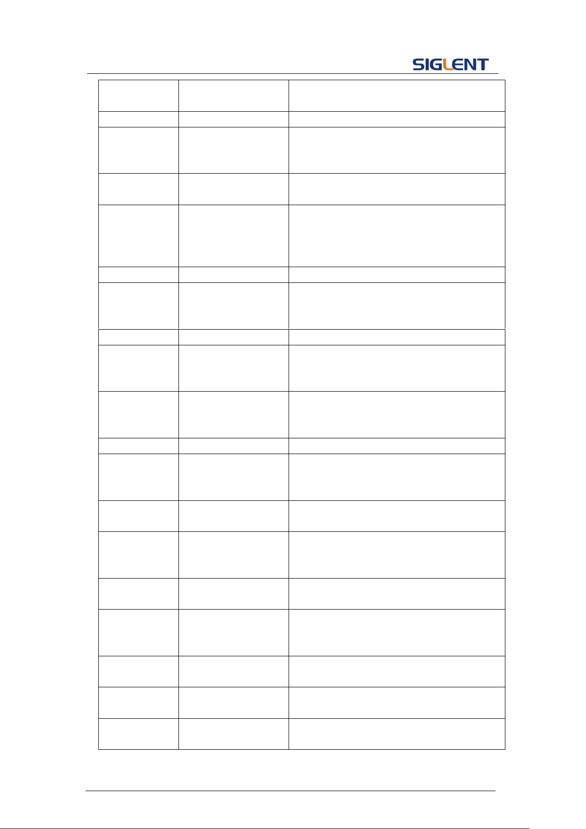
PM, DEVI
<PM phase offset>
:= {0 to 360}. PM phase deviation. The unit is
"degree". Only settable when SRC is INT.
PWM, SRC
<src>
:= {INT, EXT}. PWM signal source.
PWM, FRQ
<PWM frequency>
:= PWM frequency. The unit is Hertz "Hz".
Refer to the data sheet for the range of valid
values. Only settable when SRC is INT.
PWM, DEVI
<PWM dev>
:= Duty cycle deviation. The unit is "%". Value
depends on the carrier duty cycle.
PWM, MDSP
<mod wave shape>
:= {SINE, SQUARE, TRIANGLE, UPRAMP,
DNRAMP, NOISE, ARB}.
PWM modulation wave. Only settable when
SRC is INT.
ASK, SRC
<src>
:= {INT, EXT}. ASK signal source.
ASK, KFRQ
< key frequency>
:= ASK key frequency. The unit is Hertz "Hz".
Refer to the data sheet for the range of valid
values. Only settable when SRC is INT.
FSK, SRC
<src>
:= {INT, EXT}. FSK signal source.
FSK, KFRQ
< key frequency>
:= FSK key frequency. The unit is Hertz "Hz".
Refer to the data sheet for the range of valid
values. Only settable when SRC is INT.
FSK, HFRQ
<FSK_hop_freq>
:= FSK hop frequency. The same with basic
wave frequency. The unit is Hertz "Hz". Refer
to the data sheet for the range of valid values.
PSK, SRC
<src>
:= {INT, EXT}. PSK signal source.
PSK, KFRQ
< key frequency>
:= PSK key frequency. The unit is Hertz "Hz".
Refer to the data sheet for the range of valid
values. Only settable when SRC is INT.
CARR, WVTP
<wave type>
:= {SINE, SQUARE, RAMP, ARB, PULSE}.
Carrier waveform type.
CARR, FRQ
<frequency>
:= carrier frequency. The unit is Hertz "Hz".
Refer to the data sheet for the range of valid
values.
CARR, PHSE
<phase>
:= {0 to 360}. Carrier phase. The unit is
"degree".
CARR, AMP
<amplitude>
:= carrier amplitude. The unit is volts, peakto-peak "Vpp". Refer to the data sheet for the
range of valid values.
CARR, OFST
<offset>
:= carrier offset. The unit is volts "V". Refer to
the data sheet for the range of valid values.
CARR, SYM
<symmetry>
:= {0 to 100}. Carrier symmetry when the
carrier is RAMP. The unit is "%".
CARR, DUTY
<duty>
:= {0 to 100}. Carrier duty cycle when the
carrier is SQUARE or PULSE. The unit is "%".
23
Page 25
Programming Guide
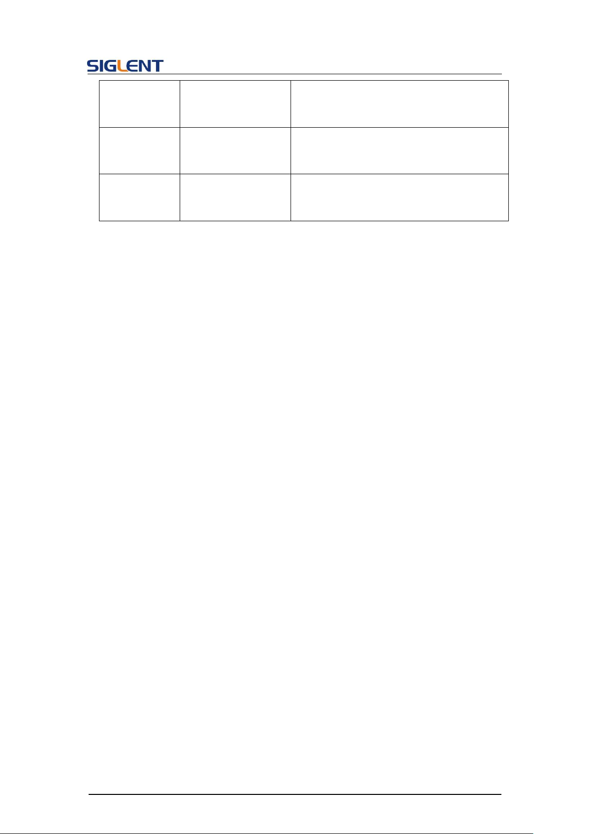
CARR, RISE
<rise>
:= rise time when the carrier is PULSE. The
unit is seconds "s". Refer to the data sheet for
the range of valid values.
CARR, FALL
<fall>
:= fall time when the carrier is PULSE. The
unit is seconds "s". Refer to the data sheet for
the range of valid values.
CARR, DLY
<delay>
:= pulse delay when the carrier is PULSE.
The unit is seconds "s". Refer to the data
sheet for the range of valid values.
Notes:
1. Modulation is not available if the carrier wave is Noise.
2. Range of some parameters depends on the model. Refer to the data sheet for details.
QUERY SYNTAX
<channel>:MoDulateWaVe?
<channel>:={C1, C2}.
RESPONSE FORMAT
<channel>:MDWV <parameter>
<parameter>:= {all parameters of the current modulation}.
EXAMPLE
Set CH1 modulation state to on:
C1:MDWV STATE,ON
Set CH1 modulation type to AM:
C1:MDWV AM
Set modulation to AM, and the modulating wave type to sine
wave:
C1:MDWV AM,MDSP,SINE
Read CH1 modulation parameters when STATE is ON:
C1:MDWV?
Return:
C1:MDWV AM,STATE,ON,MDSP,SINE,SRC,INT,FRQ,100HZ,
DEPTH,100,CARR,WVTP,RAMP,FRQ,1000HZ,AMP,4V,
AMPVRMS,1.15473Vrms,OFST,0V,PHSE,0,SYM,50
Read CH1 modulate wave parameters when STATE is OFF:
C1:MDWV?
Return:
C1:MDWV STATE,OFF
24
Page 26
Programming Guide
Set CH1 FM frequency to 1000 Hz:
C1:MDWV FM,FRQ,1000
Set CH1 carrier to SINE:
C1:MDWV CARR,WVTP,SINE
Set CH1 carrier frequency to 1000 Hz:
C1:MDWV CARR,FRQ,1000
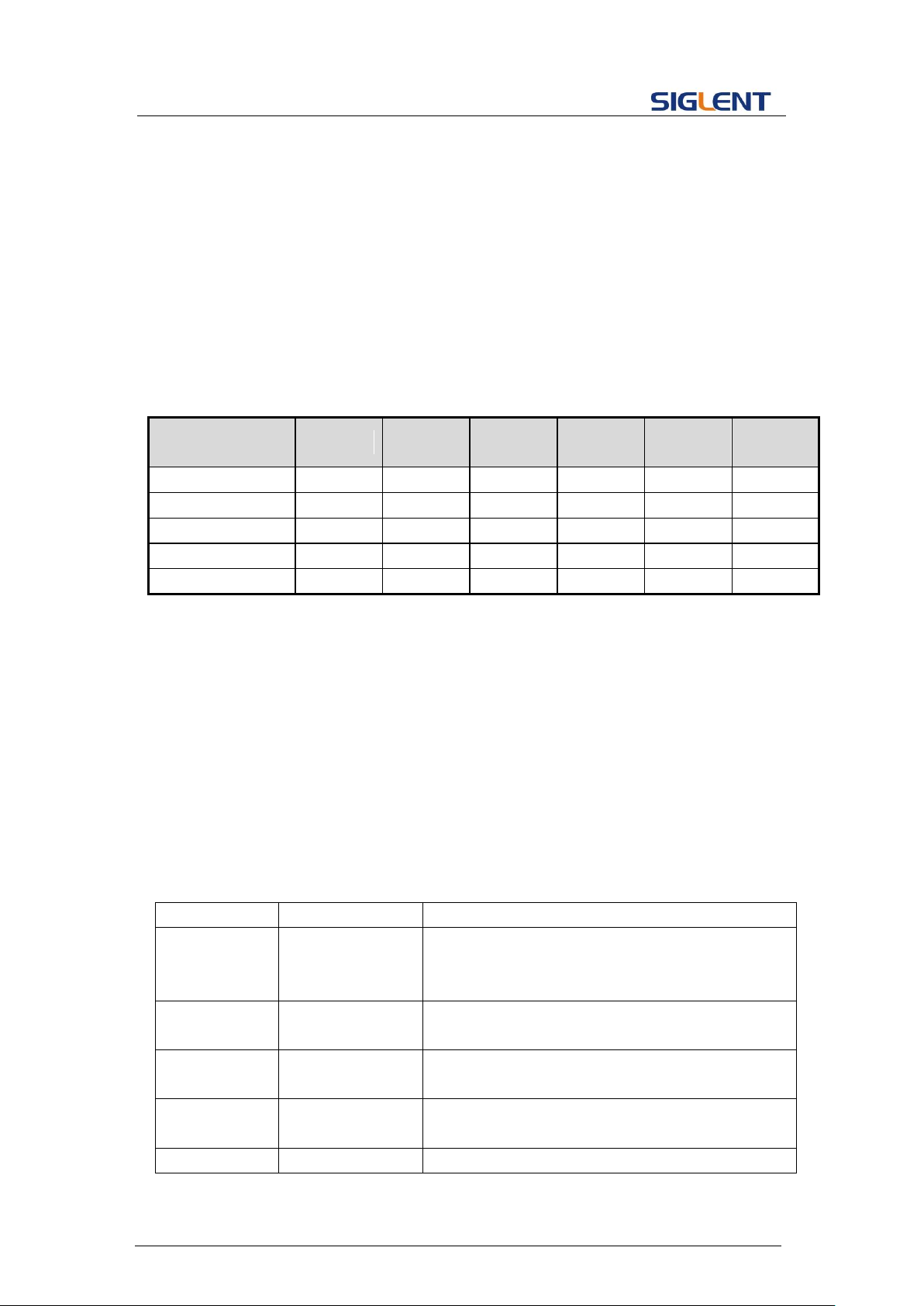
Parameter
/command
SDG800
SDG1000
SDG2000X
SDG5000
SDG1000X
SDG6000X
/X-E
<channel>
no
yes
yes
yes
yes
yes
<type>, SRC
no
yes
yes
yes
yes
yes
CARR, DLY
no
yes
yes
yes
yes
yes
CARR, RISE
yes
no
yes
yes
yes
yes
CARR, FALL
yes
no
yes
yes
yes
yes
DESCRIPTION
This command sets or gets the sweep parameters.
COMMAND SYNTAX
<channel>:SweepWaVe <parameter>,<value>
<channel>:={C1, C2}
<parameter>:= {a parameter from the table below}
<value>:={value of the corresponding parameter}
Parameters
Value
Description
STATE
<state>
:={ON, OFF}. Enable or disable sweep.
STATE must be set to ON before you set or read
other parameters of the sweep.
TIME
<time>
:= sweep time. The unit is seconds "s". Refer to
the data sheet for the range of valid values.
START
<start_freq>
:= start frequency. The same with basic wave
frequency. The unit is Hertz "Hz".
STOP
<stop_freq>
:= stop frequency. The same with basic wave
frequency. The unit is Hertz "Hz".
SWMD
<sweep_mode>
:= {LINE, LOG}, in which LINE refers to Linear and
Note: The table below shows the availability of some command parameters in each SDG
series.
<type>:= {AM, FM, PM, FSK, ASK, PSK, DSBAM, PWM}.
3.6 Sweep Wave Command
25
Page 27
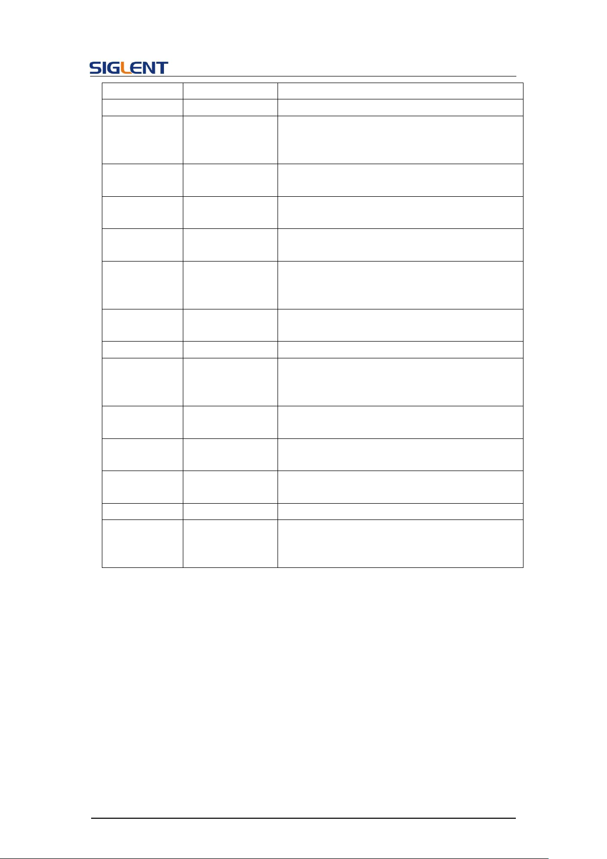
Programming Guide
LOG refers to Logarithmic.
DIR
<direction>
:= {UP, DOWN}. Sweep direction.
TRSR
<trig_src>
:= {EXT, INT, MAN}. Trigger source. EXT refers to
External, INT refers to Internal and MAN refers to
Manual.
MTRIG
:= send a manual trigger. Only valid when TRSR
is MAN.
TRMD
<trig_mode>
:= {ON, OFF}. State of trigger output. If TRSR is
EXT, the parameter is invalid.
EDGE
<edge>
:={RISE, FALL}. Available trigger edge. Only valid
when TRSR is EXT or MAN.
CARR, WVTP
<wave type>
:= {SINE, SQUARE, RAMP, ARB}. Carrier
waveform type. Modulation is not available if the
carrier is PULSE, NOISE or DC.
CARR, FRQ
<frequency>
:= carrier frequency. The unit is Hertz "Hz". Refer
to the data sheet for the range of valid values.
CARR, PHSE
<phase>
:= {0 to 360}. Carrier phase. The unit is "degree".
CARR, AMP
<amplitude>
:= carrier amplitude. The unit is volts, peak-topeak "Vpp". Refer to the data sheet for the range
of valid values.
CARR, OFST
<offset>
:= carrier offset. The unit is volts "V". Refer to the
data sheet for the range of valid values.
CARR, SYM
<symmetry>
:= {0 to 100}. Carrier symmetry when the carrier is
RAMP. The unit is "%".
CARR, DUTY
<duty>
:= {0 to 100}. Carrier duty cycle when the carrier is
SQUARE. The unit is "%".
MARK_STATE
<state>
:= {ON, OFF}.
MARK_FREQ
<frequency>
:= mark frequency. The unit is Hertz "Hz". The
range is from the start frequency to the stop
frequency.
QUERY SYNTAX
<channel>:SWeepWaVe?
<channel>:= {C1, C2}.
RESPONSE FORMAT
<channel>:SWWV <parameter>
<parameter>:= {All parameters of the current sweep wave}
EXAMPLE
Set CH1 sweep state to ON:
C1:SWWV STATE,ON
Set CH1 sweep time to 1 s:
C1:SWWV TIME,1
26
Page 28
Programming Guide
Set CH1 stop frequency to 1000 Hz:
C1:SWWV STOP,1000
Set trigger source of CH1 to Manual:
C1:SWWV TRSR,MAN
Send a manual trigger to CH1:
C1:SWWV MTRIG
Read CH2 sweep parameters when STATE is ON:
C2:SWWV?
Return:
C2:SWWV STATE,ON,TIME,1S,STOP,100HZ,START,100HZ,
TRSR,MAN,TRMD,OFF,SWMD,LINE,DIR,UP,CARR,WVTP,
SQUARE,FRQ,1000HZ,AMP,4V,OFST,0V,DUTY,50,PHSE,0
Read CH2 sweep parameters when STATE is OFF:
C2:SWWV?
Return:
C2:SWWV STATE,OFF
Set CH1 the FreqMarker of sweep to 1kHz
C1:SWWV MARK_STATE,ON,MARK_FREQ,1000
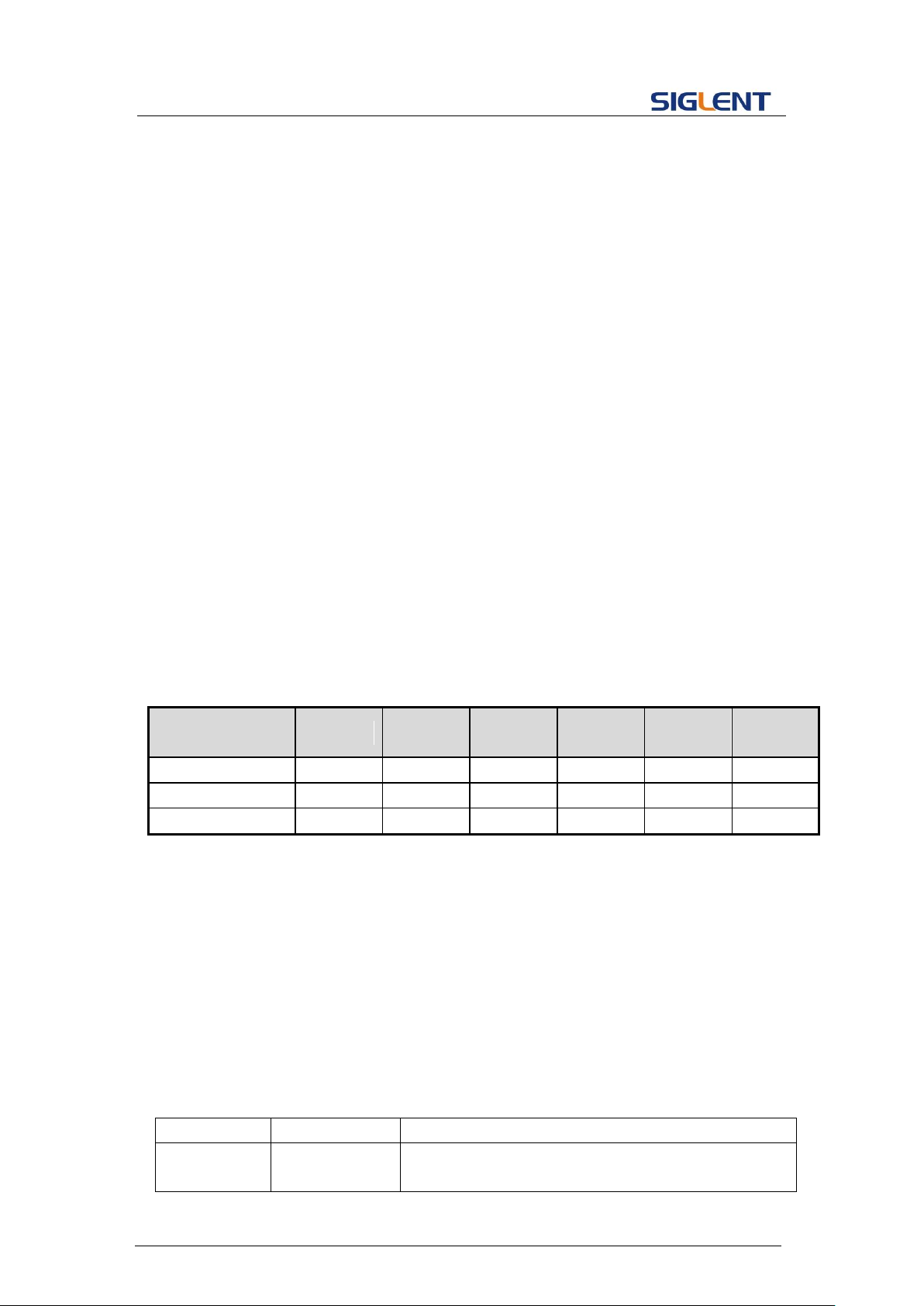
Parameter
/command
SDG800
SDG1000
SDG2000X
SDG5000
SDG1000X
SDG6000X
/X-E
<channel>
no
yes
yes
yes
yes
yes
TRMD
no
yes
yes
yes
yes
yes
EDGE
no
yes
yes
yes
yes
yes
DESCRIPTION
This commend sets or gets the burst wave parameters.
COMMAND SYNTAX
<channel>:BursTWaVe <parameter>,<value>
<channel>:= {C1, C2}.
<parameter>:= {a parameter from the table below}.
<value>:= {value of the corresponding parameter}.
Parameters
Value
Description
STATE
<state>
:= {ON, OFF}. Enable or disable burst.
STATE must be set to ON before you set or read other
Note: The table below shows the availability of some command parameters in each SDG
series.
3.7 Burst Wave Command
27
Page 29
Programming Guide
parameters of the burst.
PRD
<period>
:= burst period. Refer to the data sheet for the range
of valid values. The unit is seconds “s”. Not valid
when:
Carrier is NOISE
GATE_NCYC is GATE (except "X" series)
TRSR is EXT
STPS
<start_phase>
:= {0 to 360}. Start phase of the carrier. The unit is
"degree". Not valid when the carrier is NOISE or
PULSE.
GATE_NCYC
<burst_mode>
:= {GATE, NCYC}. Burst mode. Not valid when the
carrier is NOISE.
TRSR
<trig_src>
:= {EXT, INT, MAN}. Trigger source. EXT refers to
External, INT refers to Internal and MAN refers to
Manual.
MTRIG
:= send a manual trigger. Only when TRSR is MAN,
the parameter is valid.
DLAY
<delay>
:= trigger delay. The unit is seconds "s". Refer to the
data sheet for the range of valid values. Available
when GATE_NCYC is NCYC. Not valid when the
carrier is NOISE.
PLRT
<polarity>
:= {NEG, POS}. Gate polarity. Negative or Positive.
TRMD
<trig_mode>
:= {RISE, FALL, OFF}. Trigger out mode. Available
when GATE_NCYC is NCYC and TRSR is INT or
MAN. Not valid when the carrier is NOISE.
EDGE
<edge>
:={RISE, FALL}. Available trigger edge. Only valid
when TRSR is EXT or MAN.
EDGE
<edge>
:= { RISE, FALL}. Available trigger edge. Available
when GATE_NCYC is NCYC and TRSR is EXT. Not
valid when the carrier is NOISE.
TIME
<circle_ time>
:={INF, 1, 2,..., M}, where M is the maximum
supported Ncycle number which depends on the
model; INF sets the burst to Infinite mode.
Available when GATE_NCYC is NCYC. Not valid
when the carrier is NOISE.
CARR,
WVTP
<wave type>
:= {SINE, SQUARE, RAMP, ARB, PULSE, NOISE}.
Carrier waveform type.
CARR, FRQ
<frequency>
:= carrier frequency. The unit is Hertz "Hz". Refer to
the data sheet for the range of valid values.
CARR,
PHSE
<phase>
:= {0 to 360}. Carrier phase. The unit is "degree".
CARR, AMP
<amplitude>
:= carrier amplitude. The unit is volts, peak-to-peak
"Vpp". Refer to the data sheet for the range of valid
28
Page 30
Programming Guide
values.
CARR, OFST
<offset>
:= carrier offset. The unit is volts "V". Refer to the data
sheet for the range of valid values.
CARR, SYM
<symmetry>
:= {0 to 100}. Carrier symmetry when the carrier is
RAMP. The unit is "%".
CARR,
DUTY
<duty>
:= {0 to 100}. Carrier duty cycle when the carrier is
SQUARE or PULSE. The unit is "%".
CARR, RISE
<rise>
:= rise time when the carrier is PULSE. The unit is
seconds "s". Refer to the data sheet for the range of
valid values.
CARR, FALL
<fall>
:= fall time when the carrier is PULSE. The unit is
seconds "s". Refer to the data sheet for the range of
valid values.
CARR, DLY
<delay>
:= pulse delay when the carrier is PULSE. The unit is
seconds “s”. Refer to the data sheet for the range of
valid values.
CARR,
STDEV
<stdev>
:= standard deviation of NOISE. The unit is volts “V”.
Refer to the data sheet for the range of valid values.
CARR,
MEAN
<mean>
:= mean of NOISE. The unit is volts “V”. Refer to the
data sheet for the range of valid values.
QUERY SYNTAX
<channel>:BTWV(BursTWaVe)?
<channel>:={C1, C2}
RESPONSE FORMAT
<channel>:BTWV <parameter>
<parameter>:={All parameters of the current burst wave.}
EXAMPLE
Set CH1 burst state to ON
C1:BTWV STATE,ON
Set CH1 burst period to 1 s.
C1:BTWV PRD,1
Set CH1 burst delay to 1 s
C1:BTWV DLAY,1
Set CH1 burst to infinite
C1:BTWV TIME,INF
Read CH2 burst parameters when the STATE is ON.
C2:BTWV?
Return:
C2:BTWV STATE,ON,PRD,0.01S,STPS,0,TRSR,INT,
29
Page 31
Programming Guide
TRMD,OFF,TIME,1,DLAY,2.4e-07S,GATE_NCYC,NCYC,
CARR,WVTP,SINE,FRQ,1000HZ,AMP,4V,OFST,0V,PHSE,0
Read CH2 burst parameters when the STATE is OFF.
C2:BTWV?
Return:
C2:BTWV STATE,OFF
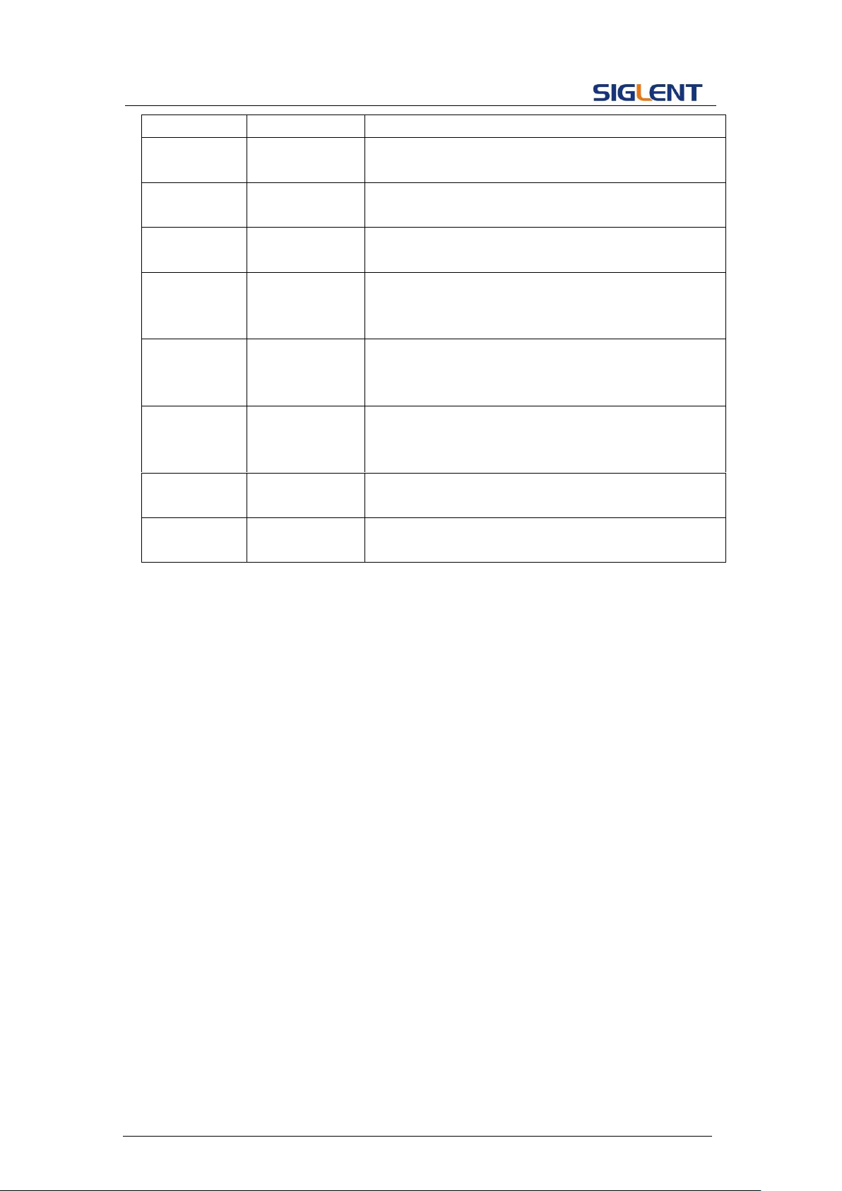
Parameter
/command
SDG800
SDG1000
SDG2000X
SDG5000
SDG1000X
SDG6000X
/X-E
<channel>
no
yes
yes
yes
yes
yes
TRMD
no
yes
yes
yes
yes
yes
EDGE
no
yes
yes
yes
yes
yes
CARR, DLY
yes
yes
yes
yes
yes
yes
CARR, RISE
yes
no
yes
yes
yes
yes
CARR, FALL
yes
no
yes
yes
yes
yes
DESCRIPTION
This command copies parameters from one channel to another.
COMMAND SYNTAX
ParaCoPy <destination_channel>,<src_channel>
< destination_channel>:= {C1, C2}.
<src_channel>:= {C1, C2}.
Note: the parameters C1 and C2 must be set to the device
together.
EXAMPLE
Copy parameters from CH1 to CH2.
PACP C2,C1
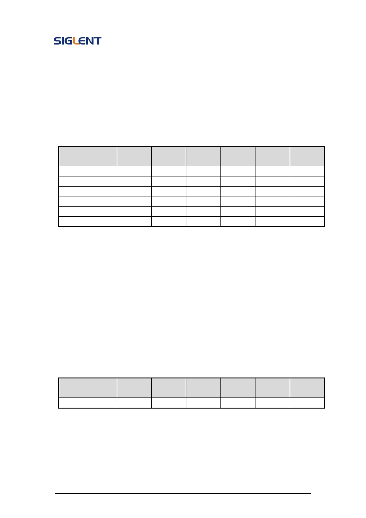
Parameter
/command
SDG800
SDG1000
SDG2000X
SDG5000
SDG1000X
SDG6000X
/X-E
PACP
no
yes
yes
yes
yes
yes
DESCRIPTION
This command sets and gets the arbitrary waveform type.
Note: The index number in the command syntax and the response
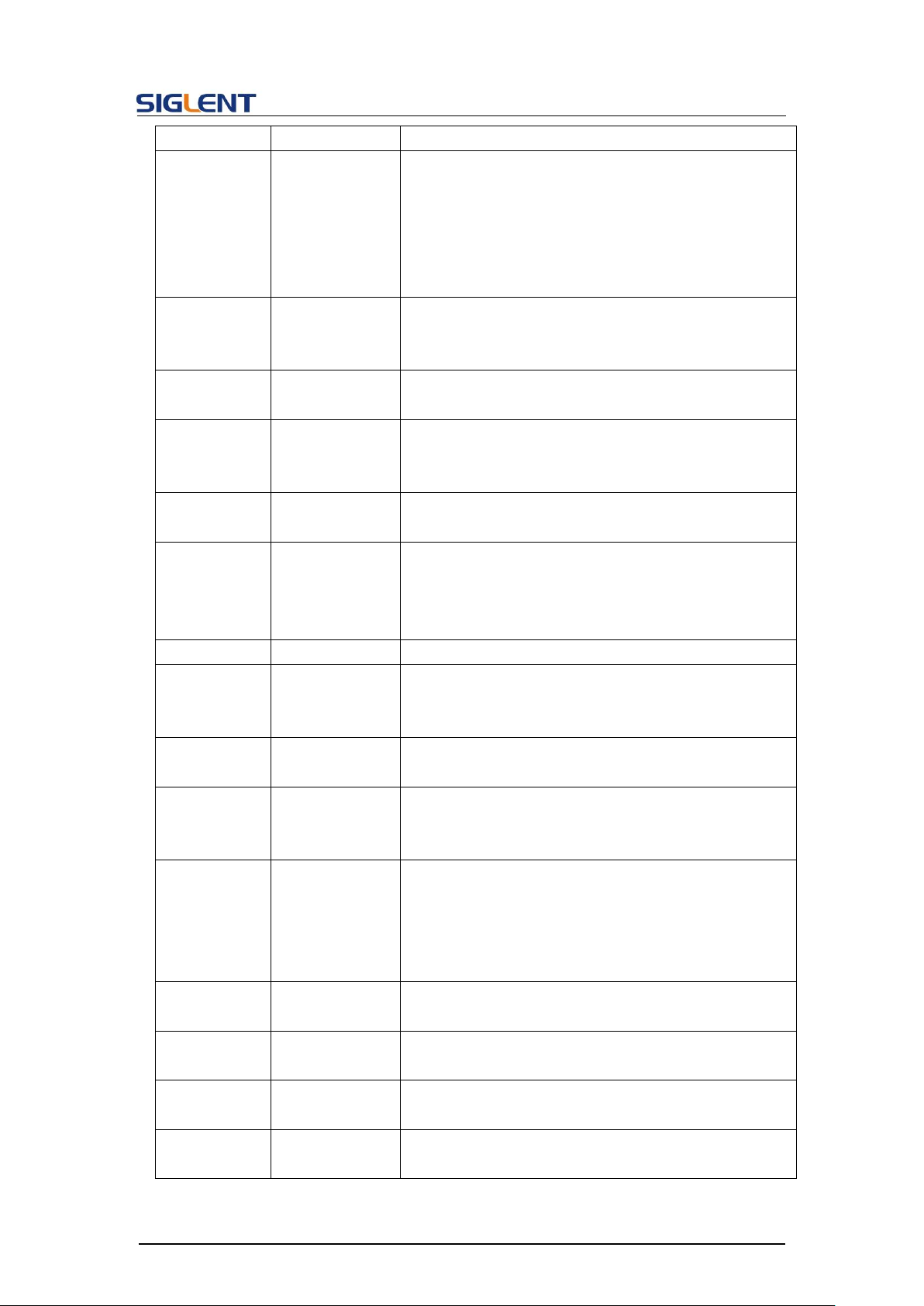
Note: The table below shows the availability of some command parameters in each SDG
series.
3.8 Parameter Copy Command
Note: The table below shows the availability of the command in each SDG series.
3.9 Arbitrary Wave Command
30
Page 32
Programming Guide
format of query omit the character ‘M’, and directly uses the value
to represent the index number.
COMMAND SYNTAX
<channel>:ArbWaVe INDEX,<index>
<channel>:ArbWaVe NAME,<name>
<channel>:= {C1, C2}.
<index>: the index of the arbitrary waveform from the table below.
<name>: the name of the arbitrary waveform from the table below.
.QUERY SYNTAX
<channel>:ARbWaVe?
<channel>:= {C1, C2}.
RESPONSE FORMAT
<channel>:ARWV INDEX,<index>,NAME,<name>
EXAMPLE
Set CH1 current waveform by index 2:
C1:ARWV INDEX,2
Read CH1 current waveform:
C1:ARWV?
Return:
C1:ARWV INDEX,2,NAME,StairUp
Set CH1 current waveform to wave_1 by name.
C1:ARWV NAME,wave_1
RELATED COMMANDS
STL
Index
Name
Index
Name
Index
Name
Index
Name
0
Sine
12
Logfall
24
Gmonopuls
36
Triang
1
Noise
13
Logrise
25
Tripuls
37
Harris
2
StairUp
14
Sqrt
26
Cardiac
38
Bartlett
3
StairDn
15
Root3
27
Quake
39
Tan
4
Stairud
16
X^2
28
Chirp
40
Cot
5
Ppulse
17
X^3
29
Twotone
41
Sec
6
Npulse
18
Sinc
30
Snr
42
Csc
7
Trapezia
19
Gaussian
31
Hamming
43
Asin
8
Upramp
20
Dlorentz
32
Hanning
44
Acos
9
Dnramp
21
Haversine
33
Kaiser
45
Atan
10
Exp_fall
22
Lorentz
34
Blackman
46
Acot
11
Exp_rise
23
Gauspuls
35
Gausswin
47
Square
Note: This table is just an example, the index depends on the specific model. The “STL?”
command can be used to get the accurate mapping relationship between the index and
name.
31
Page 33
Programming Guide
Parameter
/command
SDG800
SDG1000
SDG2000X
SDG5000
SDG1000X
SDG6000X
/X-E
<channel>
no
yes
yes
yes
yes
yes
INDEX
yes
yes
yes(only
built-in
wave)
yes
yes(only
built-in
wave)
yes(only
built-in
wave)
NAME
yes
yes
yes(only
user
defined
wave)
yes
yes(only
user
defined
wave)
yes(only
user
defined
wave)
DESCRIPTION
This command sets the synchronization signal.
COMMAND SYNTAX
<channel>:SYNC <state>
<channel>:= {C1, C2}.
<state>:= {ON, OFF}.
SYNC TYPE, <TYPE>
<TYPE>:={CH1,CH2,MOD_CH1,MOD_CH2}.
QUERY SYNTAX
<channel>:SYNC?
<channel>:= {C1, C2}.
RESPONSE FORMAT
<channel>:SYNC <state>
EXAMPLE
Turn on sync output and set the source as modulating signal of
CH1:
C1:SYNC ON,TYPE,MOD_CH1
Read state of CH1 sync.
C1:SYNC?
Return:
C1:SYNC ON,TYPE,MOD_CH1
Parameter
/command
SDG800
SDG1000
SDG2000X
SDG5000
SDG1000X
SDG6000X
/X-E
SYNC
no
yes
yes
yes
yes
yes
Note: The table below shows the availability of some command parameters in each SDG
series.
3.10 Sync Command
Note: The table below shows the availability of the command in each SDG series.
32
Page 34

Programming Guide
DESCRIPTION
This command sets or gets the number format.
COMMAND SYNTAX
NumBer_ForMat PNT,<pnt>,
NumBer_ForMa SEPT,<sept>
<pnt>:= {Dot, Comma}. The point format.
<sept>:= {Space, Off, On}. The separator format.
QUERY SYNTAX
NBFM?
RESPONSE FORMAT
NBFM PNT,<pnt>, SEPT,<sept>
EXAMPLE
Set point format to DOT:
NBFM PNT,DOT
Set separator format to ON:
NBFM SEPT,ON
Read the number format:
NBFM?
Return:
NBFM PNT, DOT, SEPT, ON
DESCRIPTION
This command sets or gets the system language.
COMMAND SYNTAX
LAnGuaGe <language>
<language>:= {EN,CH,RU}, where EN is English, CH is Chinese
Simplified, and RU is Russian.
QUERY SYNTAX
LAnGuaGe?
RESPONSE FORMAT
LAGG <language>
EXAMPLE
Set language to English:
LAGG EN
Read language
LAGG?
3.11 Number Format Command
3.12 Language Command
33
Page 35
Programming Guide
Return:
LAGG EN
Parameter
/command
SDG800
SDG1000
SDG2000X
SDG5000
SDG1000X
SDG6000X
/X-E
RU
no
yes
no
no
no
no
DESCRIPTION
This command sets or gets the the power-on system setting.
COMMAND SYNTAX
Sys_CFG <mode>
<mode>:= {DEFAULT, LAST}
QUERY SYNTAX
Sys_CFG?
RESPONSE FORMAT
SCFG <mode>
EXAMPLE
Set the power-on system setting to LAST:
SCFG LAST
DESCRIPTION
This command turns on or off the buzzer.
COMMAND SYNTAX
BUZZer <state>
<state>:= {ON, OFF}.
QUERY SYNTAX
BUZZer?
RESPONSE FORMAT
BUZZ <state>
EXAMPLE
Turn on the buzzer:
BUZZ ON
Note: The table below shows the availability of some command parameters in each SDG
series.
3.13 Configuration Command
3.14 Buzzer Command
34
Page 36
Programming Guide
DESCRIPTION
This commands turns off or sets screen save time (the unit is
minutes).
COMMAND SYNTAX
SCreen_SaVe <parameter>
<parameter>:= {OFF, 1, 5, 15, 30, 60, 120, 300}.
QUERY SYNTAX
SCreen_SaVe?
RESPONSE FORMAT
SCSV <parameter>
EXAMPLE
Set screen save time to 5 minutes:
SCSV 5
Read the current screen save time:
SCreen_SaVe?
Return:
SCSV 5MIN
DESCRIPTION
This command sets or gets the clock source.
COMMAND SYNTAX
ROSCillator <src>
<src>:= {INT, EXT}
ROSC 10MOUT,ON|OFF
QUERY SYNTAX
ROSC?
RESPONSE FORMAT
ROSC <src>,10MOUT,ON|OFF
EXAMPLE
Set internal time base as the source:
ROSC INT
Enable 10MHz output:
ROSC 10MOUT,ON
Parameter
SDG800
SDG1000
SDG2000X
SDG5000
SDG1000X
SDG6000X
3.15 Screen Save Command
3.16 Clock Source Command
Note: The table below shows the availability of the command in each SDG series.
35
Page 37
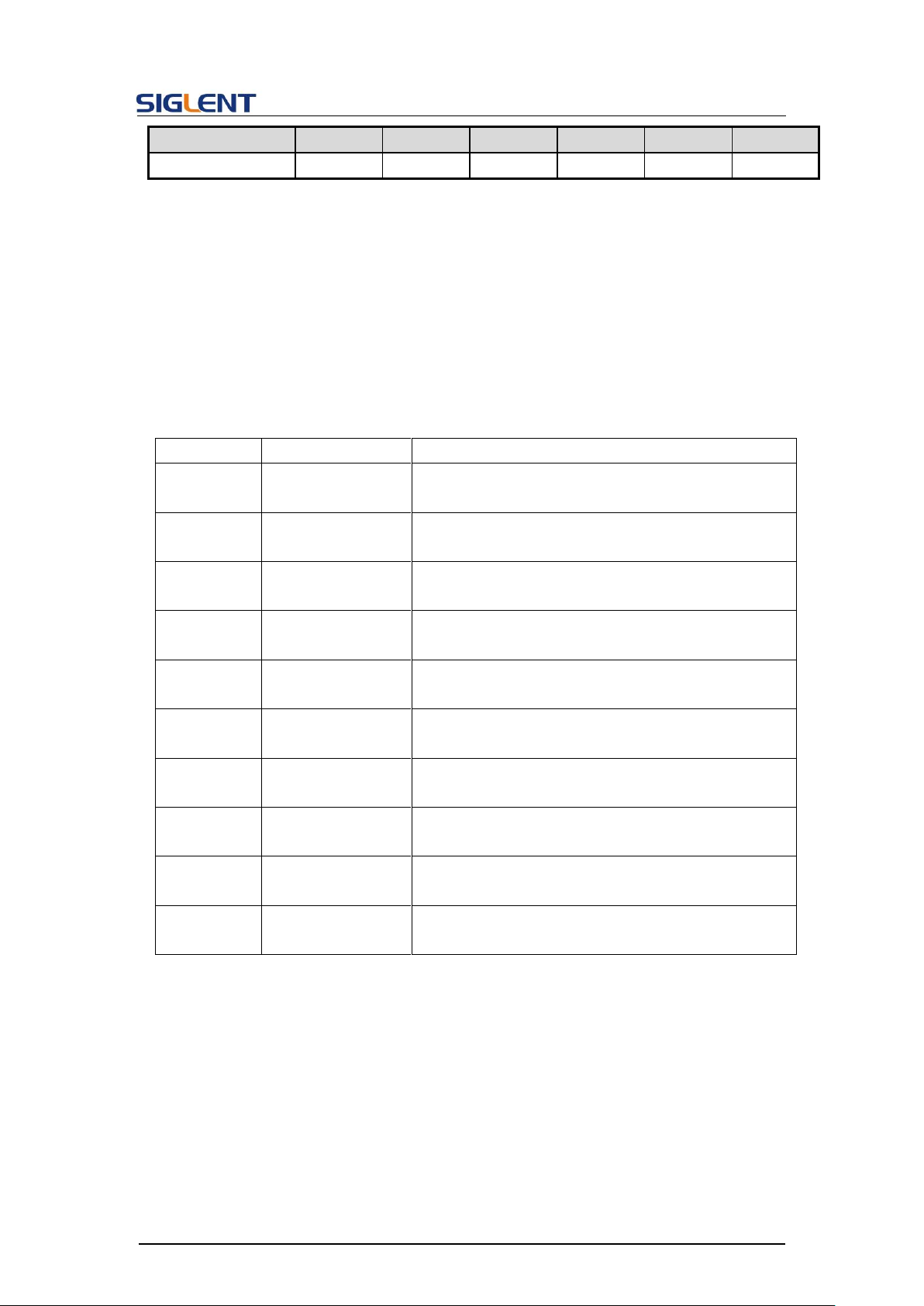
/command
/X-E
ROSC
no
yes
yes
yes
yes
yes
DESCRIPTION
This command sets or gets the frequency counter parameters.
COMMAND SYNTAX
FreqCouNTer <parameter>,<value>
<parameter>:= {a parameter from the table below}.
<value>:= {value of the corresponding parameter}.
Parameters
Value
Description
STATE
<state>
:={ON, OFF}
State of frequency counter.
FRQ
<frequency>
Measured frequency. The unit is Hertz “Hz”.
Can’t be set.
PW
<pos_width>
Measured positive width. The unit is seconds “s”.
Can’t be set.
NW
<neg_width>
Measured negative width. The unit is seconds “s”.
Can’t be set.
DUTY
<duty>
Measured duty cycle. The unit is "%".
Can’t be set.
FRQDEV
<freq_dev>
Measured frequency deviation. The unit is "ppm".
Can’t be set.
REFQ
<ref_freq>
Expected frequency, for calculating the frequency
deviation. The unit is Hertz “Hz”.
TRG
<triglev>
Trigger level. The range of valid values depends on
the model. The unit is volts “V”.
MODE
<mode>
:={AC, DC}
Coupling mode.
HFR
<HFR>
:={ON, OFF}
State of High Frequency Rejection.
QUERY SYNTAX
FreqCouNTer?
RESPONSE FORMAT
FCNT <parameter>
<parameter>:={All parameters of the frequency counter}
EXAMPLE
Turn frequency counter on:
FCNT STATE,ON
Set reference freq to 1000 Hz:
3.17 Frequency Counter Command
Programming Guide
36
Page 38
Programming Guide
FCNT REFQ,1000
Query frequency counter information:
FCNT?
Return:
FCNT STATE,ON,FRQ,10000000HZ,DUTY,59.8568,REFQ,
1e+07HZ,TRG,0V,PW,5.98568e-08S,NW,4.01432e08S,FRQDEV,0ppm,MODE,AC,HFR,OFF
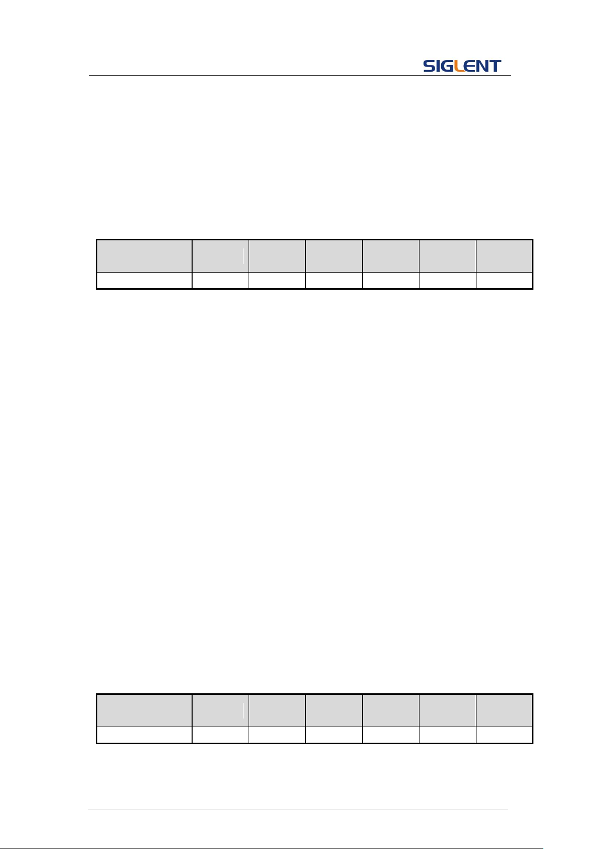
Parameter
/command
SDG800
SDG1000
SDG2000X
SDG5000
SDG1000X
SDG6000X
/X-E
FCNT
no
yes
yes
yes
yes
yes
DESCRIPTION
This command sets or gets the polarity of specified channel.
COMMAND SYNTAX
<channel>:INVerT <state>
<channel>:= {C1, C2}.
<state>:= {ON, OFF}.
QUERY SYNTAX
<channel>:INVerT?
<channel>:={C1, C2}.
RESPONSE FORMAT
<channel>:INVT <state>
EXAMPLE
Set CH1 polarity to invert
C1:INVT ON
Read the polarity of CH1.
C1:INVT?
Return:
C1:INVT ON
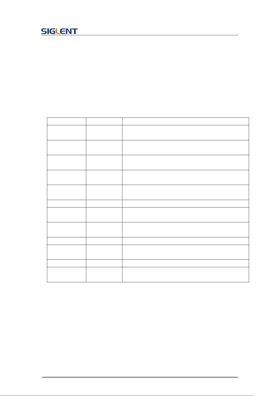
Parameter
/command
SDG800
SDG1000
SDG2000X
SDG5000
SDG1000X
SDG6000X
/X-E
<channel>
no
yes
yes
yes
yes
yes
Note: The table below shows the availability of the command in each SDG series.
3.18 Invert Command
Note: The table below shows the availability of some command parameters in each SDG
series.
37
Page 39
3.19 Coupling Command
DESCRIPTION
This command sets or gets the channel coupling parameters.
Only when TRACE is set to OFF, the other coupling parameters can
be set.
COMMAND SYNTAX
COUPling <parameter>,<value>
<parameter>:= {a parameter from the table below}.
<value>:={value of the corresponding parameter}.
Parameters
Value
Description
TRACE
<track_enble>
:= {ON, OFF}
State of channel tracking.
STATE
<state>
:= {ON, OFF}
State of channel coupling.
BSCH
<bsch>
:= {CH1,CH2}
Base channel.
FCOUP
<fcoup>
:= {ON, OFF}
State of frequency coupling
FDEV
<frq_dev>
:= frequency deviation between the 2 channels. The unit
is Hertz “Hz”.
FRAT
<frat>
:= frequency ratio between the 2 channels.
PCOUP
<pcoup>
:={ON, OFF}
State of phase coupling
PDEV
<pha_dev>
:= phase deviation between the 2 channels. The unit is
“degree”.
PRAT
<prat>
:= phase ratio between the 2 channels.
ACOUP
<acoup>
:= {ON, OFF}
State of amplitude coupling
ARAT
<arat>
:= amplitude ratio between the 2 channels.
ADEV
<adev>
:= amplitude deviation between the 2 channels. The unit
is volts, peak-to-peak “Vpp”.
QUERY SYNTAX
RESPONSE FORMAT
EXAMPLE
COUPling?
COUP <parameter>
<parameter>:= { All parameters of coupling}.
Set coupling state to ON:
COUP STATE,ON
Set frequency coupling state to ON:
Programming Guide
38
Page 40
Programming Guide
COUP FCOUP,ON
Set frequency deviation to 5 Hz:
COUP FDEV,5
Query coupling information.
COUP?
Return:
COUP TRACE,OFF,FCOUP,ON,PCOUP,ON,ACOUP,ON,FDEV,
5HZ,PRAT,1,ARAT,2
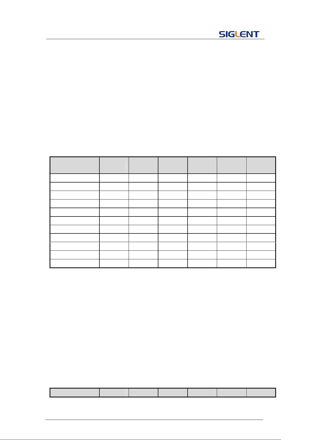
Parameter
/command
SDG800
SDG1000
SDG2000X
SDG5000
SDG1000X
SDG6000X
/X-E
COUP
no
yes
yes
yes
yes
yes
TRACE
no
no
yes
no
yes
yes
STATE
no
yes
no
yes
no
no
BSCH
no
yes
no
yes
no
no
FCOUP
no
no
yes
no
yes
yes
FRAT
no
no
Yes
no
yes
yes
PCOUP
no
no
Yes
no
yes
yes
PRAT
no
no
Yes
no
yes
yes
ACOUP
no
no
Yes
no
yes
yes
ARAT
no
no
Yes
no
yes
yes
ADEV
no
no
yes
no
yes
yes
DESCRIPTION
This commend sets or gets the state of over-voltage protection.
COMMAND SYNTAX
VOLTPRT <state>
<state>:= {ON, OFF}
QUERY SYNTAX
VOLTPRT?
RESPONSE FORMAT
VOLTPRT <state>
Parameter
SDG800
SDG1000
SDG2000X
SDG5000
SDG1000X
SDG6000X
Note: The table below shows the availability of the command and some parameters in each
SDG series.
3.20 Over-Voltage Protection Command
Note: The table below shows the availability of the command in each SDG series.
39
Page 41
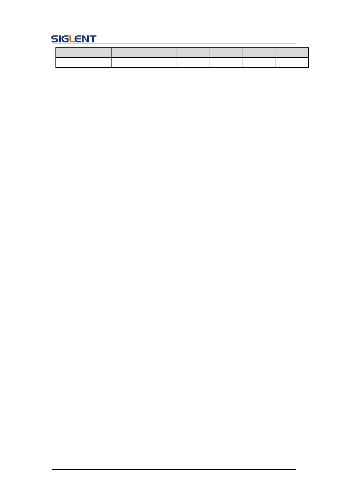
/command
/X-E
VOLTPRT
no
yes
yes
no
yes
yes
DESCRIPTION
This command is used to read the stored waveforms list with
indexes and names. If the store unit is empty, the command will
return “EMPTY” string.
QUERY SYNTAX
SToreList?
SToreList? BUILDIN|USER
EXAMPLE
Read all arbitrary data saved in a SDG1000.
STL?
Return:
STL M0, sine, M1, noise, M2, stairup, M3, stairdn, M4, stairud,
M5, ppulse, M6, npulse, M7, trapezia, M8, upramp, M9, dnramp,
M10, exp_fall, M11, exp_rise, M12, logfall, M13, logrise, M14,
sqrt, M15, root3, M16, x^2, M17, x^3, M18, sinc, M19, gaussian,
M20, dlorentz, M21, haversine, M22, lorentz, M23, gauspuls,
M24, gmonopuls, M25, tripuls, M26, cardiac, M27, quake, M28,
chirp, M29, twotone, M30, snr, M31, EMPTY, M32, EMPTY, M33,
EMPTY, M34, hamming, M35, hanning, M36, kaiser, M37,
blackman, M38, gaussiwin, M39, triangle, M40, blackmanharris,
M41, bartlett, M42, tan, M43, cot, M44, sec, M45, csc, M46, asin,
M47, acos, M48, atan, M49, acot, M50, EMPTY, M51, EMPTY,
M52, EMPTY, M53, DDROPOUT, M54, FCLK1, M55, FSDA1,
M56, EMPTY, M57, EMPTY, M58, EMPTY, M59, EMPTY
3.21 Store List Command
Programming Guide
Read built-in wave data from a SDG2000X:
STL? BUILDIN
Return:
STL M10, ExpFal, M100, ECG14, M101, ECG15, M102,
LFPulse, M103, Tens1, M104, Tens2, M105, Tens3, M106,
Airy, M107, Besselj, M108, Bessely, M109, Dirichlet, M11,
ExpRise, M110, Erf, M111, Erfc, M112, ErfcInv, M113, ErfInv,
M114, Laguerre, M115, Legend, M116, Versiera, M117,
Weibull, M118, LogNormal, M119, Laplace, M12, LogFall,
M120, Maxwell, M121, Rayleigh, M122, Cauchy, M123, CosH,
M124, CosInt, M125, CotH, M126, CscH, M127, SecH, M128,
SinH, M129, SinInt, M13, LogRise, M130, TanH, M131,
ACosH, M132, ASecH, M133, ASinH, M134, ATanH, M135,
40
Page 42

Programming Guide
ACsch, M136, ACoth, M137, Bartlett, M138, BohmanWin,
M139, ChebWin, M14, Sqrt, M140, FlattopWin, M141,
ParzenWin, M142, TaylorWin, M143, TukeyWin, M144,
SquareDuty01, M145, SquareDuty02, M146, SquareDuty04,
M147, SquareDuty06, M148, SquareDuty08, M149,
SquareDuty10, M15, Root3, M150, SquareDuty12, M151,
SquareDuty14, M152, SquareDuty16, M153, SquareDuty18,
M154, SquareDuty20, M155, SquareDuty22, M156,
SquareDuty24, M157, SquareDuty26, M158, SquareDuty28,
M159, SquareDuty30, M16, X^2, M160, SquareDuty32, M161,
SquareDuty34, M162, SquareDuty36, M163, SquareDuty38,
M164, SquareDuty40, M165, SquareDuty42, M166,
SquareDuty44, M167, SquareDuty46, M168, SquareDuty48,
M169, SquareDuty50, M17, X^3, M170, SquareDuty52, M171,
SquareDuty54, M172, SquareDuty56, M173, SquareDuty58,
M174, SquareDuty60, M175, SquareDuty62, M176,
SquareDuty64, M177, SquareDuty66, M178, SquareDuty68,
M179, SquareDuty70, M18, Sinc, M180, SquareDuty72,
M181, SquareDuty74, M182, SquareDuty76, M183,
SquareDuty78, M184, SquareDuty80, M185, SquareDuty82,
M186, SquareDuty84, M187, SquareDuty86, M188,
SquareDuty88, M189, SquareDuty90, M19, Gaussian, M190,
SquareDuty92, M191, SquareDuty94, M192, SquareDuty96,
M193, SquareDuty98, M194, SquareDuty99, M195,
demo1_375pts, M196, demo1_16kpts, M197, demo2_3kpts,
M198, demo2_16kpts, M2, StairUp, M20, Dlorentz, M21,
Haversine, M22, Lorentz, M23, Gauspuls, M24, Gmonopuls,
M25, Tripuls, M26, Cardiac, M27, Quake, M28, Chirp, M29,
Twotone, M3, StairDn, M30, SNR, M31, Hamming, M32,
Hanning, M33, kaiser, M34, Blackman, M35, Gausswin, M36,
Triangle, M37, Bartlett-Hann, M38, Bartlett, M39, Tan, M4,
StairUD, M40, Cot, M41, Sec, M42, Csc, M43, Asin, M44,
Acos, M45, Atan, M46, Acot, M47, Square, M48, SineTra, M49,
SineVer, M5, Ppulse, M50, AmpALT, M51, AttALT, M52,
RoundHalf, M53, RoundsPM, M54, BlaseiWave, M55,
DampedOsc, M56, SwingOsc, M57, Discharge, M58, Pahcur,
M59, Combin, M6, Npulse, M60, SCR, M61, Butterworth, M62,
Chebyshev1, M63, Chebyshev2, M64, TV, M65, Voice, M66,
Surge, M67, Radar, M68, Ripple, M69, Gamma, M7, Trapezia,
M70, StepResp, M71, BandLimited, M72, CPulse, M73,
CWPulse, M74, GateVibr, M75, LFMPulse, M76, MCNoise,
M77, AM, M78, FM, M79, PFM, M8, Upramp, M80, PM, M81,
PWM, M82, EOG, M83, EEG, M84, EMG, M85, Pulseilogram,
M86, ResSpeed, M87, ECG1, M88, ECG2, M89, ECG3, M9,
41
Page 43
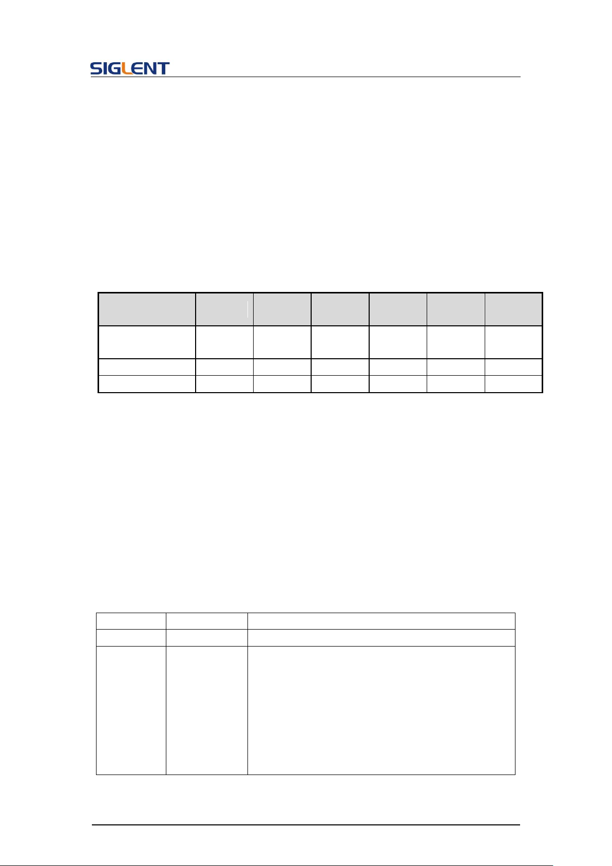
Programming Guide
Parameter
/command
SDG800
SDG1000
SDG2000X
SDG5000
SDG1000X
SDG6000X
/X-E
STL? return
BUILDIN
USER
BUILDIN
USER
BUILDIN
BUILDIN
USER
BUILDIN
BUILDIN
BUILDIN
no
no
yes
no
yes
yes
USER
no
no
yes
no
yes
yes
DESCRIPTION
This command sets and gets the arbitrary waveform data.
COMMAND SYNTAX
<channel>:WVDT <index>,<parameter>,<value>
<channel>:= {C1, C2}.
<index>:= {Mn}. The waveform index. See note 2 below for the
details.
<parameter>:= {a parameter from the table below}.
<value>:= {value of the corresponding parameter}.
Parameters
Value
Description
WVNM
<wave_name>
:= waveform name.
TYPE
<type>
:= {0 to 5}
0 - common
1 - math
2 - engineering
3 - window
4 - triangle function
5 - user defined
This parameter is not valid for the “X” series.
Dnramp, M90, ECG4, M91, ECG5, M92, ECG6, M93, ECG7,
M94, ECG8, M95, ECG9, M96, ECG10, M97, ECG11, M98,
ECG12, M99, ECG13
Read wave data defined by user from a SDG1000X:
STL? USER
Return:
STL WVNM,sinc_8M,sinc_3000000,sinc_1664000,
ramp_8M,sinc_2000000,sinc_50000,square_8M,sinc_5000,
wave1,square_1M
Note: The table below shows the availability of some command parameters in each SDG
series.
3.22 Arb Data Command
42
Page 44
Programming Guide
LENGTH
<length>
:= the number of waveform bytes, the valid range
depends on the model. See note 1 below for the
details.
This parameter is not necessary in the “X” series
FREQ
<frequency>
:= frequency. The unit is Hertz “Hz”.
AMPL
<amplifier>
:= amplitude. The unit is volts, peak-to-peak “Vpp”.
OFST
<offset>
:= offset. The unit is volts “V”.
PHASE
<phase>
:= phase. The unit is "degree".
WAVEDATA
<wave data>
:= waveform data.
The wave data needs to be read from a waveform file
QUERY SYNTAX
Format 1: WVDT? Mn
Format 2: WVDT? USER,<wave_name>
<wave name>:={The name of user defined waveform}.
EXAMPLE
See section 4.1.5 for the example.
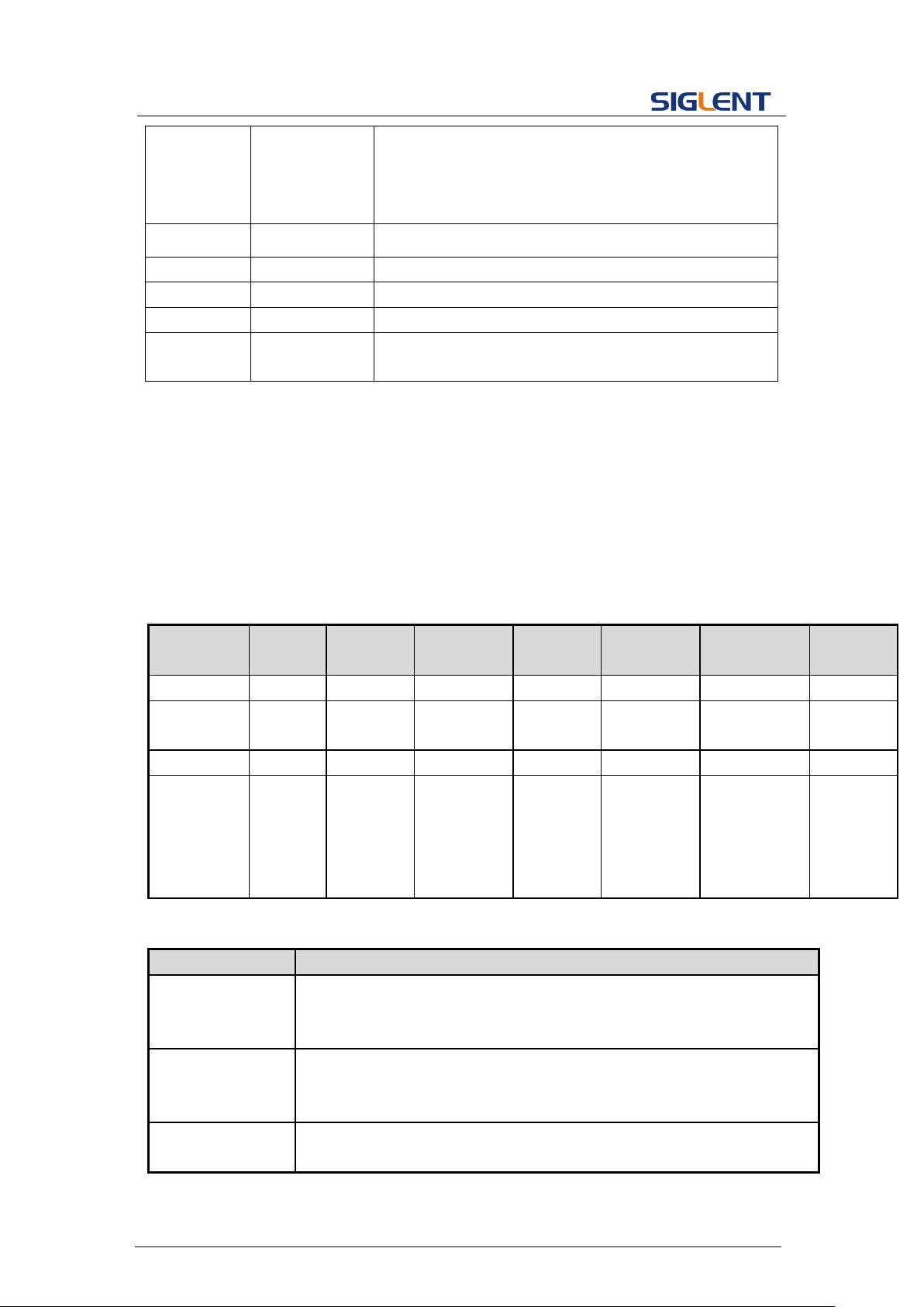
Parameter
/command
SDG800
SDG1000
SDG2000X
SDG5000
SDG1000X
SDG6000X-E
SDG6000X
TYPE
yes
yes
no
yes
no
no
no
<length>
32KB
32KB
4B~16MB
32KB,
1024KB
4B~16MB
4B~16MB
4B~40MB
USER
no
no
yes
no
yes
yes
yes
Format of
WVDT?
Format 1
Format 1
Built-in:
Format1
Userdefined:
Format2
Format 1
Built-in:
Format1
Userdefined:
Format2
Built-in:
Format1
User-defined:
Format2
Built-in:
Format1
Userdefined:
Format2
Model
Description of Mn
SDG800
0<=n<=59.
M0~M49: build-in (32KB).
M50~M59: user-defined (32KB).
SDG1000
0<=n<=59.
M0~M49: build-in (32KB).
M50~M59: user-defined (32KB).
SDG2000X
0<=n<=196.
M0~M196: build-in (32KB).
Notes:
1. The table below shows the availability of some command parameters in each SDG
series.
2. The table below shows the details of Mn parameters in each SDG series.
43
Page 45
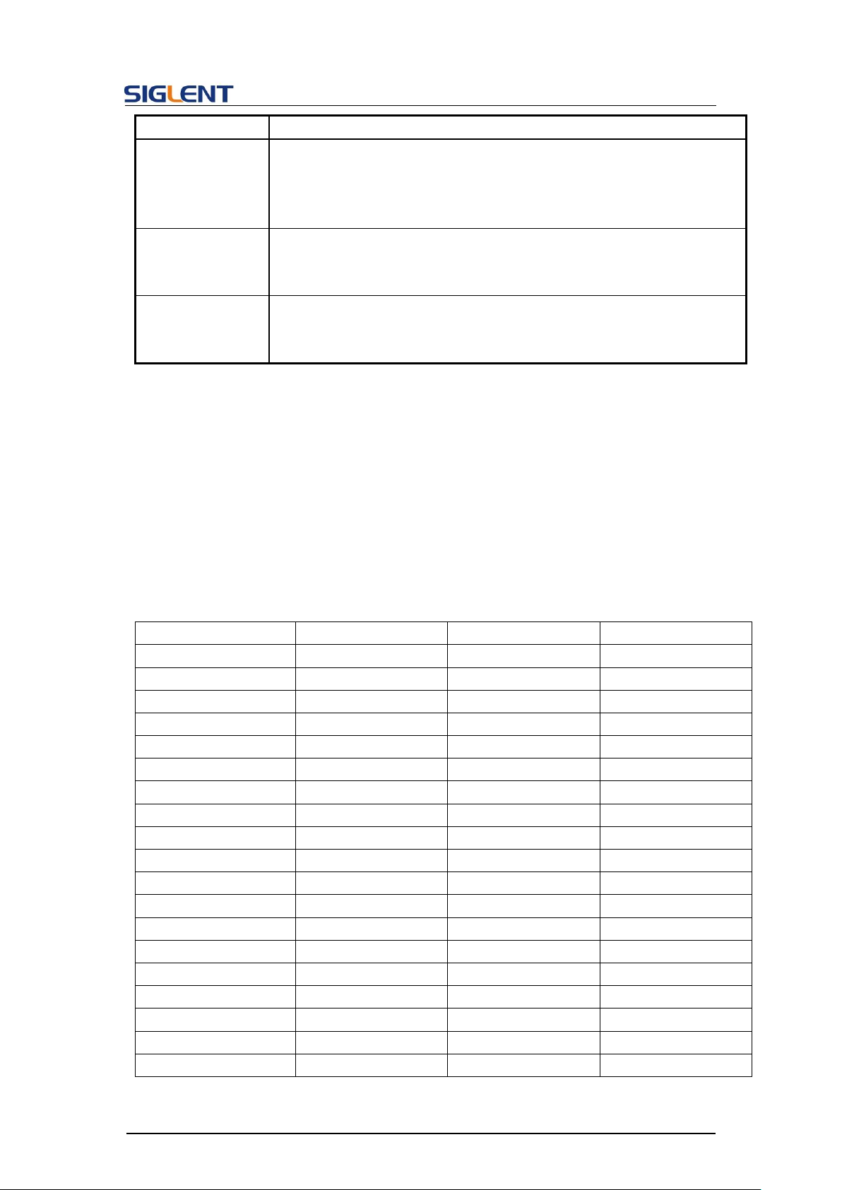
Not necessary when sending waveform data.
SDG5000
0<=n<=68.
M0~M35: build-in (32KB).
M36~M59: user-defined (32KB).
M60~M67: user-defined (1024KB).
SDG1000X
0<=n<=196.
M0~M196: build-in (32KB).
Not necessary when sending waveform data.
SDG6000X/X-E
0<=n<=196.
M0~M196: build-in (32KB).
Not necessary when sending waveform data.
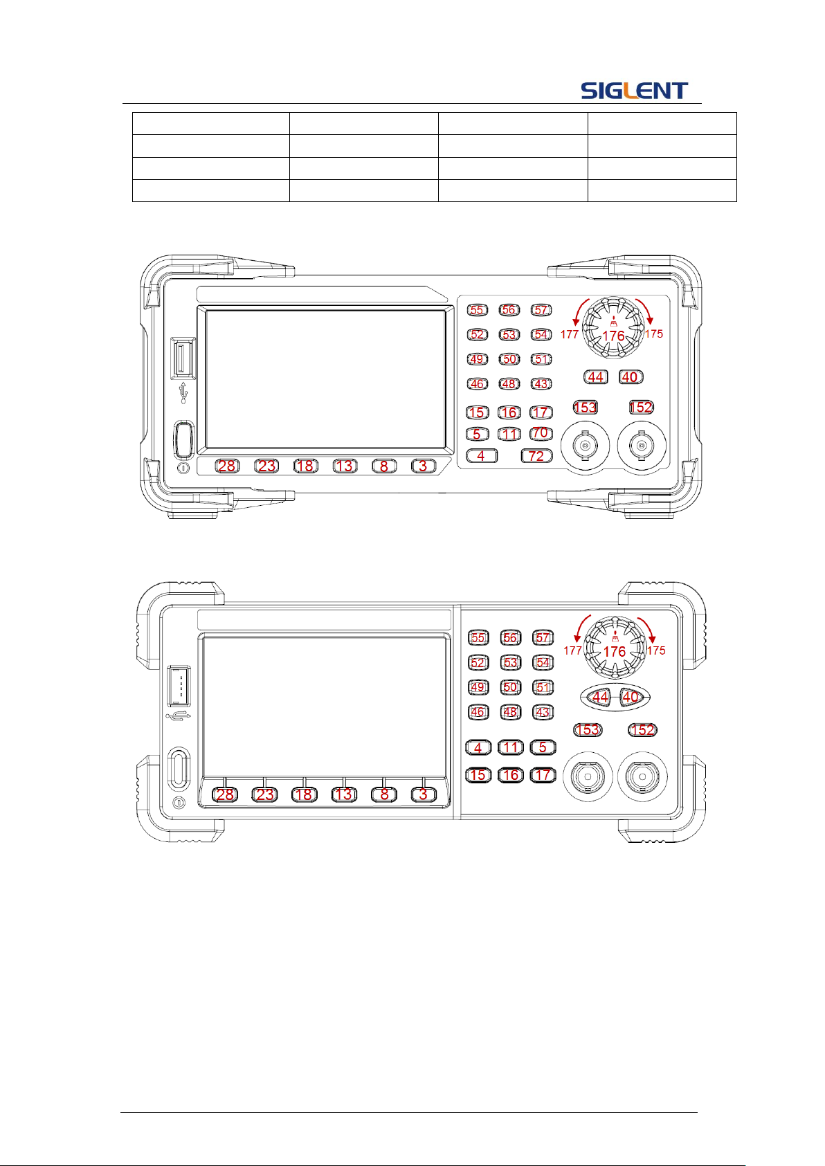
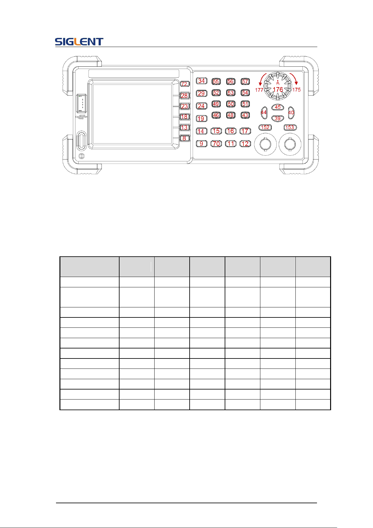
DESCRIPTION
This command is used to simulate pressing a key on the front panel.
COMMAND SYNTAX
VirtualKEY VALUE,<value>,STATE,<state>
<value>:= {a Name or Index of the virtual keys from the table below}.
<state>:= {0,1}, where “1” is effective to virtual value, and “0” is
useless.
Name
Index
Name
Index
KB_FUNC1
28
KB_NUMBER_4
52
KB_FUNC2
23
KB_NUMBER_5
53
KB_FUNC3
18
KB_NUMBER_6
54
KB_FUNC4
13
KB_NUMBER_7
55
KB_FUNC5
8
KB_NUMBER_8
56
KB_FUNC6
3
KB_NUMBER_9
57
KB_SINE
34
KB_POINT
46
KB_SQUARE
29
KB_NEGATIVE
43
KB_ RAMP
24
KB_LEFT
44
KB_PULSE
19
KB_RIGHT
40
KB_NOISE
14
KB_UP
45
KB_ARB
9
KB_DOWN
39
KB_MOD
15
KB_OUTPUT1
153
KB_SWEEP
16
KB_OUTPUT2
152
KB_BURST
17
KB_KNOB_RIGHT
175
KB_WAVES
4
KB_KNOB_LEFT
177
KB_UTILITY
11
KB_KNOB_DOWN
176
KB_PARAMETER
5
KB_HELP
12
KB_STORE_RECALL
70
KB_CHANNEL
72
3.23 Virtual Key Command
Programming Guide
44
Page 46
Programming Guide
KB_NUMBER_0
48
KB_NUMBER_1
49
KB_NUMBER_2
50
KB_NUMBER_3
51
Keys and Indices on the SDG1000X/SDG2000X/SDG6000X/SDG6000X-E
Keys and Indices on the SDG5000
45
Page 47
Programming Guide
Keys and Indices on the SDG1000/SDG800
EXAMPLE
VKEY VALUE,15,STATE,1
VKEY VALUE,KB_SWEEP,STATE,1
Parameter
/command
SDG800
SDG1000
SDG2000X
SDG5000
SDG1000X
SDG6000X
/X-E
KB_FUNC6
no
no
yes
yes
yes
yes
KB_STORE_RECAL
L
yes
yes
yes
no
yes
yes
KB_HELP
yes
yes
no
no
no
no
KB_CHANNEL
no
yes
yes
no
yes
yes
KB_SINE
yes
yes
no
no
no
no
KB_SQUARE
yes
yes
no
no
no
no
KB_ RAMP
yes
yes
no
no
no
no
KB_PULSE
yes
yes
no
no
no
no
KB_NOISE
yes
yes
no
no
no
no
KB_ARB
yes
yes
no
no
no
no
KB_UP
yes
yes
no
no
no
no
KB_DOWN
yes
yes
no
no
no
no
DESCRIPTION
This command sets and gets the system IP address.
Note: The table below shows the availability of some command parameters in each SDG
series.
3.24 IP Command
46
Page 48
Programming Guide
COMMAND SYNTAX
SYSTem:COMMunicate:LAN:IPADdress
“<parameter1>.<parameter2>.<parameter3>.<parameter4>”
<parameter1>:={an integer value between 1 and 223}.
<parameter2>:={an integer value between 0 and 255}.
<parameter3>:={an integer value between 0 and 255}.
<parameter4>:={an integer value between 0 and 255}.
QUERY SYNTAX
SYSTem:COMMunicate:LAN:IPADdress?
Parameter
/command
SDG800
SDG1000
SDG2000X
SDG5000
SDG1000X
SDG6000X
/X-E
SYST:COMM:LAN:I
PAD
no
no
yes
no
yes
yes
DESCRIPTION
This command sets and gets the system subnet mask.
COMMAND SYNTAX
SYSTem:COMMunicate:LAN:SMASk
“<parameter1>.<parameter2>.<parameter3>.<parameter4>”
<parameter1>:={an integer value between 0 and 255}.
<parameter2>:={an integer value between 0 and 255}.
<parameter3>:={an integer value between 0 and 255}.
<parameter4>:={an integer value between 0 and 255}.
QUERY SYNTAX
SYSTem:COMMunicate:LAN:SMASk?
EXAMPLES Set IP address to 10.11.13.203:
SYST:COMM:LAN:IPAD “10.11.13.203”
Get the IP address:
SYST:COMM:LAN:IPAD?
Return:
“10.11.13.203”
Note: The table below shows the availability of the command in each SDG series.:
3.25 Subnet Mask Command
EXAMPLES Set subnet mask to 255.0.0.0:
47
SYST:COMM:LAN:SMAS “255.0.0.0”
Get subnet mask:
Page 49
Programming Guide
Parameter
/command
SDG800
SDG1000
SDG2000X
SDG5000
SDG1000X
SDG6000X
/X-E
SYST:COMM:LAN:S
MAS
no
no
yes
no
yes
yes
DESCRIPTION
This command sets and gets the system gateway.
COMMAND SYNTAX
SYSTem:COMMunicate:LAN:GATeway
“<parameter1>.<parameter2>.<parameter3>.<parameter4>”
<parameter1>:={an integer value between 0 and 223}.
<parameter2>:={an integer value between 0 and 255}.
<parameter3>:={an integer value between 0 and 255}.
<parameter4>:={an integer value between 0 and 255}.
QUERY SYNTAX
SYSTem:COMMunicate:LAN:GATeway?
Parameter
/command
SDG800
SDG1000
SDG2000X
SDG5000
SDG1000X
SDG6000X
/X-E
SYST:COMM:LAN:G
AT
no
no
yes
no
yes
yes
DESCRIPTION
This command sets or gets the Arb mode, sampling rate and
SYST:COMM:LAN:SMAS?
Return:
“255.0.0.0”
Note: The table below shows the availability of the command in each SDG series.
3.26 Gateway Command
EXAMPLES Set Gateway to 10.11.13.5:
SYSTem:COMMunicate:LAN:GATeway “10.11.13.5”
Get gateway:
SYSTem:COMMunicate:LAN:GATeway?
Return:
“10.11.13.5”
Note: The table below shows the availability of the command in each SDG series.
3.27 Sampling Rate Command
48
Page 50
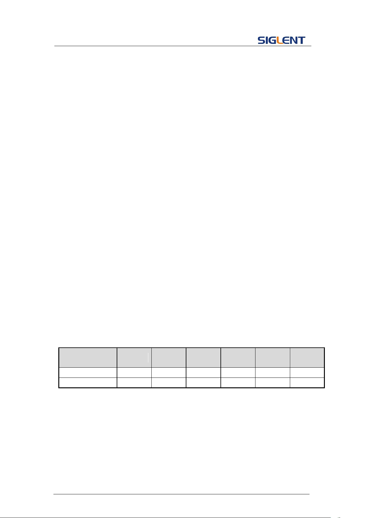
Programming Guide
interpolation method. Sampling rate and interpolation method can only
be set when MODE is TARB.
COMMAND SYNTAX
<channel>:SampleRATE MODE,<mode>,VALUE, <sample
rate>,INTER,<interpolation>
<channel>:= <C1, C2>.
<mode>:= {DDS, TARB}, where TARB is TrueArb.
<sample rate>:= sample rate. The unit is Sa/s.
<interpolation>:= {LINE, HOLD, SINC, SINC27, SINC13}, where LINE
is linear, and HOLD is zero-order hold. SINC, SINC27 and SINC13
are only for SDG6000X/X-E.
QUERY SYNTAX
<channel>:SRATE?
EXAMPLES
Get the sampling rate of CH1:
C1:SRATE?
Return:
C1:SRATE MODE,DDS
Set CH1 to TureArb mode:
C1:SRATE MODE,TARB
Set sampling rate of CH1 to 1000000Sa/s:
C1:SRATE VALUE,1000000
Set CH1 to TureArb mode and set interpolation to SINC13
C1:SRATE MODE,TARB,INTER,SINC13
Parameter
/command
SDG800
SDG1000
SDG2000X
SDG5000
SDG1000X
SDG6000X
/X-E
SRATE
no
no
yes
no
no
yes
INTER
no
no
no
no
no
yes
DESCRIPTION
This command sets or gets the harmonic parameters. Only available
when the basic wave is SINE.
COMMAND SYNTAX
<channel>:HARMonic HARMSTATE,<state>,HARMTYPE,
Note: The table below shows the availability of the command and some parameters in each
SDG series.
3.28 Harmonic Command
49
Page 51
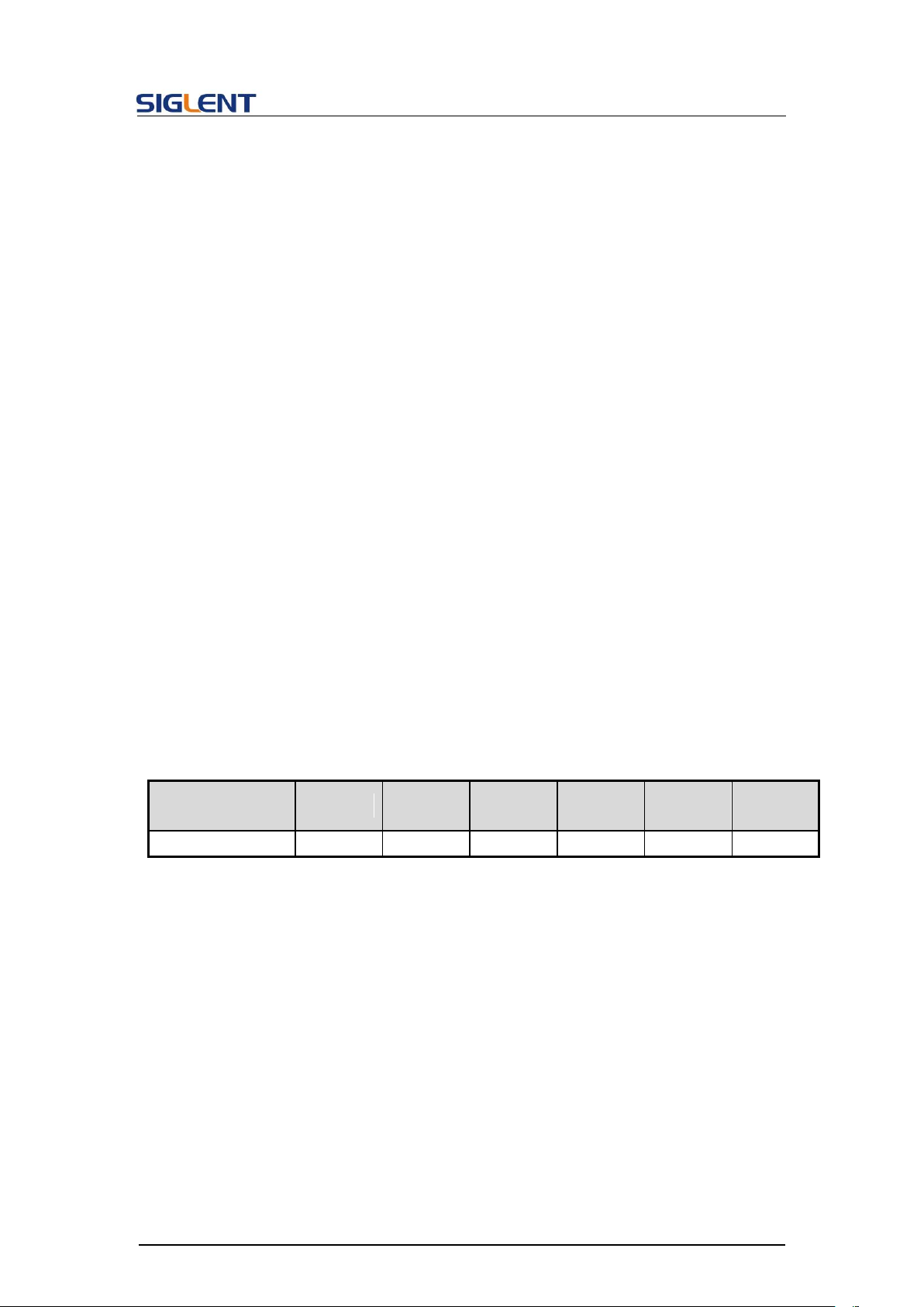
Programming Guide
<type>,HARMORDER,<order>,< unit>,<value>,
HARMPHASE,<phase>
<state>:= <ON, OFF>.
<type>:= <EVEN, ODD, ALL>.
<order>:= {1,2,...,M}, where M is the supported maximum order.
<unit>:= < HARMAMP, HARMDBC>.
<value>:= amplitude of specified harmonic. The range of valid values
depends on the model. When <unit>= HARMAMP, the unit is volts,
peak-to-peak “Vpp”, and when <unit>= HARMDBC, the unit is "dBc".
<phase>:= {0~360}, the unit is "degree"
QUERY SYNTAX
<channel>:(HARMonic?
<channel> : ={C1, C2}.
EXAMPLES
Enable the harmonic function of CH1:
C1:HARM HARMSTATE,ON
Set the 2nd harmonic of CH1 to -6 dBc:
C1:HARM HARMORDER,2,HARMDBC,-6
Get the harmonic information of CH1:
C1:HARM?
Return:
C1:HARM ,HARMSTATE,ON,HARMTYPE,EVEN,HARMORDER,2,H
ARMAMP,2.004748935V,HARMDBC,-6dBc,HARMPHASE,0
Parameter
/command
SDG800
SDG1000
SDG2000X
SDG5000
SDG1000X
SDG6000X
/X-E
HARM
no
no
yes
no
yes
yes
DESCRIPTION
This command sets or gets the waveform combining parameters.
COMMAND SYNTAX
<channel>:CoMBiNe <state>
<channel>:= {C1, C2}.
<state>:= {ON, OFF}.
QUERY SYNTAX
<channel>:CoMBiNe?
<channel>:= {C1, C2}.
Note: The table below shows the availability of the command in each SDG series.
3.29 Waveform Combining Command
50
Page 52
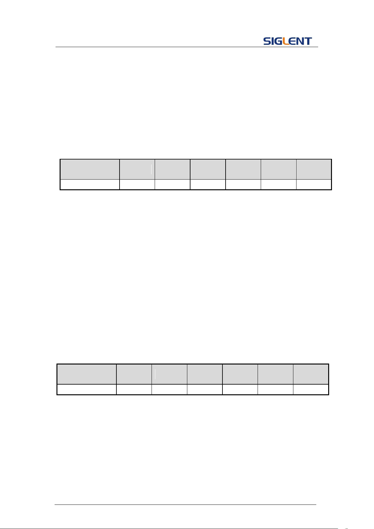
Programming Guide
RESPONSE FORMAT
<channel>:CMBN <state>
EXAMPLES
Turn on the waveform combining of CH1:
C1:CMBN ON
Query the waveform combining state of CH2:
C2:CMBN?
Return:
C2:CMBN OFF
Parameter
/command
SDG800
SDG1000
SDG2000X
SDG5000
SDG1000X
SDG6000X
/X-E
CMBN
no
no
yes
no
yes
yes
DESCRIPTION
This command sets or gets the phase mode.
COMMAND SYNTAX
MODE <parameter>
<parameter>:= {PHASE-LOCKED, INDEPENDENT}.
QUERY SYNTAX
MODE?
RESPONSE FORMAT
MODE <parameter>
EXAMPLE
Set the phase mode to INDEPENDENT:
MODE INDEPENDENT
Parameter
/command
SDG800
SDG1000
SDG2000X
SDG5000
SDG1000X
SDG6000X
/X-E
MODE
no
no
yes
no
yes
yes
DESCRIPTION
This command set up synchronization between two or more
instruments and achieve in-phase output
COMMAND SYNTAX
CASCADE STATE,ON|OFF,MODE,<MODE>,DELAY,<DELAY>
Note: The table below shows the availability of the command in each SDG series.
3.30 Mode Select Command
Note: The table below shows the availability of the command in each SDG series.
3.31 Multi-Device Sync
51
Page 53
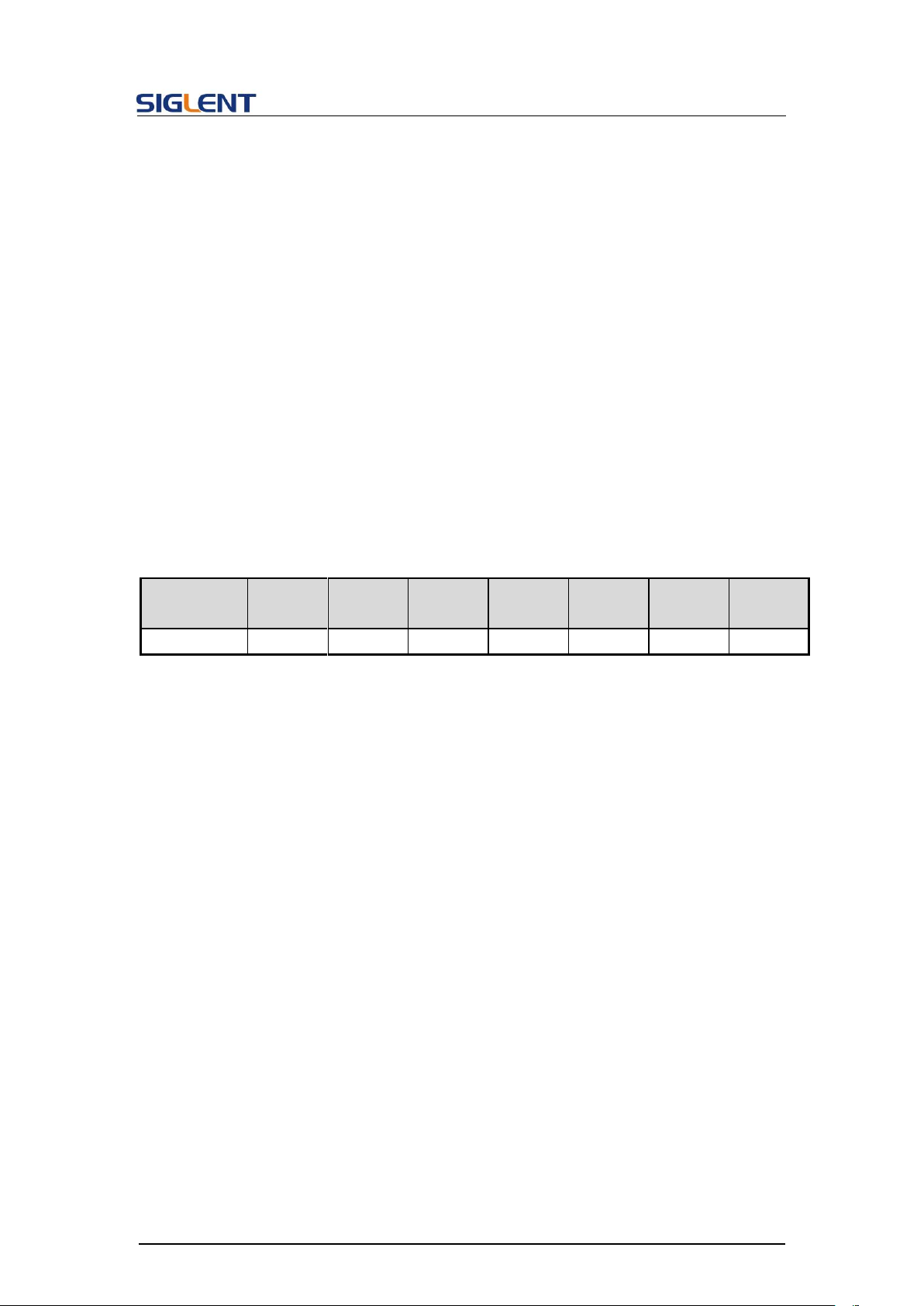
<MODE>:={MASTER,SLAVE}
<DELAY>:={0-0.000025},UNIT=s,This parameter can only be set
in slave mode
QUERY SYNTAX
CASCADE?
RESPONSE FORMAT
Return from SLAVE MODE :
CASCADE STATE,ON,MODE,SLAVE,DELAY, <DELAY>
Return from MASTER mode :
CASCADE STATE,ON,MODE,MASTER
EXAMPLE
Set the device as slave and the delay to 0.0000001s:
CASCADE STATE,ON,MODE,SLAVE,DELAY,0.0000001
Parameter
/command
SDG800
SDG1000
SDG2000
X
SDG5000
SDG1000
X
SDG6000
X
SDG6000
X-E
IQ
no
no
no
no
no
yes
no
DESCRIPTION
This command sets center frequency of the I/Q modulator.
COMMAND SYNTAX
[:SOURce]:IQ:CENTerfreq <center_freq><unit>
<center_freq>:= the center frequency. Refer to the data sheet for
the range of valid values.
<unit>:= {Hz, kHz, MHz, GHz}. The default unit is Hertz “Hz”.
QUERY SYNTAX
[:SOURce]:IQ:CENTerfreq?
RESPONSE FORMAT
<center_freq> (expressed in Hz.)
EXAMPLE
Set the center frequency to 1 kHz:
:SOURce:IQ:CENTerfreq 1000Hz
3.32 IQ Commands
Programming Guide
The table below shows the availability of IQ commands in each SDG series.
3.32.1 :IQ:CENTerfreq
52
Page 54

Programming Guide
DESCRIPTION
This command sets the I/Q sampling rate.
COMMAND SYNTAX
[:SOURce]:IQ:SAMPlerate <sample_rate><unit>
<sample_rate>:= sample rate. Refer to the data sheet for the
range of valid values.
<unit>:= {Hz, kHz, MHz, GHz}. The default unit is Hertz “Hz”.
QUERY SYNTAX
[:SOURce]:IQ:SAMPlerate?
RESPONSE FORMAT
<sample_rate> (expressed in Hz.)
EXAMPLE
Set the sample rate to 100 kHz:
:IQ:SAMPlerate 1000000
or:
:IQ:SAMP 100kHz
DESCRIPTION
This command sets the I/Q symbol rate.
COMMAND SYNTAX
[:SOURce]:IQ:SYMBolrate <symb_rate><unit>
<symb_rate>:= symbol rate. Refer to the data sheet for the range
of valid values.
<unit>:= {S/s, kS/s, MS/s}. The default unit is symbols-per-second
“S/s”.
QUERY SYNTAX
[:SOURce]:IQ:SYMBolrate?
RESPONSE FORMAT
<symb_rate> (expressed in S/s.)
EXAMPLE
Set the symbol rate to 1 MS/s:
:IQ:SYMB 1MS/s
DESCRIPTION
This command sets the I/Q amplitude.
COMMAND SYNTAX
[:SOURce]:IQ:AMPLitude <amplitude><unit>
<amplitude>:= amplitude. Refer to the data sheet for the range of
valid values.
3.32.2 :IQ:SAMPlerate
3.32.3 :IQ:SYMBolrate
3.32.4 :IQ:AMPLitude
53
Page 55

<unit>:= {Vrms, mVrms, dBm}. The default unit is volts, rootmean-square “Vrms”.
QUERY SYNTAX
[:SOURce]:IQ:AMPLitude?
RESPONSE FORMAT
<amplitude> (expressed Vrms.)
EXAMPLE
Set the I/Q amplitude (sqrt(I2+Q2)) to 0.2 Vrms:
:IQ:AMPL 0.2
DESCRIPTION
This command adjusts the ratio of I to Q while preserving the
composite.
COMMAND SYNTAX
[:SOURce]:IQ:IQADjustment:GAIN <gain_ratio>
<gain_ratio>:= Gain ratio of I to Q. The default unit is dB.
QUERY SYNTAX
[:SOURce]:IQ:IQADjustment:GAIN?
RESPONSE FORMAT
<gain_ratio> (expressed in unit of dB.)
EXAMPLE
Set the gain ratio of I/Q to 0.1dB:
:IQ:IQADjustment:GAIN 0.1
DESCRIPTION
This command adjusts the I channel offset value.
COMMAND SYNTAX
[:SOURce]:IQ:IQADjustment:IOFFset <offset><unit>
<offset>:= I offset.
<unit>:= {V, mV, uV}. The default unit is volts “V”.
QUERY SYNTAX
[:SOURce]:IQ:IQADjustment:IOFFset?
RESPONSE FORMAT
<offset> (expressed V.)
EXAMPLE
Set the I offset to 1 mV:
:IQ:IQADjustment:IOFFset 1mV
3.32.5 :IQ:IQADjustment:GAIN
Programming Guide
3.32.6 :IQ:IQADjustment:IOFFset
54
Page 56

Programming Guide
DESCRIPTION
This command adjusts the Q channel offset value.
COMMAND SYNTAX
[:SOURce]:IQ:IQADjustment:QOFFset <offset><unit>
<offset>:= Q offset.
<unit>:= {V, mV, uV}. The default unit is volts “V”.
QUERY SYNTAX
[:SOURce]:IQ:IQADjustment:QOFFset?
RESPONSE FORMAT
<offset> (expressed in V.)
EXAMPLE
Set the Q offset to -1 mV:
:IQ:IQAD:QOFF -0.001V
DESCRIPTION
This command adjusts the phase angle (quadrature skew)
between the I and Q vectors by increasing or decreasing the
Q phase angle.
COMMAND SYNTAX
[:SOURce]:IQ:IQADjustment:QSKew <angle>
<angle>:= angle. The unit is degree.
QUERY SYNTAX
[:SOURce]:IQ:IQADjustment:QSKew?
RESPONSE FORMAT
<angle> (expressed in unit of degree.)
EXAMPLE
Set the Q angle to 1 degree:
:IQ:IQADjustment:QSKew 1.0
DESCRIPTION
This command sets the I/Q trigger source.
COMMAND SYNTAX
[:SOURce]:IQ:TRIGger:SOURce <src>
<src>:={INTernal,EXTernal,MANual}
QUERY SYNTAX
[:SOURce]:IQ:TRIGger:SOURce?
RESPONSE FORMAT
<src>
3.32.7 :IQ:IQADjustment:QOFFset
3.32.8 :IQ:IQADjustment:QSKew
3.32.9 :IQ:TRIGger:SOURce
55
Page 57
EXAMPLE
Set the trigger source to INT:
:IQ:TRIGger:SOURce INTernal
DESCRIPTION
This command selects I/Q waveform from the built in waveform
list.
COMMAND SYNTAX
[:SOURce]:IQ:WAVEload:BUILtin <wave_name>
<wave_name>:= {A waveform name from the table below}.
QUERY SYNTAX
[:SOURce]:IQ:WAVEload?
RESPONSE FORMAT
BUILtin|USERstored <wave_name>
EXAMPLE
Set the I/Q waveform to built-in 2ASK:
:IQ:WAVE:BUIL 2ASK
2ASK
4ASK
8ASK
BPSK
4PSK
8PSK
DBPSK
4DPSK
8DPSK
8QAM
16QAM
32QAM
64QAM
128QAM
256QAM
DESCRIPTION
This command selects I/Q waveform from the user stored
waveforms.
COMMAND SYNTAX
[:SOURce]:IQ:WAVEload:USERstored “<wave_name>”
<wave_name>:= { A waveform name from the user stored
waveforms}.
QUERY SYNTAX
[:SOURce]:IQ:WAVEload?
RESPONSE FORMAT
BUILtin|USERstored <wave_name>
EXAMPLE
Set the I/Q waveform to user stored UserIQ_1.arb:
:IQ:WAVEload:USERstored “UserIQ_1.arb”
3.32.10 :IQ:WAVEload:BUILtin
Programming Guide
3.32.11 :IQ:WAVEload:USERstored
56
Page 58

Programming Guide
DESCRIPTION
This command sets the I/Q Frequency sampling rate.
COMMAND SYNTAX
[:SOURce]:IQ: FrequencySampling <sampling>
< sampling >:= {500-300000000}. The unit is S/s
QUERY SYNTAX
[:SOURce]:IQ:FrequencySampling?
[:SOURce]:IQ:FrequencySamplingLimit?
RESPONSE FORMAT
<sampling>
MAX,<max_sampling>,MIN,< min_sampling >
EXAMPLE
Set the I/Q frequency sampling to 2000000:
:IQ:FrequencySampling 2000000
3.32.12 :IQ:FrequencySampling
57
Page 59

Programming Guide
4 Programming Examples
This chapter gives some examples for the programmer. In these examples you can see
how to use VISA or sockets, in combination with the commands described above to control
the generator. By following these examples, you can develop many more applications.
4.1 Examples of Using VISA
4.1.1 VC++ Example
Environment: Windows 7 32-bit, Visual Studio.
Description: Query the instrument information using "*IDN?" command over NI-VISA,
with the access through USBTMC and TCP/IP separately.
Steps:
1. Open Visual Studio, create a new VC++ win32 console project.
2. Set the project environment to use the NI-VISA lib, there are two ways to specify
NI-VISA, static or automatic:
a) Static:
Find the files visa.h, visatype.h and visa32.lib in NI-VISA installation path, copy
them to the root path of the VC++ project, and add them into the project. In the
projectname.cpp file, add the following two lines:
#include "visa.h"
#pragma comment(lib,"visa32.lib")
b) Dynamic:
In "project---properties---c/c++---General---Additional Include Directories" set
the value to the NI-VISA installation path (e.g. C:\Program Files\IVI
Foundation\VISA\WinNT\include), as shown in the figure below:
58
Page 60
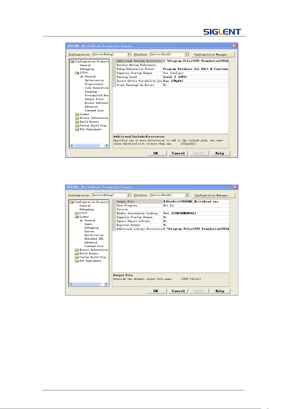
Programming Guide
In " project---properties---Linker---General---Additional Library Directories " set
the value to the NI-VISA installation path (e.g. C:\Program Files\IVI
Foundation\VISA\WinNT\include), as shown in the figure below:
In "project---properties---Linker---Command Line---Additional" set the value to
visa32.lib, as shown in the figure below:
59
Page 61
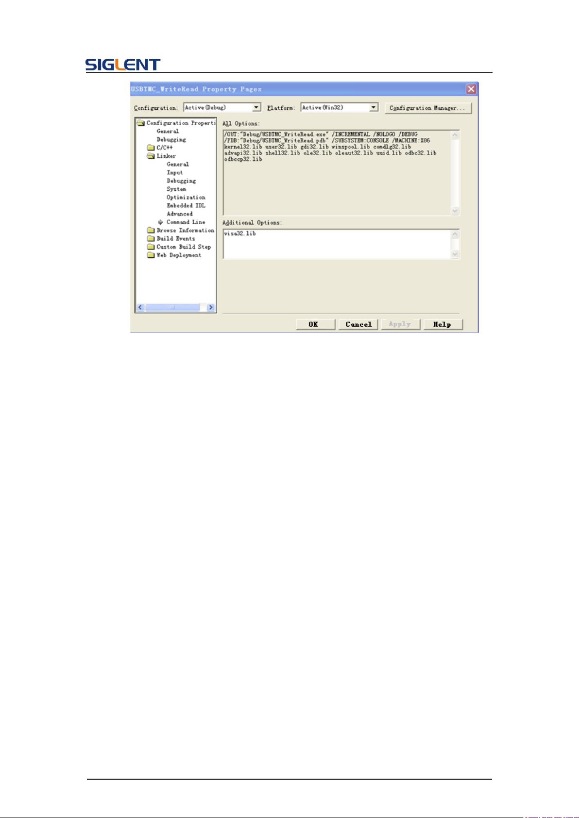
Programming Guide
Include visa.h file in the projectname.cpp file:
3. Coding:
a) USBTMC:
int Usbtmc_test()
{
/* This code demonstrates sending synchronous read & write commands */
/* to an USB Test & Measurement Class (USBTMC) instrument using */
/* NI-VISA */
/* The example writes the "*IDN?\n" string to all the USBTMC */
/* devices connected to the system and attempts to read back */
/* results using the write and read functions. */
/* The general flow of the code is */
/* Open Resource Manager */
/* Open VISA Session to an Instrument */
/* Write the Identification Query Using viPrintf */
/* Try to Read a Response With viScanf */
/* Close the VISA Session */
/***********************************************************/
ViSession defaultRM;
ViSession instr;
#include <visa.h>
60
Page 62

Programming Guide
ViUInt32 numInstrs;
ViFindList findList;
ViStatus status;
char instrResourceString[VI_FIND_BUFLEN];
unsigned char buffer[100];
int i;
/** First we must call viOpenDefaultRM to get the manager
* handle. We will store this handle in defaultRM.*/
status=viOpenDefaultRM (&defaultRM);
if (status<VI_SUCCESS)
{
printf ("Could not open a session to the VISA Resource Manager!\n");
return status;
}
/* Find all the USB TMC VISA resources in our system and store the number of
resources in the system in numInstrs. */
status = viFindRsrc (defaultRM, "USB?*INSTR", &findList, &numInstrs,
instrResourceString);
if (status<VI_SUCCESS)
{
printf ("An error occurred while finding resources.\nPress 'Enter' to
continue.");
fflush(stdin);
getchar();
viClose (defaultRM);
return status;
}
/** Now we will open VISA sessions to all USB TMC instruments.
* We must use the handle from viOpenDefaultRM and we must
* also use a string that indicates which instrument to open. This
* is called the instrument descriptor. The format for this string
* can be found in the function panel by right clicking on the
* descriptor parameter. After opening a session to the
* device, we will get a handle to the instrument which we
* will use in later VISA functions. The AccessMode and Timeout
* parameters in this function are reserved for future
* functionality. These two parameters are given the value VI_NULL.*/
for (i=0; i<int(numInstrs); i++)
{
if (i> 0)
{
viFindNext (findList, instrResourceString);
}
status = viOpen (defaultRM, instrResourceString, VI_NULL, VI_NULL,
61
Page 63

Programming Guide
&instr);
if (status<VI_SUCCESS)
{
printf ("Cannot open a session to the device %d.\n", i+1);
continue;
}
/* * At this point we now have a session open to the USB TMC instrument.
* We will now use the viPrintf function to send the device the string
"*IDN?\n",
* asking for the device's identification. */
char * cmmand ="*IDN?\n";
status = viPrintf (instr, cmmand);
if (status<VI_SUCCESS)
{
printf ("Error writing to the device %d.\n", i+1);
status = viClose (instr);
continue;
}
/** Now we will attempt to read back a response from the device to
* the identification query that was sent. We will use the viScanf
* function to acquire the data.
* After the data has been read the response is displayed.*/
status = viScanf(instr, "%t", buffer);
if (status<VI_SUCCESS)
{
printf ("Error reading a response from the device %d.\n", i+1);
}
else
{
printf ("\nDevice %d: %s\n", i+1 , buffer);
}
status = viClose (instr);
}
/** Now we will close the session to the instrument using
* viClose. This operation frees all system resources. */
status = viClose (defaultRM);
printf("Press 'Enter' to exit.");
fflush(stdin);
getchar();
return 0;
}
int _tmain(int argc, _TCHAR* argv[])
62
Page 64
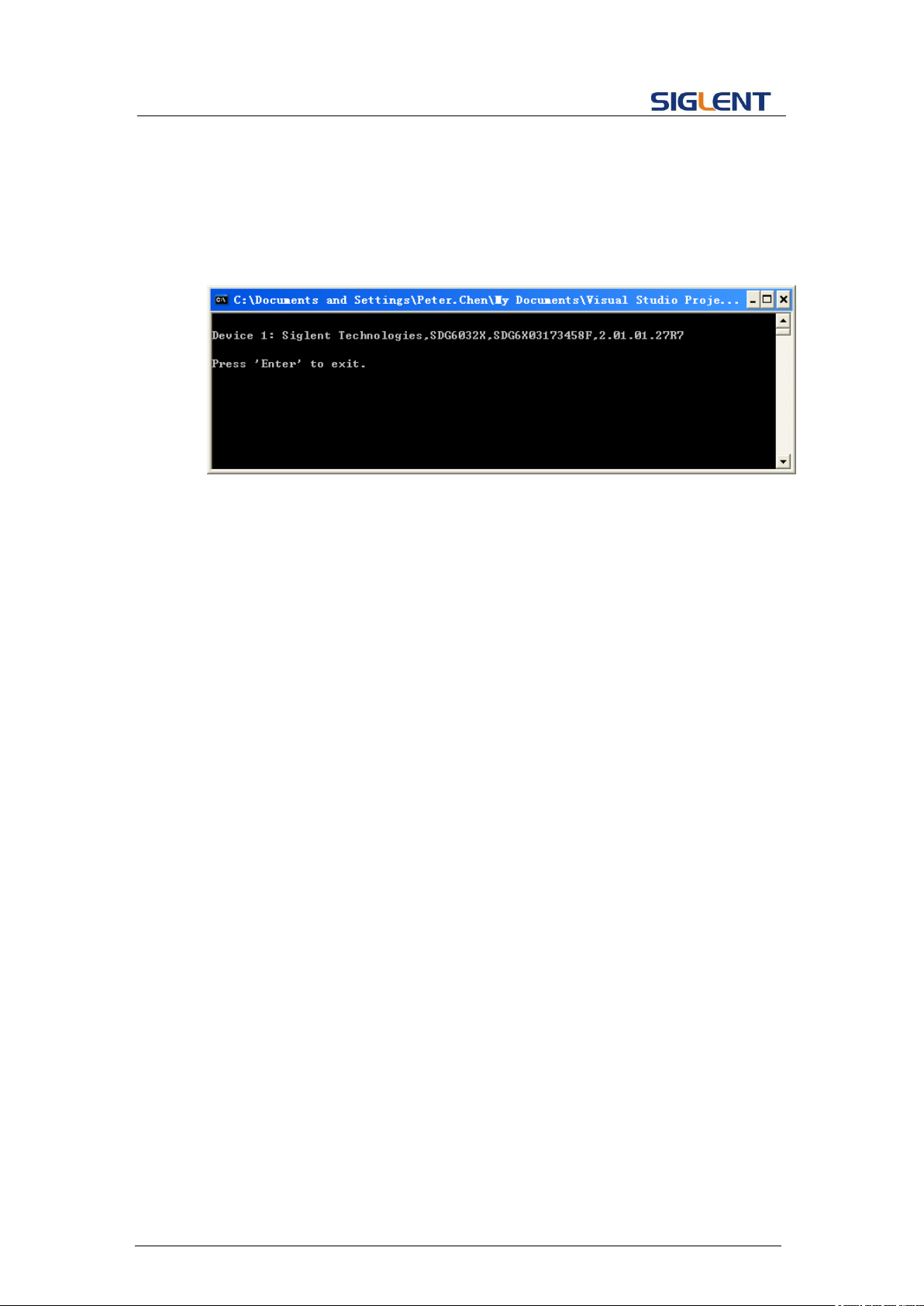
Programming Guide
{
Usbtmc_test();
return 0;
}
Run result:
b) TCP/IP:
int TCP_IP_Test(char *pIP)
{
char outputBuffer[VI_FIND_BUFLEN];
ViSession defaultRM, instr;
ViStatus status;
/* First we will need to open the default resource manager. */
status = viOpenDefaultRM (&defaultRM);
if (status<VI_SUCCESS)
{
printf("Could not open a session to the VISA Resource Manager!\n");
}
/* Now we will open a session via TCP/IP device */
char head[256] ="TCPIP0::";
char tail[] ="::INSTR";
strcat(head,pIP);
strcat(head,tail);
status = viOpen (defaultRM, head, VI_LOAD_CONFIG, VI_NULL, &instr);
if (status<VI_SUCCESS)
{
printf ("An error occurred opening the session\n");
viClose(defaultRM);
}
status = viPrintf(instr, "*idn?\n");
status = viScanf(instr, "%t", outputBuffer);
if (status<VI_SUCCESS)
63
Page 65
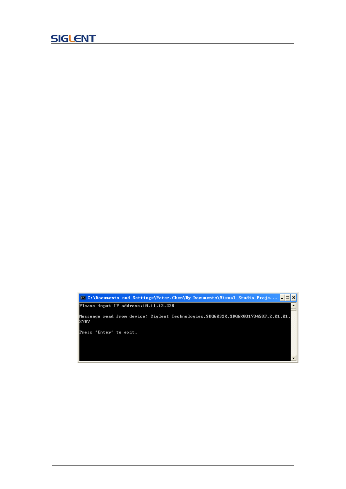
Programming Guide
{
printf("viRead failed with error code: %x \n",status);
viClose(defaultRM);
}
else
{
printf ("\nMesseage read from device: %*s\n", 0,outputBuffer);
}
status = viClose (instr);
status = viClose (defaultRM);
printf("Press 'Enter' to exit.");
fflush(stdin);
getchar();
return 0;
}
int _tmain(int argc, _TCHAR* argv[])
{
printf("Please input IP address:");
char ip[256];
fflush(stdin);
gets(ip);
TCP_IP_Test(ip);
return 0;
}
Run result:
64
Page 66
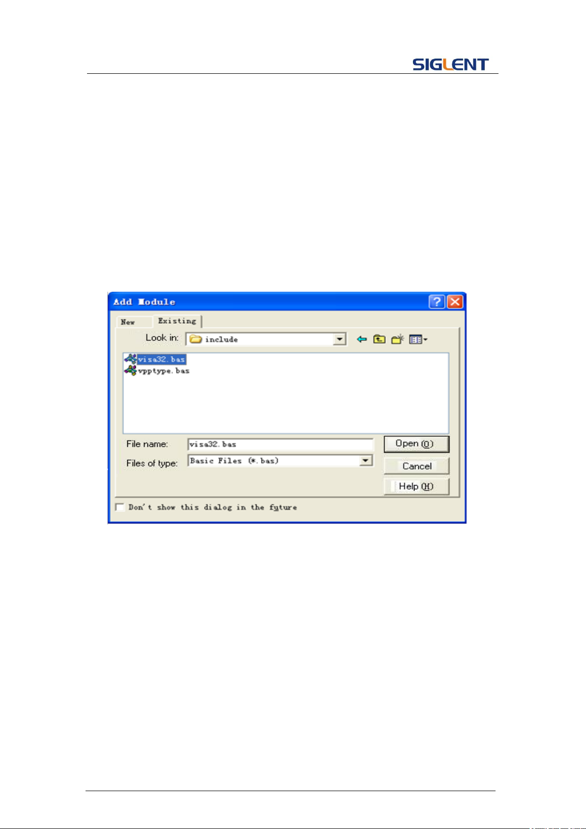
Programming Guide
4.1.2 VB Example
Environment: Windows 7 32-bit, Microsoft Visual Basic 6.0
Description: Query the instrument information using "IDN?" command over NI-VISA,
with the access through USBTMC and TCP/IP separately.
Steps:
1. Open Visual Basic, and build a standard application program project.
2. Set the project environment to use the NI-VISA lib: Click the Existing tab of
Project>>Add Existing Item, search the visa32.bas file in the "include" folder under
the NI-VISA installation path and add the file, as shown in the figure below:
3. Coding:
a) USBTMC:
Private Function Usbtmc_test() As Long
' This code demonstrates sending synchronous read & write commands
' to an USB Test & Measurement Class (USBTMC) instrument using
' NI-VISA
' The example writes the "*IDN?\n" string to all the USBTMC
' devices connected to the system and attempts to read back
' results using the write and read functions.
' The general flow of the code is
' Open Resource Manager
' Open VISA Session to an Instrument
65
Page 67

Programming Guide
' Write the Identification Query Using viWrite
' Try to Read a Response With viRead
' Close the VISA Session
Const MAX_CNT = 200
Dim defaultRM As Long
Dim instrsesn As Long
Dim numlnstrs As Long
Dim findList As Long
Dim retCount As Long
Dim status As Long
Dim instrResourceString As String * VI_FIND_BUFLEN
Dim Buffer As String * MAX_CNT
Dim i As Integer
' First we must call viOpenDefaultRM to get the manager
' handle. We will store this handle in defaultRM.
status = viOpenDefaultRM(defaultRM)
If (status < VI_SUCCESS) Then
resultTxt.Text = "Could not open a session to the VISA Resource Manager!"
Usbtmc_test = status
Exit Function
End If
' Find all the USB TMC VISA resources in our system and store the
' number of resources in the system in numInstrs.
status = viFindRsrc(defaultRM, "USB?*INSTR", findList, numlnstrs, instrResourceString)
If (status < VI_SUCCESS) Then
resultTxt.Text = "An error occurred while finding resources."
viClose(defaultRM)
Usbtmc_test = status
Exit Function
End If
' Now we will open VISA sessions to all USB TMC instruments.
' We must use the handle from viOpenDefaultRM and we must
' also use a string that indicates which instrument to open. This
' is called the instrument descriptor. The format for this string
' can be found in the function panel by right clicking on the
' descriptor parameter. After opening a session to the
' device, we will get a handle to the instrument which we
' will use in later VISA functions. The AccessMode and Timeout
' parameters in this function are reserved for future
' functionality. These two parameters are given the value VI_NULL.
66
Page 68

Programming Guide
For i = 0 To numInstrs
If (i > 0) Then
status = viFindNext(findList, instrResourceString)
End If
status = viOpen(defaultRM, instrResourceString, VI_NULL, VI_NULL, instrsesn)
If (status < VI_SUCCESS) Then
resultTxt.Text = "Cannot open a session to the device " + CStr(i + 1)
GoTo NextFind
End If
' At this point we now have a session open to the USB TMC instrument.
' We will now use the viWrite function to send the device the string "*IDN?",
' asking for the device's identification.
status = viWrite(instrsesn, "*IDN?", 5, retCount)
If (status < VI_SUCCESS) Then
resultTxt.Text = "Error writing to the device."
status = viClose(instrsesn)
GoTo NextFind
End If
' Now we will attempt to read back a response from the device to
' the identification query that was sent. We will use the viRead
' function to acquire the data.
' After the data has been read the response is displayed.
status = viRead(instrsesn, Buffer, MAX_CNT, retCount)
If (status < VI_SUCCESS) Then
resultTxt.Text = "Error reading a response from the device." + CStr(i + 1)
Else
resultTxt.Text = "Read from device: " + CStr(i + 1) + " " + Buffer
End If
status = viClose(instrsesn)
Next i
' Now we will close the session to the instrument using
' viClose. This operation frees all system resources.
status = viClose(defaultRM)
Usbtmc_test = 0
End Function
b) TCP/IP:
Private Function TCP_IP_Test(ByVal ip As String) As Long
Dim outputBuffer As String * VI_FIND_BUFLEN
67
Page 69

Programming Guide
Dim defaultRM As Long
Dim instrsesn As Long
Dim status As Long
Dim count As Long
' First we will need to open the default resource manager.
status = viOpenDefaultRM(defaultRM)
If (status < VI_SUCCESS) Then
resultTxt.Text = "Could not open a session to the VISA Resource Manager!"
TCP_IP_Test = status
Exit Function
End If
' Now we will open a session via TCP/IP device
status = viOpen(defaultRM, "TCPIP0::" + ip + "::INSTR", VI_LOAD_CONFIG, VI_NULL,
instrsesn)
If (status < VI_SUCCESS) Then
resultTxt.Text = "An error occurred opening the session"
viClose(defaultRM)
TCP_IP_Test = status
Exit Function
End If
status = viWrite(instrsesn, "*IDN?", 5, count)
If (status < VI_SUCCESS) Then
resultTxt.Text = "Error writing to the device."
End If
status = viRead(instrsesn, outputBuffer, VI_FIND_BUFLEN, count)
If (status < VI_SUCCESS) Then
resultTxt.Text = "Error reading a response from the device." + CStr(i + 1)
Else
resultTxt.Text = "read from device:" + outputBuffer
End If
status = viClose(instrsesn)
status = viClose(defaultRM)
TCP_IP_Test = 0
End Function
c) Button control code:
Private Sub exitBtn_Click()
End
68
Page 70
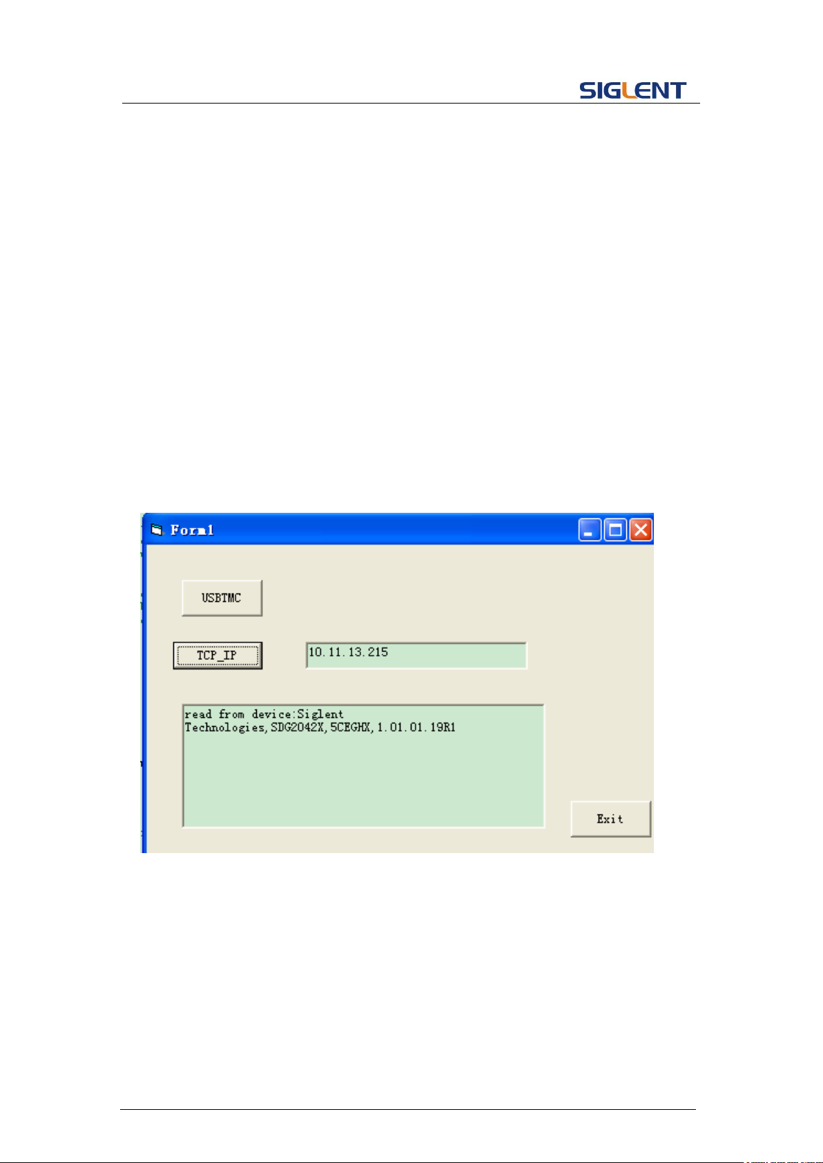
Programming Guide
End Sub
Private Sub tcpipBtn_Click()
Dim stat As Long
stat = TCP_IP_Test(ipTxt.Text)
If (stat < VI_SUCCESS) Then
resultTxt.Text = Hex(stat)
End If
End Sub
Private Sub usbBtn_Click()
Dim stat As Long
stat = Usbtmc_test
If (stat < VI_SUCCESS) Then
resultTxt.Text = Hex(stat)
End If
End Sub
Run result:
69
Page 71

Programming Guide
4.1.3 MATLAB Example
Environment: Windows 7 32-bit, MATLAB R2013a
Description: Query the instrument information using "IDN?" command over NI-VISA,
with the access through USBTMC and TCP/IP separately.
Steps:
1. Open MATLAB, and modify the current directory. In this demo, the current directory
is modified to "D:\USBTMC_TCPIP_Demo".
2. Click File>>New>>Script in the Matlab interface to create an empty M file.
3. Coding:
a) USBTMC:
function USBTMC_test()
% This code demonstrates sending synchronous read & write commands
% to an USB Test & Measurement Class (USBTMC) instrument using
% NI-VISA
%Create a VISA-USB object connected to a USB instrument
vu = visa('ni','USB0::0xF4ED::0xEE3A::sdg2000x::INSTR');
%Open the VISA object created
fopen(vu);
%Send the string "*IDN?",asking for the device's identification.
fprintf(vu,'*IDN?');
%Request the data
outputbuffer = fscanf(vu);
disp(outputbuffer);
%Close the VISA object
fclose(vu);
delete(vu);
clear vu;
end
70
Run result:
Page 72
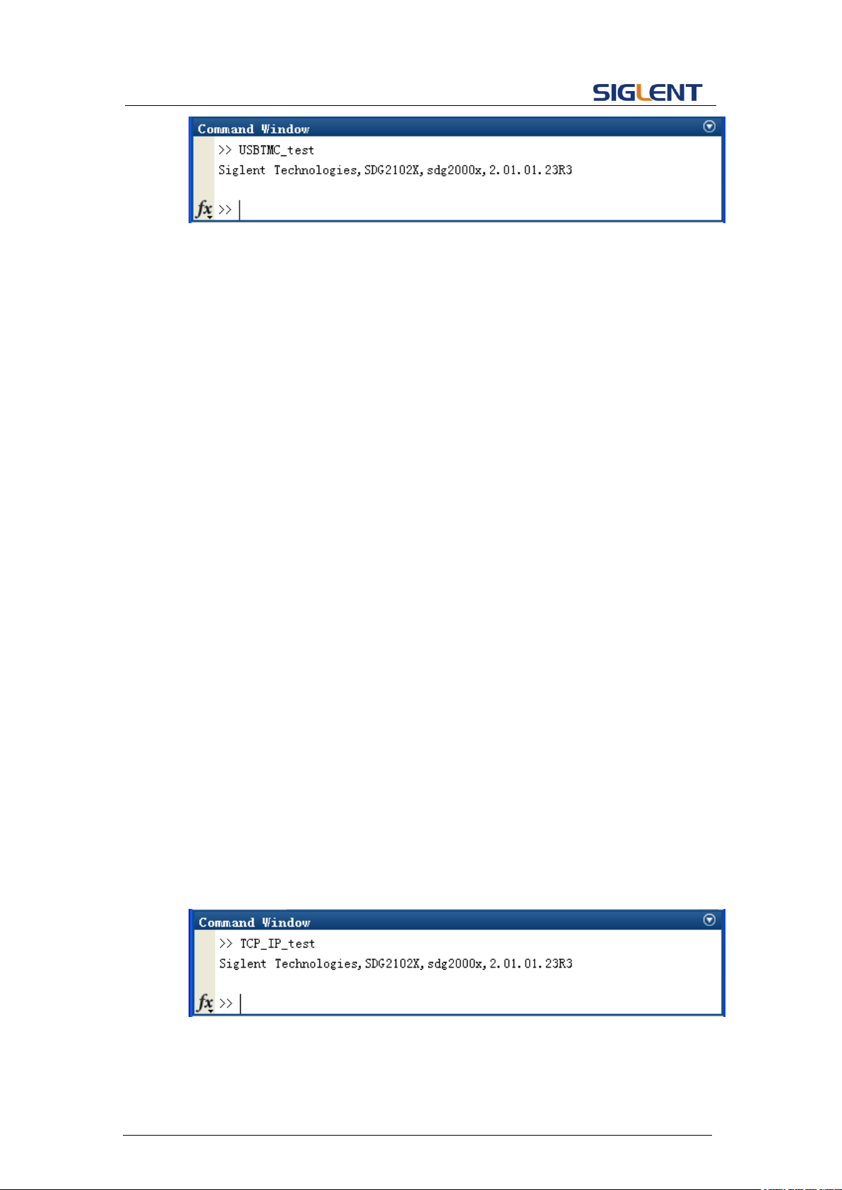
Programming Guide
b) TCP/IP:
Write a function TCP_IP_Test:
function TCP_IP_test()
% This code demonstrates sending synchronous read & write commands
% to an TCP/IP instrument using NI-VISA
%Create a VISA-TCPIP object connected to an instrument
%configured with IP address.
vt = visa('ni',['TCPIP0::','10.11.13.32','::INSTR']);
%Open the VISA object created
fopen(vt);
%Send the string "*IDN?",asking for the device's identification.
fprintf(vt,'*IDN?');
%Request the data
outputbuffer = fscanf(vt);
disp(outputbuffer);
%Close the VISA object
fclose(vt);
delete(vt);
clear vt;
end
Run result:
71
Page 73
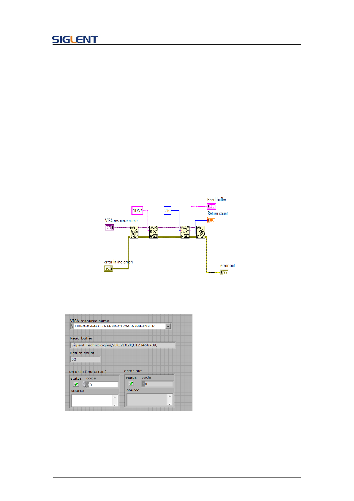
Programming Guide
4.1.4 LabVIEW Example
Environment: Windows 7 32-bit, LabVIEW 2011
Description: Query the instrument information using "IDN?" command over NI-VISA,
with the access through USBTMC and TCP/IP separately.
Steps:
1. Open LabVIEW, and create a VI file.
2. Add controls. Right-click in the Front Panel interface, select and add VISA
resource name, error in, error out and some indicators from the Controls column.
3. Open the Block Diagram interface. Right-click on the VISA resource name,
select and add the following functions from VISA Palette from the pop-up menu:
VISA Write, VISA Read, VISA Open and VISA Close.
4. The connection is as shown in the figure below:
5. Select the device resource from the VISA Resource Name list box and run the
program.
In this example, the VI opens a VISA session to a USBTMC device, writes a "IDN?"
command to the device, and reads back the response. After all communication is
complete, the VI closes the VISA session.
72
Page 74
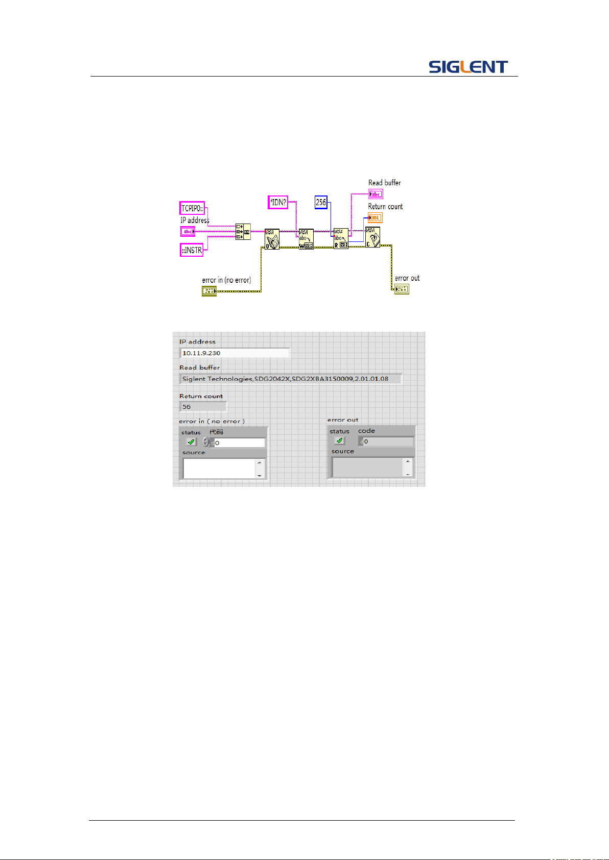
Programming Guide
6. Communicating with the device via TCP/IP is similar to USBTMC. But you need to
change VISA Write and VISA Read Function to Synchronous I/O. The LabVIEW
default is asynchronous I/O. Right-click the node and select Synchronous I/O
Mod>>Synchronous from the shortcut menu to write or read data synchronously.
7. The connection is as shown in the figure below:
8. Input the IP address and run the program.
73
Page 75

Programming Guide
4.1.5 Python Example
Environment: Python2.7, PyVISA 1.4
(Please install PyVISA after installing Python2.7. Please refer to
https://pyvisa.readthedocs.io/en/stable/getting.html for PyVISA installation guide.
Description: Use Python script to build an 8-point 16-bit arbitrary waveform (0x1000,
0x2000, 0x3000, 0x4000, 0x5000, 0x6000, 0x7000, 0x7fff) and save the waveform
data in "wave1.bin", then download it to the instrument, finally read it back from the
instrument and save it as "wave2.bin".
Below is the code of the script:
#!/usr/bin/env python2.7
# -*- coding: utf-8 -*-
import visa
import time
import binascii
#USB resource of Device
device_resource = "USB0::0xF4EC::0x1101::#15::INSTR"
#Little endian, 16-bit 2's complement
wave_points = [0x0010, 0x0020, 0x0030, 0x0040, 0x0050, 0x0060, 0x0070, 0xff7f]
def create_wave_file():
"""create a file"""
f = open("wave1.bin", "wb")
for a in wave_points:
b = hex(a)
b = b[2:]
len_b = len(b)
if (0 == len_b):
b = '0000'
elif (1 == len_b):
b = '000' + b
elif (2 == len_b):
b = '00' + b
elif (3 == len_b):
74
Page 76

Programming Guide
b = '0' + b
c = binascii.a2b_hex(b) #Hexadecimal integer to ASCii encoded string
f.write(c)
f.close()
def send_wawe_data(dev):
"""send wave1.bin to the device"""
f = open("wave1.bin", "rb") #wave1.bin is the waveform to be sent
data = f.read()
print 'write bytes:',len(data)
dev.write("C1:WVDT
WVNM,wave1,FREQ,2000.0,AMPL,4.0,OFST,0.0,PHASE,0.0,WAVEDATA,%s" % (data))
#"X" series (SDG1000X/SDG2000X/SDG6000X/X-E)
dev.write("C1:ARWV NAME,wave1")
f.close()
def get_wave_data(dev):
"""get wave from the devide"""
f = open("wave2.bin", "wb") #save the waveform as wave2.bin
dev.write("WVDT? user,wave1") #"X" series (SDG1000X/SDG2000X/SDG6000X/X-E)
time.sleep(1)
data = dev.read()
data_pos = data.find("WAVEDATA,") + len("WAVEDATA,")
print data[0:data_pos]
wave_data = data[data_pos:]
print 'read bytes:',len(wave_data)
f.write(wave_data)
f.close()
if __name__ == '__main__':
""""""
device = visa.instrument(device_resource, timeout=5000, chunk_size = 40*1024)
create_wave_file()
send_wawe_data(device)
get_wave_data(device)
Output waveform:
75
Page 77
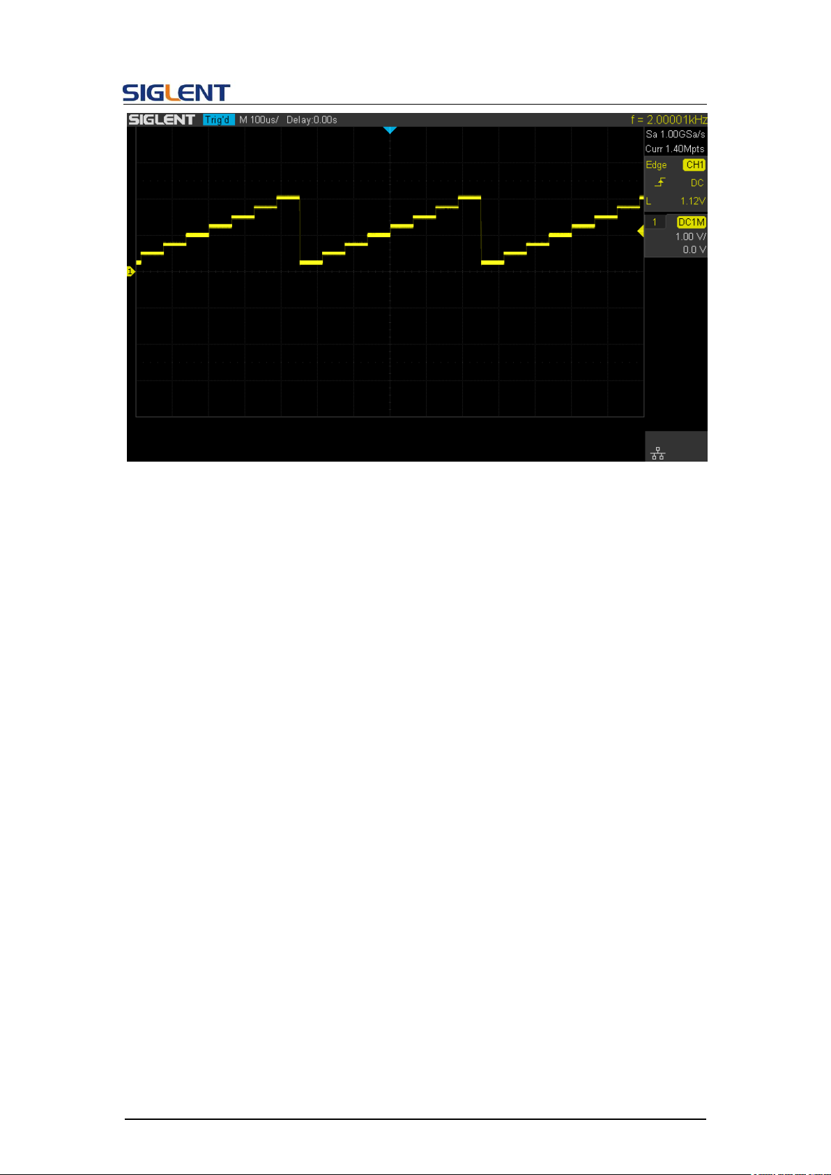
Programming Guide
76
Page 78

Programming Guide
4.2 Examples of Using Sockets
4.2.1 Python Example
Python has a low-level networking module that provides access to the socket interface.
Python scripts can be written for sockets to do a variety of tests and measurement tasks.
Environment: Windows 7 32-bit, Python v2.7.5
Description: Open a socket, send a query, and repeat this loop for 10 times, finally close
the socket. Note that SCPI command strings must be terminated with a “\n” (new line)
character in programming.
Below is the code of the script:
#!/usr/bin/env python
#-*- coding:utf-8 –*#----------------------------------------------------------------------------# The short script is a example that open a socket, sends a query,
# print the return message and closes the socket.
#-----------------------------------------------------------------------------
import socket # for sockets
import sys # for exit
import time # for sleep
#-----------------------------------------------------------------------------
remote_ip = "10.11.13.40" # should match the instrument’s IP address
port = 5025 # the port number of the instrument service
count = 0
def SocketConnect():
try:
#create an AF_INET, STREAM socket (TCP)
s = socket.socket(socket.AF_INET, socket.SOCK_STREAM)
except socket.error:
print ('Failed to create socket.')
sys.exit();
try:
#Connect to remote server
s.connect((remote_ip , port))
except socket.error:
print ('failed to connect to ip ' + remote_ip)
77
Page 79

Programming Guide
return s
def SocketQuery(Sock, cmd):
try :
#Send cmd string
Sock.sendall(cmd)
time.sleep(1)
except socket.error:
#Send failed
print ('Send failed')
sys.exit()
reply = Sock.recv(4096)
return reply
def SocketClose(Sock):
#close the socket
Sock.close()
time.sleep(.300)
def main():
global remote_ip
global port
global count
# Body: send the SCPI commands *IDN? 10 times and print the return message
s = SocketConnect()
for i in range(10):
qStr = SocketQuery(s, b'*IDN?\n')
print (str(count) + ":: " + str(qStr))
count = count + 1
SocketClose(s)
input('Press "Enter" to exit')
if __name__ == '__main__':
proc = main()
Run result:
78
Page 80
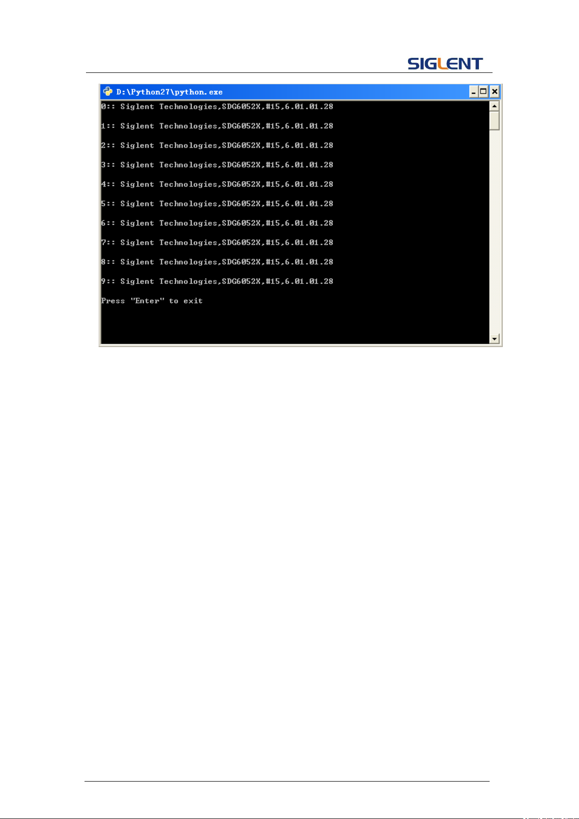
Programming Guide
79
Page 81

5 Index
*IDN
*OPC
*RST
A
ARWV ArbWaVe
B
BSWV BaSic_WaVe
BTWV BursTWaVe
BUZZ BUZZer
C
CASCADE
CHDR Comm_HeaDeR
COUP COUPling
CMBN CoMBiNe
F
FCNT FreqCouNTer
H
HARM HARMonic
I
IQ:CENT IQ:CENTerfreq
IQ:SAMP IQ:SAMPlerate
IQ:SYMB IQ:SYMBolrate
IQ:AMPL IQ:AMPLitude
IQ:IQAD:GAIN IQ:IQADjustment:GAIN
IQ:IQAD:IOFFset IQ:IQADjustment:IOFFset
IQ:IQAD:QOFFset IQ:IQADjustment:QOFFset
IQ:IQAD:QSK IQ:IQADjustment:QSKew
IQ:TRIG:SOUR IQ:TRIGger:SOURce
IQ:WAVE:BUIL IQ:WAVEload:BUILtin
IQ:WAVE:USER IQ:WAVEload:USERstored
IQ:FrequencySampling IQ:FrequencySampling
IVNT INVERT
L
Programming Guide
80
Page 82

Programming Guide
LAGG LAnGuaGe
M
MDWV MoDulateWaVe
MODE MODE
N
NBFM NumBer_ForMat
O
OUTP OUTPut
P
PACP ParaCoPy
R
ROSC ROSCillator
S
SCFG Sys_CFG
SCSV SCreen_SaVe
SWWV SweepWaVe
SYNC SYNC
STL StoreList
SYST:COMM:LAN:IPAD SYSTem:COMMunicate:LAN:IPADdress
SYST:COMM:LAN:SMAS SYSTem:COMMunicate:LAN:SMASk
SYST:COMM :LAN:GAT SYSTem:COMMunicate:LAN:GATeway
SRATE SampleRATE
W
WVDT WVDT
V
VOLTPRT VOLTPRT
VKEY VirtualKEY
81
Page 83
Programming Guide
82
 Loading...