

Sigineer Power Solar Mate Installation & Operation Manual
MATRIX Inverter System User Manual
Shenzhen Sigineer Power CO.,LTD.
Email: info@sigineer.com
TEL: +86 755 2160 7078
FAX: +86 755 6165 8278
Add: Bld A, Jiali Industrial Zone, Yuanfen Rd, Longhua, Shenzhen, 518100, China
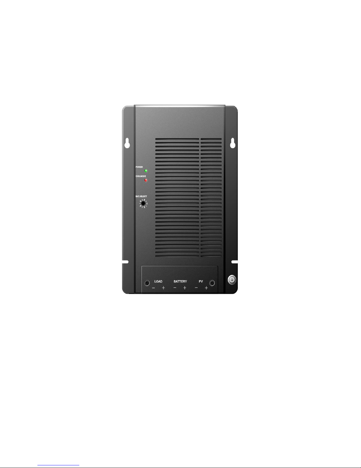
Solar Mate MPPT Solar Charger
Controller
Installation & Operation Manual

www.sigineer.com MATRIX Inverter System User Manual
- 2 -
Contents
Important safety instructions ................................................................................................................................. 6
1. Product description ............................................................................................................................................. 8
1.1 General description ...................................................................................................................................... 8
1.2 Features ........................................................................................................................................................ 8
1.3 Maximum setpoint voltage limit .................................................................................................................. 9
1.4 Temperature and output power .................................................................................................................... 9
1.5 Maximum power point tracking (MPPT) .................................................................................................... 9
1.6 How MPPT works ....................................................................................................................................... 9
1.7 Over voltage / reverse polarity protection ................................................................................................. 10
1.8 Electrostatic handling precautious ............................................................................................................. 10
1.9 Solar charger controller setup .................................................................................................................... 10
1.9.1 Factory default settings ................................................................................................................... 10
1.10 Three stage charge control ....................................................................................................................... 10
1.10.1 Bulk charge ................................................................................................................................... 10
1.10.2 Absorption charge ..........................................................................................................................11
1.10.3 Float charge....................................................................................................................................11
1.11 Battery temperature sensor (BTS) ........................................................................................................... 11
1.12 Equalization charge ................................................................................................................................. 11
1.12.1 Photovoltaic charge and load controller .........................................................................................11
1.12.2 Automatic PV array night disconnect ........................................................................................... 12
1.12.3 Solar charger controller load control ............................................................................................ 12
1.12.4 Low voltage disconnect ................................................................................................................ 12
1.12.5 Low voltage reconnect .................................................................................................................. 12
1.13 Optional accessories ................................................................................................................................ 13
2. Installation .......................................................................................................................................................... 14
2.1 Pre-Installation ........................................................................................................................................... 14
2.2 Removing the topcover .............................................................................................................................. 14
2.3 Mounting the Solar charger controller ....................................................................................................... 14
2.3 Mounting the Solar charger controller ....................................................................................................... 15
2.3.1 Mount the Solar charge controller .................................................................................................. 15
2.4 Configuring the Solar charge controller .................................................................................................... 16
2.4.1 Battery type selector can apply different charger method............................................................... 16
2.5 Temperature compensation ........................................................................................................................ 17
2.5.2 Automatic battery temperature compensation................................................................................. 18
2.6 Grounding .................................................................................................................................................. 18
2.7 DC terminal connector locations ............................................................................................................... 20
2.8 Wire Size and Over-current Protection Requirements ............................................................................... 20
2.8.1 Current Rating ................................................................................................................................ 20
2.8.2 Surge Protection .............................................................................................................................. 21
2.8.3 Over-current Protection .................................................................................................................. 21
2.9 PV Charge And Load Control Mode Wiring ............................................................................................. 21
2.10 Easily install in parallel connection ......................................................................................................... 22
2.11 Battery type selector ................................................................................................................................ 23
2.12 Installing Optional Accessories ............................................................................................................... 24
2.13 Reinstalling the Faceplate ........................................................................................................................ 24
3. Operation ............................................................................................................................................................ 26
3.1 Basic Operation ......................................................................................................................................... 26
3.2 LED Status Indicator ................................................................................................................................. 26
3.2.1 Charge control indications .............................................................................................................. 26
4. Troubleshooting ................................................................................................................................................. 28
5. Specifications ...................................................................................................................................................... 29
5.1 Specifications ............................................................................................................................................. 29
5.2 Environmental ........................................................................................................................................... 29
5.2.1 Temperature .................................................................................................................................... 29
5.3 Safety and EMC ......................................................................................................................................... 30
5.3.2 European market: CE ...................................................................................................................... 30
5.4 Humidity .................................................................................................................................................... 30
5.4.1 Operating Humidity ........................................................................................................................ 30

www.sigineer.com MATRIX Inverter System User Manual
- 3 -
5.4.2 Non-Operating Humidity ................................................................................................................ 30
5.5 Mechanical features ................................................................................................................................... 30
5.6 Detailed dimension drawing ...................................................................................................................... 31
6. Batteries .............................................................................................................................................................. 32
6.1 Battery Types ............................................................................................................................................. 32
6.2 Automotive Batteries ................................................................................................................................. 32
6.3 Maintenance-Free Batteries ....................................................................................................................... 32
6.4 Deep-Cycle Batteries ................................................................................................................................. 32
6.5 Sealed Batteries ......................................................................................................................................... 32
6.6 Battery Sizing ............................................................................................................................................ 32
6.7 Equalization Charging ............................................................................................................................... 32
6.8 Equalization Setpoints (Non-Sealed Batteries Only) ................................................................................. 33

www.sigineer.com MATRIX Inverter System User Manual
- 4 -
Tables
Table 1 – 1: Factory shipping settings ............................................................................................................. 10
Table 1 – 2: Battery type selector switch settings ............................................................................................ 16
Table 1 – 3: Temperature compensation calculation ........................................................................................ 18
Table 1 – 4: Battery compensation coefficient................................................................................................. 18
Table 1 – 5: Minimum wire size ...................................................................................................................... 21
Table 1 – 6: The LED indicators ...................................................................................................................... 27
Table 1 – 7: Troubleshooting list ..................................................................................................................... 28
Table 1 – 8: Electrical specification ................................................................................................................. 29
Table 1 – 9: Mechanical specification ............................................................................................................. 30
Table 1 – 10: Battery equalization ................................................................................................................... 33
Figures
Figure 1 – 1: Bulk charge curve....................................................................................................................... 10
Figure 1 – 2: PV charge and load controller .................................................................................................... 12
Figure 1 – 3: Load controller ........................................................................................................................... 12
Figure 1 – 4: Removing the topcover .............................................................................................................. 14
Figure 1 – 5: Mounting the Solar charge controller ......................................................................................... 15
Figure 1 – 6: Battery type selector (B.SEL) .................................................................................................... 16
Figure 1 – 7: Safety (Earth) ground ................................................................................................................. 19
Figure 1 – 8: DC terminal connector locations ................................................................................................ 20
Figure 1 – 9: PV charge control mode wiring .................................................................................................. 22
Figure 1 – 10: Parallel connection ................................................................................................................... 23
Figure 1 – 11: battery type selector.................................................................................................................. 23
Figure 1 – 12: Install BTS ............................................................................................................................... 24
Figure 1 – 13: Reinstalling the faceplate ......................................................................................................... 25
Figure 1 – 14: LED status indicator ................................................................................................................. 26
Figure 1 – 15: Solar charger controller dimension drawing ............................................................................ 31

www.sigineer.com MATRIX Inverter System User Manual
- 5 -
About This Manual
Purpose
The purpose of this manual is to provide explanations and procedures for installing, operating, maintaining, and
troubleshooting the Solar charge controller.
Scope
This manual provides safety guidelines, detailed planning and setup information, procedures for installing the
Solar charger controller, as well as information about operating and troubleshooting the unit. It does not provide
details about particular brands of batteries. You need to consult individual battery manufacturers for this
information.
All specifications are applicable under all operating conditions unless otherwise stated. No changes or
deviations from this document are allowed without writing permission from customer.
Audience
This manual is intended for anyone who needs to install and operate the Solar charger controller. Installers should
be certified technicians or electricians.
Organization
This Manual is organized into six chapters.
Chapter 1. Product description
Chapter 2. Installation
Chapter 3. Operation
Chapter 4. Troubleshooting
Chapter 5. Specification
Chapter 6. Battery

www.sigineer.com MATRIX Inverter System User Manual
- 6 -
IImmppoorrttaanntt ssaaffeettyy iinnssttrruuccttiioonns
s
Save these instructions
This manual contains important instructions for Solar charger controller that shall be followed during installation
and maintenance.
General
1. Refer installation and servicing to qualified service personnel. Incorrect installation or use may result in risk of
fire. No user serviceable parts in this unit.
2. Remove all sources of power, photovoltaic and battery before servicing or installing.
3. Warning – risk of explosive gases
When Solar charger controller is working, Please DO NOT touch it because the temperature is too
high.
Working in the vicinity of lead-acid batteries is dangerous. Batteries produce explosive gasses
during normal battery operation.
To reduce risk of battery explosion, follow these instructions and those published by battery
manufacturer and manufacturer of any equipment you intend to use in vicinity of battery.
4. Personal precautions
Someone should be within range of your voice or close enough to come to your aid when you work
near a lead-acid battery.
Have plenty of fresh water and soap nearby in case battery acid contacts skin, clothing or eyes.
Wear complete eye protection and clothing protection. Avoid touching eyes while working near
battery.
If battery acid contacts skin or clothing, wash immediately with soap and water. If acid enters eye,
immediately flood eye with running cold water for at least 10 minutes and get medical attention
immediately.
NEVER smoke or allow a spark or flame in vicinity of battery.
Be extra cautious to reduce risk of dropping metal tool onto battery. It might spark or short circuit
battery or other electrical part that may cause explosion.
Remove personal metal items such as rings, bracelets, necklaces, and watches when working with a
lead-acid battery. A lead-acid battery can produce a short circuit current high enough to weld a ring
or the like to metal, causing a severe burn.
5. Preparing to charge
Never charge a frozen battery.
Be sure battery is mounted in a well-ventilated compartment.
Add distilled water in each cell until battery acid reaches level specified by battery manufacturer.
This helps purge excessive gas from the cells. Do not overfill. For a battery without cell caps,
carefully follow manufacturers charging instructions.
6. Charger location & installation
Controller employs components that tend to produce arcs or sparks. NEVER install in battery
compartment or in the presence of explosive gases.
Protect all wiring from physical damage, vibration and excessive heat.
Insure that the controller is properly setup for the battery being charged.
Do not expose controller to rain or snow.
Insure all terminating connections are clean and tight to prevent arcing and overheating.
Charging system must be properly installed as described in these instructions prior to operation.
Do not connect to a PV array capable of producing greater than 40 amps of short circuit current @
25°C.
Do not connect input to DC source directly with load, Solar charger controller need to .be powered
by solar panel.
Do not short-circuit DC output port, it will damage Solar charger controller.
www.sigineer.com MATRIX Inverter System User Manual
- 7 -
Symbol
--Warning
--Dangerous Voltage
--Alternative Current
--Direct Current
--Protective Earth
--ESD
Abbreviations and Acronyms
BTS
Battery Temperature Sensor
DC
Direct Current
LED
Light Emitting Diode
LVD
Low Voltage Disconnect
LVR
Low Voltage Reconnect
B.SELECT
Battery type selector
CHG.MODE
Charge mode
PV
Photovoltaic
MPPT
Maximum Power Point Tracking
PWM
Pulse Width Modulation
RE
Renewable Energy

www.sigineer.com MATRIX Inverter System User Manual
- 8 -
11.. PPrroodduucctt ddeessccrriippttiioonn
11..11 GGeenneerraall ddeessccrriippttiioonn
Solar charger controller is a 40/60 amp 12/24/48 voltage Maximum Power Point Tracking (MPPT) photovoltaic
(PV) battery charge controller. Through the use of MPPT technology, Solar charger controller can increase charge
current up to 30% or more compared to conventional controllers. Solar charger controller’s sophisticated three
stage charge control system can be configured to optimize charge parameters to precise battery requirements. The
unit is fully protected against voltage transients, over temperature, over current, reverse battery and reverse PV
connections. An automatic current limit feature allows use of the full 40 amp capability without worrying about
overload from excessive current, voltage or amp-hour based load control.
Series pass Pulse Width Modulation (PWM) charge voltage control combined with a multistage charge control
algorithm leads to superior charging and enhanced battery performance. The filtered PWM power control system
uses highly efficient and reliable power MOSFET transistors. The MOSFET’s are turned on and off at high
frequency to precisely control charge voltage and MPPT.
Fully automatic temperature compensation of charge voltage is available to further improve charge control and
battery performance. The optional battery temperature sensor is built for long term reliability. The sensor element
is environmentally sealed and encapsulated into a plastic lug which adheres to directly to the battery terminal and
by RJ11 port connect with the unit, And the Solar charger controller also includes an isolated RS232 port for
connection to a PC computer for data logging and system monitoring.
The Solar charger controller can easily install in parallel connection of output, so it also suitable for large system
current application condition.
11..22 FFeeaattuurreess
A DC Load output port
An optional battery temperature sensor ensures precise battery charging
LED displays to indicate the status of charge
Lightning protection
Reverse current at night
Three-stage battery charging (bulk, absorption, and float) with optional temperature compensation
Automatic overload protection
Microprocessor controlled
Silent, pulse width modulated (PWM), high efficiency operation

www.sigineer.com MATRIX Inverter System User Manual
- 9 -
11..33 MMaaxxiimmuumm sseettppooiinntt vvoollttaaggee lliimmiitt
Very cold batteries combined with high charge voltage setpoints can produce voltages high enough to disrupt or
damage other equipment connected to the battery. To minimize possible damage a maximum voltage setpoint limit
feature is provided. The factory defaults can be adjustable using software. Regardless of what setpoint values
result from temperature compensation, the Solar charger controller will never attempt to apply a charge voltage
greater than the maximum voltage setpoint limit value.
11..44 TTeemmppeerraattuurree aanndd oouuttppuutt ppoowweerr
Over temperature protection is provided to protect the unit from damage due to high output power at high ambient
temperatures. When mounted vertically as described in the installation section, the unit can deliver full output in a
temperature of up to 40℃, and the unit will de-rate output in 40 - 60℃. While operating in charge mode, the
controller will decrease the charge current to reduce the transistor temperature and the green led will be blinking
green. reducing average power delivery to within safe limits. During thermal shutdown the charge status indicator
will display an “off” condition. Over temperature shutdown occurs when the ambient temperature reaches 60℃.
11..55 MMaaxxiimmuumm ppoowweerr ppooiinntt ttrraacckkiinngg ((MMPPPPTT))
MPPT and associated current boost operation is fully automatic and will function whenever sufficient PV voltage
and current are available. The percent increase in output charge current relative to PV current is variable, and will
change with operating conditions. When conditions are such that insufficient PV power is available to produce an
increase in output current, the unit will stop it’s internal DC-DC power conversion and operate as a series pass
PWM controller with very low forward voltage drop.
The principal operating conditions which affect current boost performance are PV array temperature and battery
voltage. At constant solar intensity available PV power changes with PV temperature. A PV array’s power vs.
temperature characteristic is such that a cool PV array can produce a higher voltage and more power, than a hot
PV array. When PV voltage is sufficiently high for MPPT to operate, a constant power output is delivered to the
battery. Since output power is constant while MPPT is operating, a decrease in battery voltage produces
corresponding increase in charge current. This means that the greatest current increase occurs with a combination
of cool ambient temperature and low battery voltage. The unit delivers the greatest charge current increase when
you need it most, in cold weather with a discharged battery. Additionally, anything that can be done to lower PV
array temperature will also lead to increased charge current by increasing PV power production. In
cool/comfortable temperatures and typical battery states of charge, most systems see about 10 – 20% increase.
Charge current increase can go to zero in hot temperatures, whereas charge current increase can easily exceed
30% with a discharged battery and freezing temperatures.
11..66 HHooww MMPPPPTT wwoorrkkss
A PV module is a constant current type device. As shown on a typical PV module voltage vs. current curve,
current remains relatively constant over a wide range of voltage. A typical 75 watt module is specified to deliver
4.45 amps @ 17 volts @ 25 C cell temperature. Conventional PV controllers essentially connect the PV array
directly to the battery when battery is discharged. When a 75 watt module is connected directly to a battery
charging at 12 volts, the module still provides approximately the same current. But, because output voltage is now
at 12 volts rather than 17 volts, module power production is artificially limited and the 75W module only delivers
53 watts. This wastes 22 watts of available power.
Solar charger controller’s MPPT technology operates in a very different fashion. Under these conditions Solar
charger controller calculates the maximum power voltage (V) at which the PV module delivers maximum power,
in this case 17 volts. It then MPPT operates the module 17 volts which extracts maximum available power from
the module. Solar charger controller continually recalculates the maximum power voltage as operating conditions
change. Input power from the maximum power tracking controller, in this case 75 watts, feeds a switching type
power converter which reduces the 17 volt input to battery voltage at the output. The full 75 watts which is now
being delivered at 12 volts would produce a current of 6.25 amps. A charge current increase of 1.8 amps or 40% is
achieved by converting the 22 watts that would have been wasted into useable charge current. Note that this
example assumes 100% efficiency to illustrate the principal of operation. In actual operation, boost will be
somewhat less.
www.sigineer.com MATRIX Inverter System User Manual
- 10 -
11..77 OOvveerr vvoollttaaggee // rreevveerrssee ppoollaarriittyy pprrootteeccttiioonn
Solar charger controller is fully protected against reverse polarity and high voltage transients for both the PV and
the battery connections. If the battery is connected reverse polarity, Solar charger controller will be protected by
inner fuse and fuse will be open. If the PV array is connected reverse polarity the charge control system will not
turn on.
11..88 EElleeccttrroossttaattiicc hhaannddlliinngg pprreeccaauuttiioouuss
All electronic circuits may be damaged by static electricity. To minimize the likelihood of electrostatic damage,
discharge yourself by touching a water faucet or other electrical ground prior to handling the unit and avoid
touching components on the circuit boards. The risk of electrostatic damage is highest when relative humidity is
below 40%.
11..99 SSoollaarr cchhaarrggeerr ccoonnttrroolllleerr sseettuupp
1.9.1 Factory default settings
Table 1 – 1: Factory shipping settings
Basic settings
Charge mode
3 stage
Absorption voltage
14.4/28.8V
Bulk voltage
14.6/29.2V
Float voltage
13.4/26.8V
Equalize
14/28V
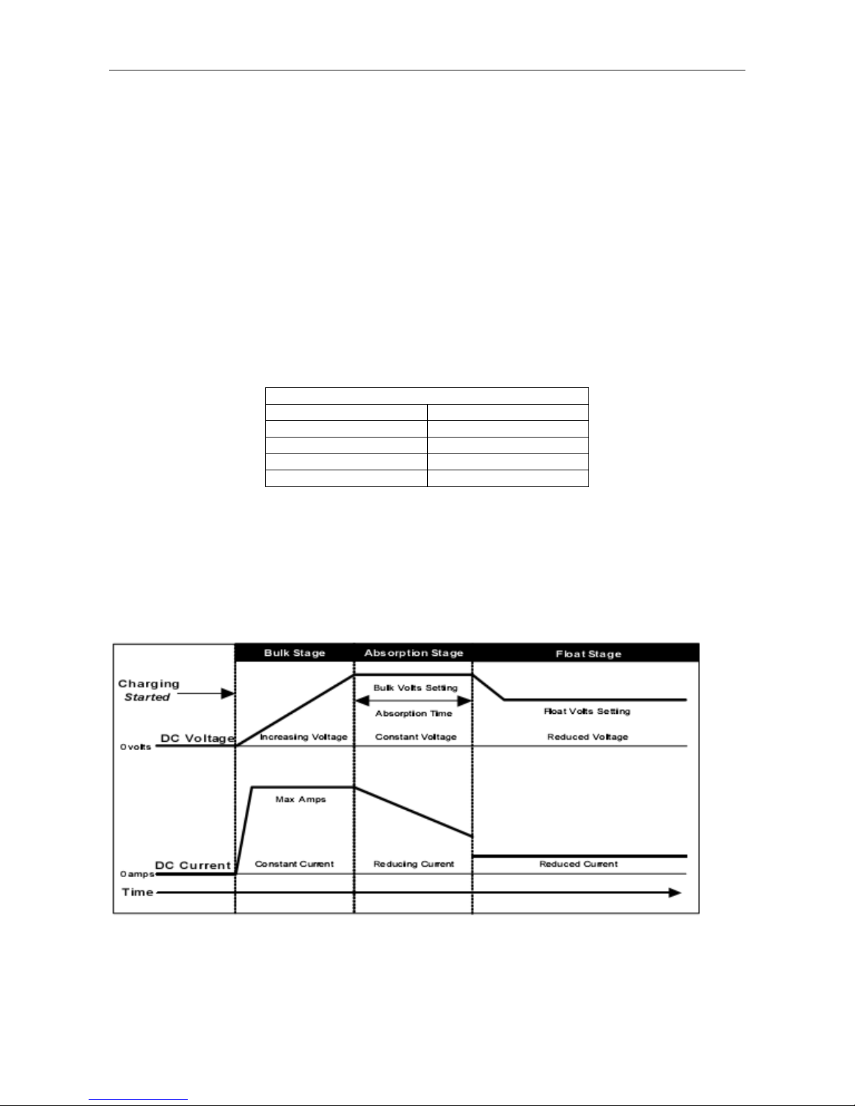
11..1100 TThhrreeee ssttaaggee cchhaarrggee ccoonnttrrooll
Solar charger controller is typically configured for a three stage charging process, Bulk, Absorption and Float. The
three stage charge process provides a somewhat higher charge voltage to charge the battery quickly and safely.
Once the battery is fully charged a somewhat lower voltage is applied maintain the battery in a fully charged state
without excessive water loss. The three stage charge process charges the battery as quickly as possible while
minimizing battery water loss and maintenance.
Figure 1 – 1: Bulk charge curve
1.10.1 Bulk charge
When charge starts the Solar charger controller attempts to apply the bulk charge voltage to the battery. The
system will switch to Bulk charge if the battery is sufficiently discharged and/or insufficient charge current is
available to drive the battery up to the bulk voltage setpoint. During the Bulk charge stage the unit delivers as
much charge current as possible to rapidly recharge the battery. Once the charge control system enters Absorption
or Float, the unit will again switch to Bulk charge if battery voltage drops below the present charge voltage
 Loading...