

Sigineer Power Power Star W7 User Manual
Power Star W7 Pure Sine Wave Inverter/Charger User’s Manual www.sigineer.com
1
Power Star W7 Inverter/Charger
600W&1000W
Pure Sine Wave
User’s Manual
Shenzhen Sigineer Power CO.,LTD.
Email: info@sigineer.com
TEL: +86 755 2160 7078
FAX: +86 755 6165 8278
Add: Bld A, Jiali Industrial Zone, Yuanfen Rd, Longhua, Shenzhen, 518100, China

Power Star W7 Pure Sine Wave Inverter/Charger User’s Manual www.sigineer.com
2
Table of Contents
1 Important Safety Information ..................................................................................................................... 3
1.1 General Safety Precautions ..................................................................................................................... 3
1.2 Precautions When Working with Batteries .............................................................................................. 4
2 Introduction ............................................................................................................................................... 4
2.1 General Information ................................................................................................................................ 4
2.4 Features ................................................................ ................................................................................. 5
2.5 Electrical Performance .......................................................................................................................... 5
2.5.1 Invert ............................................................................................................................................ 5
2.5.2 AC Charger ................................................................................................................................... 6
2.5.3 Transfer ......................................................................................................................................... 8
2.5.4 Remote Operation ......................................................................................................................... 8
2.5.5 Protections .................................................................................................................................... 9
2.5.7 LED Indicator ............................................................................................................................... 9
2.5.8 Audible Alarm ............................................................................................................................. 10
2.5.9 FAN Operation ............................................................................................................................ 10
2.5.10 DIP Switches ............................................................................................................................. 11
2.5.11 Auto Generator Start(Optional) .................................................................................................. 13
2.5.12 Battery Temperature Sensing(Optional) ..................................................................................... 13
2.5.13 Other Features ........................................................................................................................... 13
3 Installation ............................................................................................................................................... 15
3.1 Location ......................................................................................................................................... 15
3.2 DC Wiring Recommendation ......................................................................................................... 15
3.3 AC Wiring Recommendations ........................................................................................................ 16
3.4 Grounding ...................................................................................................................................... 17
3.5 Mounting Flange ............................................................................................................................ 17
4 Maintenance & Troubleshooting .............................................................................................................. 19
5 Warranty .................................................................................................................................................. 21
Appendix 1 : PSW7 Series Inverter/Charger Spec Sheet ............................................................................. 21

Power Star W7 Pure Sine Wave Inverter/Charger User’s Manual www.sigineer.com
3
1 Important Safety Information
Save This Manual! Read this manual before installation, it contains important safety, installation
and operating instructions. Keep it in a safe place for future reference.
All wiring must follow the National Electric Code, Provincial or other codes in effect at the time
of installation, regardless of suggestions in this manual. All wires should be copper conductors.
1.1 General Safety Precautions
1.1.1 Before installing and using the PSW7 Series Pure Sine Wave Inverter/Charger, read the manual and
cautionary markings on the Inverter/Charger enclosure. Be sure to read all instructions and cautionary
markings for any equipment attached to this unit. Installers must be certified technicians or electricians.
1.1.2 This product is designed for indoor/compartment installation. Do not expose the inverter/charger to
rain, snow, spray, bilge or dust. To reduce risk of hazard, do not cover or obstruct the ventilation openings.
Do not install the inverter/charger in a zero-clearance compartment. Overheating may result. Allow at least
one inch of clearance around the inverter for air flow. Make sure that the air can circulate freely around the
unit. A minimum air flow of 145CFM is required.
1.1.3 To avoid a risk of fire and electronic shock. Make sure that existing wiring is in good electrical
condition; and that wire size is not undersized. Do not operate the Inverter with damaged or substandard
wiring.
1.1.4 This equipment contains components which can produce arcs or sparks. To prevent fire or explosion
do not install in compartments containing batteries or flammable materials or in locations which require
ignition protected equipment. This includes any space containing gasoline-powered machinery, fuel tanks,
or joints, fittings, or other connection between components of the fuel system. See Warranty for instructions
on obtaining service.
1.1.5 Do not dis-assemble the Inverter/Charger. It contains no user serviceable parts. Attempting to service
the Inverter/Charger yourself may result in a risk of electrical shock or fire. Internal capacitors remain
charged after all power is disconnected.
1.1.6 To reduce the risk of electrical shock, disconnect both AC and DC power from the Inverter/Charger
before attempting any maintenance or cleaning. Turning off controls will not reduce this risk
CAUTION: Equipment damage
The output side of the inverter’s AC wiring should at no time be connected to public power or a generator.
This condition is far worse than a short circuit. If the unit survives this condition, it will shut down until
corrections are made.
Installation should ensure that the inverter’s AC output is, at no time, connected to its AC input.
WARNING: LIMITATIONS ON USE
SPECIFICALLY, PLEASE NOTE THAT THE INVERTER/CHARGER SHOULD NOT BE USED IN
CONNECTION WITH LIFE SUPPORT SYSTEMS OR OTHER MEDICAL EQUIPMENT OR DEVICES.
WE MAKE NO WARRANTY OR REPRESENTATION IN CONNECTION WITH THEIR PRODUCTS
FOR SUCH USES. USING THE INVERTER/CHARGER WITH THESE PARTICULAR EQUIPMENTS
IS AT YOUR OWN RISK.

Power Star W7 Pure Sine Wave Inverter/Charger User’s Manual www.sigineer.com
4
1.2 Precautions When Working with Batteries
1.2.1 If battery acid contacts skin or clothing, wash immediately with soap and water. If acid enters eye,
immediately flood eye with running cold water for at least 20 minutes and get medical attention
immediately.
1.2.2 Never smoke or allow a spark or flame in vicinity of battery or engine.
1.2.3 Do not drop a metal tool on the battery. The resulting spark or short-circuit on the battery of other
electrical part may cause an explosion.
1.2.4. Remove personal metal items such as rings, bracelets, necklaces, and watches when working with a
lead-acid battery. A lead-acid battery produces a short-circuit current high enough to weld a ring or the like
to metal, causing a severe burn.
1.2.5 To reduce the risk of injury, charge only rechargeable batteries such as deep-cycle lead acid, lead
antimony, lead calcium gel cell, absorbed mat, and NiCad/NiFe or Lithium battery. Other types of batteries
may burst, causing personal injury and damage.
2 Introduction
2.1 General Information
Thank you for purchasing the PSW7 Series Pure Sine Wave Inverter/Charger.
The PSW7 Series Pure Sine Wave Inverter/Charger is a transformer based inverter and battery charger with
an unprecedented conversion efficiency of 90%.
This lines has two popular models: the 600 watt inverter, 1000 watt invertr.
It features power factor corrected, sophisticated multi-stage charging control and pure sine wave output with
high surge capability to meet power needs of all sorts of demanding loads without putting the equipment at
risk.
In response to the increasing demand of more advanced battery charging, our engineering team equipped the
inverter with a Battery Temperature Sensing probe for increased charging precision.
The generous 300% surge capacity of 20 seconds makes it possible to support demanding inductive loads.
The AC/Battery priority, auto generator start functionality and optional built-in charger make it ideally
suitable to work in backup power or anti-idle applications.
When customized to Battery priority mode via a DIP switch, the Power Star W7 inverter will extract
maximum power from external power sources and a minimal cycle of battery will be required. With the
availability of auto generator start, an electrical generator can be integrated into the system and started when
the battery voltage goes low.
With audible buzzer and remote LCD panel, the inverter gives the users comprehensive information of the
operation status, making it easier for maintenance and troubleshooting.
Thus the PSW7 Series Pure Sine Wave Inverter/Charger is suitable for applications including renewable
energy systems, utility, truck, RV and emergency vehicles etc.
To get the most out of the power inverter, it must be installed, used and maintained properly. Please read the
instructions in this manual before installing and operating.
Power Star W7 Pure Sine Wave Inverter/Charger User’s Manual www.sigineer.com
5
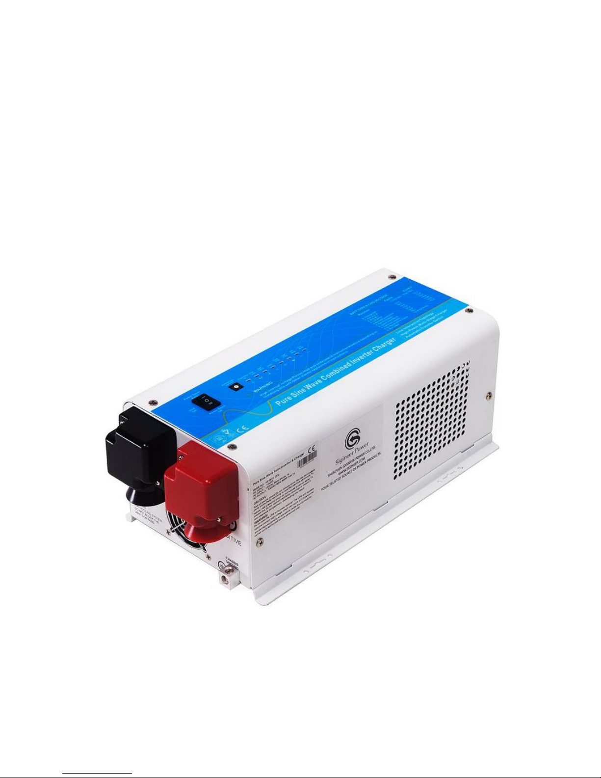
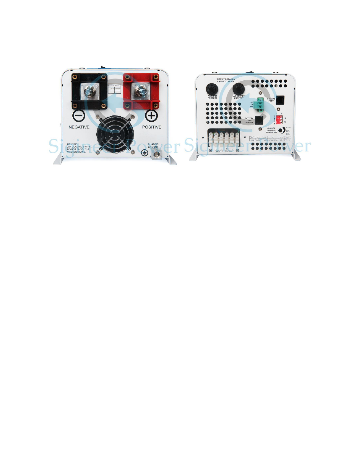
2.3 Mechanical Drawing
2.4 Features
Smart remote LCD control
Auto Generator Start(Optional)
Battery Temperature Sensing for increased charging precision(Optional)
Manual 50Hz/60Hz output frequency switch
Maximum 90% conversion efficiency
High surge output capability, 300% peak load for 20 seconds
Low quiescent current
Battery type selector for 8 types of batteries and de-sulphation for completely drained batteries
10ms transfer time from AC to battery for continuous load operation
15 sec DC to AC transfer delay, improved protection for generator driven loads
Thermally controlled variable speed fan for more efficient cooling
Extensive protections against various harsh situations
2.5 Electrical Performance
2.5.1 Invert
Topology
The PSW7 Series pure sine wave inverter/charger is built according to the following topology.
Invert: Full Bridge Topology.
Charge: Isolated Boost Topology
When operating in invert mode, the direct current (DC) that enters the inverter from the batteries is filtered

Power Star W7 Pure Sine Wave Inverter/Charger User’s Manual www.sigineer.com
6
by a large input capacitor and switched “On” and “Off” by the Metal Oxide Silicon Field Effect Transistors
(MOSFET) at a rate of 50 Hz or 60Hz, and directed into the transformer which steps the voltage up to 230 or
120 volts. The unit has a 16bit, 4.9MHZ microprocessor to control the output voltage and frequency as the
DC input voltage and/or output load varies.
Because of high efficiency MOSFETs and the heavy transformers, it outputs PURE SINE WAVE AC.
The peak invert efficiency of PSW7 Series is 90%.
Overload Capacity
The Power Star inverter charger has different
overload capacities, making it ideal to handle
demanding loads.
1 For 110%<Load<125% (±10%), no audible alarm
in 14 minutes, beeps 0.5s every 1s in the 15th minute,
and Fault (Turn off) after the 15th minute.
2 For 125%< Load<150% (±10%), beeps 0.5s every 1s and Fault (Turn off) after the 1 minute.
3 For 300%≧Load>150% (±10%), beeps 0.5s every 1s and Fault (Turn off) after 20s.
Caution:
After the inverter is switched on, it takes 3-5 seconds for it to self diagnose and get ready to deliver full
power. Hence, always switch on the load(s) after a few seconds of switching on the inverter. Avoid
switching on the inverter with the load already switched on. This may prematurely trigger the overload
protection. When a load is switched on, it may require initial higher power surge to start. Hence, if multiple
loads are being powered, they should be switched on one by one so that the inverter is not overloaded by the
higher starting surge if all the loads are switched on at once.
2.5.2 AC Charger
The PSW7 Series pure sine wave inverter/charger is equipped with an active PFC (Power Factor Corrected)
multistage battery charger. The PFC feature is used to control the amount of power used to charge the
batteries in order to obtain a power factor as close as possible to 1.
Unlike other inverters whose max charging current decreases according to the input AC voltage, PSW7
Series pure sine wave inverter/charger is able to output max charge current as long as input AC voltage is in
the range of 164-243VAC(95-127VAC for 120V model), and AC freq is in the range of 48-54Hz(58-64Hz
for 60Hz model).
The PSW7 Series pure sine wave inverter/charger has a very rapid charge current available, and the max
charge current can be adjusted from 0%-100% via a liner switch on the DC side of the inverter. This will be
helpful if this powerful charger apply charging on a small capacity battery bank.
Choosing “0” in the battery type selector will disable charging function.
There are three main charging stages:
Bulk Charging: This is the initial stage of charging. While Bulk Charging, the charger supplies the battery
with controlled constant current. The charger will remain in Bulk charge until the Absorption charge voltage
(determined by the Battery Type selection) is achieved.
Software timer will measure the time from charger start until the battery charger reaches 0.3V below the
boost voltage, then take this time as T0 and T0×10 = T1.
Battery type selector
Switch
setting
Description
Boost /
Vdc
Float /
Vdc
0
Charger Off

Power Star W7 Pure Sine Wave Inverter/Charger User’s Manual www.sigineer.com
7
Absorb Charging: This is the second charging stage
and begins after the absorb voltage has been reached.
Absorb Charging provides the batteries with a
constant voltage and reduces the DC charging current
in order to maintain the absorb voltage setting.
In this period, the inverter will start a T1 timer; the
charger will keep the boost voltage in Boost CV
mode until the T1 timer has run out. Then drop the
voltage down to the float voltage. The timer has a
minimum time of 1 hour and a maximum time of 12
hours.
Float Charging: The third charging stage occurs at the end of the Absorb Charging time. While Float
charging, the charge voltage is reduced to the float charge voltage (determined by the Battery Type
selection*). In this stage, the batteries are kept fully charged and ready if needed by the inverter.
If the A/C is reconnected or the battery voltage drops below 12Vdc/24Vdc/48Vdc, the charger will reset the
cycle above.
If the charge maintains the float state for 10 days, the charger will deliberately reset the cycle to protect the
battery.
De-sulphation
The de-sulphation cycle on switch position 8 is marked in red because this is a very dangerous setting if you
do not know what you are doing. Before ever attempting to use this cycle you must clearly understand what
it does and when and how you would use it.
What causes sulphation? This occurs with infrequent use of the batteries, nor if the batteries have been left
discharged so low that they will not accept a charge. This cycle is a very high voltage charge cycle
especially designed to try to break down the sulphated crust that is preventing the plates from taking a
charge and thus allow the plates to clean up and accept a charge once again.
Warning!
1
Gel USA
14.0
13.7
2
AGM 1
14.1
13.4
3
Lithium Ion (LiFeP04)
14.6
13.7
4
Sealed lead acid
14.4
13.6
5
Gel EURO
14.4
13.8
6
Open lead acid
14.8
13.3
7
Calcium
15.1
13.6
8
De sulphation
15.5 (4 Hours
then Off)
9
Not used
 Loading...