

Page 1

SNT 1.1
GEN-PMT-GUI03-SNT_user_guide_quick
User Guide
February 2017
Page 2

Revision history:
Rev. Date Author Change description
0.1 08/02/2017 A. Trombetta Preliminary version
0.2 13/02/17 A. Trombetta Tables of command and LED
0.3 16/02/2017 A. Trombetta SNT photo
0.4 20/02/17 A. Trombetta Added command to table
0.5 22/02/17 A. Trombetta Clarify display type in backend
1.0 16/05/17 A. Trombetta SNT 1.1
2
Page 3

Contents
I. INTRODUCTION ....................................................................................................................................... 4
II. REQUIREMENTS ...................................................................................................................................... 5
1. R
ADIO CONSIDERATIONS
2. C
ABLE CONNECTION
3. S
OFTWARE REQUIREMENTS
4. R
EGISTRATION IN THE BACKEND
III. SNT OPERATIONAL MODES ..................................................................................................................... 6
1. S
TANDALONE
A. Uplink sequence ................................................................................................................................... 7
B. Bidirectional sequence ......................................................................................................................... 7
C. Uplink frame format ............................................................................................................................. 8
2. S
ERIAL AT COMMANDS OPERATION
3. LED
IV. WARNING STATEMENTS ........................................................................................................................ 10
1. FCC: ......................................................................................................................................................... 10
2. IC ............................................................................................................................................................. 10
3. CE ............................................................................................................................................................ 11
................................................................................................................................................ 6
RECAPITULATIVE TABLE
.................................................................................................................................. 5
....................................................................................................................................... 5
.............................................................................................................................. 5
........................................................................................................................ 6
................................................................................................................... 8
............................................................................................................................. 9
3
Page 4
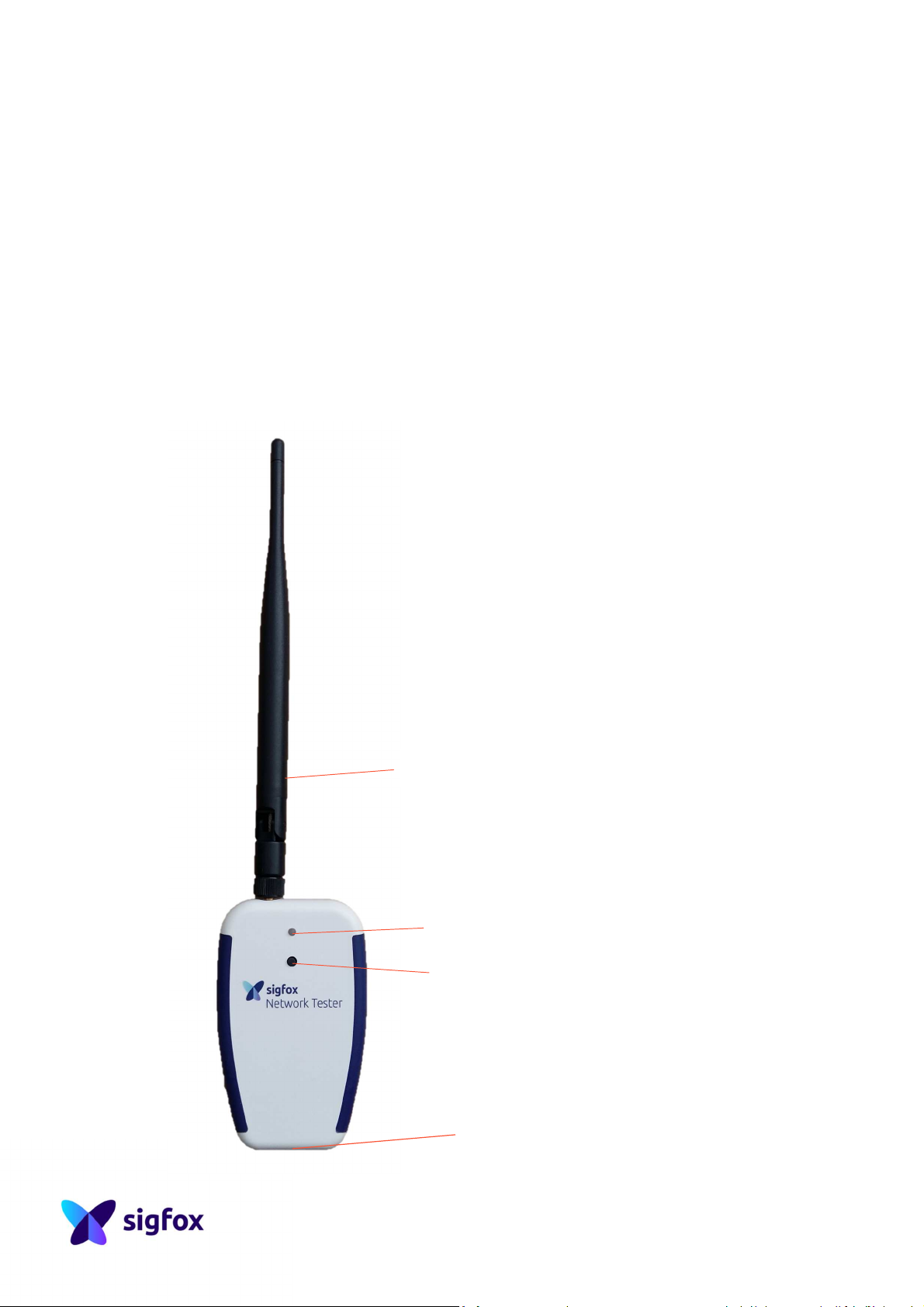
I. Introduction
Sigfox Network Tester (SNT), is a Sigfox device provided exclusively for
technology evaluation and network coverage reference measurements.
Its primary functionality consists in periodic transmission of Sigfox radio messages
meant for reception at any Sigfox Access Points. Each SNT has a unique network
identity, printed on a sticker at the back and stored into its memory. With this ID, full
retrieval of the device activity is possible through the OSS portal.
SNT 1.1 is available in 4 versions to cover worldwide RF requirements:
SNT1.1-1, SNT1.1-2, SNT1.1-3, SNT1.1-4
Antenna
LED
ON/OFF button
Micro USB port
4
Page 5

II. Requirements
1. Radio considerations
SNT serves as reference device. It is equipped with a 1⁄2 wave antenna. For reference
performance level, classical radio precautions have to be observed during operation:
antenna vicinity has to be cleared of any metallic object, and antenna shall be kept in
vertical position.
Note that Sigfox Network optimal performance is obtained in stationary operation.
2. Cable connection
SNT comes with a micro USB to USB cable.
SNT is equipped with a rechargeable battery. When the device is connected to a USB
charger or a USB socket of a computer, it will start to charge automatically (blue
LED). The device can be used while charging.
The battery takes about 3 hours to fully charge.
SNT can be used and controlled by computer using the same USB cable. In this case,
check the Software requirements (below).
3. Software requirements
SNT is controlled by AT commands and works with Windows, Linux and Mac. Just
make sure you to have:
• FTDI drivers installed on your computer
• Any soft to open serial port like Putty for Windows, Screen or Cutecom on
Linux
See SNT drivers installation guide for detailed information.
5
Page 6

4. Registration in the Backend
Each device needs to be registered in the OSS Portal (Backend interface).
In Device type configuration, you can configure the display type.
Depending on how you will use your SNT, you can configure it like this:
• To have GPS location displayed in the Backend, select in Type: Geolocation
and Default [Root] :
• To get information about battery and frame counter, select Type : Custom
and Custom configuration with :
Vdd::uint:16 NA::uint:16 NA1::uint:16 NA2::uint:16 CounterDL::uint:16
CounterUL::uint:16
III. SNT operational modes
SNT has two operational modes: standalone and serial communication.
The device shall be used hand-held in upright position only. Alternatively the device
may be used when put on the desk or an supporting structure.
The device is not designed and must not be used nearby body like belt-worn, lanyard
around the neck or put into pocket.
1. Standalone
Pressing the button for a few seconds will activate the device. The LED lights blue as
the device turns on. Then the device will execute the sequences described below.
SNT has two main options: monodirectional (uplink only) and bidirectional sequences
(uplink and downlink).
By default, SNT is set to Uplink mode. These modes can be set by AT commands
(see next chapter).
These sequences are looped 10 times, then device shuts down automatically.
6
Page 7

A. Uplink sequence
Just after powering up, SNT sends a SIGFOX message every 10 minutes by default.
This option can be set by AT commands. This message contains GPS information if
available.
When SNT is sending, green led is blinking.
Between two messages, SNT led can be of one of these two colours:
• Green if internal GPS is fixed
• Orange if it is not the case
B. Bidirectional sequence
In this mode the device is sending and receiving frames. The LED colour is pink.
The sequence is:
1. TX : device sending an uplink message.
2. IDLE: device in wait state (20 seconds)
3. RX: device in receive mode (timeout after 25 seconds)
Depending on the reception result, there are two possible cases:
> case 1: sequence completion by successful downlink frame reception
4. Led blinking in green, indicating successful message reception and send an
OOB message
5. Link quality indication is displayed for 10sec (details below)
Or
> case 2: sequence completion timeout after 25 secs (NO frame received)
4. LEDs blinking in RED 3 times (~6seconds)
Link quality indication:
Providing the Backend direct callback is used and includes uplink RSSI, the link quality
is flashed using a LED code:
• LINK QUALITY = VERY GOOD → Blinks 3 times (WHITE)
• LINK QUALITY = GOOD → Blinks 2 times (WHITE)
• LINK QUALITY = AVERAGE → Blinks 1 time (WHITE)
Note: The white LED may appear slightly pink.
7
Page 8

C. Uplink frame format
SIGFOX payload is composed of 12 bytes. The format of payload is available in the
following table.
Note: Vdd in mV
2. Serial AT commands operation
AT commands can be sent to the device by connecting the USB cable to a computer
and opening a serial interface.
All the basics available commands are listed here:
Commands Responses Descriptions and comments
AT OK
AT?
AT&V <device info>
AT$SF=<value>,<ack
>
AT$NC=<value> OK
AT$NC? Current value 10
AT$BI=<value> OK Enable (1) or disable (0) bidirectional mode 0
AT$BI? Current value 0
AT$ID=<value> OK
AT$ID? Current value 600
AT$GPS=<value> OK
AT$GPS ? Current value 1
AT$FSD=<value> OK
AT$FSD ? Current value 2
AT$OT=<value> OK
AT$OT? Current value 0
AT$FP=<value> OK
<cmdlist>
OK
OK
Attention command. Just to be sure that all
works fine!
Requests summary of available AT commands
Display device version information (SNT type,
SW version, ID, PAC)
Send a Sigfox Frame. Value must be in hex
format by byte (ex : AABB74)
Change number cycle before shutdown.
Value > 0. Or 0 for infinite
Change inter-message delay in seconds.
0 < Value < 65536
Enable (1) or disable (0) GPS.
Value 0 improve SNT battery life
Set Delay before first message (in second)
0 < Value < 65536
Enable (1) or disable (0) OneTouch mode
(describe bellow)
Enable (1) or disable (0) Factory reset. You
need restart after with “ATR\r” command
Default
values
10
600
1
2
0
8
Page 9

Blue
Green
orange
green
Green
pink
Green
Red
pink
Red
blue
AT$FP? Current value
ATR Soft reset
AT$OT for OneTouch
When this command is at 1, the SNT send only one Sigfox message instantly after
having pushed the button.
This frame is: “HELLO WORLD!” in ASCII.
3. LED recapitulative table
Here is a recapitulative of the lights’ sequences and their meanings:
Mode LED colour Meaning
On
Device turning on
Uplink mode
sequence
Bidirectional mode
sequence
Off
Connected
Flashing
Flashing
blinking x3
Flashing
Flashing x1
flashing x3
flashing x2
flashing x1
flashing x3
Slow flashing
Fixed
Sending 3 frames
Searching GPS
GPS found
Sending 3 frames
Waiting for Backend response
Successful msg reception + send
OOB msg
Very good link quality
Good link quality
Limit link quality
Failed to receive frame
Idle time before new cycle
Device turning off
Device charging or charged
9
Page 10

IV. WARNING STATEMENTS
1. FCC:
This device complies with Part 15 of the FCC Rules.
• Operation is subject to the following two conditions:
(1) This device may not cause harmful interference, and
(2) This device must accept any interference received, including interference that
may cause undesired operation.
• The radiated output power of the device is far below the FCC radio frequency
exposure limits. Nevertheless, the device shall be used in such a manner that
the potential for human contact during normal operation is minimized.
• Changes or modifications not expressly approved by the party responsible for
compliance could void the user's authority to operate the equipment
NOTE: This equipment has been tested and found to comply with the limits for a
Class B digital device, pursuant to Part 15 of the FCC Rules. These limits are designed
to provide reasonable protection against harmful interference in a residential
installation. This equipment generates, uses and can radiate radio frequency energy
and, if not installed and used in accordance with the instructions, may cause harmful
interference to radio communications. However, there is no guarantee that
interference will not occur in a particular installation. If this equipment does cause
harmful interference to radio or television reception, which can be determined by
turning the equipment off and on, the user is encouraged to try to correct the
interference by one or more of the following measures:
• Reorient or relocate the receiving antenna.
• Increase the separation between the equipment and receiver.
• Connect the equipment into an outlet on a circuit different from that to which
the receiver is connected.
• Consult the dealer or an experienced radio/TV technician for help.
2. IC
English
This device complies with Part 15 of the FCC Rules and with Industry Canada licenseexempt RSS standard(s).
Operation is subject to the following two conditions:
this device may not cause harmful interference, and
this device must accept any interference received, including interference that may
cause undesired operation.
Français
Le présent appareil est conforme aux CNR d'Industrie Canada applicables aux
10
Page 11

appareils radio exempts de licence. L'exploitation est autorisée aux deux conditions
sigfox
suivantes :
(1) l'appareil ne doit pas produire de brouillage, et
(2) l'utilisateur de l'appareil doit accepter tout brouillage radioélectrique subi, même
si le brouillage est susceptible d'en compromettre le fonctionnement.
3. CE
Do not throw away in the normal household waste. The device must be disposed of
in the same way as other electronic equipment following local procedures.
4. Japan
Japanese Radio Law and Japanese Telecommunications Business Law Compliance.
This device is granted pursuant to the Japanese Radio Law (電波法) .
This device should not be modified (otherwise the granted designation number will
become invalid).
425 rue Jean Rostand, 31670 Labège, France www.sigfox.com
The information presented is subject to change without notice. Sigfox assumes no responsibility for inaccuracies contained herein.
Sigfox and the sigfox logo are trademarks of Sigfox. All other trademarks are the property of their respective owners.
Copyright ©2017 sigfox. All right reserved
11
 Loading...