

Page 1

Installation guide
SBS-T-902
Ref.: MAN/DPL/EN/001
Rev.: 2.3
Date: 29 August 2014
Installation Guide
NOTICE: This document and its content are the property of SIGFOX. They are confidential and shall not be disclosed,
disseminated, copied, or used except for purposes expressly authorized in writing by SIGFOX
© Copyright SIGFOX. All rights reserved
Page 1 of 21
Page 2

installation Guide
Ref.: MAN/DPL/EN/001
Rev.: 2.3
Date: 29 August 2014
Table of contents
1 Specifications ............................................................................................................................... 4
2
Warning statements ..................................................................................................................... 5
2.1 FCC warning statement .......................................................................................................................5
2.2 IC warning statement ..........................................................................................................................5
3
Installation synoptic ..................................................................................................................... 6
3.1 Redundant AC main power supply from site (power switch time < 10 ms) .....................................6
3.2 Redundant power supply from inverter SIGFOX approved model : .................................................7
4
Bill of material .............................................................................................................................. 8
5
Antenna installation ................................................................................................................... 10
5.1 Warning statement relative to radiofrequency exposure: ..............................................................10
5.2 Installation: ........................................................................................................................................10
5.3 Recommendations: ...........................................................................................................................11
6
LNA Installation .......................................................................................................................... 12
7
Waterproofness .......................................................................................................................... 12
8
Earthing of coaxial cable and routing ....................................................................................... 13
9
Feeders measurement ................................................................................................................ 15
10
Coaxial Bending Radius ........................................................................................................... 16
11
Key risks ................................................................................................................................... 16
12
Base Station Installation ......................................................................................................... 17
13
Electrical connection ............................................................................................................... 20
14
Labeling ................................................................................................................................... 20
14.1 Installation: ....................................................................................................................................20
14.2 Identification number: ..................................................................................................................20
15
Connectivity ............................................................................................................................. 21
15.1 Via ADSL (primary).........................................................................................................................21
15.2 Via Satellite connection (primary) ................................................................................................21
15.3 Via the 3G network (secondary) ...................................................................................................21
16
Base station « switching on » procedure ............................................................................... 21
© Copyright SIGFOX. All rights reserved Page 2 of 21
Page 3
installation Guide
Ref.: MAN/DPL/EN/001
Rev.: 2.3
Date: 29 August 2014
Changes description
Version Description Author Date
1.0 Creation F.AUBINEAU 07 Oct 2013
2.0 Additional information (product specifications, electrical
connection)
2.1 Additional FCC and IC Warning statements P.ANTOINE 28 July 2014
2.2 Modification of specifications P.ANTOINE 04 Aug 2014
2.3 Additional Warning statement relative to radiofrequency
exposure (paragraph 5.1)
P.ANTOINE 03 Dec 2013
P.ANTOINE 29 Aug 2014
Acronyms
Acronym Description
ETH Ethernet
LNA Low Noise Amplifier
PVC Polyvinyl Chloride
RF Radio Frequency
SAT Satellite
TAP Transfox Access Point
VSWR Voltage Standing Wave Ratio
UNB Ultra Narrow Band
EIRP Equivalent isotropically radiated power
© Copyright SIGFOX. All rights reserved Page 3 of 21
Page 4
installation Guide
1 Specifications
Radio Interface characteristics
Standard SIGFOX UNB Protocol
Frequency range 902 to 928 MHz
Monitored spectrum 192kHz
Radio Mode Access Point
Receiver Sensitivity -134dBm @600bps
Transmit Power Max 4W (+36 dBm) EIRP
Data Rate and Modulation 600bps D-BPSK
Ref.: MAN/DPL/EN/001
Rev.: 2.3
Date: 29 August 2014
Antenna Connector Type N Female
INTERFACES
Ethernet 1x10/100BaseT (RJ45)
USB 2xUSB2.0 ports (optional for 3G key and/or external inverter)
Maintenance port RJ45 socket with specific cable (only for maintenance)
POWER SUPPLY
Power Consumption 40W typical, 70W max peak (in transmit mode)
Power supply 100-240VAC 50Hz-60Hz -- 12 VDC / 7A max
MECHANICAL & ENVIRONMENTAL
Product dimensions 480 x 350 x 85 mm (19’’ 2U standard format)
Product weight Ca 8kg (16 lbs)
Operating temperature -20 to +50°C
Storage temperature -40°C to +85°C
Maximum altitude operation 2000 m
Pollution degree 2
Overvoltage category II
Casing material Aluminum and steel
COMPLIANCE
compliance CE (EMC EN 301 489, radio EN 300 220, safety EN60950-1)
© Copyright SIGFOX. All rights reserved Page 4 of 21
Page 5

2 Warning statements
2.1 FCC warning statement
• This device complies with Part 15 of the FCC Rules.
Operation is subject to the following two conditions:
(1) This device may not cause harmful interference, and
(2) This device must accept any interference received, including interference that may cause
undesired operation.
• This equipment complies with FCC radiation exposure limits set forth for an uncontrolled
environment. End users must follow the specific operating instructions for satisfying RF exposure
compliance. This transmitter must not be co-located or operating in conjunction with any other
antenna or transmitter.
• Changes or modifications not expressly approved by the party responsible for compliance could
void the user's authority to operate the equipment
2.2 IC warning statement
installation Guide
Ref.: MAN/DPL/EN/001
Rev.: 2.3
Date: 29 August 2014
English
French
"Under Industry Canada regulations, this radio transmitter may only operate using an antenna of a
type and maximum (or lesser) gain approved for the transmitter by Industry Canada.
To reduce potential radio interference to other users, the antenna type and its gain should be so
chosen that the equivalent isotropically radiated power (e.i.r.p.) is not more than that necessary
for successful communication."
"This device complies with Industry Canada licence-exempt RSS standard(s). Operation is subject to
the following two conditions: (1) this device may not cause interference, and (2) this device must
accept any interference, including interference that may cause undesired operation of the device."
"Conformément à la réglementation d'Industrie Canada, le présent émetteur radio peut
fonctionner avec une antenne d'un type et d'un gain maximal (ou inférieur) approuvé pour
l'émetteur par Industrie Canada.
Dans le but de réduire les risques de brouillage radioélectrique à l'intention des autres utilisateurs,
il faut choisir le type d'antenne et son gain de sorte que la puissance isotrope rayonnée
équivalente (p.i.r.e.) ne dépasse pas l'intensité nécessaire à l'établissement d'une communication
satisfaisante."
"Le présent appareil est conforme aux CNR d'Industrie Canada applicables aux appareils radio
exempts de licence. L'exploitation est autorisée aux deux conditions suivantes : (1) l'appareil ne
doit pas produire de brouillage, et (2) l'utilisateur de l'appareil doit accepter tout brouillage
radioélectrique subi, même si le brouillage est susceptible d'en compromettre le fonctionnement."
© Copyright SIGFOX. All rights reserved Page 5 of 21
Page 6
installation Guide
Ref.: MAN/DPL/EN/001
Rev.: 2.3
Date: 29 August 2014
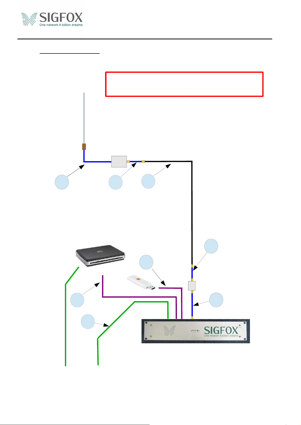
3 Installation synoptic
3.1 Redundant AC main power supply from site (power switch time < 10 ms)
Redundant power supply is mandatory
Case 1 : redundant AC main power supply from site.
Antenna
1
11
Connectivity
●
ADSL
●
SAT
●
Other
3
LNA
7
USB 3G Key
5
5
2
58
Surge
Surpressor
58
Option
11-1
Example of a base station
Redundant AC main
power supply from
site
© Copyright SIGFOX. All rights reserved Page 6 of 21
Page 7
installation Guide
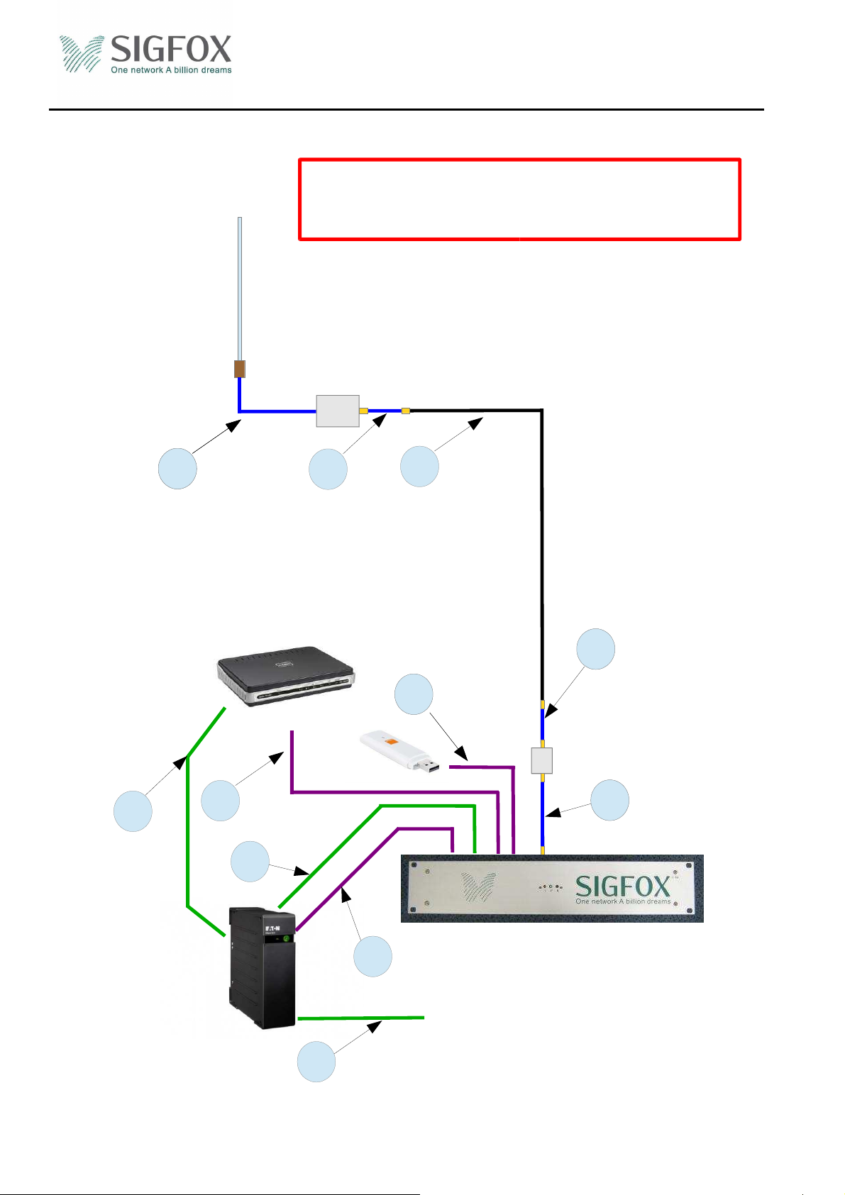
3.2 Redundant power supply from inverter SIGFOX approved model :
Redundant power supply is mandatory
Case 2 : redundant power supply from inverter
SIGFOX approved model.
Antenna
LNA
Ref.: MAN/DPL/EN/001
Rev.: 2.3
Date: 29 August 2014
1
11
Connectivity
●
ADSL
●
SAT
●
Other
10
3
11-2
7
USB 3G Key
5
5
2
58
Surge
Surpressor
58
Option
Example of a base station
13
AC main Power
Inverter
SIGFOX approved model
supply
12
© Copyright SIGFOX. All rights reserved Page 7 of 21
Page 8

installation Guide
Ref.: MAN/DPL/EN/001
Rev.: 2.3
Date: 29 August 2014
4 Bill of material
• Antenna and feeder
Component Description Index Supplier Quantity
Antenna
Antenna mounting support
Low Noise Amplifier
LNA V2 mounting plate
Omnidirectional antenna
2.1m high max
Steel bracket between existing
support and antenna.
SIGFOX Preamp 868
- SIGFOX 1
- DISTRIBUTOR 1
- SIGFOX 1
- SIGFOX 1
1/2" or 7/8’’ coaxial cable
2 DISTRIBUTOR
Depends on
site
configuratio
n
Jumper cable LMR400 : Ant <->
Feeder cable
LNA (L=1.5m) connector
Nmale/Nmale
Jumper cable LMR400 : LNA <->
feeder 1/2" (L=1.5m max)
1 DISTRIBUTOR 1 Depends on
the Antenna
7 DISTRIBUTOR 1
connector Nmale/Nfemale
Jumper cable LMR 400 : 1/2" <->
TAP (L=1.5m max) connector
8 DISTRIBUTOR 1 or 2
Nmale/Nfemale
Connector
Surge suppressor
Grounding kit for 1/2"
feeder
Nmale feeder
connector
Telegartner 90V J01028A0034
- DISTRIBUTOR 2
- DISTRIBUTOR 1
DISTRIBUTOR 2
• Power supply – Case 1 : Redundant AC main power supply from site
Component Description
Base station Power cable
220V power cable IEC (plug to
fem) to TAP
Index
Supplier Quantity
11-1 SIGFOX 1
• Power supply – Case 2 - Redundant power supply from inverter SIGFOX approved model
Component Description
Index
Supplier Quantity
220V Inverter SIGFOX approved
Inverter (option if power
supply is not redundant)
model : INFOSEC X3 500 USB
ONDULEUR 500VA & EATON 5 S
- DISTRIBUTOR 1
550
Control cable Inverter
(option if power supply is
USB Cable type A to type B (1 ml)
13 DISTRIBUTOR 1
not redundant)
Power cable Inverter (option
if power supply is not
220V power cable IEC (plug to
fem) to Inverter 12 SIGFOX 1
redundant)
Base station Power cable
© Copyright SIGFOX. All rights reserved Page 8 of 21
220V power cable IEC (male to
11-2 DISTRIBUTOR 1
Page 9

installation Guide
(UPS to TAP) fem)
SAT Modem Power cable
X DSL Modem Power cable
• Base station
Component Description
TAP
• Internet connexion
Component Description
Modem
Ethernet cable
USB 3G key
220V power cable IEC (male to
fem)
220V power cable IEC (Plug to
fem)
Tap-868 V2
ADSL modem + power cable
Cable RJ45 1m
3G key SIGFOX approved model :
Huawei E352/K3806
Standard M2M SIM card
without PIN code neither password
USB cable – 50cm
Ref.: MAN/DPL/EN/001
Rev.: 2.3
Date: 29 August 2014
10 DISTRIBUTOR 1
10 DISTRIBUTOR 1
Index
Supplier Quantity
- SIGFOX 1
Index
- DISTRIBUTOR
Supplier Quantity
To be
confirmed
3 DISTRIBUTOR 1
- DISTRIBUTOR 1
- DISTRIBUTOR 1
5 DISTRIBUTOR 1
© Copyright SIGFOX. All rights reserved Page 9 of 21
Page 10

installation Guide
Ref.: MAN/DPL/EN/001
Rev.: 2.3
Date: 29 August 2014
5 Antenna installation
5.1 Warning statement relative to radiofrequency exposure:
The antenna must be installed such that a minimum separation distance of 22cm is maintained
between the radiator (antenna) and all persons at all times.
5.2 Installation:
Correct installation Incorrect installation
The antenna must be fixed at the end of the
tube
Antenna mounting support
© Copyright SIGFOX. All rights reserved Page 10 of 21
Page 11

installation Guide
Ref.: MAN/DPL/EN/001
Rev.: 2.3
Date: 29 August 2014
• The distance between antenna and tower must be in the range of 1.2 to 1.5m
• The mounting support diameter must be in the range of 40 to 50mm and be hot deep galvanized
inside as well as outside
• The antenna must be fixed by nuts and jam nuts
5.3 Recommendations:
• Ensure the waterproofness (must be 100%) of the connector with a self-vulcanizing scotch-seal
(rubber mastic tape) , then with and finally with 2 zip tie-wraps
• The tightening of RF connectors must be made manually.
© Copyright SIGFOX. All rights reserved Page 11 of 21
Page 12

installation Guide
Ref.: MAN/DPL/EN/001
Rev.: 2.3
Date: 29 August 2014
6 LNA Installation
Correct installation Wrong installation
Antenna BS The LNA connector must be directed downwards and
not upwards
• The LNA must be fixed on a support tube with a diameter between 30 to 50 mm.
• The LNA is fixed on the mounting support 1 m away from the antenna (right or left).
• The RF connectors are type N female.
Installation recommendation
• Ensure the waterproofness (must be 100%) of the connector with a self-vulcanizing scotch-seal
(rubber mastic tape) , then with and finally with 2 zip tie-wraps
• The tightening of RF connectors must be made manually.
7 Waterproofness
Feeder cable, connectors, and overall cables, performance and lifetime strongly depend on waterproofness
level. The main purpose of ensuring waterproofness is to avoid the direct contact with water and thus
prevent oxidation of the connectors and also protect against steam, salt and dust,
• The N connectors must be waterproofed self-vulcanizing scotch-seal (rubber mastic tape) , then
with and finally with 2 zip tie-wraps (at the top and at the bottom connector).
© Copyright SIGFOX. All rights reserved Page 12 of 21
Page 13

installation Guide
Ref.: MAN/DPL/EN/001
Rev.: 2.3
Date: 29 August 2014
8 Earthing of coaxial cable and routing
• Earthing
Earthing all components is extremely important. The reasons are:
- Protection against lightning strikes;
- Evacuation of static electricity in the cables and equipment.
The coaxial cable must be connected to ground of the tower by at least two earthing kits (in line with the
coaxial cable) at two locations on the tower at the top and bottom.
N male connector
Earthing kit
Zip tie-wraps
Surge surpressor
Earthing kit
TAP
Cable tray
© Copyright SIGFOX. All rights reserved Page 13 of 21
Page 14

• Coaxial routing
The bending radius recommended by the cable manufacturer must be complied with.
The cables must be attached with zip tie-wraps every 0.8m to 1m.
• Example
installation Guide
Ref.: MAN/DPL/EN/001
Rev.: 2.3
Date: 29 August 2014
© Copyright SIGFOX. All rights reserved Page 14 of 21
Page 15

installation Guide
Ref.: MAN/DPL/EN/001
Rev.: 2.3
Date: 29 August 2014
9 Feeders measurement
This measure aims at checking the cable characteristics at 916 MHz and the quality of the installation.
Type of measurements :
VSWR
Loss
Length
The main feeder measures must not exceed the following:
VSWR : < 1.2 or 21dB Return loss @ 916 MHz
Loss : < 6dB max @ 916 MHz
The coaxial jumper cable measures must not exceed the following:
VSWR : < 1.2 or 21dB Return loss @ 916 MHz
Loss : < 0.6dB max @ 916 MHz
Maximum cable length depending on cable type:
LMR 400 → max 35m
1/2" LDF4-50 → max 80m
7/8" LDF5-50 → max 125m
The main cable measurement must be performed once it installed in the cable tray. The
connection to the LNA will be performed after the measurement.
© Copyright SIGFOX. All rights reserved Page 15 of 21
Page 16

10 Coaxial Bending Radius
Static mode:
• LMR 400 → Radius mini 4cm
• 1/2" LDF4-50 → Radius mini 15cm
• 7/8" LDF5-50 → Radius mini 25cm
Bending radius
installation Guide
Ref.: MAN/DPL/EN/001
Rev.: 2.3
Date: 29 August 2014
Radius mini
11 Key risks
The list below gives the main hotspots during the antenna installation.
• Connector installation procedure must be strictly followed in order to avoid specific problems
VSWR on cables and to maximize the efficiency and lifetime of connections.
•
Specific attention must also be paid to: jumper cable installation, earthing, ensure waterproofness
and labeling.
© Copyright SIGFOX. All rights reserved Page 16 of 21
Page 17

12 Base Station Installation
The Base station can be installed in two ways:
• 19’’ bay
• Case mounting
19’’ Bay Case mounting
installation Guide
Ref.: MAN/DPL/EN/001
Rev.: 2.3
Date: 29 August 2014
Example of a base station
The location for the base station must be
2U and 400mm depth.
The base station and 19” bay must be
connected to the earth
The airing on the sides of the base station must always remain open and not be blocked or
encumbered
Example of a base station
The wall surface needed is 0.85
square meter
The base station must be connected
to the earth
© Copyright SIGFOX. All rights reserved Page 17 of 21
Page 18

•
Electrical connection on the rear panel
Ethernet
Debug port (for maintenance only)
installation Guide
Serial number + ID
Ref.: MAN/DPL/EN/001
Rev.: 2.3
Date: 29 August 2014
RF connector
Manufacturing
Tracking
Mains
DC input connector
FCC and IC
label
Example of a base station
•
Front panel
Status
Power indicator
Button for service mode
Ground USB (optional)
Example of a base station
© Copyright SIGFOX. All rights reserved Page 18 of 21
Page 19

installation Guide
Ref.: MAN/DPL/EN/001
Rev.: 2.3
Date: 29 August 2014
Green Led « Power » :
Green Led lights => The base station is ON (TRANSFOX and PC are ON).
Green Led Off => The base station is OFF (TRANSFOX and PC are OFF).
Green Led Fflach => The base station will restart or shutdown (after 60 sec max).
Red Led « Status »:
Red Led lights => TAP software
Red Led Off => TAP software
Red Led Flash => TAP software
Push button:
Base station ON : long presses on the push button (>5sec until or flashing green LED) => Shutdown
the base station after 60sec maximum
Base station ON : short presses on the push button => Reboot the base station after 60 sec
Base station OFF : short presses on the push button => Instant start base station
© Copyright SIGFOX. All rights reserved Page 19 of 21
Page 20

installation Guide
Ref.: MAN/DPL/EN/001
Rev.: 2.3
Date: 29 August 2014
13 Electrical connection
The base station must be installed with a power point with the electrical protection according to the
standards.
In case the Base station is connected to mains by its electrical cable, the electrical plug must be easily
reachable in order to remove the cable.
In case the electrical plug is not easily reachable it is mandatory to have a circuit breaker system easily
accessible for any technician in order to switch off completely the installation.
14 Labeling
14.1 Installation:
• Coaxial cables must be clearly marked closed to the base station with a label : SIGFOX – 868
• Tables, electrical circuit breakers must be clearly marked with a label : SIGFOX
• When connections are made and waterproofness has been made and checked, final labeling can be
implemented. All labels must be easily legible.
• No hidden label in the cable tray.
Label
14.2 Identification number:
© Copyright SIGFOX. All rights reserved Page 20 of 21
Page 21

installation Guide
Ref.: MAN/DPL/EN/001
Rev.: 2.3
Date: 29 August 2014
15 Connectivity
15.1
Via ADSL (primary)
Please refer to your provider manual
The base station only accepts the dynamic host configuration protocol (DHCP) on the ETH interface
15.2 Via Satellite connection (primary)
Please refer to your provider manual
The base station only accepts the dynamic host configuration protocol (DHCP) on the ETH interface
15.3 Via the 3G network (secondary)
The 3G key is connected via an extension cable to the rear base station
It must be kept away from metallic masses or parts.
The indicator (DEL) on the 3G key will blink for a few minutes and then should stop. At this point color
must be blue or green. The blinking green or blue means: research network.
Blue → fixed connection to 3G networks (depends on the material)
Green → fixed connection to 2G networks (depends on the material)
16 Base station « switching on » procedure
How to switch the base station on:
Switching must occur only once all cables are connected to the TAP
See § 12Base Station Installation
ADSL connectivity checks :
DSL and internet lights must be green (depends on the material)
© Copyright SIGFOX. All rights reserved Page 21 of 21
 Loading...