

Page 1
1
Page 2

Contents.
1. SAFETY RULES
2. WEAPON THEORY
2.1 Weapon description
2.2 Technical specifications
2.3 Accessories
3. HANDLING
3.1 Important instructions
3.2 Loading the weapon
3.3 Unloading
3.4 Changing the magazine
3.5 Reloading
3.6 Filling and coupling of magazines
3.7 Aiming, firing
3.8 Adjusting
3.9 Gas valve position
3.10 Folding the butt
3.11 Firing with mittens
3.12 Use of accessories
3.13 Field stripping
3.14 Assembly
3.15 Function check
3.16 Procedure in case of faults
4. MAINTENANCE
4.1 Cleaning
5. FUNCTION
5.1 Weapon function
6. APPENDIX
6.1 List of parts
6.2 Exploded drawing
2
Page 3

1. Safety rules
-The shooter should always consider the weapon as loaded and
ready to fire until he has personally convinced himself of the
contrary by unloading it.
-Use only commercial grade ammunition.
-Use only ammunition that corresponds to the caliber of the
weapon.
-During all manipulations point the weapon in a safe direction.
- Never aim the weapon at any object you do not intend to shoot at.
-Do not load the weapon until immediately before use.
-Do not place your finger on the trigger until the target has been
sighted.
-Unload weapon immediately after shooting is finished.
-Detach bolt and magazine from the weapon prior to transportation.
- Keep weapon and ammunition separately and under lock and key.
-Never leave the weapon unattended and keep it out of the reach of
children.
3
Page 4
2. WEAPON THEORY
2.1 Weapon description
2.1.1 General
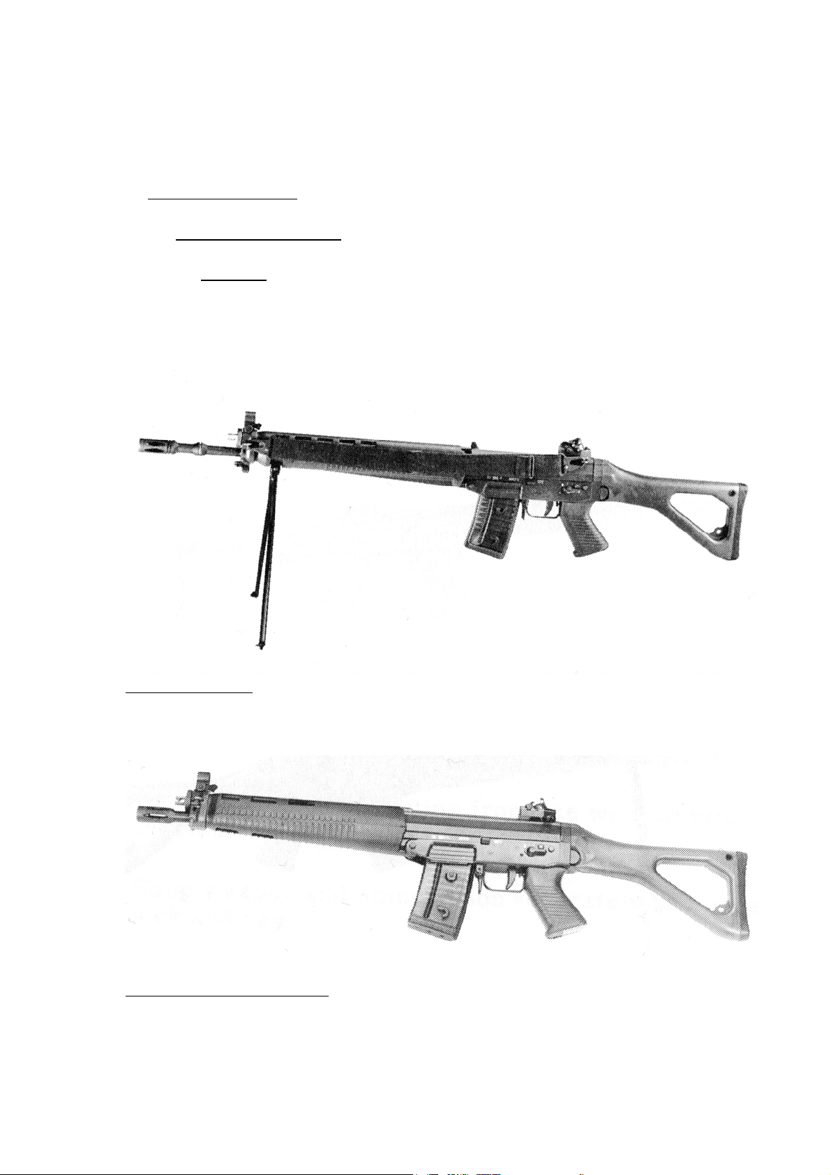
The semiautomatic SIG SG 550/551 SP is a gas operated weapon with
rotary bolt mechanism. The operation and maintenance of the standard
version SIG SG 550 and the short version SIG SG 551 are identical.
SIG SG 550 SP
Standard version with folding butt, bipod and carrying sling
SIG assault rifle SG 551
Short version with folding butt.
4
Page 5
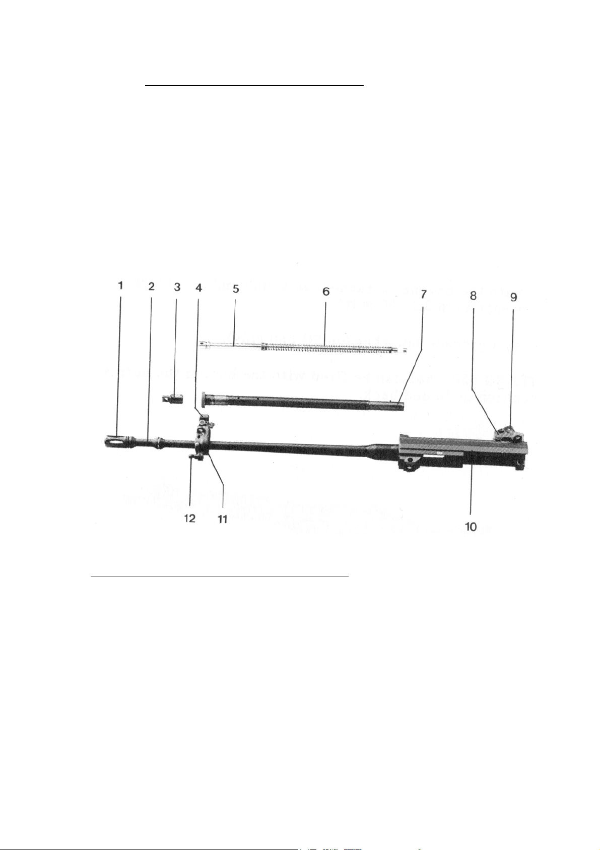
2.1.2 Barrel with receiver and gas system
The barrel is screwed into the receiver. The muzzle is fitted with a
flash suppressor. The front sight mount, which is fixed to the barrel,
contains the gas port, accepts the front sight and gas system and
also serves as a support for the handguard.
The receiver guides the bolt and houses the locking system.
The rear sight mount with diopter drum is also mounted on top of
the receiver.
Barrel with upper receiver and gas system
1. Flash suppressor
2. Barrel
3. Gas valve
4. Front sight
5. Gas piston
6. Recoil spring
7. Gas tube
8. Rear sight mount
9. Diopter drum
10.Receiver casing
11.Front sight mount
12.Bayonet lug (on SG 550 only)
5
Page 6
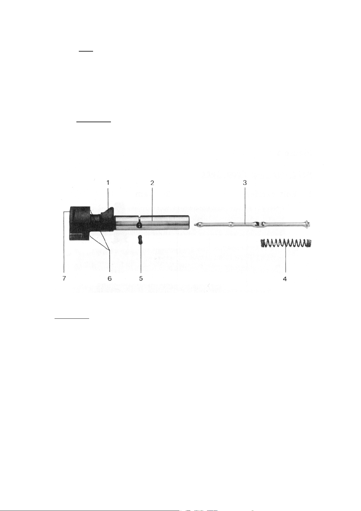
2.1.3. Bolt
The bolt consists of two main parts:
-bolt head
-bolt carrier
a. Bolt head
The bolt head locks the bolt assembly, houses the firing pin and the
extractor and feeds the cartridge to the chamber.
Bolt head
1. Control cam
2. Bolt head
3. Firing pin
4. Firing pin spring
5. Firing pin retaining stud
6. Locking lug
7. Extractor
6
Page 7
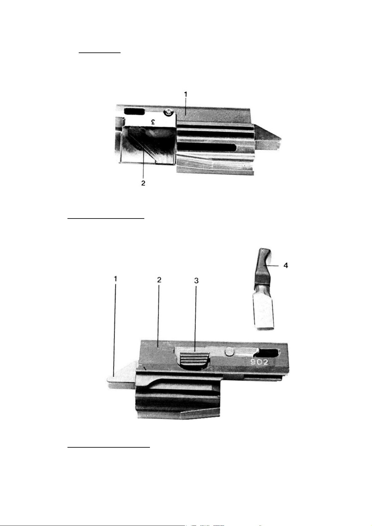
b. Bolt carrier
The bolt carrier guides the bolt head, controls the locking and
unlocking by means of the cam, connects the bolt to the gas system
and cocks the hammer.
Bolt carrier from left
1. Bolt carrier 2. Cam
Bolt carrier from right
1. Cocking lug
2. Bolt carrier
3. Bolt handle catch
4. Bolt handle
7
Page 8
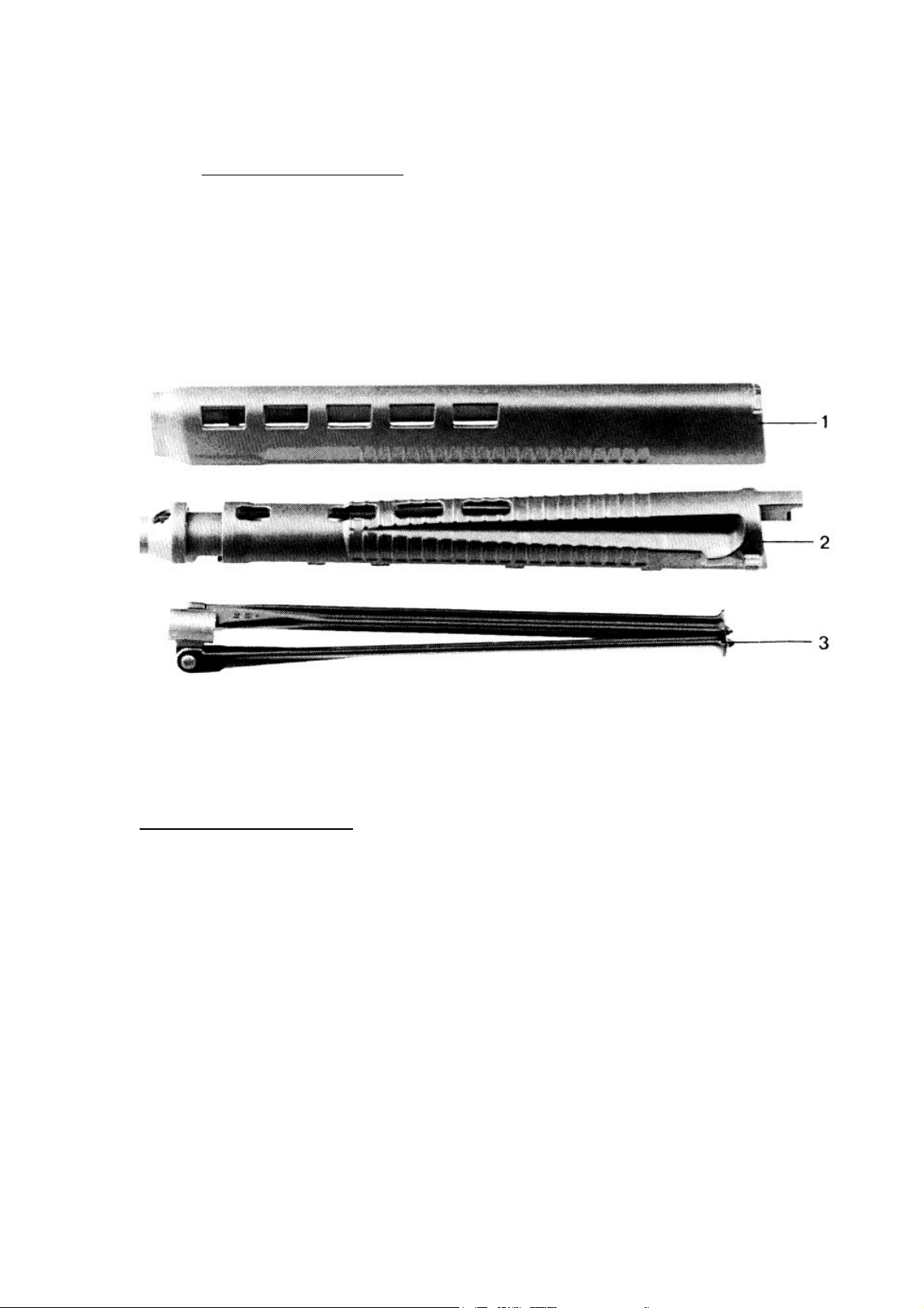
2.1.4. Handguard and bipod
The handguard protects the barrel and the gas system from damage
and provides heat protection. The bipod on the SIG SG 550 can be
used to support the rifle when firing.
Hand guard with bipod
1. Handguard, upper part
2. Handguard, lower part
3. Bipod
8
Page 9

2.1.5. Trigger assembly and butt
The trigger assembly comprises all the parts required for siring a shot.
The safety lever on both sides can be set to two positions.
Position “S”
Position “1”
By pivoting the trigger guard to the right or left side, the trigger
becomes accessible for shooting with mittens. For safety reasons the
trigger guard must not be shifted until just before firing the weapon,
and after firing it should be immediately replaced in the normal
position.
The folding butt is made of high strength synthetic material.
In the firing position it is held by the butt locking mechanism, and
when folded it’s held by spring pressure on the handguard.
The weapon is locked in the safe position.
The weapon will fire semi auto.
9
Page 10
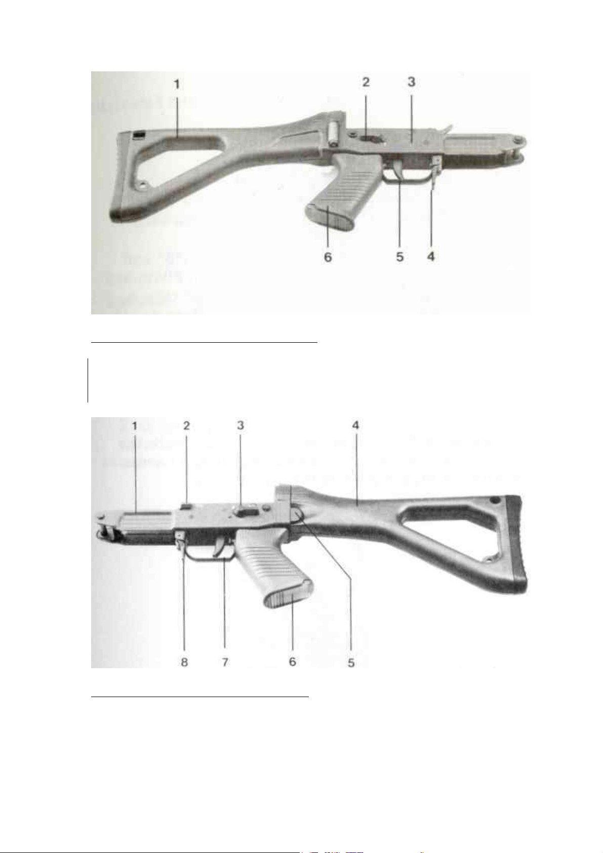
Trigger assembly and butt from right
1. Butt
2. Safety lever
3. Trigger casing
4. Magazine catch
5. Trigger
6. Pistol grip
Trigger assembly and butt from left
1. Trigger casing
2. Bolt catch
3. Safety lever
4. Butt
5. Butt catch
6. Pistol grip
7. Trigger guard
8. Magazine catch
10
Page 11

2.1.6 Sights mechanism
The sights mechanism comprises the rear sight and foresight.
The rear sight is
made up of the:
Rear sight mount
Diopter drum
Windage correction screw
Elevation correction screw
The diopter drum can be set to positions “1”, “2”, “3”, and “4”,
corresponding to firing ranges 100 m, 200 m, 300 m, and 400 m.
The positions marked in white correspond to aiming point =
point of impact.
The red “3” position corresponds to aiming point “black 6” at 300 m.
Sighting position “1” is designed for immediate firing, and two
luminous dots are fitted laterally for aiming at night.
The foresight with tunnel is fixed to its mount with the foresight screw.
A folding foresight is provided for use at with the night sights on the
diopter drum.
11
Page 12
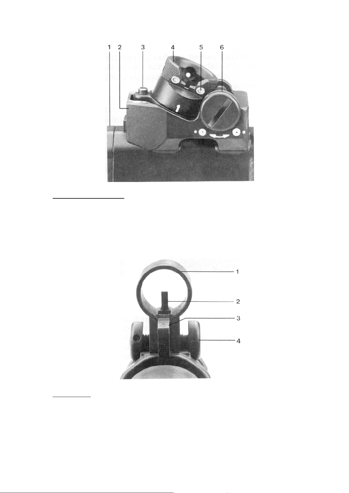
Rear sight assembly
1. Receiver casing
2. Rear sight mount
3. Elevation correction screw
4. Rear sight drum
5. Night sight
6. Windage correction screw
Front sight
1. Front sight tunnel
2. Front sight
3. Night front sight
4. Front sight screw
12
Page 13
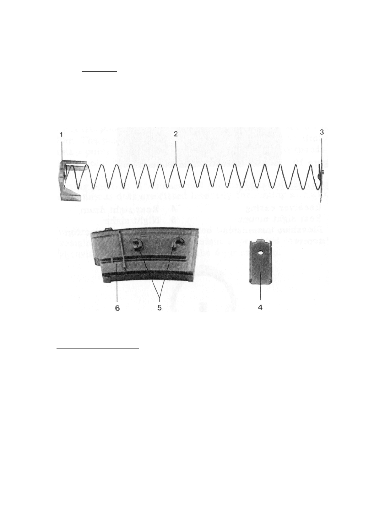
2.1.7. Magazine
The magazine is transparent and has a capacity of twenty or thirty
rounds. On either side of the casing there is a mechanism, that allows
several magazines to be connected if required.
Magazine, dismantled
1. Feeder
2. Magazine spring
3. Magazine floorplate catch
4. Magazine floorplate
5. Magazine coupling lugs
6. Magazine casing
13
Page 14

2.2. Technical specifications
SG 550 SG 551
Dimensions inches
Caliber
inches
.223 .223
Total length inches 39.29 34.53
Length with butt folded inches 30.39 25.63
Barrel
Barrel length
inches 20.78
16.02
(USA)
14.3 (others)
Number of grooves 6 6
Rifling:
SG550-1/ SG551-1 right inches 10 10
SG550-2/ SG551-2 right inches 7 7
Sights
Type Diopter sights
Sight base mm 21.26 18.34
Range adjustment m 100 to 400
yards 110 to 440
Weight
Weapon incl. empty
lb 9.03 7.49
magazine
Empty 20 rd. magazine
Empty 30 rd. magazine
Loaded 20 rd. magazine
Loaded 30 rd. magazine
oz 3.35
oz 3.87
oz 11.99
oz 16.75
3.35
3.87
11.99
16.75
Subject to change without notice
14
Page 15
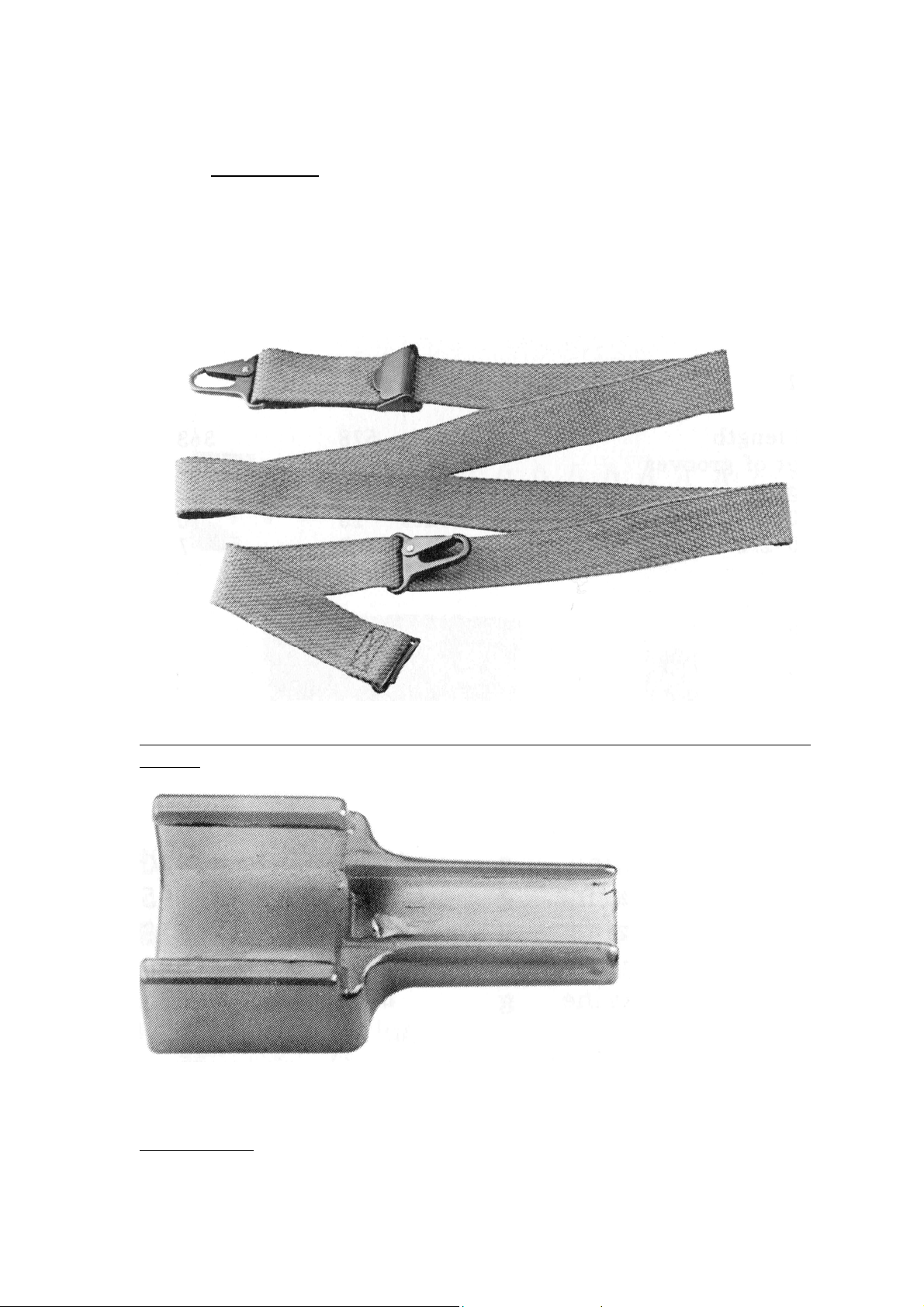
2.3. Accessories
Every SIG assault rifle SG 500/551has the following accessories:
Carrying sling
Loading aid
Cleaning kit
Carrying sling in woven nylon with two hooks, an adjustment clip and a
buckle
Loading tool
15
Page 16
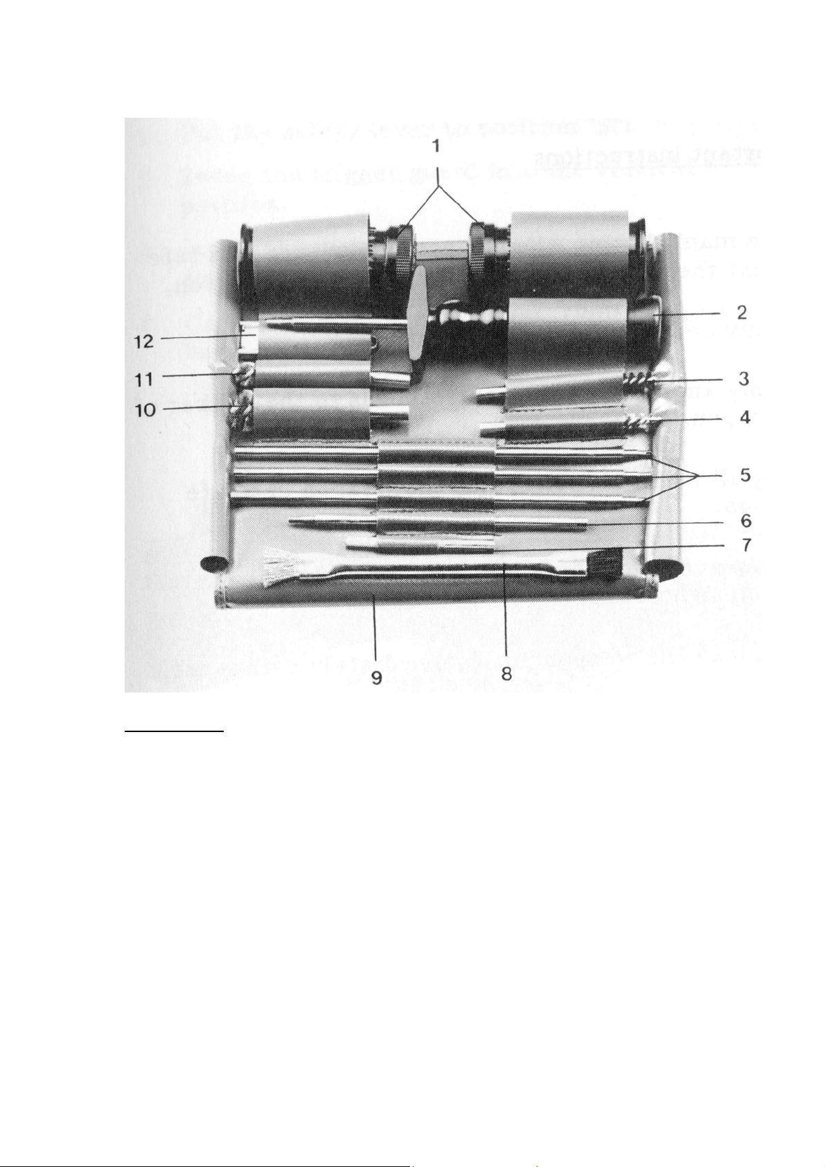
Cleaning kit
1. Weapon grease tube
2. Cleaning rod handle
3. Grease brush
4. Barrel brush
5. Cleaning rod sections
6. Extension rod with ferrule
7. Cleaning jag
8. Cleaning brush
9. Simileather case
10. Gas tube brush
11. Chamber cleaning tool
12. Barrel inspection mirror
16
Page 17

3. Handling
3.1 Important instructions
Before manipulation the weapon, make sure that it is safe and
that the trigger guard is put in the vertical position.
Use only commercial grade ammunition.
Use only ammunition that corresponds to the caliber of the
weapon.
During all manipulations point the weapon in a safe direction.
Do not place your finger on the trigger until the target has
been sighted.
Do not load the weapon until immediately before use.
Unload weapon immediately after shooting is finished.
Detach bolt and magazine from the weapon prior to
transportation.
17
Page 18
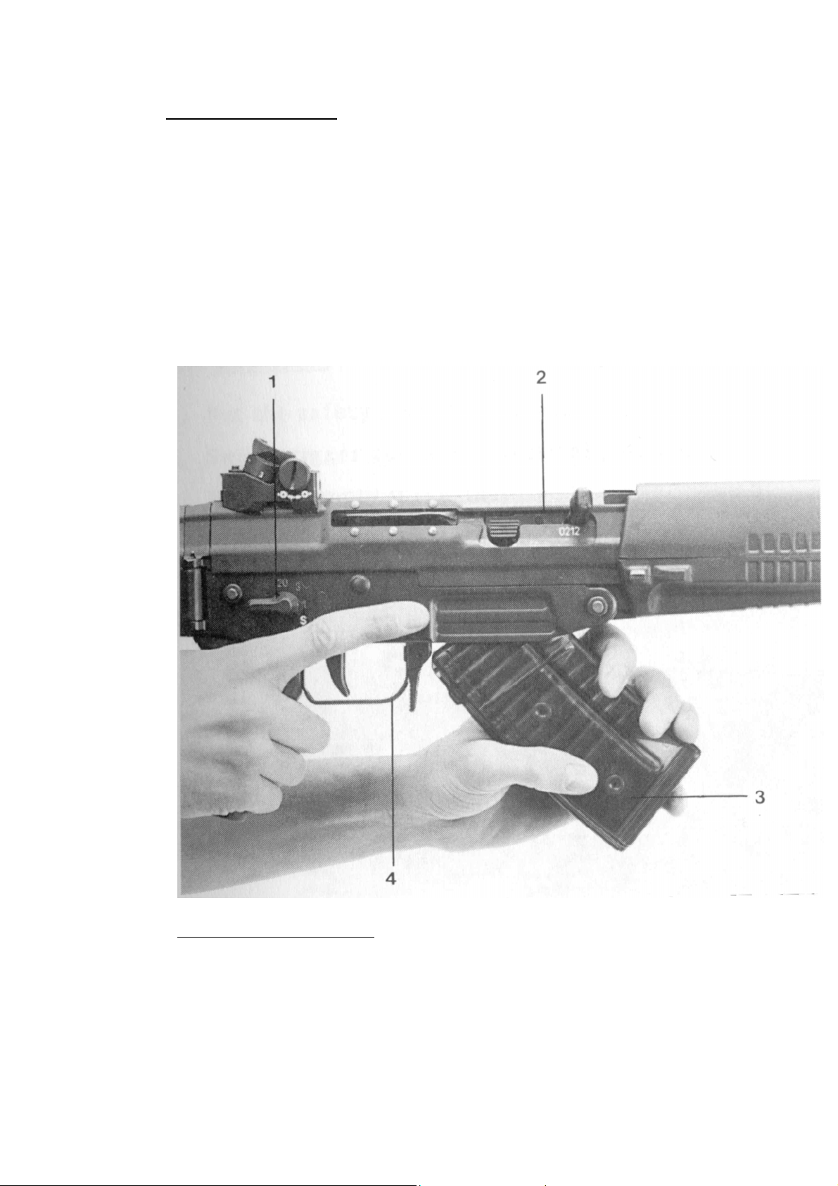
3.2. Loading the weapon
1. Put the safety lever to position “S”;
2. Swing the trigger guard into the vertical position;
3. Insert the magazine and check that it is properly seated by
pressing forward;
4. Carry out loading movement. (Pull the bolt handle fully back
and let it fly forward)
Inserting the magazine
1. Safety lever
2. Bolt
3. Magazine
4. Trigger guard
18
Page 19
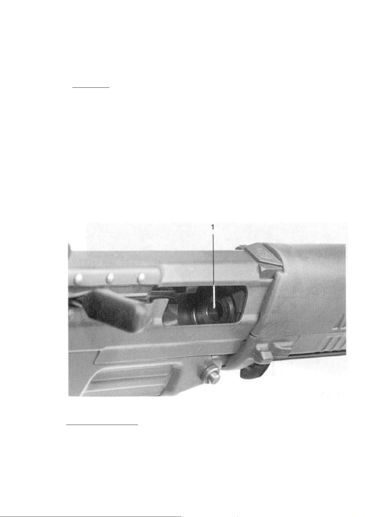
3.3. Unloading
1. Put safety lever to position “S”;
2. Swing trigger guard into vertical position;
3. Remove magazine by pressing magazine catch;
4. Carry out loading movement, with bolt retracted check for
empty chamber;
5. Switch safety lever to “1”, pull trigger (with weapon pointing
downrange), switch safety lever to “S”.
Check the chamber
1. Chamber
19
Page 20
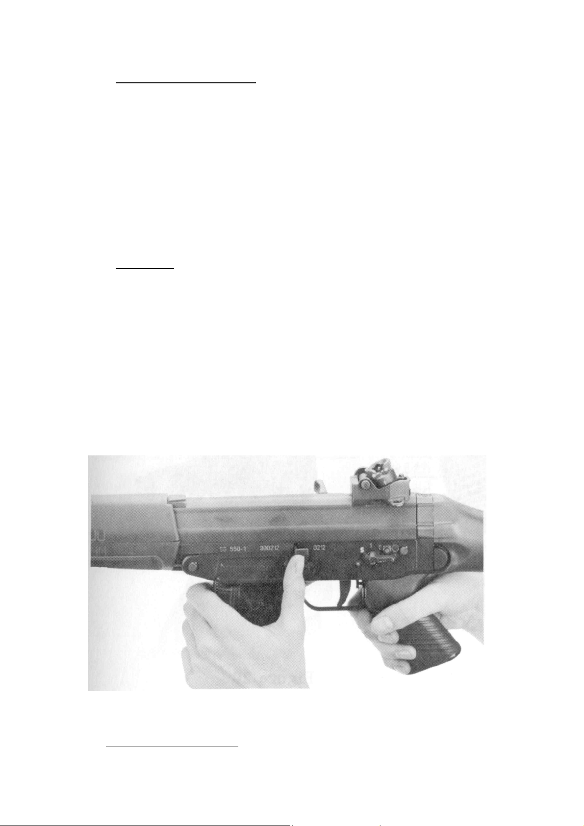
3.4. Changing the magazine
1. Put safety lever to position “S”;
2. Swing trigger guard into vertical position;
3. Remove magazine;
4. Insert loaded magazine and check that it is properly seated by
pressing forward.
3.5. Reloading
1. Put safety lever to position “S”;
2. Swing trigger guard into vertical position;
3. Remove magazine;
4. Insert loaded magazine and check that it is properly seated
by pressing forward;
5. Push the bolt catch up or pull back the bolt handle slightly and
allow the bolt to fly forward.
Push the bolt catch up
20
Page 21
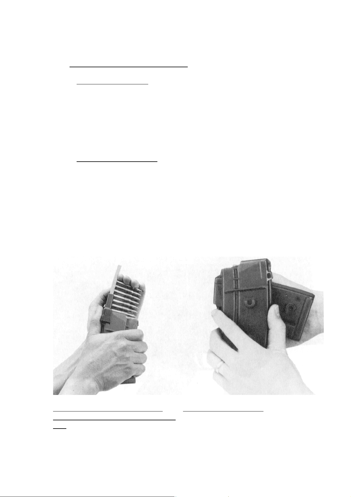
3.6. Filling and coupling of magazines
3.6.1. Filling the magazine
1. Place the tool on magazine;
2. Insert the ammunition clip and press cartridges into
magazine;
3. Remove loading tool.
3.6.2. Coupling of magazines
1. Hold magazine vertically;
2. With the floorplate of the second or third magazine pointing to
the rear, firstly connect the upper lugs, the rotate forward and
connect lower lugs.
Coupling of more than three magazines in sequence is not
recommended.
Loading the cartridges into the
magazine by means of the loading
tool
Coupling of magazines
21
Page 22
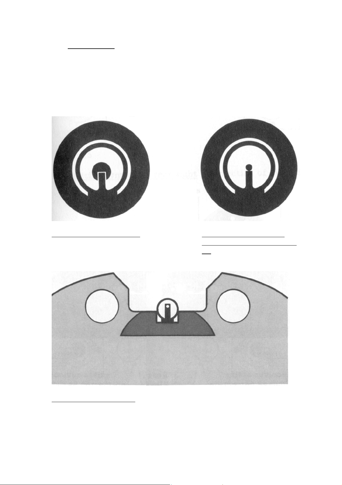
3.7. Aiming, firing
To aim, align the eye, diopter or battle sight, foresight and target.
When using the diopter, ensure that the periphery of the foresight
tunnel and the diopter aperture are concentric.
At all ranges the foresight should be aimed at the center of the target.
Firing is therefore to point of aim.
Sight picture point of aim
Sight picture night sight
Bull’s eye 6 o’clock with
sight setting “red 3” at 300
m.
22
Page 23
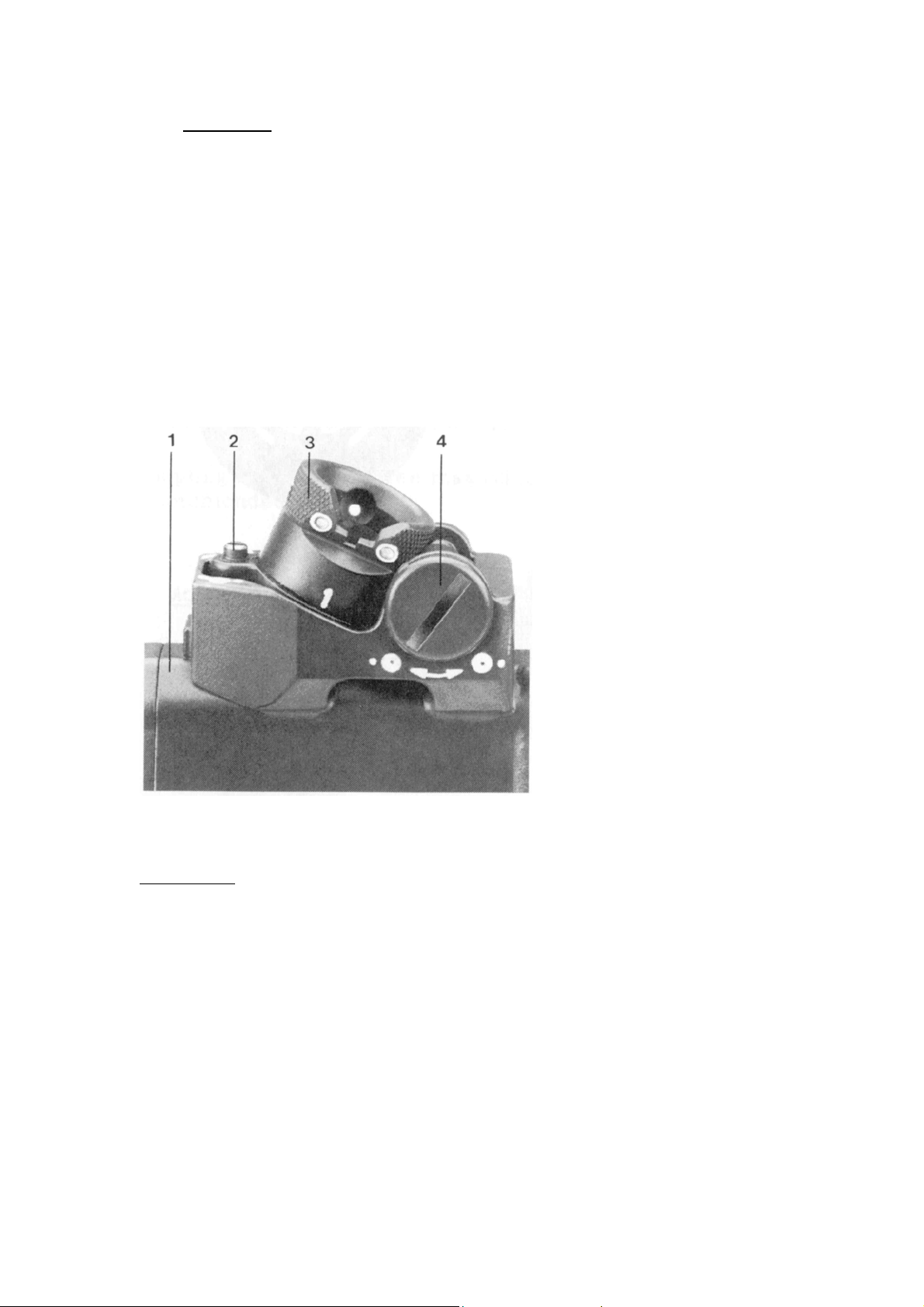
3.8. Adjusting
To correct for elevation and windage, the corresponding correction
screw is turned with a screwdriver.
By rotating the elevation correction screw and the windage correction
screw by one click, the average point of impact in the vertical
respectively the horizontal axis is displaced by approximately 0.15
o
/oo.
Rear sight
1. Receiver casing
2. Elevation correction screw
3. Rear sight drum
4. Windage correction screw
23
Page 24
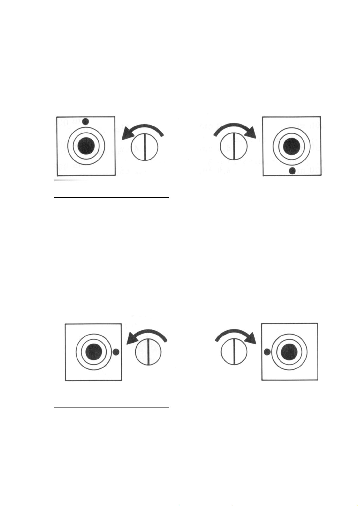
Elevation:
High shots are corrected by turning the elevation correction screw to
the left.
Low shots are corrected by turning the elevation correction screw to
the right.
Correction symbol on rear sight
Windage:
Shots to the right are corrected by turning the windage correction
screw to the left.
Shots to the left are corrected by turning the windage correction screw
to the right.
(correction of elevation)
Correction symbol on rear sight (correction of windage)
24
Page 25

Firing range Average point of impact correction per notch
100 m
200 m
300 m
400 m
To correct for elevation or windage, the corresponding correction screw
is turned with a screwdriver.
SG 550
1.5 cm
3.0 cm
4.5 cm
6.0 cm
SG 551
1.8 cm
3.6 cm
5.4 cm
7.2 cm
25
Page 26
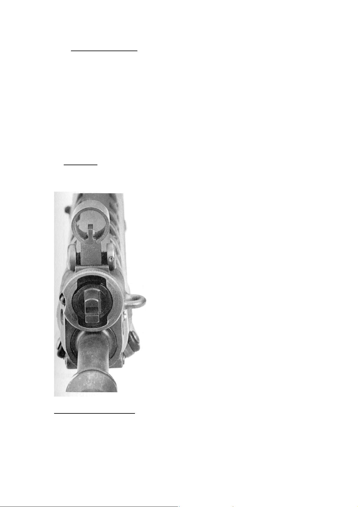
3.9. Gas valve position
With the SIG SG 550/551, the gas volume required for the function of
the weapon can be controlled by adjusting the gas valve.
a. Position I
Under normal conditions, firing is effected in this position.
(Rib of gas valve in vertical position)
Gas valve in position I
26
Page 27
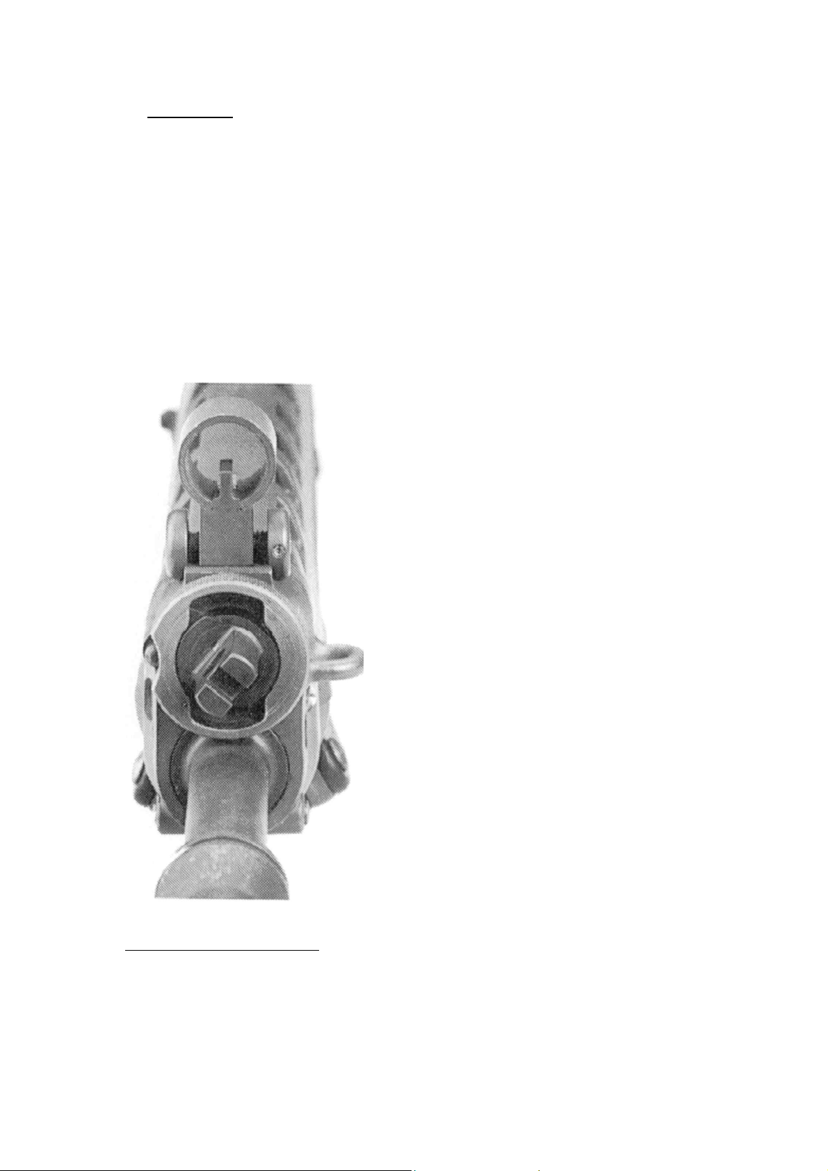
b. Position II (Rib of gas valve in slanting position)
When cycling or ejection problems are encountered due to heavy
fouling or icing-up, the gas valve is to be turned clockwise as far as the
stop. In this position, a larger gas quantity acts on the gas piston.
The adjustment of the gas valve is effected manually, and, in case of a
hot or heavily fouled weapon, by means of a cartridge or auxiliary aid.
Firing with the gas valve in position II is an exception. As soon as the
weapon works, the gas valve must be turned back to position I,
otherwise the recoil is intensified and the weapon is unnecessarily
stressed.
Gas valve in position II
27
Page 28
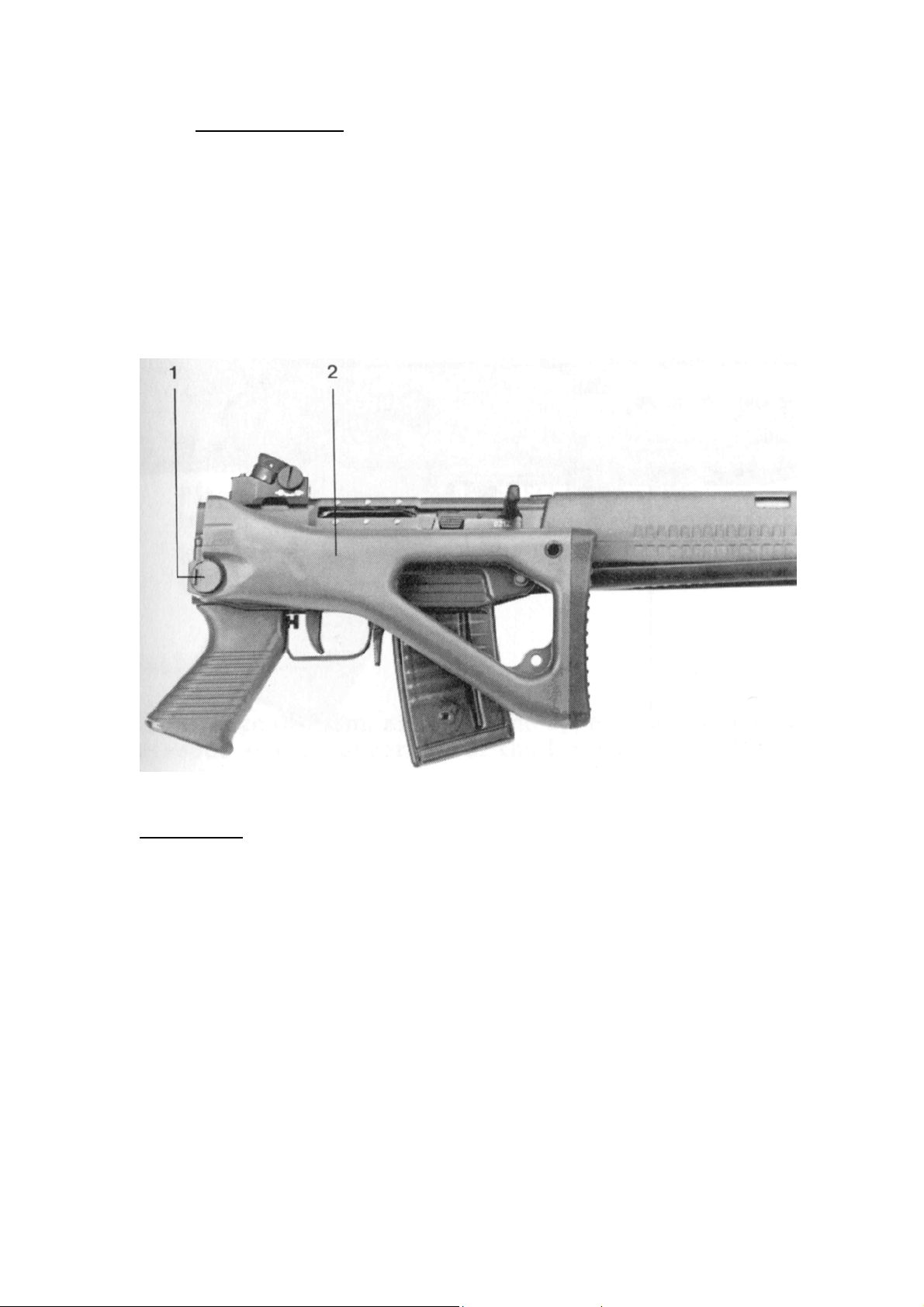
3.10. Folding the butt
Thumb in the butt catch and fold the butt so that it registers with the
handguard under spring pressure.
Butt folded
1. Butt catch
2. Butt
28
Page 29
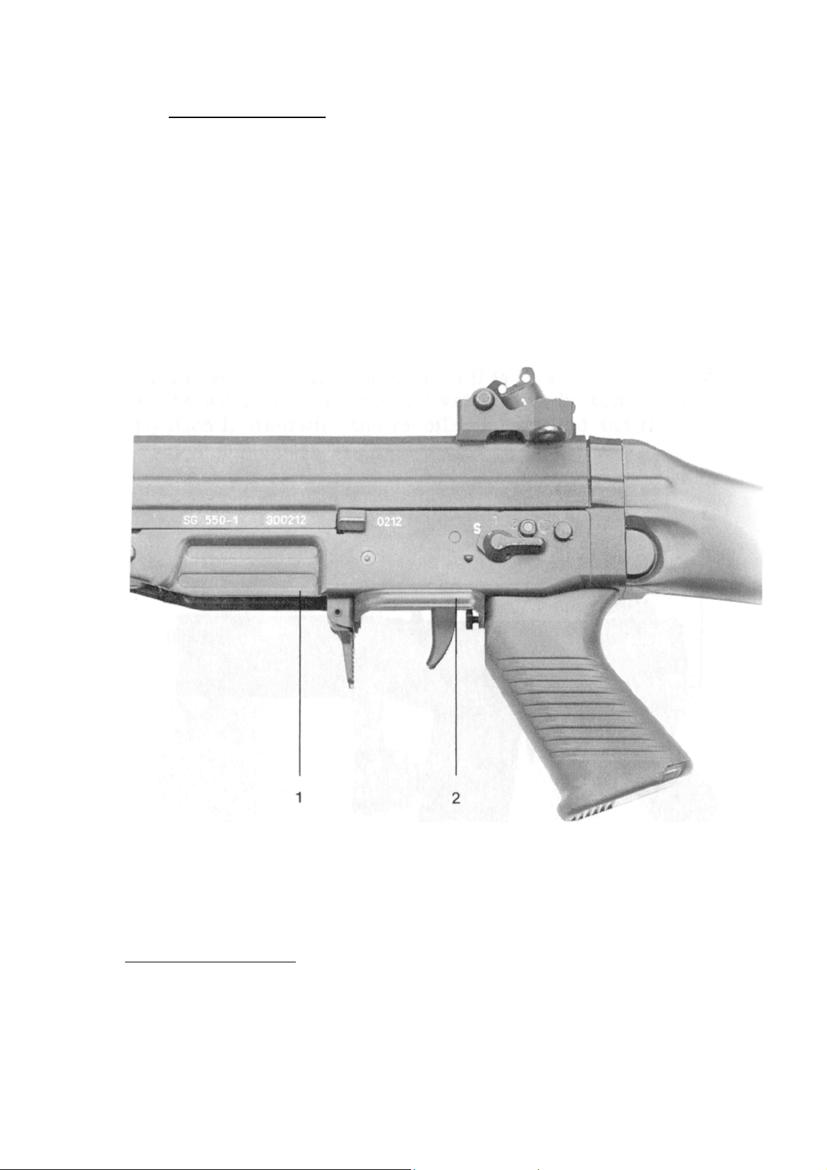
3.11 Firing with mittens
For firing with mittens the trigger guard can be pivoted to the left or
right.
For safety reasons the trigger guard must be placed in the vertical
position before carrying out any manipulations.
Trigger guard folded
1. Trigger casing
2. Trigger guard
29
Page 30
3.12. Use of accessories
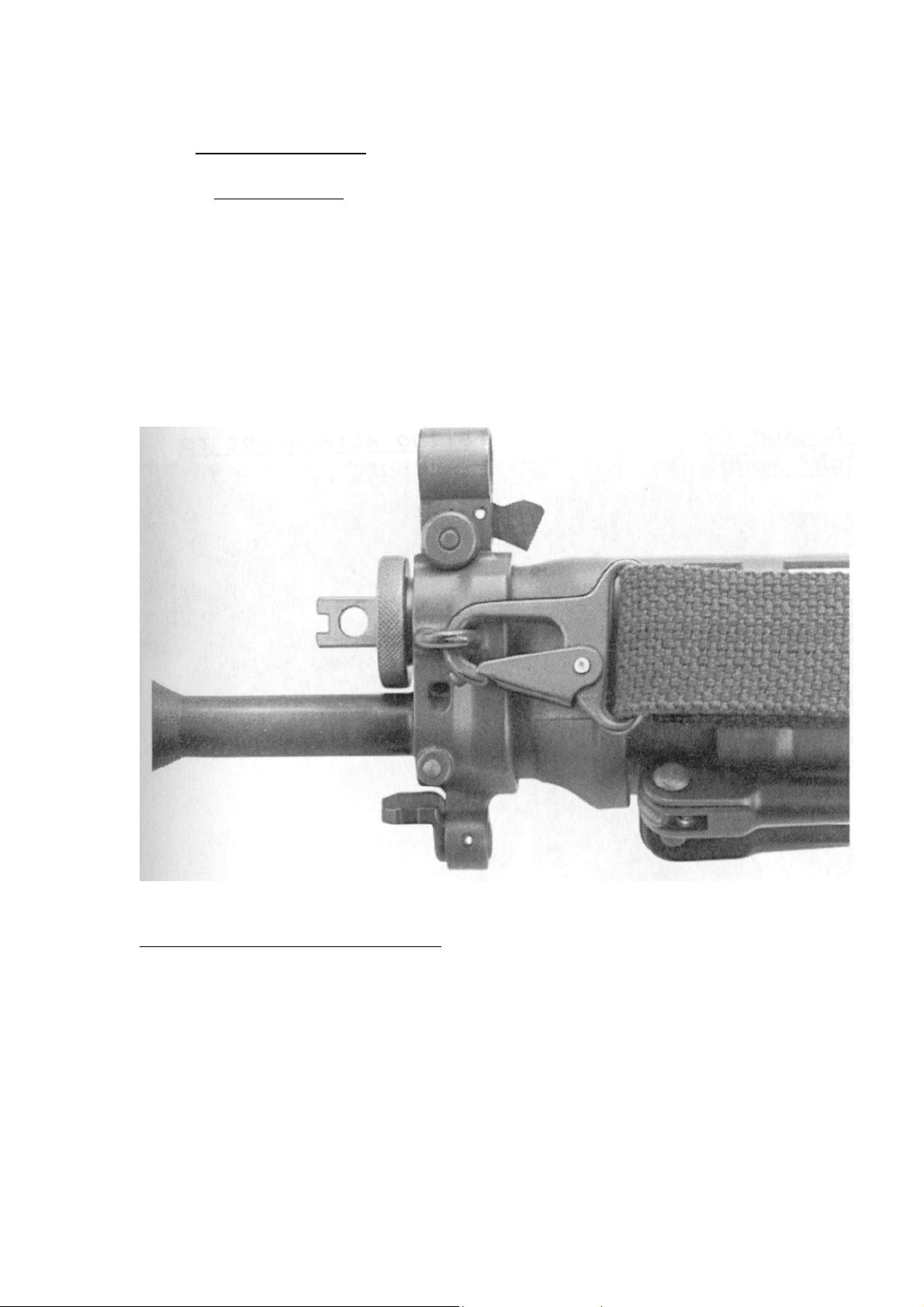
3.12.1. Carrying sling
One end of the sling hooks into the lug on the foresight mount, the
other end is attached to the butt.
To fix the taut sling, use the clip.
To maintain a taut sling, slip the clip over the sling strap.
Sling hooked to foresight mount
30
Page 31
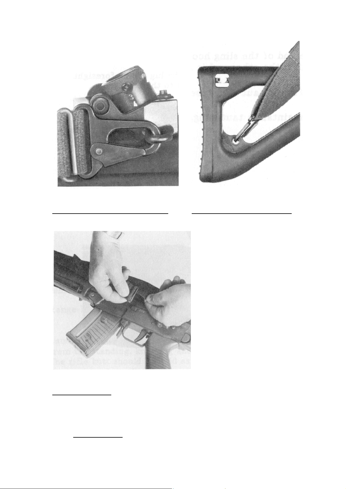
Sling hooked to rear sight mount
Sling attachment to the butt
Fix the taut sling
3.13. Field stripping
31
Page 32
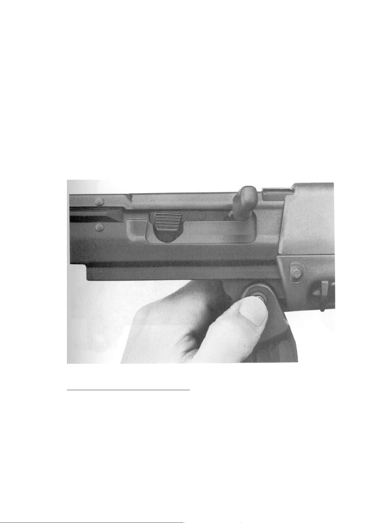
1. Unload weapon;
2. Remove carrying sling;
3. Press the rear trigger casing stud from both sides and withdraw
it from the stud head side as far as the stop;
4. Lay the weapon on its left side and swing out the trigger
assembly;
5. Withdraw the front trigger casing stud as described in point 3
and remove the trigger assembly;
Remove the trigger housing stud
6. Press down the bolt handle catch and remove the bolt handle;
32
Page 33
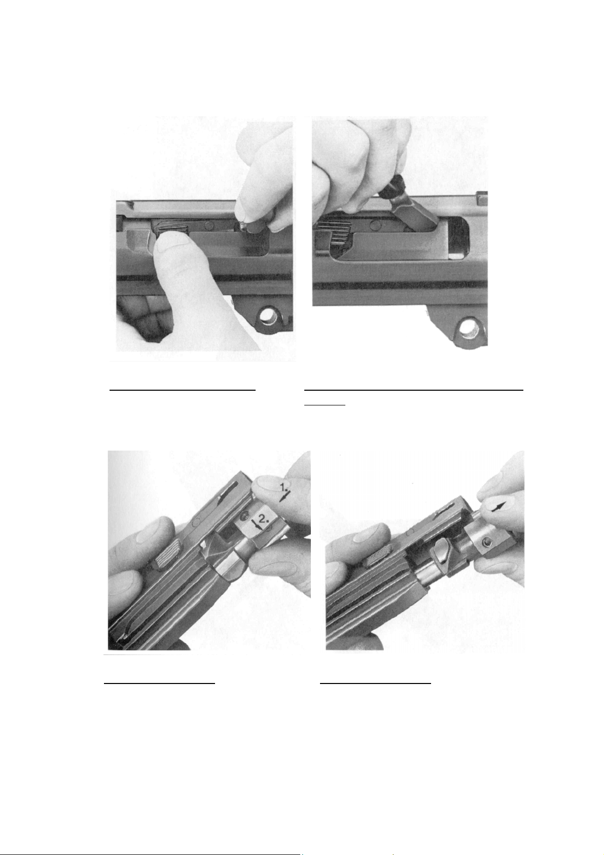
7. Use the bolt handle to push the bolt to the rear, remove the
bolt from the receiver;
Remove the bolt handle
8. Twist the bolt head to remove it from the bolt carrier;
Push the bolt to the rear, using bolt
handle
Remove bolt head
Remove bolt head
33
Page 34
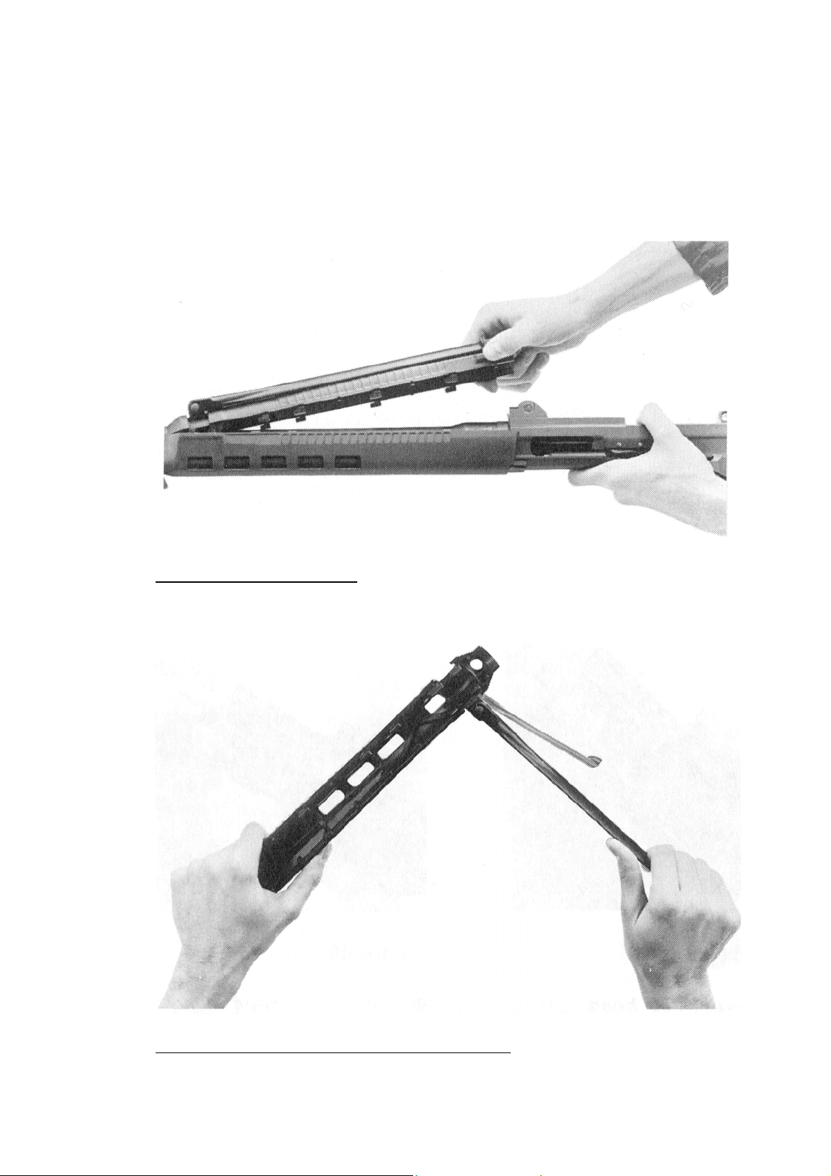
9. Pull lower handguard to the rear and remove; swing out the
bipod legs and remove laterally;
10. Lift upper handguard at the rear and remove at the front sight
mount;
Lift off lower handguard
Remove bipod carrier from the handguard
34
Page 35
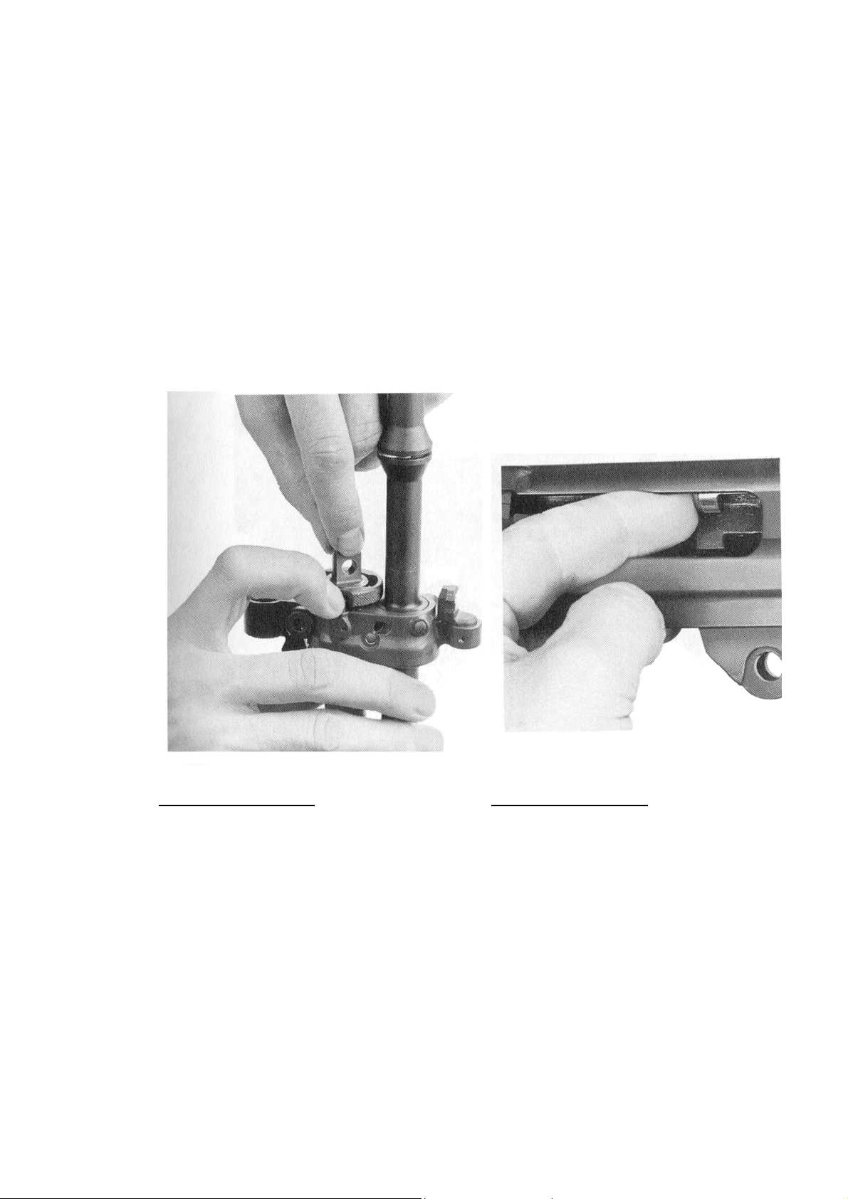
11. Press in the gas valve catch, remove the valve by
simultaneously rotating it and pulling it forward;
12. Push the Gas piston and recoil spring forward, reaching through
the ejection port, and extract them from the front;
13. Press down the gas-valve catch and rotate the gas tube through
o
90
so that the notch on the headpiece lies on the barrel;
14. Pull the gas tube out from the front end;
Remove gas valve
Push in gas piston
35
Page 36
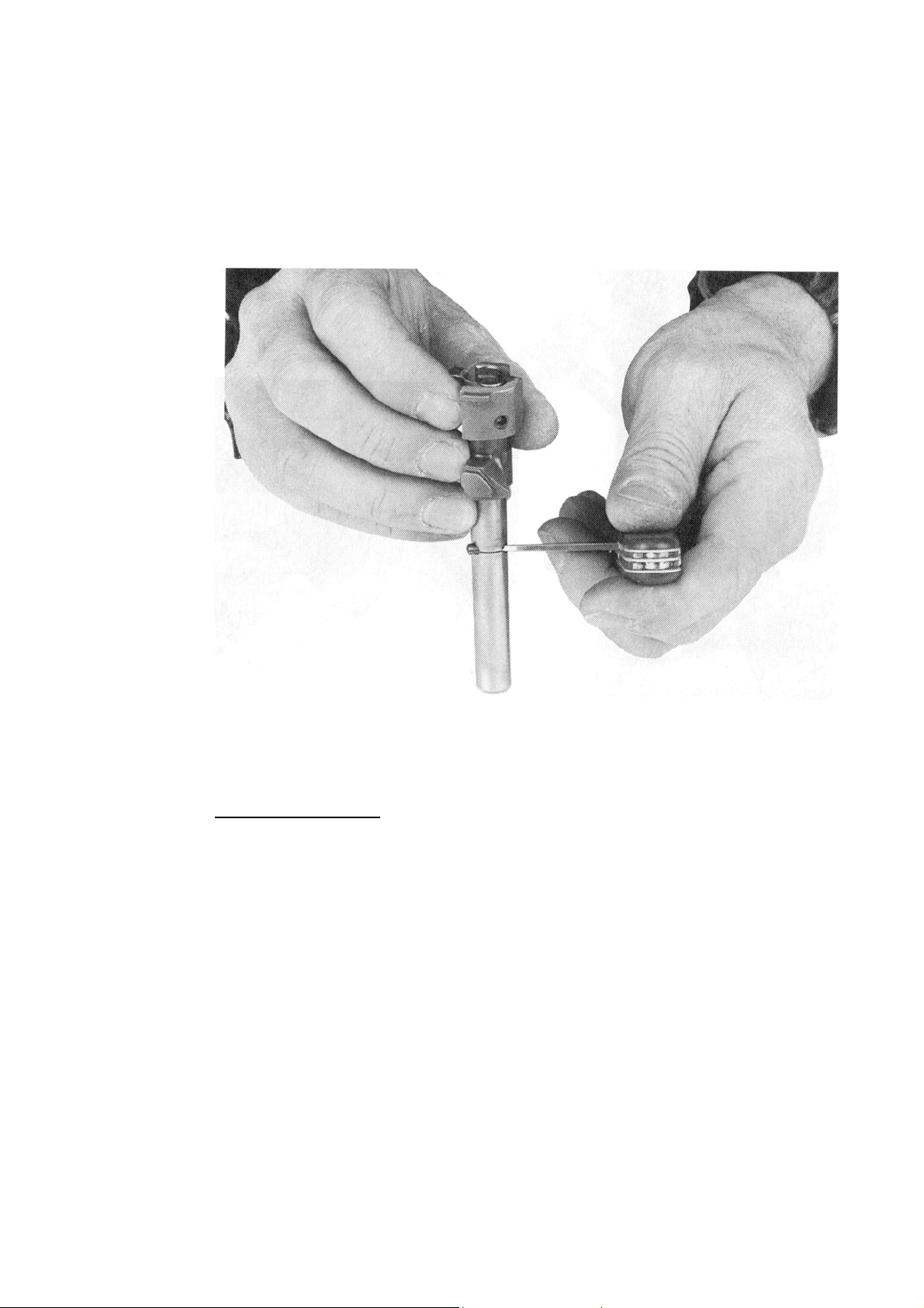
15. Remove the firing pin:
Hold the bolt head against a firm surface in such a way that
the firing pin is completely pressed into the bolt head;
Remove the retention pin using a knife-edge and extract
the firing pin and spring;
Figure 45
Remove firing pin
36
Page 37
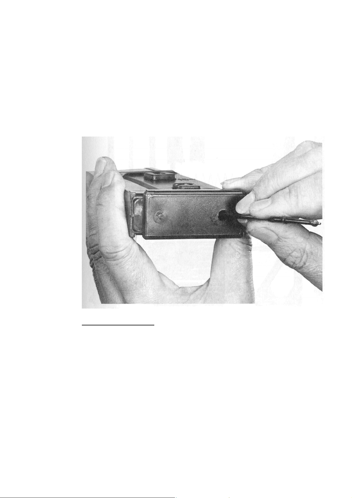
16. Dismantle the magazine;
Press in the retention plug of the magazine floorplate with
the thick end of the firing pin. Pull the magazine floorplate
out from the rear;
Pull out the floorplate catch along with the spring and
follower.
Dismantle magazine
37
Page 38
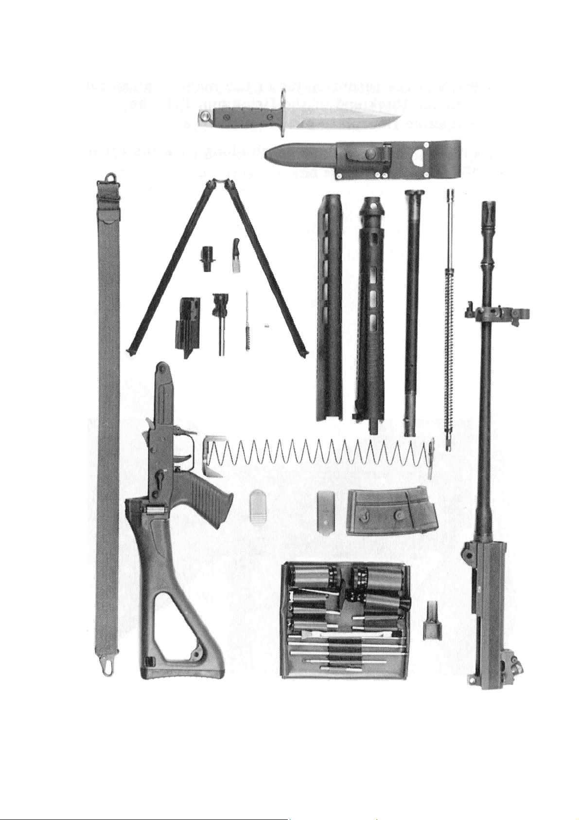
Figure 47
38
Page 39
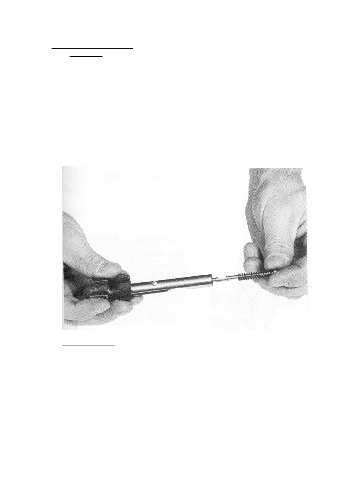
SIG SG 550 dismantled
3.14 Assembly
The weapon should always be reassembled in the reverse order of
stripping:
1. Assemble magazine;
2. Insert firing pin:
Slip the firing pin into the bolt head.
Ensure that the notch is correctly placed to accept the
retention stud;
Push the firing pin into the bolt head an secure it with the
retention stud as soon as the notch is flush with the bore;
Insert firing pin
Correct position of the notch
39
Page 40
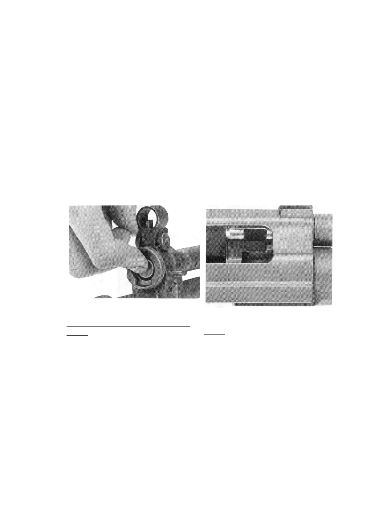
3. Install the gas tube:
Slip the gas tube (flange notch pointing downwards)
through the bore of the foresight mount and insert the
end into the corresponding opening in the receiver;
Press the gas tube against the foresight mount and turn
it through 90o to the right so that the retention stud of
the gas valve registers in the flange;
4. Insert the piston with the recoil spring:
Insert the piston, with its retention notch slide facing
against the barrel, into the gas tube;
Check with forefinger that the gas piston moves freely in
the tube;
Check correct position with index
finger
Correct position of retention
notch
40
Page 41
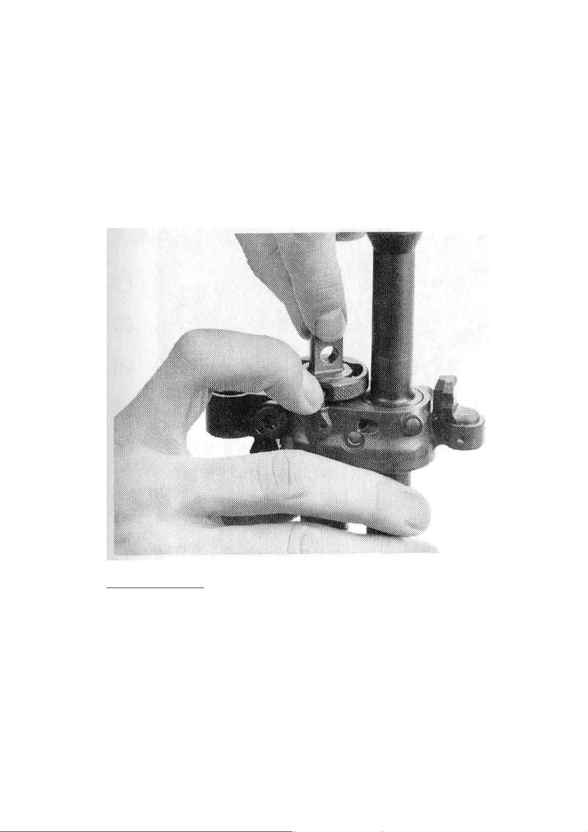
5. Install the gas valve:
With the notch for retention stud facing downwards in
the flange of the gas tube;
Press in the catch and turn the gas valve to the right up
to position I;
Check that the gas valve catch has registered;
Install gas valve
6. Install the upper handguard;
7. Attach the bipod;
8. Install the lower handguard;
9. Assemble bolt head and carrier;
41
Page 42
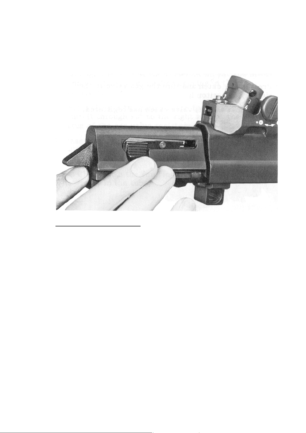
10. Insert bolt assembly:
Slide bolt head completely to the front by pressing firing
pin;
Slide bolt into receiver casing.
Inserting the bolt assembly
11. Insert the bolt handle into its slot in the bolt carrier and check
that it has registered with the catch
12. Install trigger casing:
Ensure that the holes in the front trigger casing stud
overlap;
Press the trigger casing stud through as far as the
stop;
Tilt up the trigger casing and fix with rear trigger
casing stud.
13. The function check should be carried out in accordance with
section 3.16;
42
Page 43

3.15 Function check
The function check described below is to be made after every stripping.
1. Unload per Section 3.3;
2. Make sure that bolt handle is engaged in correct position;
3. Functions:
a. Safety lever set to “S”, carry out loading movement, pull the
trigger:
The hammer must not trip, the trigger must be blocked;
b. Safety lever set to “1”, pull the trigger and hold it:
The hammer must trip
Carry out loading movement with trigger being pulled:
The hammer must not trip;
Release the trigger and pull it again:
The hammer must trip;
c. Loading movement:
Safety lever on “1”: verify several times that there is a
discernible pressure point;
4. Insert empty magazine and check firm seating;
5. Bolt catch;
a. Carry out loading movement;
The bolt must be retained in the rear position;
b. Push up the bolt catch:
The bolt must run forward;
Check engagement of folded butt, pull the trigger and
put the weapon on safe.
43
Page 44

3.16. Procedure in case of malfunction
Whenever a SIG SG 550/551 SP no longer works due to a malfunction,
proceed as follows:
Carry out loading movement;
Continue firing;
If the weapon does not fire:
Insert a fresh magazine;
Loading action;
Continue firing;
If the weapon still does not fire:
Put weapon on safe;
Remove magazine;
Loading action, hold the bolt in rearmost position, check ejection
of cases and, if necessary, remove any jammed cases or
cartridges;
Turn gas valve to position II when weapon is heavily fouled or
iced up;
Insert a fresh magazine and load;
Set safety lever to the desired firing mode, continue firing;
44
Page 45

If the weapon still will not fire:
Put weapon on safe;
Unload per Section 3.3;
Clean weapon in accordance with section 4.1;
Take up firing position;
Load;
Set safety lever to the desired firing mode, continue firing;
If the weapon can not be unloaded or the fault rectified by the rifleman
in accordance with the operating instructions, a trained expert must be
consulted. The following points must be borne in mind:
If the weapon can not be unloaded immediately and there is any
danger that of self-ignition due to a hot barrel (140oC), wait at
least 15 minutes.
The weapon must remain in position as long as it is loaded.
Spectators and other unnecessary persons must be sent away so
that the problem can be tackled carefully without disturbance.
As long as the weapon is loaded, only trained experts should be
allowed to manipulate the weapon.
Malfunctions can largely be avoided by:
Cleaning the weapon according to item 4.1. after each period of
firing, at the latest just after setting the gas valve to position II.
Carrying out cleaning in accordance with the regulations
Loading the magazine correctly.
45
Page 46

4. Maintenance
4.1 Cleaning
The SIG SG 550/551 SP must be cleaned after each period of shooting.
The following sequence must be adhered to:
1. Unload weapon per section 3.3.;
2. Field strip the weapon (see Section 3.13.);
3. Clean the barrel and cartridge chamber from the rear.
4. Clean the other parts of the weapon;
5. Lubricate the barrel and chamber using oil or grease;
6. Smear the other parts of the weapon lightly with gun oil or
grease;
7. Reassemble the weapon in accordance with Item 3.14;
8. Carry out function check in accordance with Item 3.15.
46
Page 47
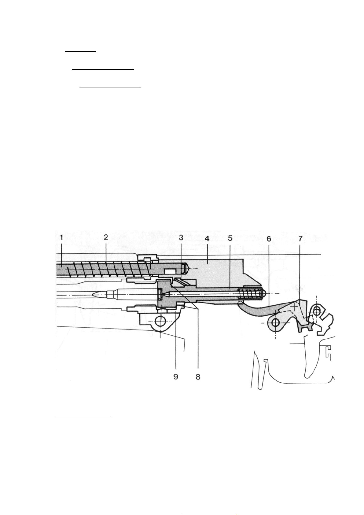
5. Function
5.1. Weapon function
5.1.1. Readiness to fire
At the moment of readiness to fire the bolt is closed and locked.
The recoil spring [2] holds the bolt carrier [4] in the front final
position, via the gas piston[1];
The bolt head [5] is rotated by the control cam [3] of the bolt
carrier [4] in such a way that its locking lugs [8] engage in the
corresponding recesses of the locking piece [9];
In this position the hammer [7] is cocked and the release bar [6]
is depressed.
Weapon loaded
47
Page 48
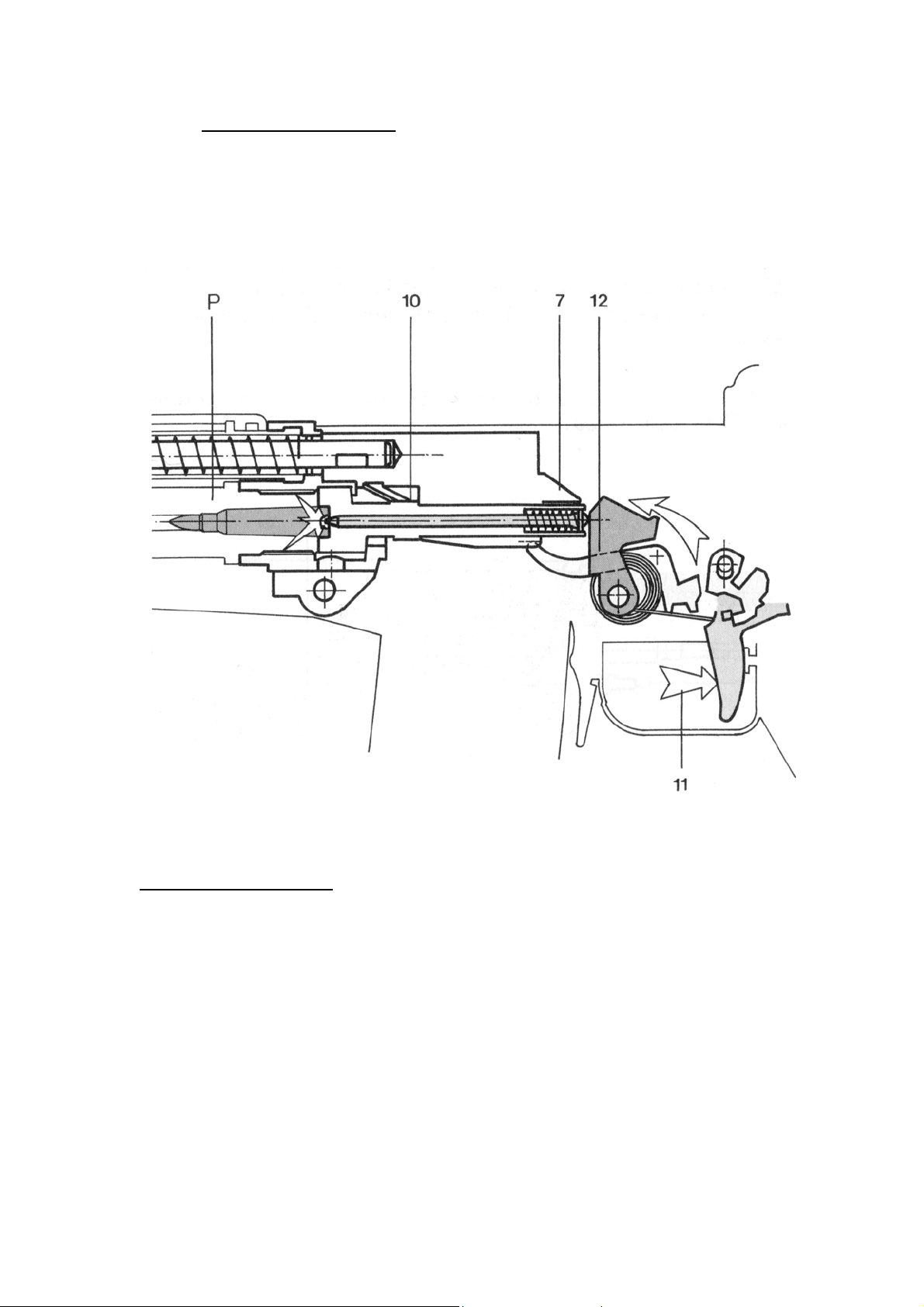
5.1.2. Discharging the shot
By pressing the trigger [11] the hammer [7] is released. The hammer
is under pressure from the main spring [12] and strikes the firing pin
[10] which, in turn, impacts against the cartridge primer of the
cartridge [P] thus discharging the shot.
Discharging the shot
48
Page 49
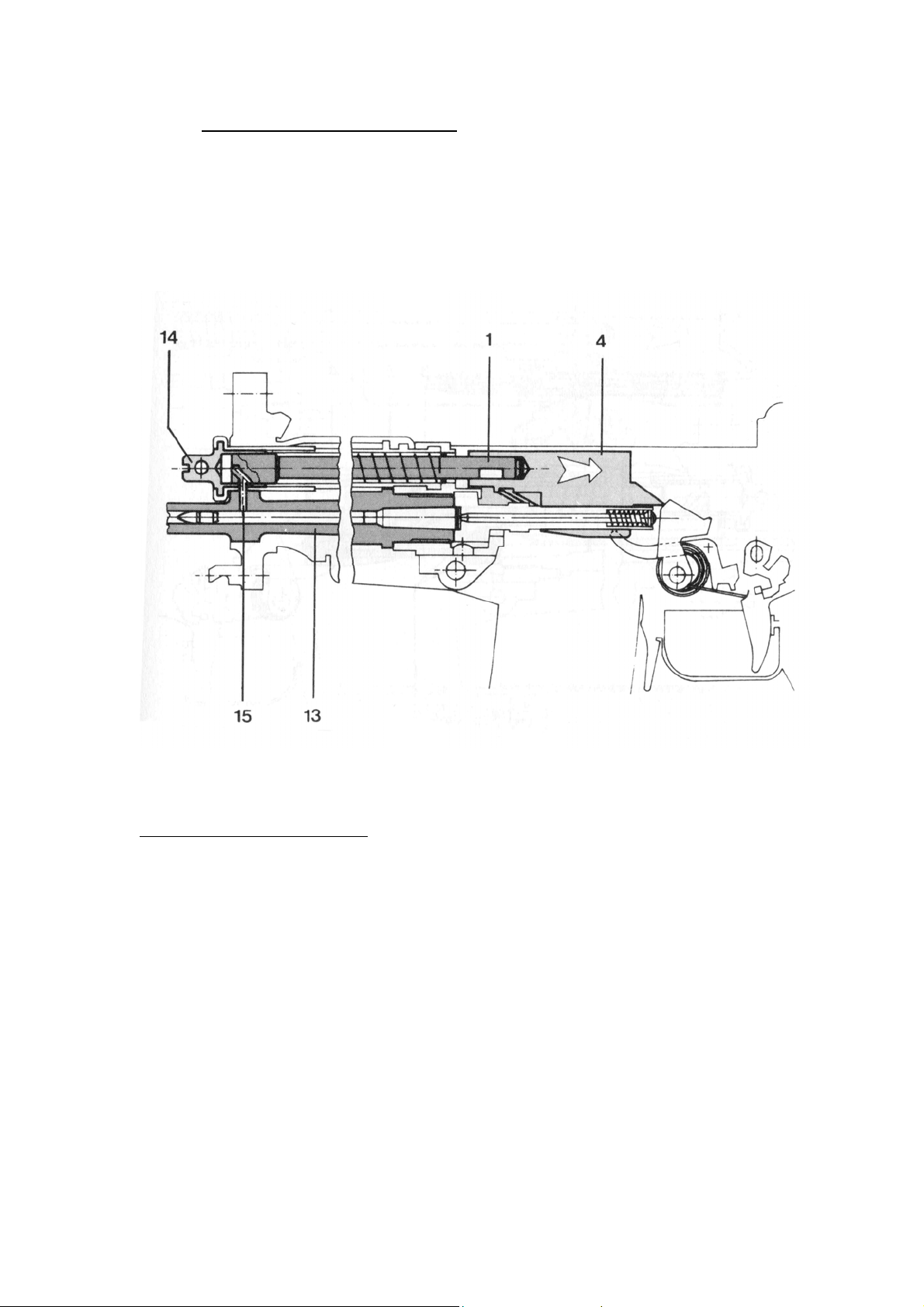
5.1.3. Unlocking and recoil of bolt
The gas pressure, generated by the burning powder, drives the bullet
up the barrel [13]. As soon as the projectile passes the gas port [15],
the propellant gas flows through the adjustable gas valve [14]. The gas
pressure acts on the gas piston [1] which pushes the bolt carrier to the
rear.
Bolt carrier recoil begins
49
Page 50
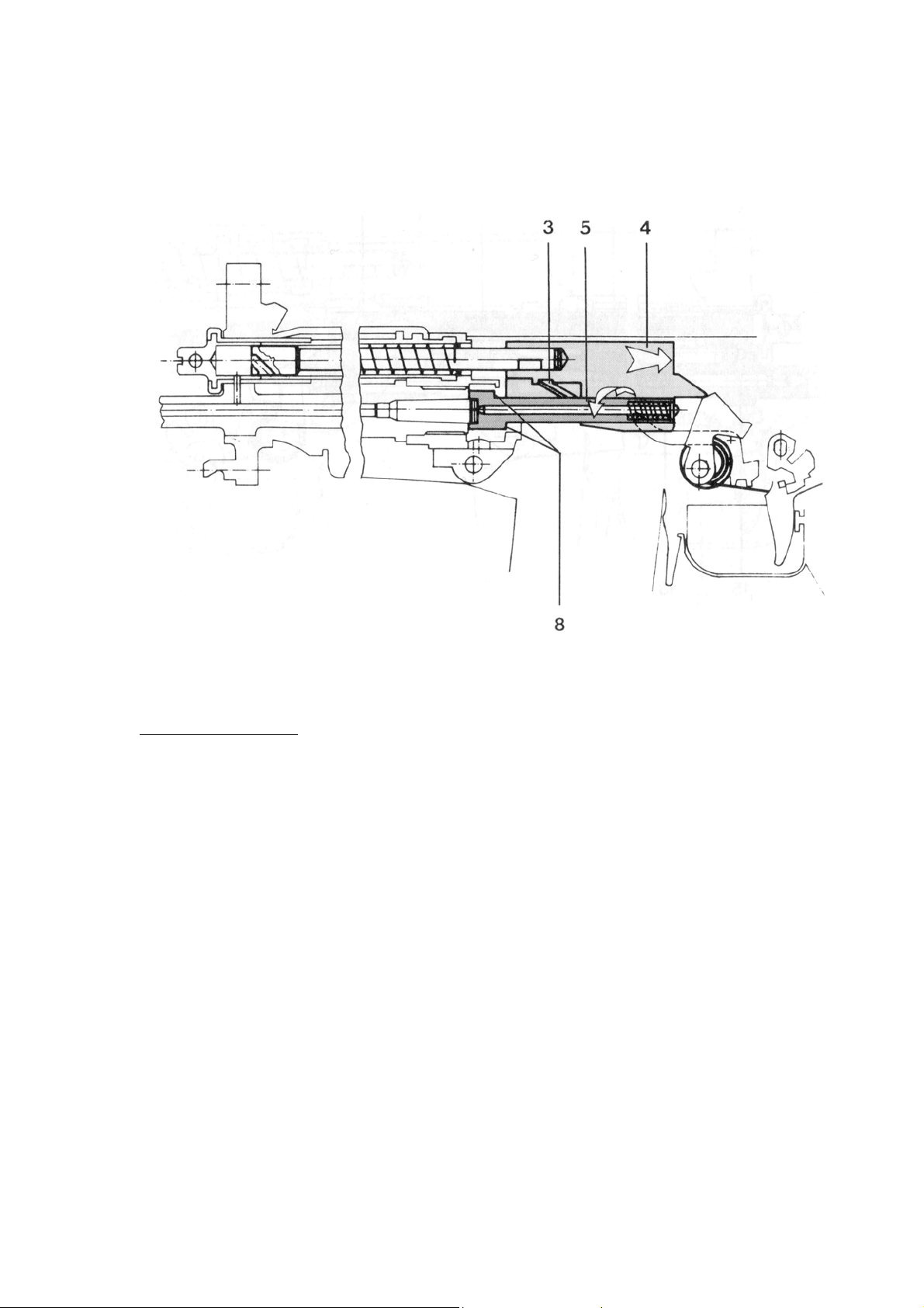
During the rearward motion of the bolt carrier [4] the bolt head [5] is
rotated by the control cam [3] so that the locking lugs [8] are
disengaged. The bolt is now unlocked.
Unlocking begins
50
Page 51
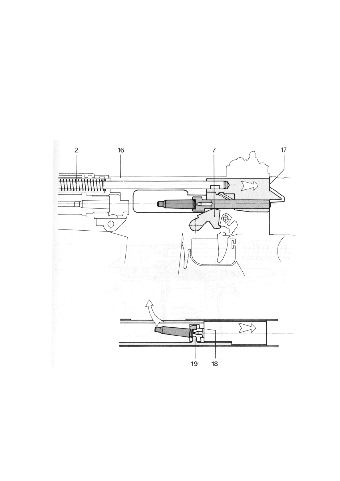
The bolt assembly moves back along the rails in the receiver [16] as
far as the stop [17] whereby:
The recoil spring [2] is compressed;
The hammer [7] is cocked;
The extractor [18] extracts the case from the chamber;
The ejector [19] ejects the case through the port in the receiver
[16].
Case ejection
51
Page 52
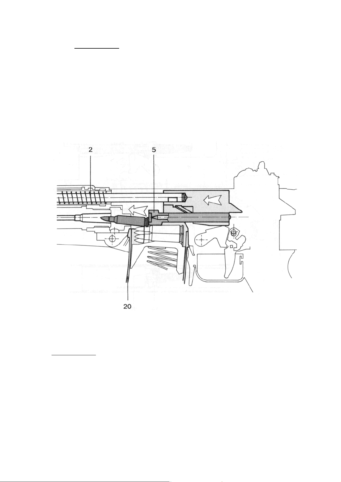
5.1.4. Bolt advance
The force of the compressed recoil spring [2] thrusts the bolt forward.
The bolt head [5] feeds the next round from the magazine [20] into
the chamber.
Bolt advance
52
Page 53
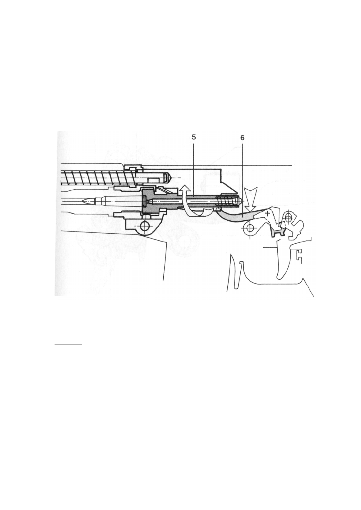
In the final stage of the advance, the bolt head [5] locks up and the
release bar [6] is depressed. The weapon is ready to be fired.
Locking
53
Page 54

6. Appendix
6.1. list of parts
100 receiver
111. Receiver casing
141. Bolt cover
142. Rivet
151. Rear sight drum
152. Drum spring
153. Drum stud
154. Luminous ampoule*
155. Insert
156. Rubber disc
161. Pivot
200 Barrel / gas system
211. Barrel*
212. Front sight mount*
213. Roll pin
214. Spring ring**
221. Bayonet lug**
222. Spring pin
223. Stop pin
224. Compression spring
225. Spring pin
231. Front sight
232. Night front sight
233. Positioning bolt
234. Night front sight spring
300 Handguard
311. Upper handguard
321. Lower handguard
330. Bipod complete**
331. Leg left**
332. Leg right**
400 Bolt
411. Bolt head
412. Firing pin
413. Firing pin stud
414. Firing pin spring
415. Extractor
416. Extractor spring
417. Pin
* Can not be ordered as individual parts
**Not on SG 551
162. Drum axle
163. Spring washer
164. Safety washer
165. Leaf spring
171. Windage correction screw
172. Click stud
173. Rear sight spring
174. Limitation spring
175. Spring pin
181. Elevation correction screw
235. Spring pin
236. Front sight screw
237. Front sight disc
238. Spring pin
241. Gas valve
251. Gas tube
261. Gas piston
262. Recoil spring
263. Spring pin
264. Spring pin
265. Spacer
268. Support washer
333. Bipod carrier**
334. Stud**
335. Circlip**
336. Click stud**
337. Bipod spring**
421. Bolt carrier
422. Bolt handle catch
423. Axel of bolt handle catch
424. Spring of bolt handle catch
425. Bolt handle
54
Page 55

500 Trigger assembly
501. Trigger casing
521. Magazine catch
522. Magazine catch spring
523. Magazine catch pin
524. Bush
541. Pistol grip
542. Floorplate
543. Allen screw
544. Stop nut
545. Nameplate
551. Pressure point screw
552. Stop nut
553. Pressure point spring
554. Trigger guard
555. Trigger guard bearing
561. Hammer
562. Hammer axle
563. Main spring
564. Bolt catch
565. Bolt catch spring
566. Spring bolt
571. Safety lever
572. Safety shaft
573. Locking spring
576. Spring pin
578. Stop ring
581. Trigger
582. Trigger spring
583. Trigger rod
584. Pivot trigger
585. Trigger bush
586. Trigger rod spring
591. Trigger casing stud
592. Spring –pressure pin
593. Spring for trigger casing stud
594. Spring pin
595. Pin
596. Cup spring
600 Butt
611. Buttstock
612. Butt catch
613. Butt catch spring
614. Clip
615. Spring pin
616. Butt
700 Magazine
711. Magazine casing
712. Magazine floorplate
713. Floorplate catch
714. Feeder
715. Magazine spring
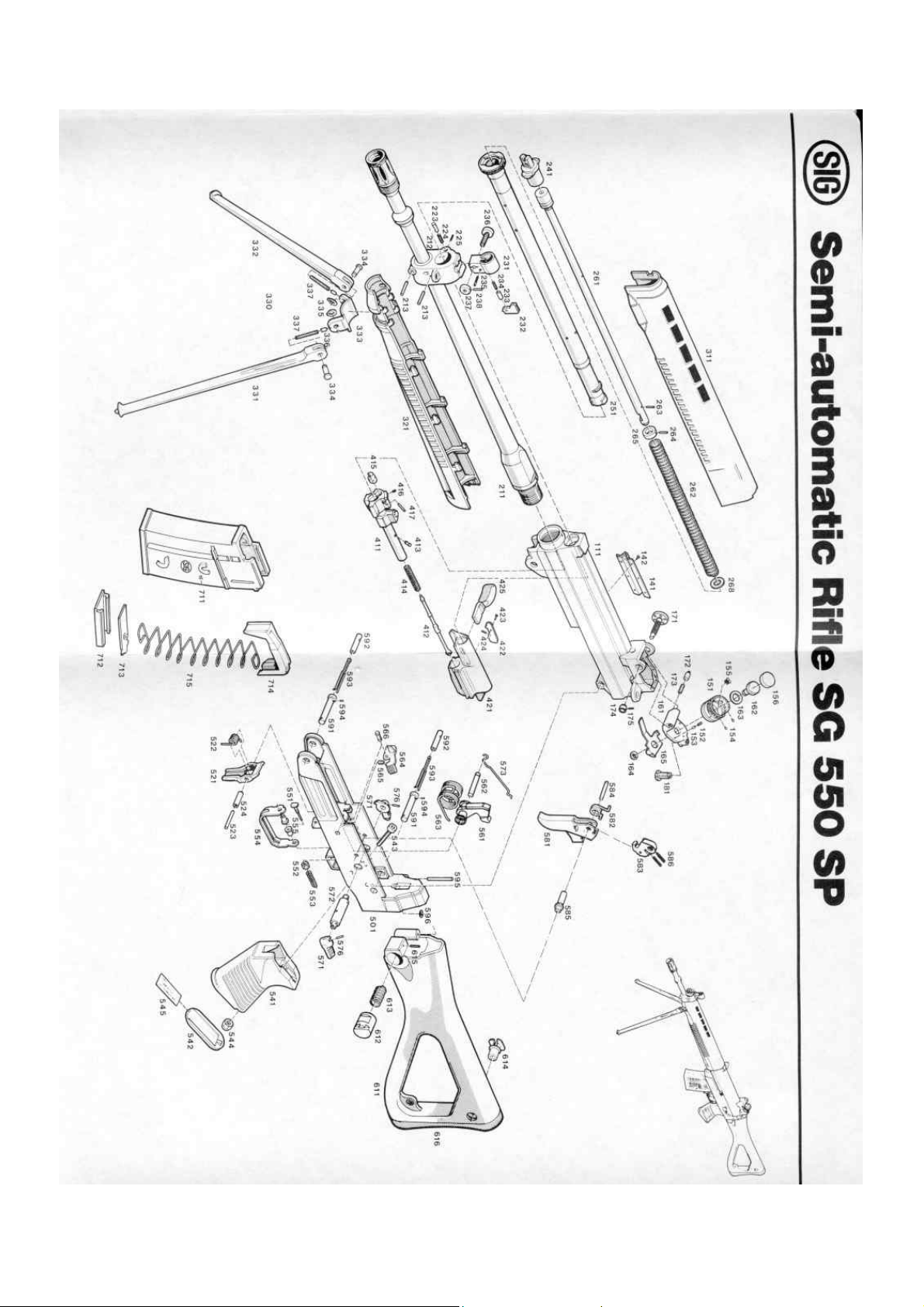
6.2. Exploded drawing
Information to be supplied when ordering spare parts:
Type of weapon
Serial number
Caliber
Item number
Parts designation
55
Page 56
56
 Loading...