


Sig Mfg. Co., Inc....401
-
7 South Front Street....Montezuma, Iowa 50171
Introduction
footed. However, once the bond has been broken between plane and pond, the SEALANE roars to life with a performance not to
winds. It's the perfect choice for your first seaplane adventure. And although the SEALANE is no landlubber, there is an optional
fixed landing gear design for adventures off water down at the local field.
responsibility. If you are new to the sport/hobby of radio control, we urge you to
assembly step or sequence,
do not
guess
- find qualified help and use it.
Radio Equipment
channel radio system and four standard servos. We have used and can highly recommend
used but you will not need any additional radio accessories.
The SEALANE takes off and lands on water just as easy as the Sig Kadet LT40 does on solid ground. Gentle, graceful, sure
be missed. Loops, rolls, inverted flight; all at your fingertips. Water handling characteristics are very positive, even in cross
This assembly manual has been specifically sequenced to get your SEALANE assembled and into the air very quickly. We
strongly suggest that you read through the manual first to get familiar with the various parts and their assembly sequences. The
proper assembly and flying of this aircraft is your
seek the assistance of a qualified person to help you assemble this model airplane. If you do not understand a particular
The SEALANE requires a standard 4both the Hitec™ and Airtronics™ systems. Both of these very affordable and reliable radio systems offer all the features you’ll
need for this and the many other R/C aircraft in your future. For reference, this assembly manual shows the installation of a
Hitec™ radio system with standard servos. The standard 6" aileron servo extension that comes with the radio system will be

.
Engine Selection
Covering Material And Waterproofing
will be almost waterproof.
were made with relatively tight fitting wings, with no additional sealing, and very little water was able to enter the fuselage.
Required Tools
Engine choices for the SEALANE are many. The SEALANE has been designed to produce excellent performance when using
the recommended engine sizes. Do not use an engine larger than recommended.
2-stroke engines are a perfect choice to power your SEALANE. Any plain-bearing or
bearing equipped .40 to .45 sport engine would be a good choice. For example, a
great choice would be the Irvine .40 engine. Like all Irvine engines, the .40 is
powerful, reliable, and quiet. Whatever engine you choose, take the time to carefully
break it in according to the manufacturer’s instructions. A good running, reliable
engine is a minimum requirement for the enjoyment of this or any R/C model aircraft.
The SEALANE can also use a variety of 4-stroke engines. Any 4-stroke engine in
the .40 - .50 displacement range should provide plenty of power. An important thing to
remember is that typical 4-stroke engines have their throttle arms usually located
differently than throttle arms on 2-stroke engines. If you want to power this model with
a 4-stroke engine, you will likely have to install a new, relocated throttle cable tube. While this is not difficult, it is something to
consider when choosing an engine.
Your SEALANE has been designed to be completely covered with any of the popular plastic iron on covering materials on the
market. These covering materials are waterproof and by carefully overlapping the seams approximately 3/32", your SEALANE
The only place on the model where water can enter the fuselage is at the joint where the wing attaches. Our prototype models
A selection of glues: A selection of hand tools, such as:
Sig Thin CA
Sig Medium CA
Sig thin CA applicator tips
Sig Kwik-Shot Accelerator
Sig Epoxy Glue (15 Minute
Working Time)
Regular size and miniature
screwdrivers
Regular size and miniature
pliers
Tweezers or small hemostats
Hobby knife with several new
#11 blades
Sandpaper-assorted grits
Sig Modelers “T” pins
Drill Motor
1/16” Drill Bit
3/16” Drill Bit
1/4” Drill Bit
Covering Iron
Wax Paper
Fuel Proof Paint
Small Paint Brush
Razor saw or
Hacksaw blade
Pencil
Small 90° Square
Masking tape and
Rubber bands
COMPLETE KIT PARTS LIST
Laser Cut Parts
There are 13 Laser Cut Sheets included in this kit. Use the illustrations on the following pages to identify these parts.
Wooden Parts
Qty Assembly Name Size & Material Qty Assembly Name Size & Material
1 Fuselage Fuse Nose Top
Stringer
28 Fuselage Fuse Bottom Sheet 3/32”x3”x3” Balsa Sheet 1 Fuselage Windshield Top Block 1”x1”x4-1/2” Balsa Block
1 Fuselage Nose Block 4”x2-3/4”x3” Balsa Block 1 Fuselage Windshield Top Sheet 3/32”x1-3/4”x4-1/2” Balsa
1 Fuselage Fuse Aft Bottom
Block
2 Fuselage Servo Tray Support 1/4”x1/4”x5-1/4” Balsa Stick 1 Fuselage Switch Wire Guide 1/4”x1/4”x1” Spruce Stick
4 Wing Main Wing Spars 1/4”x1/4”x30” Spruce 2 Wing Trailing Edges 1/4”x1/4”x30” Balsa Stick
4 Wing Trailing Edge Sheet 3/32”x1”x30” Balsa Sheet 2 Wing Leading Edges 3/8”x3/8”x27” Balsa Stick
2 Wing Leading Edge Sheet 3/32”x3”x30” Balsa Sheet 2 Wing Leading Edge Sheet 3/32”x3 1/8”x30” Balsa Sheet
8 Wing Center Section
Sheet
2 Wing Wing Tip 1-1/2”x1-1/2”x11-1/2” Balsa
1/4”x1/4”x13” Balsa Stick 2 Fuselage Fuse Nose Top Sheet 3/32”x3”x13” Balsa Sheet
Sheet
1/4”x2-1/2”x6” Balsa Sheet 2 Fuselage Bolt Block & Firewall
Reinf
3/32”x3”x12” Balsa Sheet 4 Wing Cap Strip Material 3/32”x1/4”x36” Balsa Stick
4 Wing Tip Float Anchor 1/2”x15/16”x1.15” Hardwood
Triangle
1/4”x1/4”x7” Balsa Triangle

.
2 Rolls Iron On Covering + Trim
Wooden Parts
Qty Assembly Name Size & Material Qty Assembly Name Size & Material
2 Wing Wing Dowel 1/4"x1" Birch Dowel 2 Wing Wing Bolt Plate 1/32"x3/4"x1-1/4" Birch Ply
2 Wing Aileron 440”x1-1/2”x25” Balsa
4 Wing Servo Rails 1/4”x1/4”x1-1/4” Spruce Stick 18 Wing Shear Webs 3/32”x2-7/8”x1-5/32” Balsa
2 Tip Float Tip Float Leading
Edge
12 Tip Float Tip Float Sheet 1/16”x3”x7” Balsa Sheet 3 Pylon Pylon Sheet 3/32”x3”x5” Balsa Sheet
1 Pylon Pylon Tail Block 4”x3-1/4”x4-3/4” Balsa Block 3 Pylon Pylon Engine Fairing
1 Tail Surfaces Fin Gussets 1/4”x1/4”x12” Balsa Triangle 1 Tail Surfaces Tail Surface
2 Tail Surfaces Tail Surface
Framework
1 Tail Surfaces Tail Surface
Framework
Trailing Edge
1/4”x1-3/4”x4-3/4” Balsa
Sheet
1/4”x1/2”x36” Balsa Stick 1 Tail Surfaces Tail Surface
1/4”x1”x9” Balsa Stick 1 Tail Surfaces Tail Surface
Continued
2 Wing Torque Rod Bearing
Block
2 Tip Float Tip Float Trailing
Edge
Sheet
Framework
Framework
Framework
440”x1-1/2”x3-29/32” Balsa
Trailing Edge
Sheet
1/4”x1/4”x6” Balsa Stick
1/4”x3”x4-3/4” Balsa Sheet
1/4”x1/4”x4” Balsa Stick.
1/4”x3/4”x36” Balsa Stick
1/4”x1-1/4”x21-3/4” Balsa
Stick
Hardware
Qty Assembly Name Size & Material Qty Assembly Name Size & Material
4 Tip Float Tip Float Attach 8-32 x1-1/2” Pan Head Nylon
1 Wing Strip Aileron Horn
5 Wing,
Fuselage &
Pod
16 Wing & Tail
Surfaces
2 Fuselage Pushrod 24” Nylon Pushrod 2 Fuselage Pushrod End - Elev.
2 Fuselage Pushrod End - @
2 Tail Surfaces Nylon Control
2 Wing Wing Attach Bolts 1/4-20 x1-1/2” Pan Head
1 Pylon Pushrod Connector
1 Pylon Pushrod Connector
1 Pylon Throttle Pushrod
Set
Clevis Nylon 2-56 R/C Link 4 Wing &
Hinge Sig Easy Hinge 2 Fuselage Pushrod Housings 24” Nylon Pushrod Housing
Servos
Horns
Body
Retainer
Housing
Screw
Left & Right Torque Rods with
Connectors
2-56 pushrod 1-1/2” long 1 Tail Surfaces Elevator Joiner Bent 3/32” Music Wire
Sig Medium Control Horns - 1
Left & 1 Right
Nylon Screw
Brass Pushrod Connector Body 1 Pylon Pushrod Connector
Molded Nylon Retainer 1 Pylon Threaded Brass
Pushrod Housing 18” 1 Pylon Throttle Pushrod
4 Tip Float Tip Float Attach 8-32 Blind Nut
2 Wing Aileron Pushrod 2-56 Pushrod 3” Long
Fuselage
4 Tail Surfaces Control Horns
1 Fuselage Switch Pushrod 3/64”x5” Music Wire
Clevis 2-56 Solder Link
2-56 pushrod 7” long
& Rud
#2 x1/2” Sheet Metal Screw.
Screws
4-40 x1/8” Socket Head Screw
Screw
2-56 Brass Coupler
Coupler
Pushrod Cable 18”
Cable
Misc. Parts
Qty Assembly Name Size & Material Qty Assembly Name Size & Material
1 Misc Decal Sheet 1 Color Mylar Decal 1 Misc Fuselage Plan 36”x48” Plan sheet A
1 Misc Wing Plan 36”x48” Plan sheet B 1 Misc Instruction Manual Instruction Manual
1 Misc Windshield .015”x4”x8-1/2” Clear Plastic
Additional Items (Not included in Kit)
Qty Assembly Name Size & Material Qty Assembly Name Size & Material
1 Pylon Motor Mount Dave Brown Mount to Fit
Engine Used
8 Pylon Washers 6-32 Washer 4 Pylon Blind Nuts 6-32 Blind Nut
1 Pylon Fuel Tank Sullivan 8 oz. Round Fuel Tank 1 Pylon Spinner Sig 2-1/4” Spinner
1 Pylon Fuel Line Sig Medium Fuel Line 2 All Covering
1 Pylon Propeller To Fit Engine Used 1 Pylon Engine .40 to .46 2-cycle or .40 to .50
1 All Radio 4-Channel Radio with 4
Standard Servos
8 Pylon Mounting Bolts 6-32 x3/4” Socket Head Cap
Screws
Color
4-cycle
2 Fuselage Radio Protection 3/8”x3”x8” Foam Rubber
Optional Landing Gear Parts (Not included in Kit)
Qty Assembly Name Size & Material Qty Assembly Name Size & Material
2 Main Landing
Gear
Main Wheels 3” Wheels 4 Main Landing
Gear
Wheel Collars 5/32” Wheel Collars

.
Optional Landing Gear Parts (Not included in Kit)
Qty Assembly Name Size & Material Qty Assembly Name Size & Material
4 Main Landing Gear Wheel Collars 3/16" Wheel Collars 1 Main Landing Gear Mounting 1/8" Lite Plywood
1 Main Landing Gear Copper Wire .016 Soft Copper Wire 4 Main Landing Gear Main Landing Gear Legs 3/16"x12" Music
2 Main Landing Gear Mounting Tubes 3/16” K&S Brass Tube #129 3 Tailwheel Mounting 2-56 x1/2” screws
3 Tailwheel Mounting 2-56 washers 3 Tailwheel Mounting 2-56 nuts
1 Tailwheel Mounting 1/32” Birch Plywood 1 Tailwheel Mounting 1/16” Birch Plywood
1 Tailwheel Tail Wheel 1” Wheel 1 Tailwheel Wheel Collars 1/16” Wheel Collar
1 Tailwheel Axle 1/16”x6” Music Wire
Continued
wire

.

.
General Building Notes
The wings and the tail surfaces are built directly over the plan. You should cover the plan with wax paper to protect it and
to prevent the parts from sticking.
BUILDING THE TAIL SURFACES
wood sizes on the plan, cut and glue in place the remainder of the elevator parts.
plan, cut and glue in place the remainder of the fin parts. Remove the fin from the
Sand the outside edges of the fin and rudder round. Bevel the leading edge of the
edge of the elevators. Mark and drill the
joiner wire. Cut a small channel in the
glue).
Set the stabilizer and elevator assembly aside until needed later in construction.
not built over the plan.
1. The SEALANE is recommended for the modeler who has previous building experience. Although the SEALANE is an
easy model to build and fly, the instructions were written assuming that the builder has previous experience. As such,
procedures such as how to make a proper wood joint or detailed covering instructions are not covered.
2. The first thing that you need to do is mark part numbers on the laser cut parts using the drawings for reference.
3. The laser cut parts have small tabs that keep them attached to the main sheet. You should use your hobby knife to
remove the parts from the sheets. If a part is not completely cut through you can use your hobby knife to free it from the
sheet.
4. The slight discoloration of the edges of the laser cut parts may be removed by lightly sanding them with 320 grit
sandpaper.
5.
1.
Cover the stabilizer and rudder plan with wax paper. Pin stabilizer parts S-1 and
both S-2’s into position on the plan. Using the wood sizes on the plan, cut and
glue in place the remainder of the stabilizer parts. Remove the stabilizer from the
plan.
2.
Pin and glue elevator parts S-3, S-4, and S-5 into position on the plan. Using the
Remove the elevator from the plan.
3.
Pin fin parts R-1 and R-2 into position on the plan. Using the wood sizes on the
plan.
4.
Pin rudder parts R-4 into position on the plan. Using the wood sizes on the plan,
cut and glue in place the remainder of the rudder parts. Remove the rudder from
the plan.
5.
rudder. Mark the hinge locations, cut the slots, and temporarily install the hinges
(without glue). Set the fin and rudder assembly aside until needed later in
construction.
6.
Sand the outside edges of the stabilizer
and elevators round. Bevel the leading
holes in the elevators for the 3/32"
leading edge just inboard of the holes
for the joiner to fit into, allowing it to be
flush with the leading edge. Mark the
hinge locations, cut the slots, and
temporarily install the hinges (without
BUILDING THE FUSELAGE
NOTE: The fuselage is built mostly from laser cut lite plywood parts. You will use the plan as a guide but the fuselage is

.
7.
Glue the fuselage doublers (F
-
2) to the inside of the fuselage sides (F
-
1). Be sure that you make a left and a right side.
that the front of the fuselage is not twisted and glue the formers into position.
pivoting the back end down into position and glue in place.
into position.
glue to bond the rear of the fuselage together.
7 and F
-
10.
off flush with the front of F
-
7 and the rear of F
-
17.
8.
Glue formers F-3 and F-5 into position on the right fuselage side. Use a small square to make sure that the formers are 90°
to the fuselage side.
9.
Place the left fuselage side into position on the formers and glue in place.
10. Glue formers F-4A and F-4B together as shown on the plan. Now slide the formers into position in the fuselage and glue in
place. Gently squeeze the fuselage together at the front and place formers F-6 and F-7 into position. Carefully check to see
11. Glue formers F-15A and F-15B together as shown on the plan. Now slide F-15 into position in the fuselage and glue in
place. Place F-8 into position on the fuselage. Do this by sliding the tab in the front of F-8 into the notch in F-7 and then
12. Squeeze the back end of the fuselage together and hold with clothespins or small clamps. Tack glue formers F-9 and F-10
13. The rearmost end of the fuselage should be 90° to the fuselage top. Loosen the clamps and adjust if required. Now apply
14. Glue the keel (F-14) into the slots in the bottom of the fuselage formers. Align the step in the keel with formers F-4A and F-
4B. The keel may extend slightly past F-7 and F-10. When the glue is dry, trim the ends of the keel flush with the formers F-
15. Glue formers F-16, F-17, and F-19 into position. F-16 and F-17 should be centered left and right and 90° to F-8. F-19
should be 90° to F-3. Glue the 1/4” sq. balsa strip between formers F-7 and F-17. When the glue is dry, trim the balsa strip

.
Take one of the 3/32" top front balsa sheets and place into position on the fuselage as shown. The lower edge should touch
Airplane Cleaner. Allow it to soak in for about 10 minutes.
NOTE: Depending on the grain and hardness of the sheet, you might find that several small splits open up in the lower edge
top sheeting into place. When the glue is
16. Position the wing bolt blocks (F-18) in the fuselage assembly. The top edge
should be 1/4" below the top edge of the fuselage side to make room for the 1/4”
balsa triangle reinforcements. Glue the bolt blocks in place with epoxy. Cut the
1/4" balsa triangle reinforcements and glue into position.
17. Sand the front edge of F-11 so that it is flush with the front of F-12. Sand the
proper angle on the bottom of F-20 and glue it into position on the front of F-12.
When the glue is dry, trim the top edge of F-20 flush with the top of F-11.
18.
the fuselage side and the other edge should stick up at an angle. When the sheet is positioned properly you can glue it to
the fuselage.
When the glue is dry, thoroughly wet the outside of the sheet with an ammonia based cleaner such as Sig’s Pure Magic
19. Using the palms of both hands, carefully bend and roll the sheet around the formers. Hold the sheet in position and mark
and trim the inboard edge to the centerline of the 1/4" sq. balsa strip. Now glue the sheet into place.
as you are rolling the sheet into place. This is not a problem. After the sheet is installed, apply a small amount of thin C/A to
the cracks and then fill them in with balsa filler such as Hobbico Hobbylite™ Filler and sand smooth.
20. Now fit, trim, and glue the opposite side
dry, trim and sand the front and rear
edges flush with F-7 and F-17.
21. Using a gentle fore and aft motion,
carefully sand the fuselage bottom so
that the sides and keel match the angle
of the formers.
22. Working from F-4 forward, glue the
bottom sheet pieces into position. The
inboard edge should be centered on the
keel (F-14) and the outboard edge
should extend past the fuselage side.
The first four pieces should fit into
position with out trimming the inboard
edge. Because of the curvature of the
nose of the model, the inboard edge will
need to be trimmed to the center of the
keel.

.
balsa sheet to the bottom of the fuselage
and sand the bottom sheet flush with the
sheet.
Glue the nose block into position on the front of the fuselage. When the glue is dry, carve and sand the nose block to shape
Now trim the block to this outline. The outline should be slightly oversized.
Now sand the fuselage smooth all over.
23. Working rearward from F-4 toward F-10,
glue the bottom sheet pieces into
position. The inboard edge should be
centered on the keel (F-14) and the
outboard edge should extend past the
fuselage side. Glue the 1/4"x2-1/2"x6"
behind F-10. When the glue is dry, trim,
fuselage sides.
Continue the "V" shape of the bottom all the way back to the aft end of the model by sanding the bottom of the rear 1/4"
24.
using the following steps. The first thing to do to shape the nose block is to draw the side profile onto the block as shown.
25. Now draw the top profile onto the block
as shown. Now trim the block to this
outline. The outline should be slightly
over size.
26. Sand the bottom of the block with a fore
and aft motion to match the angle of the
"V" on the bottom of the fuselage. You
can draw a centerline on the block to
assist you.
Finally, sand the top corners round and smooth the block all over.

.
BUILDING THE WING
panels.
Also, pin the 1/4" sq. balsa trailing edge to the plan. The inboard ends should be
4 rib
at the wing tip.
spar and trailing edge. Glue the W
-
4 rib against the outboard side of W
-
1.
inboard. Use the front view on the plan to help identify the proper alignment.
the shear webs with the top spar notch before gluing.
should be oriented the same as the W
-
2 shear webs.
cuts.
2’s. Place the 3/32"x1" trailing edge sheet into position and glue it to the top of the 1/4" sq. trailing edge and the wing ribs.
against the wing ribs. The shear webs should be glued to the spars as well as the wing ribs.
NOTE: The wing is built directly on the plan, so cover the plan with wax paper
before assembly. These instructions are identical for both the right and left wing
27. Start building the right wing by pinning the lower 1/4" sq. spruce spar to the plan.
located as shown in the photo. The outboard ends will extend past the last W-
28. Place rib W-1 into position. It should be 90° to the building board. Glue W-1 to the
29. Place the two laser cut lite ply shear webs (W-2) into position. Use a scrap of 1/4" balsa from one of the laser cut sheets as
a spacer to maintain proper separation between the F-2’s. Glue the F-2’s to the main wing spar and to rib F-1.
IMPORTANT NOTE: One end of W-2 is 90° and the other end has a slight angle. The end with the angle should face
30. Place rib W-3 into position. Because of the angle on the inboard end of W-2, the W-3 will not be 90° to the building board
but instead it will lean slightly toward the wing tip. Glue the rib to the main spar and to the W-2 shear webs. Be sure to align
31. Place parts W-5 and W-6 into position between W-1 and W-3. Note that there is an angle on one end of these parts which
32. Carefully cut the spar joiner slots in ribs W-1 and W-3 as shown. You can use your hobby knife or razor saw to make these
33. Position the remaining W-4 ribs on the spar and trailing edge and glue in place. These ribs should be 90° to the building
board.
34. Place the top 1/4" sq. main spar into position with the inboard end flush with the face of the W-3 rib. Make sure the spar is
completely seated in the slots in the ribs and glue the spar in place. The inboard end should be flush with the top of the W-
35. Glue the 3/32" balsa shear webs to the back of the main spars in the second and third rib bay as shown. These shear webs
have the grain oriented vertically. The parts provided in the kit are slightly long and should be trimmed to achieve a tight fit

.
Glue the 3/8" sq. balsa leading edge into position at the front of the wing ribs.
sheets are used on the top of the wing. The 3" sheets are used on the bottom of the wing only.
1/8" wide 3/32" leading edge sheet into position as shown. The front edge should be completely against the 3/8"
When positioned properly, the sheet should be glued to the 3/8" sq. leading edge only.
Glue the 3/32" wing center section sheet
wing between the leading and trailing
edge sheet. When properly fit, glue W
-
8 into place.
36. Glue the 3/32" balsa shear webs to the front of the main spars in the second through the eight rib bay as shown. These
shear webs have the grain oriented vertically. The parts provided in the kit are slightly long and should be trimmed to
achieve a tight fit against the wing ribs. The shear webs should be glued to the spars as well as the wing ribs.
37. Glue the hardwood tip float anchors (W-7) to the spars and the wing rib at the location shown on the plan.
NOTE: There are four pieces of 3/32" balsa sheet in the kit for sheeting the leading edges of the wing. The 3-1/8" wide
38. Place the 3-
sq. leading edge and the ends should extend past the W-3 rib at the inboard end and the W-4 rib at the outboard end.
39. Roll the sheeting back and down onto the wing ribs. Glue the sheet to all of the wing ribs and to the top spruce spar.
Note: You can moisten the outside face of this sheet with an ammonia based cleaner such as Sig’s Pure Magic Airplane
Cleaner. Allow it to soak in for about 10 minutes before bending the sheet.
40.
into position at the inboard end of the
edge sheet. The outboard end should
end at the point shown on the plan with
the extra length extending past rib W-3.
The front piece can be used with it’s full
3" width. The second (rear) sheet needs
to be trimmed to the proper width to fit
between the first sheet and the trailing
edge sheet.
41. Fit the tip float rib cap strip (W-8) into position at the location shown on the plan. Trim the rear end to fit against the trailing
42. Remove the wing from the plan. From the bottom, and using the W-7’s as a drill guide, use a 5/32" drill bit to drill through
the tip float rib cap strip (W-8). After drilling the two holes, place the wing panel back onto the building board.
Cut the remaining top cap strips from the 3/32"x1/4" balsa strip and glue them into position onto each exposed rib.

.
the 3/8" sq. leading edge only.
Cleaner. Allow it to soak in for about 10 minutes before bending the sheet.
first sheet and the trailing edge sheet.
with both ends of the wing as shown.
wing with the excess sticking up above
43. Turn the wing panel over, upside down on the building board. Place the 3" wide 3/32" bottom leading edge sheet into
position as shown. The front edge should be completely against the 3/8" sq. leading edge and the ends should extend past
the W-3 rib at the inboard end and the W-4 rib at the outboard end. When positioned properly, the sheet should be glued to
44. Roll the sheeting back and down onto the wing ribs. Glue the sheet to all of the wing ribs and to the top spruce spar.
Note: You can moisten the outside face of this sheet with an ammonia based cleaner such as Sig’s Pure Magic Airplane
45. Glue the 3/32" wing center section sheet into position at the inboard end of the wing between the leading and trailing edge
sheet. The outboard end should end at the point shown on the plan with the extra length extending past rib W-3. The front
piece can be used with it’s full 3" width. The second (rear) sheet needs to be trimmed to the proper width to fit between the
46. Fit the tip float rib cap strip (W-8) into
position at the location shown on the
plan. Trim the rear end to fit against the
trailing edge sheet. When properly fit,
glue W-8 into place. Cut the remaining
cap strips from the 3/32"x1/4" balsa strip
and glue into position.
47. Trim the wing sheeting and spars flush
Sand the leading edge uniformly round.
Sand the wing panel smooth all over.
48. Glue the lite ply tip ribs (W-9) to the
outboard end of the wing.
49. Glue the triangular wing tip block into
position as shown. The bottom edge
should be flush with the bottom of the
the top of the wing.
50. Trim the top of the wing tip block to match the airfoil shape of the top of the wing ribs and W-9. Then sand the front end
round to match the wing leading edge.

.
and this part of W
-
10 is easier to remove at this time.
joiner into the slot in the left wing. Wipe any excess epoxy that squeezes out of the joint and allow to dry completely.
Use 30 minute epoxy to glue the wing joiner into the right wing and to join the right
wing to W
Using the plan as a guide, mark the location of the aileron torque rod assembly on
Now glue the torque rod blocks to the trailing edge of the wing.
Place the wing back onto the fuselage. Use the centerline marks to establish the proper alignment of the trailing edge. Mark
approximately centered on the plywood wing bolt blocks in the fuselage.
51. Use epoxy to glue W-10 to the face of W-1. The bottom should be flush with the bottom of the wing and the front should be
flush with the front of W-6. Be sure that the pointed part is not blocking the hole between the spars.
52. Use a razor saw or a hack saw to cut away the section of W-10 as shown in the photo. This is the area for the aileron servo
53. Without using glue, test fit the 1/4" birch ply wing joiner into both the left and right wing panels. You may lightly sand these
parts if the fit is too tight, however you do want a snug fit without slop or play. Now, using 30 minute epoxy, glue the wing
54.
-10.
55.
the bottoms of the two torque rod bearing blocks. Cut a small notch in the lower
leading edge for clearance. Be sure to make a right and left hand parts. Lightly oil
the wire to help prevent excess glue from sticking.
Carefully glue the aileron torque rods into the blocks by applying a tiny amount of
glue to the brass tube bearing and pressing the torque rod into position.
56. Place the wing on the fuselage. Mark a centerline on the fuselage and the wing.
Use these marks to align the wing on the fuselage. It must be centered left and
right. Now hold the wing tightly in position and use a 1/4" drill bit to drill the wing
dowel holes in W-6 & W-5.
57. Use epoxy to glue the 1/4" dowels into the front face of the wing center section.
Be sure that the dowels are pointed straight ahead and not angled to the side or
up and down. Allow the epoxy to cure.
58.
the location of the wing bolts on the top of the wing. The approximate location of the holes is 5/8" forward of the trailing
edge and 3/4" in from the fuselage side. Double check the measurements on your model to ensure that the holes will be
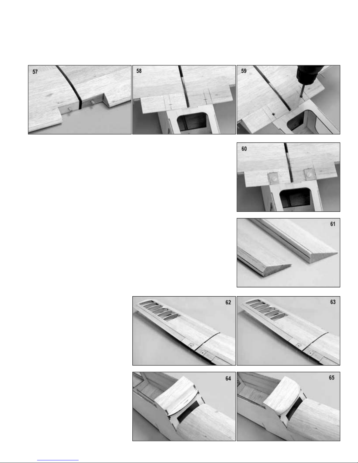
.
threads with thin C/A glue to harden the wood. When dry, run the tap back through the holes to clean out the threads.
Trim or sand the bevel on the front of the two ailerons. Mark guidelines on the top,
away down to the guide lines. Lightly sand as required to finish the bevel. Hold the
ailerons against the wing trailing edge and cut it to the proper length. There should
rod wire and allow the aileron to be flush against the trailing edge of the wing. Test
amount of overhang all around. After the
59. Hold the wing securely in position on the fuselage and drill 3/16" holes through the wing and into the wing bolt blocks in the
fuselage. The drill should be held so that it is angled 90° to the top of the wing surface.
Remove the wing from the model. Use a 1/4-20 tap to cut threads in the wing bolt blocks. After removing the tap, coat the
60. Glue the 1/32" plywood wing bolt plates to the top of the wing. They should be
centered on the 3/16" holes in the wing. Now use a 1/4" drill bit to open up the
3/16" holes in the wing and drill through the wing bolt plates. Use the nylon 1/4-20
x1-1/2" bolts to mount the wing back into position on the fuselage.
61.
front, and bottom of the aileron. Now use your hobby knife to trim the corners
be a 1/16" gap at each end. Also mark the location of the hinges and the aileron
torque rod.
62. Cut the slots for the hinges in the wing and ailerons. Drill a 3/32" hole in the
leading edge for the aileron torque rod. You will also need to cut a small pocket in
the leading edge from the torque rod hole to the inboard end to accept the torque
hinge the aileron to the wing and make sure that the ailerons move freely.
You will need to cut a small angled notch in the bottom of the wing immediately in
front and in back of the aileron torque rod to allow it to move forward and
backwards, where it exits the bottom of the wing.
63. Sand the wing entirely smooth and set
aside for now.
64. Glue the 3/32" balsa sheet to the top of
the fuselage between F-3 and F-15.
Note that the grain runs left and right.
Position the sheet so there is an equal
glue is dry, trim away the excess sheet
and sand it flush on all sides.
65. Glue the 1" sq. x4-1/2" balsa block into
position on top of F-9 and against F-3.
When the glue is dry, trim and sand the
block to the shape shown here and on
the plan.

.
BUILDING THE MOTOR PYLON
Install the mount on the firewall with the proper screws. If the screws extend past the rear of the firewall they must be cut off
Assemble the motor pod from parts P
Assemble the fuel tank following the
and insert the fuel tank into the pod. The
front of the tank should be up against the
and rear edges round. The top and bottom should not be sanded. Test fit the support to the bottom of the pod.
66. Place the motor mount that you are using on the firewall (P-2). Center the hole in the mount with the hole in P-2. Mark and
drill the mounting holes in P-2. Remove the mount from the firewall and install the 6-32 blind nuts.
to prevent damage to the fuel tank. The motor mount screws should stick out the back of the blind nuts about 3/32".
Position the motor on the mount. The front face of the propeller flange on the motor should be 3/34" to 4" forward of the
firewall. Mark and drill the motor mount for the screws that you are using. Temporarily bolt the motor to the mount. Check
the fit and security and then remove the motor from the mount.
67.
P-2, P-3, and P-4. Use epoxy and make
sure that all of the joints are securely
glued. Double check that the blind nuts
on the firewall are facing the proper
direction. Glue the two pieces of 1/4"
balsa triangle into the front corners
between P-2 and P-4 sides.
-1,
68.
manufacturers instructions. Use a two
line system where one line is the fuel
pickup/fill line and one line is the
pressure/vent line. Place a bead of
silicone rubber to the front of the tank
back of the firewall and the silicone
should seal and bond the tank to the
firewall. Allow the silicone to dry.
69. Glue the two pylon support parts P-6 to each side of P-5. When the glue is dry, trim away any overhang and sand the front

.
block to the cylindrical shape as the pod.
corners. Use care not to bend or kink the
throttle pushrod where it exits the bottom
well as the motor bolts.
70. Mark the firewall for the location of the throttle pushrod. Mark the bottom of the
pod where the throttle cable will exit. Now carefully drill holes in these parts
making sure that you do not damage the fuel tank.Insert the throttle pushrod
housing into the pod with about 2" sticking out of the firewall and the remainder
sticking out from the bottom of P-1. Glue the housing securely into position.
71. Wrap and glue the 3/32" sheeting around the pod. When the glue is dry, trim the
sheet flush with the front of P-2 and the rear face of P-3.
72. Glue the balsa block to P-3. The bottom of the block should be flush with the bottom of P-1. When the glue is dry, sand the
73.
Trim and sand the rounded side profile,
the top profile and finally round off the
of the pod.
74. Bolt the motor back on the motor mount. Slide the spinner backup ring (P-7) over
the crankshaft. Install the spinner back plate on the motor using the proper
adapter and the motors thrust washer and prop nut. If the threads on the
crankshaft are not long enough to allow the nut to be tightened without the
propeller, use spacers behind the nut as required.
Glue several small scraps of 3/32" balsa between the spinner back plate and P-7.
This will establish an even spacing between these parts.
75. Cut the bottom piece of the motor fairing from one of the 1/4" balsa sheets
provided. The back end should beveled to create a tight fitting joint against P-1.
The front edge should be beveled to create a tight fit against P-7. When you are
satisfied with the fit, glue the 1/4" balsa sheet into position.
76. Cut, fit and install the remaining 1/4" balsa sheet sides of the fairing. Start at the
bottom and work toward the top. The pieces of sheet should be trimmed to
achieve a tight fit against the adjacent parts. Build up the sides to the level shown
in the photo. When the glue is dry, trim the top edges to allow clearance for the
muffler and needle valve and also to provide access to the fuel and vent lines as

.
until it is time to cover the model.
servo as shown. Remove the servo and
the aileron servo well.
Test fit the servo in the opening. There should be about 1/16" clearance between the servo case and the lower wing skin.
BUILDING THE FLOATS
wing.
4 parts on the bottom of the
wing. Align the centerlines on the T
with the marks on the wing and tape T
4
wing and through T
s and test fit them
77. Remove the engine from the mount.
Trim and sand the fairing to a smooth
shape. Drill a 1/4" drain hole in the
bottom of the fairing. This drain hole
should be centered left and right and
immediately in front of the firewall (P-2).
Remove the motor mount from the
firewall.
The firewall and exposed wood inside the fairing should be painted and sealed with a fuel proof paint such as Sig Butyrate
Dope or epoxy.
Test fit the motor pylon assembly to the wing. The supports should be a tight fit into the slot in the wing. Drill a 1/16" hole
through the wing to allow the throttle pushrod housing to pass through. Now remove the pylon parts and set them aside
78. Just before joining the wings, you cut
away a section of W-10. Take one of
the servos and set it on the bottom of
the wing. Center it fore and aft over the
cut out section of W-10. The servo
should be centered left and right. Use a
pen to mark around the base of the
use your hobby knife to remove the
balsa sheet on the bottom to open up
79.
Lay the parts T-4 over the drawing on
the plan. Mark both fore and aft and left
and right centerlines on these parts as
shown. Mark fore and aft and left and
right centerlines on the bottom of the
80. Place the T-
-4’s
securely to the bottom of the wing. Use
a 5/32" drill bit to drill down through the
-4. Mark the T-4
parts "left" or "right". Install the 8-32
blind nuts into the T-4’
by bolting them to the wing.
Make sure that the centerlines stay
aligned while drilling the holes.

.
1 as
1. When
and both sides of the other tip float.
s and the fuselage to allow for the thickness of the covering. Sand
the parts smooth to match the contour of the leading edge.
BUILDING THE OPTIONAL LANDING GEAR MOUNTS
gear actually can be added to the model after it is completely finished. If you decide not to add it at this time but decide later
Note: The parts for the optional material are not included in the kit and must be supplied by the builder.
wooden landing gear parts.
81. Glue the parts T-2, T-3 and T-4 to Tshown. They should be 90° to Tthe glue is dry, sand the front of the
assembly so the front of the formers are
flush with T-1.
82. Test fit and glue the 1/4” balsa tip float
leading edge into position. The leading
edge should be centered left and right
and from top to bottom.
83. Take the 1/16" balsa tip float sheet and glue them together as shown on the plan. You will need to make 4 sets of sheeting,
two for the left tip float and two for the right tip float. Place the front edge of the sheet against the leading edge sheet and
against the front edge of the formers and glue the sheet to the leading edge. When the glue is dry, roll and press the sheet
into contact with the formers and glue securely into position. Repeat this process to sheet the opposite side of this tip float
84. Trim and sand the sheet flush with the top, bottom and trailing edge of the float. Trim and sand the 1/4" balsa leading edge
to the rounded shape shown. Glue the 1/4" sq. balsa trailing edge to the back of the floats and then sand to match the
contours of the tip float.
85. Mount the wing onto the fuselage. Use the parts W-11 to fill in the gaps between the leading edge of the wing and the
fuselage. There should be a 1/32" gap between the W-11’
If you would like to add the optional landing gear to your model, complete the following steps now. However, the landing
that you want to, it’s not a problem.
86. Use the patterns on the plans to cut the
87. Glue the two F-1C doublers into position
on the inside of the left and right
fuselage sides. The bottom edge should
touch the sheet on the bottom of the
fuselage and the front and back should
touch the formers.

.
1C, drill two 3/16" holes through each fuselage side. Fit and glue the front and rear landing
Lay the 1/16" plywood parts "A" on the bottom of the rudder and mark a line along the top edge of "A". Use your hobby knife
s should be flush with the rudder when properly cut. Glue
s into place making sure that the top is flush and the gap between them is parallel to the rudder centerline. Sand
the plywood parts smooth and round the back end to match the curve on the rudder.
servo tray.
the radio into the servo tray. Unless the switch is extra long, you will not use the normal face plate provided with the switch.
88. Using the locations marked on Fgear support into position as shown on the plan. The top edges should line up with the bottom of the holes in the fuselage
sides. Cut two 4-7/8" lengths of 3/16" brass tube into the holes in the fuselage making sure that the 3/16" wheel collars are
in place. The tubes should stick out from the fuselage sides an equal amount. Glue the tubes to the supports and the
fuselage sides. The wheel collars can be epoxied to the fuselage side with the screw hole at the top. When the epoxy has
cured, sand the excess tube off flush with the fuselage side.
89.
to trim the 1/2" balsa strip from the bottom of the rudder. Use your hobby knife to trim 1/16" of material from the rudder as
shown. Use the parts "A" to measure the depth of the cut. The "A"’
the two "A"’
PRE-COVER ASSEMBLY
90.
Measure and mark a line in the fuselage about 3" down from the edge of the wing opening. Glue the two 1/4" sq. supports
to the fuselage immediately below the line. Now glue the lite ply servo tray (F-21) into the fuselage. The tray should sit on
top of the balsa supports. You might have to squeeze the fuselage sides together to pull them against the edges of the
91. Mount the elevator and rudder servos into the servo tray using the hardware provided with the radio. Mount the switch for

.
with the switch.
hole in it. Some switches come with this
s
Insert the rudder and elevator pushrod housing tubes into the fuselage with about
with sandpaper for better adhesion and glue the pushrod housings into the exit.
movement.
Mount the elevator and rudder servos
into the servo tray using the hardware
provided with the radio. Mount the
switch for the radio into the servo tray.
Unless the switch is extra long, you will
not use the normal face plate provided
The switch lever should have a 1/16"
hole, however some do not and if your’
does not have the hole, you will have to
drill it.
92.
Glue the ventral fin (R-3 to the bottom of the fuselage. Make sure it lines up with
the aft end of the model so that the rudder will fit properly.
1-1/2" sticking out from the exit at the fuselage side. Slightly roughen up this end
When the glue is dry, trim and sand the housings flush with the fuselage sides.
93.
Mark the angle shown on the top of F-
20. Use your hobby knife to trim F-20
back to the marked lines. The angles
should extend from the top to the
bottom of F-20. Now gently sand F-20
smooth.
94. Make a final test fit of the tail surfaces to the fuselage. Pin the stabilizer and elevator to the fuselage. Pin the fin into
position. Cut the lower two hinge slots into the fuselage. Temporarily hinge the rudder to the model and test for proper
95.
Cut the windshield pattern from the plan and test fit it to the fuselage. If all looks well, place the pattern on the windshield
plastic and carefully cut around it with a new sharp knife. Use tape to temporarily hold the windshield into position and trim
if needed for a tight fit.

.
COVERING YOUR MODEL
such as Hobbico Hobbylite™ Filler.
97. Cover the model with one of the plastic iron on coverings available.
as a guide for placement.
FINAL ASSEMBLY
with a felt tip pen. Remove the
windshield from the model and use your
bare wood can be painted (we used Sig
Black Dope) if you would like.
When the glue is dry, finish the edges of
the windshield with trim tape as shown.
model. Carefully align it so that it is level
when viewed from the front and
when viewed from the top. In addition,
Remove the stabilizer from the model and very carefully trim the covering away from the bottom of the stabilizer to produce
wood to wood contact between the stabilizer and the fuselage.
96. Remove the tail surfaces from the model. Sand the entire model smooth. Any gaps or dents can be filled with a balsa filler
98. Carefully trim the markings from the decal sheet and apply them to the model. Use the photos on the box and this manual
99. Use tape to hold the windshield on the
model. Trace around the windshield
hobby knife to remove the covering
from the areas where the windshield
makes contact with the fuselage. The
Glue the windshield to the fuselage.
100. Place the stabilizer into position on the
perpendicular to the fuselage centerline
the slot for the fin in the stabilizer must
line up with the corresponding slot in
the fuselage. Use a felt tip pen to trace
around the fuselage where it contacts
the stabilizer.
DO NOT CUT INTO THE WOOD WHEN REMOVING THE COVERING OR YOU
WILL SEVERELY WEAKEN THE STABILIZER.
Now glue the stabilizer to the fuselage with epoxy to allow time to align it with the
fuselage.
101.
Glue the elevator joiner wire into the elevator halves. Install the hinges in the
elevator and glue to the stabilizer.
Test fit the fin to the top of the stabilizer. Mark and remove the covering where
the fin will contact the stabilizer. Now glue the fin into position making sure that
the fin is properly aligned.
Trim and fit the 1/4" triangle braces at the bottom of the fin. Mark and remove the
covering from the fin and stabilizer under the balsa triangle. Cover the outside
surface of the balsa triangles with covering material. Now glue the braces into
position.
102. Hinge the rudder to the vertical fin and fuselage tailpost. When the glue is dry on
the hinges, flex the rudder and elevators several times to free up the hinges and
to check for proper operation.

.
Assemble the rear ends of the elevator and rudder pushrods, using the 2
nylon clevis onto the reaming pushrod threads.
end pushrods. These are the servo ends
of the rudder and elevator pushrods. Make two of these assemblies, as shown.
Attach the clevis to the output arms on the rudder and elevator servos. Position the elevator and rudder in the neutral
centered.
wire and install. Glue the 1/4" sq. spruce
the wire extension.
movement.
103.
-56 x7" threaded one-end pushrods. Insert the
unthreaded end all the way into nylon tube and thread the pushrod in place, using about 1/2 of the threads. Now thread the
104. Slide the elevator and rudder pushrod into the fuselage from the rear. Use the pushrod and clevis to help establish the
location for the elevator and rudder horn. Drill the mounting holes for the horns in the elevator and rudder and install them
using the screws provided. Move the control surfaces to check for freedom of movement. You may have to bend the rudder
pushrod slightly to prevent binding.
105. Solder a solder clevises onto the unthreaded end of the 2-56 x1-1/2" threaded one-
106.
position. Pull the pushrod housings forward against the sides of the threaded rods and mark the housings at the forward
end of the threads in the rod. Cut the housing and inner pushrod at the mark. Remove the inner pushrod and cut an
additional 1" from the front of the housing. Reinstall the pushrods and screw the front clevis into the pushrods. Attach the
clevis to the servos and adjust the length so that the control surfaces are in the neutral position when the servos are
107. Slip the lite ply pushrod retainers (F-22) into position on the elevator and rudder pushrods. The F-22’s should be glued to
former F-5 and to the pushrod housings.
108. Bend the 3/64" dia. x5" switch extension
retainer to F-21 so that it just touches
109. Hinge and install the ailerons on the
model. Glue the hinges securely and
also glue the torque rod ends into the
ailerons. When the glue is dry, flex the
ailerons up and down to loosen up the
hinges and to check for freedom of
110. Remove the covering at the aileron servo rail locations at each end of the aileron servo and glue the 1/4" spruce servo rails
to the wing. When the glue is dry, mount the servo with the hardware supplied with the radio.

.
bolt the motor & mount into position.
Assemble the throttle servo mount from
when the servo is centered as shown.
connector and slide the servo down onto
111. Thread the nylon torque rod fittings onto
the aileron pushrods. Attach them to the
connectors on the aileron torque rods.
With the ailerons in the neutral position
and the servo centered, mark, cut, and
solder the metal clevisie to the front end
of the pushrods. Attach the pushrods
and adjust the pushrods until the
ailerons are in the neutral position when
the servo is centered.
112. Using 30-minute epoxy, glue the motor pylon support into the slot in the wing center section.
113. Glue the motor pod to the top of the motor pylon support using epoxy. Cut away any covering material on the bottom of the
pod that would prevent a wood to wood joint. When the epoxy is hard, attach the fuel and vent line to the fuel tank and then
114. Take one end of the throttle cable and
bend it back on itself 1/2" as shown.
Now insert this end of the throttle cable
into the threaded brass coupler and
solder securely together. Screw the
small nylon clevis onto the end of the
brass coupler. Feed the throttle cable
into the housing and attach the clevis to
the throttle arm on the motor.
115.
parts TS-1, TS-2, and the two 1/4" sq.
spruce strips. Be sure that the TS-2
ends are 90° to the base (TS-1). When
the glue is dry, install the throttle servo
using the hardware provided with the
radio. The servo arm on the throttle
servo should be positioned fore and aft
116. Install the pushrod connector onto the
output arm on the throttle servo. Insert
the throttle cable into the servo
the wing. Mark around the base of the
throttle mount. Remove the servo and
remove the covering from the wing to
provide a wood to wood glue joint.
Reposition the servo on the wing and
glue into position.

.
When the glue is dry, trim the excess length from the throttle cable. Bend the end
over about 1/2" and insert the end back through the servo connector so there is a
full throw and tighten the screw in the servo connector.
vibration.
on the plan. Insert the front landing gear
wheel collar inside the fuselage to lock
wheels and retain them with wheel
Bend the tailwheel wire to shape. Epoxy
wheel wire sandwiched in the middle.
wheel to the axle. Insert this assembly
Drill the mounting holes and use 2
-
56 screws and nuts to hold the tailwheel assembly in place.
Wrap the airborne battery pack in foam and place it in a small plastic bag for waterproofing. Attach the extension cable that
came with your radio to the battery pack. Insert the battery pack into the fuselage and all the way forward in the nose of the
model. There should be enough foam to wedge the battery in place and hold it from sliding around.
done with the fuel tank empty. Add weight to the nose or tail until the proper balance is achieved.
the sticks on the transmitter.
Always pre
responsibility to verify that your model is airworthy. Always follow established safety guidelines while starting and operating
double thickness of cable passing through the connector. Adjust the throttle for
117. Install the propeller and spinner onto the motor. Install the muffler onto the motor
and connect the feed and vent lines.
NOTE: The pylon feature found on flying boats such as the Sealane are more
sensitive to vibration than a traditional fuselage mounted motor. For this reason it
is important that you balance the propeller / spinner assembly to minimize
118. If you are installing the optional landing
gear on the model, bend the front main
landing gear legs to the shape shown
into the tube in the model. Position it so
that it is vertical (perpendicular to the
fuselage centerline) and tighten the
it into position. Bend the rear strut to fit
against the forward strut. Wrap the
connection with copper wire and solder
together securely. Now install the
collars.
119.
parts A, B, and C together with the tail
When the glue sets, mount the tail
into the slot in the bottom of the rudder.
120.
121. Wrap the receiver in foam rubber. Drill a small hole in the top of the fuselage immediately behind the wing. Place the
receiver in the fuselage and route the antenna back and out through the hole in the top of the fuselage. The loose end of
the antenna should be secured to the top of the fin. Connect the aileron, rudder, elevator, and throttle servos to the
receiver. Wrap the receiver in a small plastic bag for waterproofing. Place the receiver in the fuselage just ahead of the
servo tray. There should be enough foam to wedge the receiver in place and hold it from sliding around.
122. Bolt the wing to the model. Bolt the tip floats in place. Balance the model at the location shown on the plan. This should be
123. Set the control throws as shown on the plan. Check that the control surfaces move in the proper direction when you move
124.
-flight your model thoroughly before each flight. Always range check your radio before each flight. It is your
the engine, radio, and while flying the model.

.
FLYING THE SEALANE
model. Just remember to check the tightness and security of the landing gear before each flight.
Another difference with seaplanes is that you always get to take off
want to make sure that your motor is operating reliably before putting
power are not usually the best option.
(planing) reduce the elevator input to neutral. After about two seconds at planing speed gradually feed in some up elevator
as required to maintain straight and level flight. Reduce the throttle at altitude and see how it handles at slow speed.
We sincerely hope that your SIG SEALANE will provide you with many, many enjoyable flights. We also hope that this has
constant regard to other flyers, spectators, and property.
125. The Sig SeaLane is a very good handling model and it flies just like traditional land models. If you are flying your model
from the land using the optional landing gear you will find that the operation of the Sealane is just like any other tail wheel
Flying the SeaLane from the water is a fantastic experience. When
you fly from water you generally have a much larger runway
available than you would have if you were flying from the land.
and land into the wind. With the large area available on the water,
there is no reason for crosswind operations.
Taxiing a seaplane is a little different than a land plane. You always
your model in the water. Once in the water the model will
immediately start to taxi even with the motor at idle. Sometimes this
requires you to plan ahead a little as you cannot stop the model on
the water with the motor running. You will find that the rudder is
effective in controlling the model on the water. If the wind is blowing
you will find that it is easier to turn the model into the wind than it is to turn off of the wind. In fact, just like full size
seaplanes, you will find that with a strong enough wind that you are unable to turn the model downwind while taxiing.
When this is the case you just point the nose into the wind and let it push the model backwards. In full size seaplanes this
is known as sailing and is a vital part of learning to fly a full size seaplane. In fact, when getting a seaplane rating in a full
size seaplane, transitioning pilots spend most of their time learning to handle the aircraft on the water. So spend some
time learning to handle your SeaLane on the water properly. Some water operations require finesse and brute force and
Taxi your SeaLane down wind to the take off position. Turn the model directly into the wind. Start the takeoff run by
holding the elevators in the full up position. Slowly add throttle. As the model accelerates, it starts forming a bow wave. As
speed increases this wave grows larger and moves back along the fuselage. This is the point that some water spray will
come up and be blown through the prop. This is during the transition from displacement mode to planing mode. As the
model moves faster, water lifts the hull until it is planing like a speed boat. The transition from idle to planing speed
happens in just seconds and the model accelerates through this region easily. As the model comes up on the step
and the model will lift from the water.
In the air, the SeaLane flys like any other model. Gain a little altitude and get the feel of the model. Once at altitude, trim
The SeaLane flies the same type of landing pattern as a traditional
land plane. Fly straight and level downwind, parallel to the landing
area. When you are abeam of your desired touch down point, slowly
reduce the throttle and establish a glide. When you’re a little ways
past the touchdown point you can turn the model and line it up with
the "runway". Continue the approach, holding the wings level,
controlling the rate of decent with the throttle. As you approach the
water surface, apply a slight amount of up elevator to level the
model. Hold the model level or slightly nose up and slowly reduce
the power as the model settles on the water.
Do not try to make a full stall landing. Instead fly the model onto the
water in a level attitude at the lowest possible speed.
Your first several landings will probably be a little fast and the model may want to skip back into the air. Be prepared for
this and just keep the nose level and let the model settle back into the water as it decelerates. The model will quickly slow
down after landing and quickly slow to a taxi speed.
been a pleasurable kit for you to assemble and fly. Please operate your airplane in a safe, responsible manner with

.
Customer Service
SIG MFG. CO., INC............Montezuma, Iowa 50171
-
0520
or her intended use and shall assume all risk and liability in connection therewith.
WARNING! THIS IS NOT A TOY!
Flying machines of any form, either model-size or full-size, are not toys! Because of the speeds that airplanes must achieve in
order to fly, they are capable of causing serious bodily harm and property damage if they crash.
IT IS YOUR RESPONSIBILITY AND YOURS ALONE to assemble this model airplane correctly according to the plans and
instructions, to ground test the finished model be fore each flight to make sure it is completely airworthy, and to always fly
your model in a safe location and in a safe manner. The first test flights should only be made by an experienced R/C flyer,
familiar with high performance R/C aircraft.
The governing body for radio-control model airplanes in the United States is the ACADEMY OF MODEL AERONAUTICS,
commonly called the AMA. The AMA SAFETY CODE provides guidelines for the safe operation of R/C model airplanes. While
AMA membership is not necessarily mandatory, it is required by most R/C flying clubs in the U.S. and provides you with
important liability insurance in case your R/C model should ever cause serious property damage or personal injury to
someone else. For more information, contact:
ACADEMY OF MODEL AERONAUTICS
5151 East Memorial Drive
Muncie, IN 47302
Telephone: (317) 287-1256
SIG MFG. CO. is totally committed to your success in both building and flying the SEALANE design. Should you encounter any
problem building this kit, or discover any missing or damaged parts, please feel free to contact us by mail or telephone.
SIG MODELER S ORDERLINE: (to order parts) 1-800-247-5008
SIG MFG. CO., INC.
401-7 South Front Street
Montezuma, IA 50171-0520
SIG MODELER S HOTLINE (for technical support) 1-641-623-0215
SIG WEB SITE www.sigmfg.com
© Copyright SIG Mfg. Co., Inc.
LIMIT OF LIABILITY: The craftsmanship, attention to detail and actions of the builder/flyer of this model airplane kit will
ultimately determine the airworthiness, flight performance and safety of the finished model. SIG MFG. CO's obligation shall be
to replace those parts of the kit proven to be defective or missing. The user shall determine the suitability of the product for his
 Loading...