


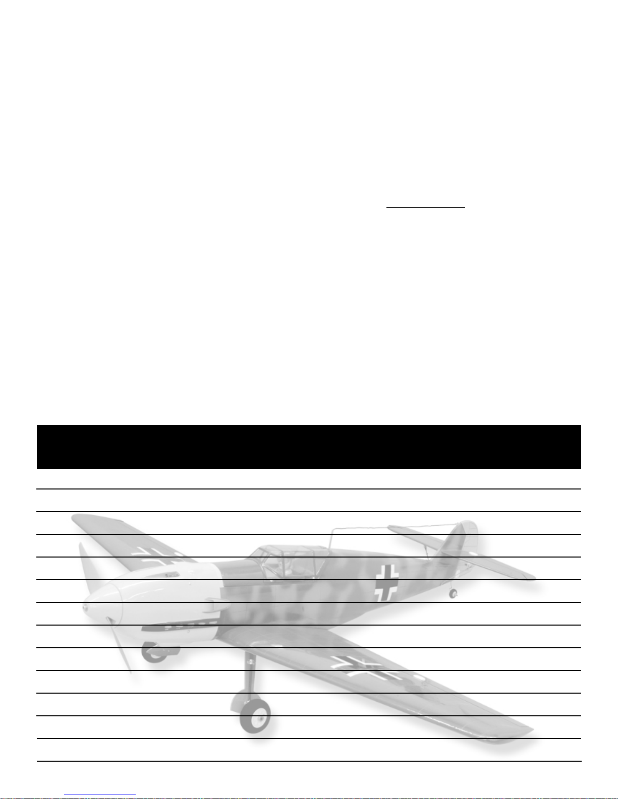
The SIG Messerschmitt Bf-109 ARF is a sport scale model, not
necessarily based on any particular full-scale variant. The
covering is printed with color and markings representing typical
German aircraft of the era, including details such as panel lines
and national markings. The builder can add unit markings and
other details of his own choice to make a convincing replica of this
great German warplane.
The recent and rapid development of super-efficient brushless
electric motors and lithium polymer batteries have made electric
powered aircraft, such as the Bf-109, a practical reality. Our
prototype Bf-109 models have proven to be outstanding R/C
aircraft, both in terms of looks and performance. We have flown
our own prototypes a great deal and can report that they are solid
flying models with honest flight characteristics. When powered
with an appropriately sized brushless outrunner motor swinging
the recommended propeller, the airplane will have a wide speed
range and be capable of some very nice scale fighter plane type
aerobatics. While the SIG Bf-109 ARF is a comfor table model to
fly, we do
not recommend it for a first R/C model. But we can and
do recommend the Bf-109 as your first electric warbird.
This assembly manual will guide you through each assembly step
in detail and is further enhanced with photos that visually assist
you with each step. It is important that you follow the provided
construction sequence to achieve the best results.
Reference Material:
SIG Manufacturing Company, Inc. wishes to gratefully
acknowledge the excellent reference materials listed below:
• http://en.wikipedia.org/wiki/Messerschmitt Bf 109
• http://www.axishistory.com/index.php?id=1154
• "The Great Planes", by James Gilbert, Published by Grossett &
Dunlap, 1970
Specifications: Imperial Metric
Wing Span: 48 in. 1219 mm
Wing Area: 396 sq. in. 25.52 dm
2
Length: 42.5 in. 1079 mm
Flying Weight: 60 oz. 1700 g
Wing Loading: 21.8 oz./sq.ft. 66.6 g/dm
2
Motor: Brushless, 300 to 400 watt
ESC Required: Brushless type to suit motor & battery pack
Battery Pack
Required: 3-Stack 3300 mAh Lithium Polymer Pack Typical
Radio Required: 4 Channel w/ Hitec 2-HS55 and 2-HS81
servos or equivalent
Order Number: SIGRC102ARF
ITEMS REQUIRED TO COMPLETE THIS KIT:
• Radio System - 4-channels, with 4 micro servos (Hitec HS-55 &
HS-81 used & shown in this manual)
• Appropriate servo extensions
(see Radio Systems section for specifics)
• Brushless Motor (see Power System section for recommendations)
• Brushless Speed Control (see Power System section for recommendations)
• Lithium Polymer Battery Pack (see Power System section for
recommendations)
• Propeller (see Power System section for recommendations)
• Motor mounting bolts, sized for your par ticular motor
• Dremel
®
Tool with a variety of sanding bits
• An assortment of screwdrivers
R
1
Messerschmitt Bf-109 ARF ASSEMBLY MANUAL
INTRODUCTION:
The prototype, Messerschmitt Model 109, first took to the air in
mid-September of 1935 and its performance was nothing short of
spectacular! Small, powerful, and fast, Willy Messerschmitt's
Model 109 surely had a date with destiny.
Based on many of the design concepts of the earlier Model 108
Taifun, the Model 109 was exceptionally well constructed and
aerodynamically clean. The concept behind the 109 was to place
the smallest and cleanest airframe possible behind the most
powerful engine available at the time. This resulted in an aircraft
that had many positive attributes, as well as a few negatives. One
of these negatives was the weight of the airplane versus its
relatively small wing. This created a high wing loading, especially
in comparison to its eventual foes . In an attempt to keep the weight
as low as possible, the retractable landing gear pivoted outward
toward the wingtips, keeping the main wing spar weight down. But
as a result, the splayed, close-tracked landing gear would plague
the design for the rest of its operational life. All of this aside, the
Model 109 can truly be called one of the first modern fighter
aircraft of the era.
The Bf-109 was ultimately manufactured in greater numbers than
any other aircraft in history - over 30,000 units between 1939 and
1945. It was manufactured in Germany, Czechoslovakia, and
Spain. To keep the airplane competitive in combat, it went through
many modifications and remained the Luftwaffe's primary fighter
aircraft throughout WWII. Used in a wide variety of combat
missions, the Bf-109 served as an air superiority fighter, a bomber
escort, an interceptor, a ground attack aircraft, and in high-speed
reconnaissance missions. But in its primary role as an air
superiority fighter, the Bf-109 was truly a formidable aircraft. In
fact, at one time or another, every top scoring Ger man fighter ace
flew Bf-109's. Notably, Erich Har tmann, with a combat record of
352 enemy aircraft shot down, always flew a Bf-109, refusing to fly
any other aircraft.
In historical terms, the Bf-109 will always be best remembered for
its role in the Battle of Britain, forever being compared to its
closest adversary of the time, the Supermarine Spitfire. While
these comparisons rage on to this day, it's fair to say that both of
these fine aircraft were among the best of their day.

• Pliers - needle nose and flat nose types
• Wire cutters
• A selection of glues - thin, medium, and thick SIG CA,
SIG Epoxy Glue (5 and 30 minute types) and
SIG Super-Weld white glue
• Fine point CA applicator tips
• Drill with assorted small drill bits
• Pin vise for small diameter drill bits
• Small T-pins
• Sandpaper
• Hobby knife with sharp #11 blades
• Scissors
• Covering iron and trim seal tool
• Paper towels
RADIO SYSTEMS:
The SIG Bf-109 ARF requires the use of a four-channel radio
system and four micro servos. Due to limited space in the wing
bays for aileron servos, we used and can recommend the Hitec
HS-55 (2 required) for this purpose. We used and can recommend
Hitec HS-81 servo for the fuselage-mounted elevator and r udder
servos. These little servos fit into the fuselage tray perfectly and
provide plenty of torque. A sub micro receiver is not mandatory but
smaller receivers like the Hitec Electron 6 do offer great reliability
and considerably lighter weight over larger, standard type
receivers.
Ser
vo Extensions: In order to connect the ailerons ser vos to the
receiver, two 6" ser vo extensions and one standard Y-har ness will
be required. Note that in our radio installation, we leave the "Y"
harness plugged into the receiver, plugging the two aileron servo
extensions into it whenever the wing is attached.
POWER SYSTEMS:
Motor
s: The Bf-109 has been designed to fly with brushless
motors in the 300 to 400 watt range. We have used and can
certainly recommend the fine Himax range of brushless motors for
your own Bf-109 model. W e ha v e tested this airplane with both the
Himax #HC3516-1130 (300 watt) and HC3522-0990 (400 watt)
brushless motors with great results.
Electr
onic Speed Controls (ESC): We suggest using a 35 amp
ESC for 300 watt motors or a 45 amp ESC for 400 watt motors.
Pr
opellers: We suggest using an APC 10 x 7E propeller with
either the 300 or 400 watt motors or an APC 11 x 7E, used only
with the 400 watt motor
Batter
y Packs:We suggest using a 3S 3300 mAh Lithium Polymer
battery pack. Note that this pack fits perfectly in the Bf-109 battery
tray.
Batter
y Charger: Use a charger designed specifically for
lithium polymer batteries! Using any other type of battery
charger for lithium polymer batteries can be extremely
dangerous.
COVERING MATERIAL:
The Bf-109 ARF has been professionally covered in SIG
AEROKOTE
®
iron-on plastic covering material. This covering is a
tough, lightweight, and heat shrinkable material. The camouflage
patterns, national markings, and other detail and panel lines have
been printed on the outer surface of the covering, giving a very
realistic overall look to the model. The inks used in the printing
process are quite durable and bond to the covering film extremely
well. Normal handling and flying conditions should have little, if any
effect on the printed finish. However, carefully note that certain
solvents can and will soften the ink, allowing it to be rubbed off.
The following is a short list of cleaners and solvents that can and
cannot be used on the printed finish of your model:
Use
Do Not Use
Windex®Window Cleaner CA Debonder
SIG Model Magic Cleaner Acetone
Hexane Alcohol
Dope Thinner
If in doubt of the suitability of a cleaner or chemical to use on your
model, always test it first, choosing an inconspicuous location on
the model. In addition to the above, carefully note that excessive
heat from typical covering tools, such as heat guns, covering irons
and trim seal tools, may also soften and remove the ink finish.
Work only with temperatures set at 250
O
F or less. Whenever
working on the covering with a heat iron, we strongly suggest that
you first cover the shoe of the iron with a soft cotton cloth, such as
an old T-shirt.
Your Bf-109 ARF kit was built and covered in a part of the world
that has a great deal of humidity. You may therefore notice that
after the covered parts have been removed from their plastic bags,
that some wrinkles may appear after 24 to 48 hours. This is
perfectly normal and is the result of the wood losing humidity and
dimensionally shrinking.
If wrinkles appear in the covering, they are easy to remove, using
a little heat. Because of the ink printing, it is not
advisable to rub a
hot iron over the surfaces to be tightened. If proper precautions
are taken, a heat gun will do the job quickly. First, locate and
inspect all the seams where the covering overlaps like at the
leading and trailing edges of the wing and tail surfaces and the top
and bottom of the fuselage. Seal these overlaps down with a trim
iron (set to about 220
O
F to 240OF) by applying the iron to the seam
overlap for a few seconds without moving the iron, then lift the iron
to move to the next location and repeat. Do this until you are sure
that all the seams are secure before proceeding with the heat gun.
Protect these seams with wet paper towel strips while you shrink
the loose areas with the heat gun. Use caution to never use any
more heat than necessary to get the covering to shrink.
COMPLETE KIT PARTS LIST:
The following is a complete list of all parts contained in this kit.
Before beginning assembly, we suggest that you take the time to
inventory the parts in your kit, using the provided check-off boxes
(❑). Carefully note that the CA type hinges for the rudder,
elevators, and ailerons are in place in their appropriate locations
but are not glued in place. All parts are covered in pre-printed
AeroKote
®
with green and blue-gray camouflage colors with panel
lines and other details except where noted.
❑ Bag #1 Ver tical fin and rudder, 2 CA hinges installed but not
glued, leading edge of rudder at the bottom drilled and
routed to receive the tail wheel wire.
❑ Bag #2 Stabilizer and elevator, 4 CA hinges installed but not
glued, elevator joiner wire installed but not glued.
2
3
❑ Bag #3 Full Span Wing, ailerons installed with 3 CA hinges on
each but not glued, aileron servo hatches installed
with 4 ea T2 x 6 mm PWA screws
❑ Bag #4 Fuselage with top hatch/cockpit installed and retained
by magnets, motor mount/battery tray installed, two
plastic pushrod tubes installed, blind nuts for wing hold
down bolts installed, servo tray installed.
❑ Bag #5 Clear Canopy with frame painted on, 4 holes drilled for
mounting screws.
❑ Sub bag 4 ea. T2 x 6 mm PWA screws
❑ Bag #6 Fiberglass cowl - painted yellow.
❑ Sub bag 4 ea. T2 x 12 mm PWA screws
❑ Bag #7 Wire Pushrod bag
❑ 2 ea.
1.25 mm dia.x 597 mm
with "Z" bend on one end
❑ 2 ea.
1.25 mm dia. x 98 mm
with "Z" bend on one end
❑ Bag #8 Tail Wheel Assembly with 25 mm dia.Wheel
❑ Bag #9
Green covering material for repairs, 2 ea. 110 mm x 30 mm
❑ Bag #10 Control Horn bag
❑ 4 ea. Control hor ns
❑ 4 ea. Backing plates
❑ 4 ea. Pushrod connectors with set screws
❑ 4 ea. Metal keeper washers
❑ 8 ea. M2 x 20 mm bolts
❑ Bag #11 Accessory Bag with 2 ea. Plywood landing gear doors
painted gray, drilled for mounting bolts and air scoop
for fuselage.
❑ Sub bag ❑ 4 ea. Metal straps to retain landing
gear doors
❑ 8 ea. M2 x 8 mm bolts
❑ 8 ea. M2 nuts
❑ 8 ea. M2 washers
❑ Bag #12 ❑ 2 ea. plywood washers, 24 mm dia. - painted gray
one side.
❑ 2 ea. M4 x 30 mm plastic wing hold down bolts
❑ Bag #13 Spinner Bag with yellow painted plastic spinner cone
❑ 1 ea. 72 mm dia. x 4.5 mm plywood backplate
❑ 2 ea. 20 mm dia. x 2mm plywood washers for
spacers
❑ Bag #14 ❑ 2 ea. Painted plastic wing radiator covers
❑ Bag #15 ❑ 4 ea. 8 mm square x 12 mm hardwood for wing
servo mounts
❑ Bag #16 Tail Brace Bag - all parts painted gray
❑ 2 ea. 2 mm dia. x 94 mm wire threaded M2 on one
end and an eyelet bent on the opposite end
❑ 2 ea. M2 R/C metal R/C links
❑ 2 ea. M2 knurled lock nuts
❑ Sub bag ❑ 2 ea. Metal tabs, drilled two places
and bent in center
❑ 2 ea. T2 x 6 mm PWA screws
❑ 2 ea. T2 x 8 mm PWA screws
❑ 2 ea. 3 mm ID x 6 mm silicone tube
keepers
❑ Bag #17 Main Landing Gear Bag
❑ 2 ea. 4 mm dia. Wire landing gear wires -
pre-bent
❑ 2 ea. 63 mm dia. Light foam wheels
❑ Sub bag ❑ 4 ea. Plastic retaining straps
❑ 8 ea. T3 x 8 mm PWA screws
❑ 2 ea. 4.1 mm ID wheel collars
with set screws
❑ 2 ea. 4 mm ID plastic bushings
NOTE: In this manual, all references to "right" or "left" refer to your
right or left, as if you were seated in the cockpit looking forward.
WING ASSEMBLY:
The following parts will be required for this assembly sequence:
❑ Wing
❑ 4 ea. ser vo mounting blocks from Bag 15
❑ 2 ea.
Hitec HS-55 or similar sized aileron servos - not included
❑ 2 ea. 6" ser vo wire extensions - not included
❑ Bag #10 2 ea. Control hor ns
2 ea. Backing plates
2 ea. Pushrod connectors with set screws
2 ea. Metal keepers,
4 ea. M2 x 20 mm bolts
❑ Bag #12 2 ea. Painted plywood wing bolt washers
2 ea. M4 x 30 mm nylon wing bolts
❑ Bag #7 2 ea. .048 x 3-7/8 (98 mm)
wire pushrods with Z-bend
❑ Bag #11 2 ea. Landing gear doors with hardware
❑ Bag #14 Radiator covers
❑ Bag #17 Landing gear wires with mounting hardware
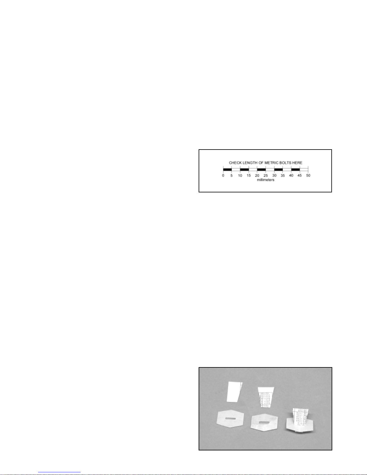
❑ 1) As noted above, the hinges for the ailerons are not yet
glued. The first step is to remove the left and right ailerons and the
hinges from the wing. The hinges have a die-cut center slot that
can be used to accurately place and center the hinge equally into
4
can be used to accurately place and center the hinge equally into
both the wing panel and the aileron. To do this, use a business
card and a pair of scissors to cut some "wedges". These should
be wide enough at the top so as to not pass through the hinge slot
cut-out. Insert each hinge in place into the wing panel up to the
cardboard wedge.
Now, slip the aileron onto each hinge, pressing it fully in place.
Center the aileron, leaving equal spacing between each end of the
aileron and the wing.
❑ 2) Flex the aileron down a 1/2" or so to expose the center of
the hinge and use a piece of masking tape to hold it in this
position. Remove the wedge from one of the hinges and apply
three drops of thin CA to each exposed side of the hinge. Repeat
this operation until all the hinges on this side of the wing are glued.
IMPOR
TANT: - Be careful to avoid getting glue on the covering.
Solvents such as CA debonder will also remove the ink on the
covering.
❑ 3) Remove the tape holding the flexed aileron, returning it to
the neutral position. Turn the wing over and flex the aileron down
about 1/2", again exposing the center of the hinges. Use another
piece of tape to hold the aileron in this position. Repeat the same
gluing process on each hinge - 3 small drops of thin CA on each
exposed side of each hinge. Remove the tape holding the aileron
and return it to the neutral position. Hold the wing up to the light
and look through the gap between the aileron and the wing for any
excess glue that may have accumulated in the gap. Inserting a
slip of paper into the hinge gap, on each side of the hinges, will
wick out any excess CA glue . Hinge the opposite aileron using the
same procedure.
Note that it typically takes a little time for CA glue to fully "wick" its
way across the surface of the hinge and surrounding wood. Allow
about 10 minutes or so before flexing the ailerons. After sufficient
time has passed, firmly flex each aileron briskly up and down to
create free and easy movement. We also suggest pulling on the
aileron at each hinge location, making sure each hinge is firmly in
place.
❑ 4) Remove the four screws from each corner of both aileron
servo covers on the bottom of the wing. With the aileron ser vo
covers out of the way, remove the covering from the slot that has
been cut for the servo arms.
❑ 5) Install straight servo arms onto two HS-55 servos, orienting
the arms at 90
O
to the servo body. Note that these extra arms
come with the servos and are about 1-7/32" long, end to end.
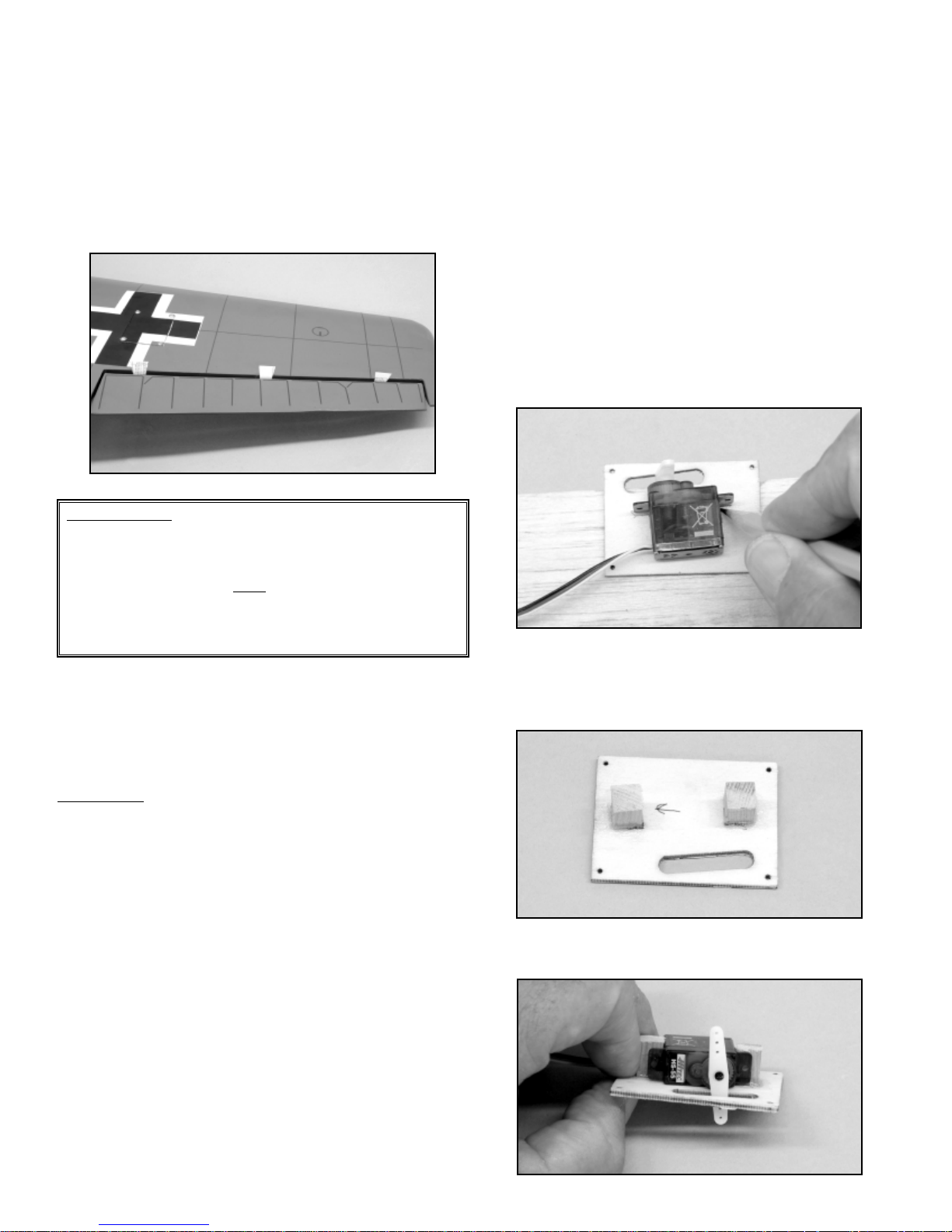
❑ 6) Lay the servo onto the inside surface of the aileron hatch,
positioning the servo arm centered in the slot, with the servo body
within the borders of the hatch. Hold the servo in this position and
use a pencil to mark where the bottom of the servo mounting lugs
and sides of the servo case meet. This marks position of the two
wooden servo mounts.
❑ 7) Locate the four 8 mm square x 12 mm long hardwood
blocks from bag #15. These are glued on end, to the servo hatch,
at the location marks just made. 5-minute epoxy or thick CA glue
works well for this purpose. Allow the glue to fully set.
❑ 8) Place the servo back onto the hatch between the two
mounting blocks. Use a sharp pencil to mar k the servo mounting
Important Note: When installing CA type hinges, more is not
better! Applying excess thin CA glue to this type of hinge does
nothing more than stiffen it, potentially causing the hinge to
crack and break. If you have followed these instr uctions, each
hinge will have a total of 6 small
drops of thin CA glue on each
side. This is the correct amount of adhesive for the pur pose.
Using a fine tip applicator for this purpose is strongly advised
and recommended.

5
hole locations onto the mounting blocks.
Remove the servo and drill pilot holes for the servo mounting
screws into the wood mounting blocks, using a #60 (1 mm) bit.
Use the mounting screws that came with your servo to secure the
servo to the mounting blocks.
Repeat this same procedure with the remaining aileron servo and
servo hatch.
❑ 9) In this step, the servo arms will be centered onto the servo
output shaft. First, remove the ser vo output arm retaining screws
and remove the servo output arms. Connect the two aileron
servos leads into a standard "Y" harness. Plug the "Y" harness
into the receiver. Tur n your transmitter on and center the aileron
trim to neutral. Connect the receiver to a 4.8v battery pack. With
the system now on and working, reattach the two servo output
arms onto the two aileron servos, with the arms at 90
O
(or as close
to 90
O
as possible) and reinstall the output arm retaining screws
into each servo. If your radio system has "sub trim" capability, use
this feature to further center the output arms at 90
O
to the servo
body and centered within the servo hatch slot. Once the output
arms are both centered, cut off the opposite, unused end of each
arm. This ensures that the arm will not contact the covering on the
inside top of the wing when the servo tray is installed. Turn the
radio system off and unplug the servo leads from the "Y" harness.
❑ 10) Connect a 6" ser vo lead extension onto each aileron servo
lead. We always suggest securing these extensions at the
connectors, using a length of heat shrink tubing. This ensures that
the connection remains secure.
❑ 11) On the top surface of the wing, near the center joint, you will
be able to feel the location of two 1/2" diameter holes through the
covering. These are the exit holes for the aileron servo leads. Use
a sharp #11 blade to remove the covering from these holes. You
should then be able to see a small stick tack-glued to the inside top
sheeting with a string attached to it. This is the pull string, used to
pull the aileron servo leads through the wing ribs.
❑ 12) Inside the aileron ser vo bay in each wing panel, the other
end of this string is attached to a small tack-glued stick. Break this
stick loose and unwind the string from the stick. This end of the
string is secured firmly to the connector end of the servo extension
lead (we like to tie this string tightly to the connector). With the
string in place to the connector, feed the connector and string into
the servo bay while gently pulling on the string at the exit hole in
the center of the wing. Start the connector down through the holes
in the wing ribs. Lightly pull back and forth until the connector
moves through one rib and up to another . Keep doing this until the
connector appears at the exit hole. Pull the connector up through
the hole and temporarily tape it to the wing surface. Now, mount
the servo hatch and servo in place to the bottom of each wing
panel, using the provided screws, removed earlier. Repeat this
procedure with the opposite servo hatch and wing panel.
❑ 13) With both servo leads now through their respective exit
holes on the top center of the wing, remove the strings and plug
each lead into a standard "Y" harness. Again, we suggest
securing these connections with short lengths of heat shrink
tubing.
❑ 14) The aileron control horns are now installed onto the bottom
surfaces of each aileron. The vertical center arm of the control
horn is located 1-1/2" from the inboard from the end of the aileron,
with its four hole locations lined up with the hinge line. Hold the
control horn in this position and use a sharp pencil to mark the two
control horn mounting hole locations onto the surface of the
aileron.
At the two marks just made, use a #46 (2 mm) dia. bit to drill two
clearance holes completely through the aileron, 90
O
perpendicular
MODELER’S TIP: It happens to all of us now and then; the
factory installed servo lead string disappears into the wing! No
problem. Simply pull the string completely out of the wing and
attach a small weight, such as a metal nut or even a small split
shot sinker, to one end of the string. Insert the weighted end of
the string into the servo opening and start it down the holes that
are just behind the spars. With the wing on end and the center
of the wing below the servo well, gently shake the wing while
feeding the in the weighted string, listening for the weight to
drop through to the next rib. When the center section is
reached, turn the wing upside down and shake the weight out
of the hole and you're back in business!
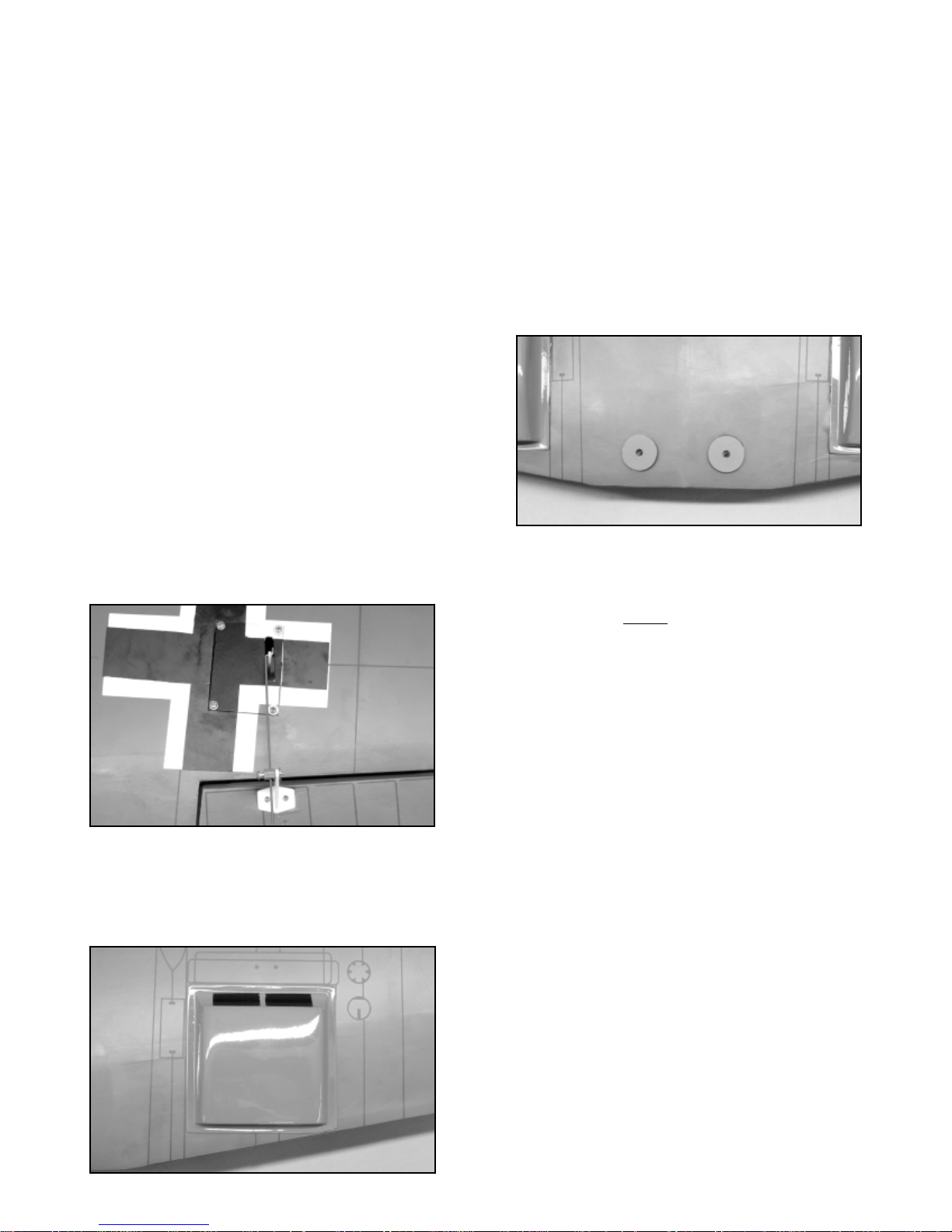
trailing edge. These two lines are used to align the radiators. The
black painted inlet side of these covers faces forward towards the
leading edge, with the front of the cover even with the rectangle
and the inside edge of the cover on the chordwise line. You may
need to slightly trim the rear outboard corner of the cover to keep
it from hanging over the trailing edge. We suggest using medium
or thick CA glue to attach these covers in place, being careful to
not use excessive glue that might smear the outer surface of the
cover or the cover ing itself.
❑ 18) Use a sharp #11 blade and hobby knife to no w open the two
wing hold down bolt holes at the trailing edge of the wing center
section. Use medium or thick CA glue to glue the two painted
plywood washers in place, centered over the two bolt holes in the
wing.
MAIN LANDING GEAR INSTALLATION:
This assembly sequence assumes that the optional main landing
gear and related parts will be installed. Note that if you intend to
fly your Bf-109 model without
landing gear, you can then proceed
to the Motor Installation section. The following parts will be
required for the following assembly steps.
The parts for the main gear are found in these bags:
❑ Bag #17: 2 ea. 4 mm wire landing gear legs
2 ea. 63 mm dia. main wheels
4 ea. plastic retaining straps
8 ea. T3 x 8 mm PWA screws
2 ea. 4.1 mm ID wheel collars with setscrews
2 ea. 4 mm ID plastic bushings
❑ Bag #11: 2 ea. plywood landing gear doors
4 ea. metal straps
8 ea. M2 x 8 mm bolts
8 ea. M2 nuts
8 ea. M2 washers
❑ 1) As received, the wing structure includes two slotted
hardwood main landing gear mounting blocks, built into the bottom
surfaces. These blocks are used to mount and secure the main
landing gear wire forms.
On the bottom of the wing center section, about 2-1/4" (57 mm)
back from the wing leading edge, you will be able to feel the two
slots that will hold the main landing gear legs. Press firmly on
these slot locations with your finger, moving back and forth on the
surface of the wing until you can see where the edges of these
slots are. Once the slots are located, use a shar p #11 blade to
carefully slit the covering from one end of the slot to the other.
Repeat this with the opposite landing gear slot.
to its bottom surface. Repeat this process on the opposite aileron.
Use the four M2 x 20 mm bolts and the two plastic control horn
backing plate to now mount each aileron horn to the bottom of
each aileron with the backing plates on top of each aileron to
engage the bolt ends. Cut off the excess bolt ends and file smooth.
❑ 15) Install a pushrod connector, pointing towards the center of
the wing, into the outermost hole in the control horn and secure it
with a metal keeper washer, pressed in place over the stub end.
Repeat this process with the remaining pushrod keeper and
keeper washer.
❑ 16) Insert the Z-bend end of the .049" dia.x 3-78" (1.25 mm dia.
x 98 mm) aileron pushrods into the outermost hole of the aileron
servo arms. Note that these holes may need to be slightly
enlarged to fit the wire diameter. Slide the opposite, unbent end of
the pushrod into the hole in the pushrod keepers on the aileron
control horns. Again, connect the aileron "Y" harness into the
aileron receptacle in the receiver. Turn the transmitter on and
connect a 4.8V battery pack into the receiver. With the aileron
servos now working, make sure the trims are at neutral and then
tape the ailerons in neutral to the wing. Now firmly tighten the
setscrews in the pushrod keepers to lock the pushrods in place.
Remove the tape from the ailerons and wing. Move the aileron
stick on the transmitter to move the ailerons. Viewed from the rear
trailing edge of the wing, the right aileron should move up when the
aileron stick is moved to the right. If this aileron movement is
wrong, reverse the aileron channel in your transmitter. Once
satisfied, disconnect the aileron "Y" harness and battery pack from
the receiver and turn off the transmitter.
❑ 17) The two plastic wing radiator covers (Bag #14) are now
glued in place onto the bottom of each wing panel. Notice that
there are lines printed chordwise on the bottom covering that are
about 3-11/16" (94 mm) out from the center of the wing. A
rectangle intersects this line about 4-7/16" (113 mm) forward of the
6
freely with just a small amount of left and right "play". Once in
position, firmly tighten the setscrew in the wheel collar. Repeat this
process with the remaining wheel.
The wing assembly is now complete and ready to use. Set it aside
for now.
MOTOR, RECEIVER, & ESC INSTALLATION:
The following parts are not included in your kit. These will be
required for the following assembly steps:
❑ Motor of choice
❑ Mounting bolts & washers for your specific motor
❑ Prop adaptor for your specific motor shaft
❑ Electronic speed control (ESC)
❑ Receiver
❑ 3" or 4" of Velcro
®
for mounting the receiver & ESC
Note: The metal motor mount in the Bf-109 has been designed to
accommodate the front mounting of most 35 mm diameter motors.
The small holes give a general location for the tapped holes
in the front of your motor. Enlarge or slot them as needed
to accommodate your specific motor. We have used Himax
HC3516-1130 and HC3522-0990 motors with the proper speed
controls, props, and 3S1P LiPo 3300 mAh batteries in the
prototypes and have been very satisfied with the performance and
duration of these setups. We will show the HC3522-0990 in this
manual as a typical motor installation.
❑ 1) Feed the motor wires through one of the openings next to
the front motor mount plate and position the motor up to the back
side of the front mounting plate. Bolt the motor to the mounting
plate using the appropriate bolts and washers for your specific
motor. We always suggest using a non-permanent thread-locking
compound for these bolts, such as Loctite
®
"Blue". This simple
precaution works very well to keep these bolts in place under
vibration.
7
❑ 2) Attach the gear doors to the inside of the gear legs using
the metal clips, M2 x 8 mm bolts, M2 nuts, and M2 washers. Note
that the bottom edges of these doors are made with two distinct
angles. The more highly angled edge should be oriented toward
the rear of the wing to providing better ground clearance.
❑ 3) Insert the wires into the landing gear blocks in the wing, with
the legs and doors offset to the front leading edge of the wing. The
wheel axles should be close to the leading edge when viewed from
above and aligned with each other in a straight line or a slight toe
in position. It might be necessary to slightly "tweek" the axle wires
to achieve alignment. If so, do this now.
❑ 4) Once satisfied with the axle alignment, secure both landing
gear wires into the wing bottom using the four plastic retaining
straps, as shown. Hold the strap in place and mark its two hole
locations onto the surface of the wing. Use a 3/32" dia. bit to drill
pilot holes for the mounting screws. Repeat this process for the
remaining landing gear straps. Secure the straps in place with
T3 x 8 mm PWA screws.
5) The main wheels are now installed and secured. Slide a
plastic bushing over the axle wire, all the way to the bend. Slide
the main wheel in place onto the axle, followed by the wheel collar.
The wheel collar should be positioned to allow the wheel to turn

RUDDER & ELEVATOR SERVO INSTALLATION:
As mentioned earlier, the rudder and elevator ser vos do not need
to be the sub-micro type used for the aileron servos. We used
Hitec HS-81 servos in our Bf-109 prototypes to take advantage of
their higher torque.
In the following steps you will need the following parts:
❑ 2 ea. 1.25 mm dia. x 597 mm wire pushrods
❑ 2 ea. Rudder & elevator servos (not included)
❑ 1) From the kit contents, locate the tw o 1.25 mm dia.x 597 mm
wire pushrods. Note that these pushrods are supplied with a "Z"
bend at one end - this is the end that will attach to the servo
output arm. From the canopy/hatch opening in the fuselage, insert
the straight ends of the pushrods all the way into the two guide
tubes behind the servo tray. Straighten these pushrods as needed
to get smooth and easy travel.
Note:
The pushrod guide tubes cross within the fuselage so that
the pushrod for the elevator exits the left side of the fuselage while
the servo is on the right side of the servo tray and the rudder is just
the opposite.
❑ 2) Prepare the two servos for installation by first inserting the
rubber grommets and eyelets - supplied with the servos - into the
mounting lugs at each end. Remove the servo arm retaining screw
from each servo and then the servo arms.
❑ 3) Place the servos into the top of the servo tray. Slide the
servo to the outside of the servo tray opening and hold it there.
Use a pencil to mark the servo mounting hole locations onto the
servo tray. Repeat this process with the remaining servo . Remove
the servos from the tray and use a 1/16" dia. (1.5 mm) bit to drill
pilot holes at the mounting marks just made. Reinstall the ser vos
and secure them to the tray using the mounting screws that came
with them. Note that the output ends of these two servos are
towards the front of the fuselage.
❑ 4) With the servos now mounted, check the relationship
between the two servo output arms when they are in place on the
servos. If there is any interference, then you will have to select or
modify servo arms that will not contact or interfere with each other
during the operation of the servos. Remove the servo arms, then
fit the "Z" bend ends of the pushrods onto the selected servo
output arms and place the arms back onto the servos with the
connected drive arms at 90
O
to the servo body as shown.
❑ 2) Working through the fuselage wing saddle opening, feed
the motor wires from your ESC forward into the nose, under the
battery tray, until they exit below the motor. Plug the motor wires
into the corresponding wires from ESC and then, slide the excess
wiring back under the battery tray. Make sure to arrange these
wires so that they do not contact the motor.
❑ 3) The ESC is now secured to the bottom of the battery tray,
ahead of wing. W e suggest using Velcro
®
for this purpose. With the
ESC now in place, feed the ESC battery connector wire along the
side of the battery tray, up to the top of the tray.
❑ 4) The receiver is now installed into the fuselage on the
bottom rear surface of the battery tray. Again, we suggest using a
length of Velcro
®
for this purpose. Insert the ESC receiver lead into
its appropriate throttle receptacle in the receiver. Using your
transmitter and flight battery, connect the battery to the ESC
battery connector and test the motor throttle function. Also, make
sure the motor is turning in the correct direction. Disconnect the
flight battery and turn off the transmitter.
8
spinner backplate in its running position, allowing the cowl to be
accurately mounted to the fuselage.
❑ 3) Position the front of the cowl to contact the spacers on the
back of the spinner backplate and then, center the cowl to the
backplate in both top and side views. Use tape to hold the cowl to
the backplate in this centered position. Use a few more pieces of
tape to hold the cowl to the fuselage at its back edges. The cowl
should now be firmly and accurately in position. Using a #60 (.040"
dia.) bit, drill four pilot holes through the plywood pads beneath the
four pre-drilled holes in the cowl.
❑ 4) With a screwdriver, install the four cowl mounting screws
through the holes in the cowl and into the plywood pads. Tighten
the screws just enough to place the washer head in contact with
the cowl - no more. Remove the pieces of tape, the propeller nut,
the propeller, and the plywood backplate. Remove the 1/16"
spacers from the rear of the backplate and lightly sand the
backplate smooth.
MOUNTING THE T AIL SURF ACES:
In the following steps you will need the following par ts:
❑ Bag #1 Vertical fin and rudder assembly
❑ Bag #2 Horizontal stabilizer and elevator assembly
❑ Bag #12 2 ea. M4 x 30 mm Nylon wing bolts
❑ 1) Remove the elevators, rudder, and hinges from the tail
surfaces. Insert the vertical fin into its slot at the top rear of the
fuselage. It should bottom out on the built in platform at the bottom
of the slot. The trailing edge of the fin should be in perfect
alignment with the vertical tailpost of the fuselage - slide it forward
or back until it is aligned. Next, use a sharp, soft pencil to mark
both sides of the fin where it meets the fuselage at the slot.
Remove the fin from the fuselage and use a sharp #11 blade to
The servos are now tested using the radio system. Connect the
appropriate rudder and elevator servo leads into the receiver, tur n
on the transmitter, and connect the flight battery to the ESC lead.
Make sure the rudder and elevator trims are at neutral. Test the
servos with the transmitter for proper movement and the alignment
of the servo arms at neutral. If necessary, reposition the output
arms to align them at 90
O
to the servo body at neutral. With arms
now positioned correctly, reinstall the servo output arm retaining
screws. Unplug the flight battery and turn off the transmitter.
MOUNTING THE COWL:
In the following steps you will need the following par ts:
❑ Fuselage with motor mounted
❑ Prop adaptor part for your specific motor
❑ Flight propeller.
❑ Bag #6 Sub bag containing four (4) T2 x 12 mm PWA
cowl mounting screws
❑ Bag #13 1 ea. Plywood spinner back plate
❑ 1) Mount prop adaptor on the motor output shaft and secure it
in place. The provided plywood spinner backplate has a center
hole diameter of 6 mm (just under 1/4"). This hole will likely have
to be opened up to fit onto your propeller adaptor. Do this now.
After establishing a good concentric fit, remove the plywood
backplate from the adaptor. Tack glue four (4) 1/16" (1.5 mm) thick
spacers to the back surface of the backplate , as shown. These will
properly locate the cowl in relationship to the spinner. These
spacers will be removed shortly.
❑ 2) Slide the cowl in place onto the front of the fuselage,
moving it back until the front of the cowl is slightly behind the face
of the prop adaptor. Slip the spinner backplate onto the prop
adaptor shaft with the 1/16" spacers towards the cowl. Place the
propeller in position onto the prop adaptor shaft and tighten it
in place with a propeller nut. This set-up should now have the
9
❑ 4) The two elevator halves are now joined. We suggest using
15-minute epoxy for this step. Apply glue to the two joiner slots at
the inboard leading edge ends of each stabilizer half. Use a small
diameter piece of wire or a pin to also apply glue into the joiner
holes in each elevator half. Press the wire elevator joiner in place
into each elevator half and quickly remove any excess glue. Place
the elevator assembly on a flat wor k surface, protected with wax
paper. Use a straightedge to align the elevator leading edges with
each other, as shown. Allow the glue to fully cure before handling.
❑ 5) In preparation for accurately gluing the tail group to the
fuselage, first mount the wing to the fuselage using the two
M4 x 30 mm nylon wing bolts.
Without using any glue, slip the fin/stabilizer assembly into the fin
slot at the top rear of the fuselage. With the airplane on a flat
surface and with the tail raised to approximately level, stand back
and sight the model from the rear. What you want to see is the
horizontal stabilizer perfectly level with the wings and the vertical
fin sitting at 90
O
upright. If the stabilizer tilts one way or the other,
lightly sand the bare wood on the bottom of the fin on the side that
is low , until the stabilizer aligns properly. Once satisfied with the fit
and alignment, remove the fin/stabilizer assembly from the
fuselage.
❑ 6) Lightly coat the bare wood gluing surfaces on both sides of
the fin with SIG Super-Weld white glue. Then, lightly coat both
sides of the fin slot in the fuselage, again with white glue. Carefully
slide the fin into the fuselage slot and wipe off any excess glue with
a wet paper towel. As before, check, and then, double check the
alignment. The trailing edge of the fin is in alignment with the
fuselage tail post, the horizontal stabilizer is perfectly level with the
wings and the vertical fin is sitting at 90
O
. If needed, a strip of
masking tape can be used to hold proper alignment while the glue
dries.
Once the glue has dried, remove the wing from the fuselage.
carefully cut the covering about 1/32" below the line just drawn.
Remove the cover ing, exposing the wood.
❑ 2) Insert the stabilizer into the slot in the vertical fin until the
trailing edge of the stabilizer is about 1/16" f
orward of the trailing
edge of the fin. Again, use a sharp, soft pencil to mark the top and
bottom stabilizer intersection lines onto each side of the vertical fin
and the top and bottom of the stabilizer, where it intersects the
rudder. Remove the stabilizer. Use a shar p #11 blade to carefully
remove the covering from each side of the fin and stabilizer,
between the two lines - make these cut lines about 1/32" inside of
the drawn lines and use only enough pressure to cut through the
covering, not
the wood. Remove the cover ing to expose the wood
beneath.
❑ 3) The vertical fin and horizontal stabilizer are now glued
together, accurately squared to one another, as shown. We highly
recommend the use of SIG Super-Weld white glue for this step
because it allows a little working time, dries clear, and provides a
very strong bond. If needed, a strip of tape works well to hold
these parts in the properly squared position.
10

the plastic control horn backplate to secure the control horn in
place. Cut-off the excess bolt ends and file smooth.
❑ 3) The rudder control horn is now installed onto the bottom
right side of the rudder. As shown, the control horn is positioned
1-1/8" up from the bottom leading edge of the rudder, with the four
R/C link holes in line with the leading edge of the rudder. Hold the
horn in this position and use a pencil to mark the two mounting
hole locations onto the rudder. Again, use a #46 bit to dr ill two
mounting holes through the rudder at the marks just made. Use
the two remaining M2 x 20 mm bolts and the plastic control horn
backplate to secure the horn in place. Cut off the excess bolt ends
and file smooth.
❑ 4) The elevators are now hinged to the horizontal stabilizer.
The hinging method is the same as described earlier for the
ailerons. Use card wedges to center the hinges and remember to
use a fine-tip applicator on your thin CA bottle to keep from getting
any excess glue on the cover ing.
❑ 5) The rudder can now be hinged in place to the vertical fin
and fuselage. Note that the bottom hinge slot entry location in the
tailpost of the fuselage should be opened a little more to accept the
tail wheel bearing diameter. As we did with the rudder, use a short
length of scrap wire to lightly force this area open, to accept about
one half of the bearing diameter when the rudder is fully in place.
We also found that the bottom hinge slot needs to be opened up a
little more to accept the thickness of the brass hinge. This can be
easily done with a #11 blade or even a #27 X-acto saw blade.
Using the two remaining CA hinges, trial fit the rudder fully in place,
making sure it has free movement. Make any adjustments
necessary to achieve this. Once satisfied with the fit and
movement, remove the rudder, leaving the CA hinges in the
vertical fin. Carefully apply a thin coat of Vasoline
®
to the tail wheel
bearing area to protect it from excess glue. The brass tail wheel
hinge is glued in place using 15-minute epoxy. First, place two of
the card wedges into the center CA hinge slots. Next, lightly coat
both sides of the brass hinge half with epoxy glue. Use a piece of
business card to now work some epoxy glue into the fuselage
hinge slot, cleaning up any excess. Now, insert the brass hinge
half partially into its slot in the fuselage and engage the two CA
hinges into their slots in the rudder. Press the rudder in place to
the fuselage and fin.
The two rudder CA hinges can now be glued in place using the
same method described earlier during the hinging of the ailerons.
Allow time for the CA glue to fully wick across the surface of the
HINGING THE CONTROL SURFACES:
The following steps will require the following par ts:
❑ Rudder & elevator with CA hinges - 6 hinges total
❑ Bag #8 - Tail Wheel assembly
❑ Bag #10 - 2 ea. Control horns
2 ea. Control horn backing plates
2 ea. Pushrod connectors
2 ea. Connector keepers
4 ea. M2 x 20 mm bolts
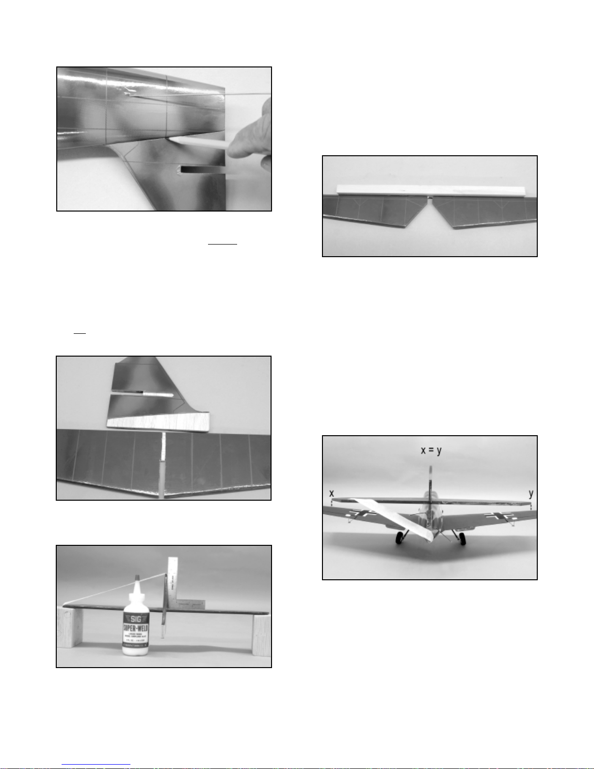
❑ 1) The steerable tail wheel assembly is now installed into the
bottom leading edge of the rudder. Note that this assembly is also
the bottom hinge for the rudder. Because of this, a little extra
clearance must be made to accept the brass tail wheel bearing.
The rudder has been factory slotted for the brass hinge. The
leading edge of this slot should be opened up a little more to
accept at least one half of the bearing. We did this with a scrap
piece of wire that was about the diameter of the bearing. Simply
press this wire firmly into the slot area, forcing it to open a bit more.
Trial-fit the tail wheel assembly in place to check the bearing fit.
Once the bearing fits freely, the tail wheel assembly/hinge can be
glued in place to the rudder. We suggest first coating the bearing
area only with some Vasoline
®
to protect it from accepting glue and
locking up. Use 15-minute epoxy to glue the tail wheel assembly
and hinge into the bottom of the rudder. Carefully remove any
excess glue and allow the glue to fully cure.
❑ 2) The elevator control horn is now installed onto the bottom of
the left elevator half. As shown, the center of the control hor n is
located 1-3/16" outboard of the inner elevator trim line. In top view,
locate the control horn at this position, with its four vertical R/C link
holes in line with the leading edge. Hold the control horn in this
position and mark its two mounting holes onto the surface of the
elevator. Use a #46 (.081" dia.) bit to dr ill two holes through the
elevator at the marks just made. Use two M2 x 20 mm bolts and
11
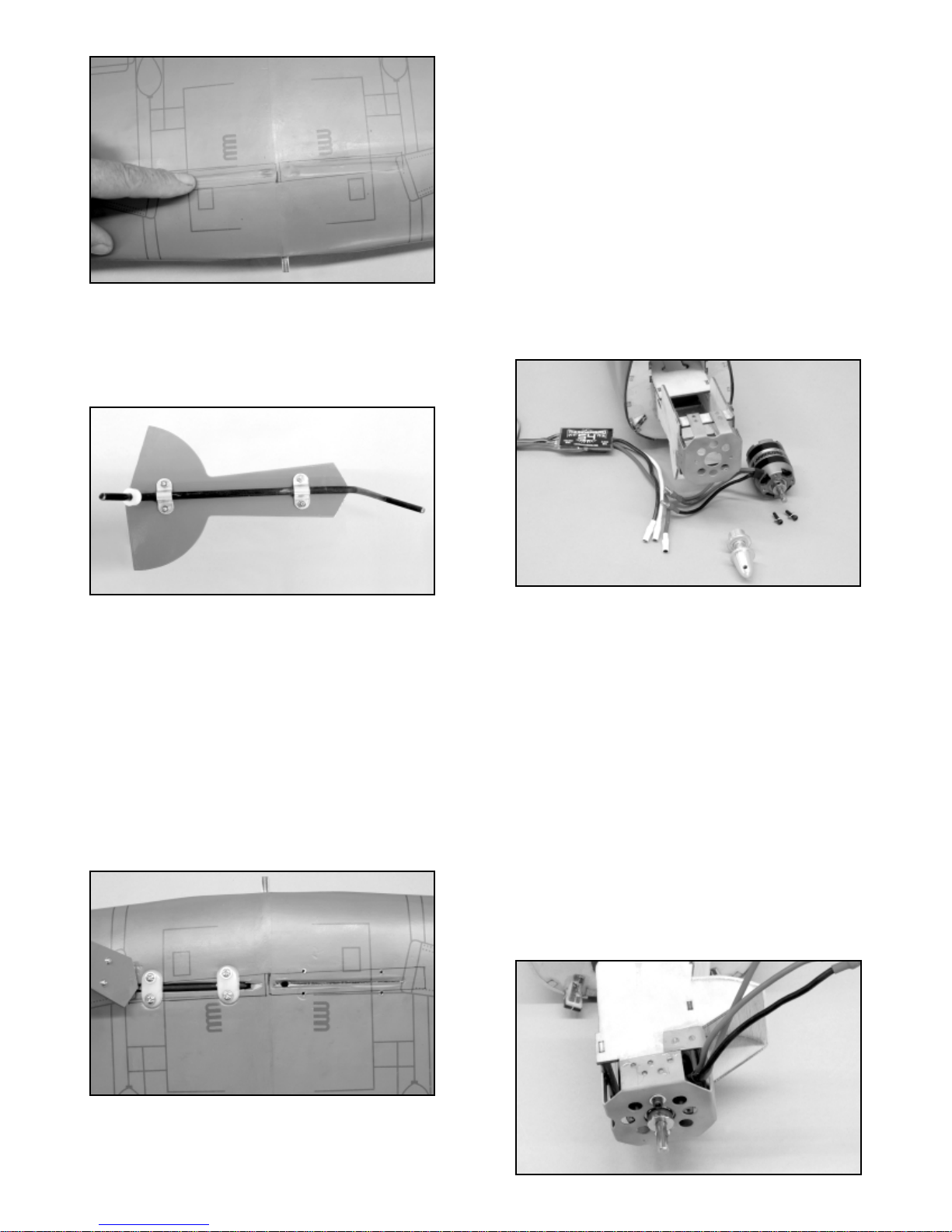
❑ 1) Mark the location of the metal mounting tabs on the bottom
of the stabilizer. Measure 3-3/16" (81 mm) from the side of the fin
on each side. This should be about the center of the hardwood rib
in the stabilizer. From the elevator hinge line, measure 1-1/2"
(38 mm) forward. The intersection of these two marks is the
mounting location for the metal mounting tab. Use a sharpened
awl to puncture the covering and a little of the hardwood rib. Use
two T2 x 6 mm PWA screws to mount the two metal tabs to the
bottom of the stabilizer, as shown.
❑ 2) Adjust the two braces for length. They should both be 4"
(101 mm) long, measured from the pin of the R/C link to the
center of the bent eye at the opposite end. Lock this setting with
the knurled lock nut.
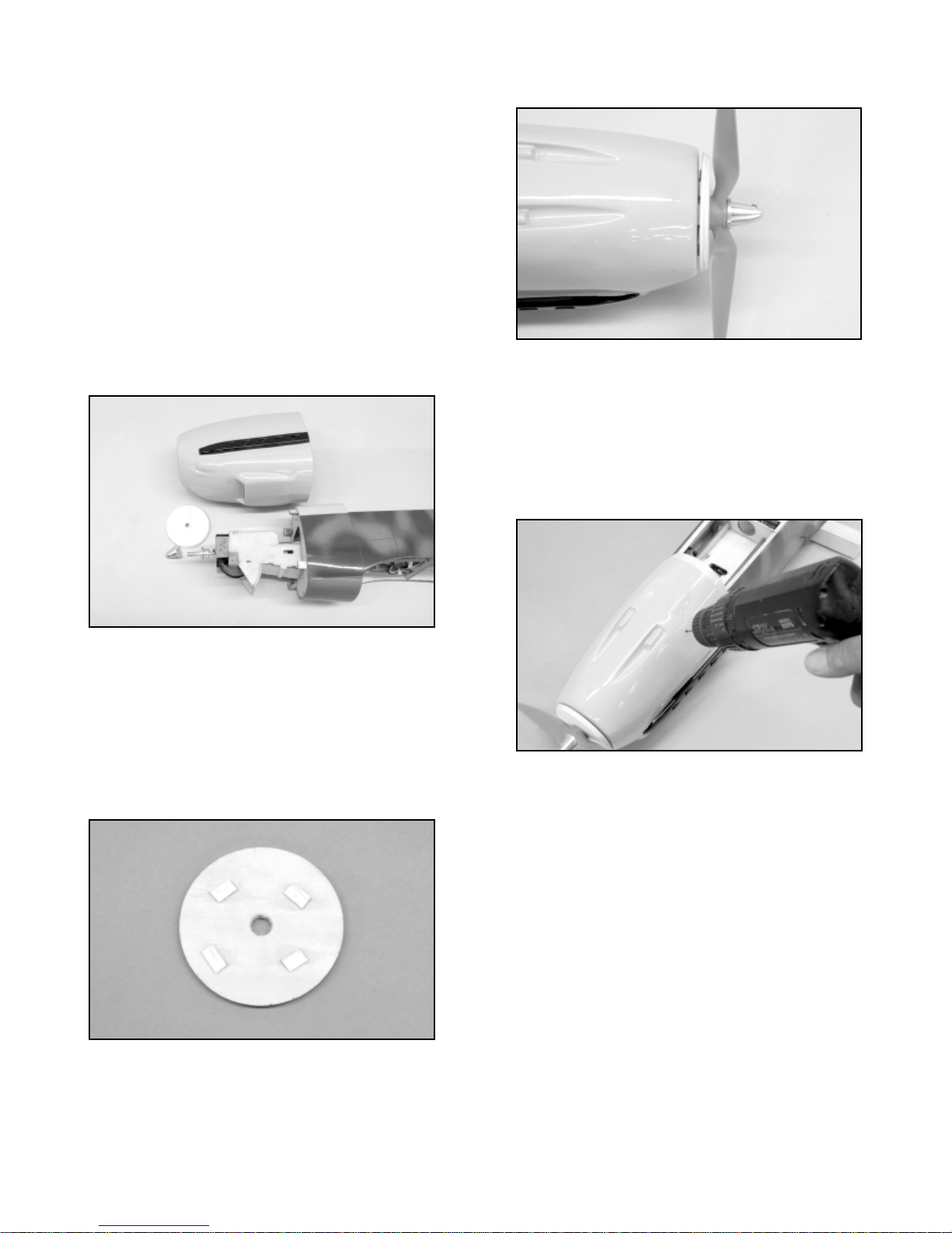
❑ 3) On the bottom rear of the fuselage, measure 2-1/4" (56 mm)
forward from the rudder hinge line and make a mark on each side.
This is where the eye of the brace will be mounted to the fuselage.
Clip the R/C link to the tab on the stabilizer and position the eye of
the brace wire even with the 2-1/4" mark. Use a sharpened awl to
puncture the covering and wood at the center of the eye. Use two
T2 x 8 mm PWA screws to mount the braces to the bottom of the
fuselage. Remove the screws and s wing the braces out of the w a y.
12
hinges and surrounding wood. Once sufficient time has passed,
move the rudder briskly left and right to free up its movement.
❑ 6) The pushrod connections are now made between the
elevators and rudder and their corresponding servos. Starting with
the elevator pushrod, slide a pushrod connector onto the elevator
pushrod wire. Now, install the pushrod connector stub into the last
outer hole in the elevator control horn and secure it to the horn with
the metal cup washer. Repeat this procedure for the rudder
pushrod, installing the pushrod connector stub into the second
inboard hole in the rudder control horn, as shown.
Turn on your transmitter and power up the receiver with your flight
battery pack. Once again, check the rudder and elevator trims,
making sure they are at neutral settings. Hold the elevators in the
neutral position to the horizontal stabilizer, using a couple of small
pieces of tape applied to the outboard hinge lines. With the
elevators now locked in neutral, use a screwdriver to firmly tighten
the setscrew in the elevator pushrod connector. Remove the tape
holding the elevators. Moving to the rudder, again use a piece of
tape to hold the rudder in neutral to the vertical fin. With the
rudder now locked in this position, use a screwdriver to firmly
tighten the setscrew in the rudder pushrod connector. Remove the
tape holding the rudder.
Use the transmitter to now test the movement of both the elevators
and rudder. If the movement of either of these surfaces in the
wrong direction, use the servo reversing function to change the
movement and, if necessary, re-center the surfaces to achieve a
neutral setting.
❑ 7) The excess pushrod wire behind the pushrod connectors
can now be cut off, leaving about 3/16" of wire for any later final
flight trimming purposes.
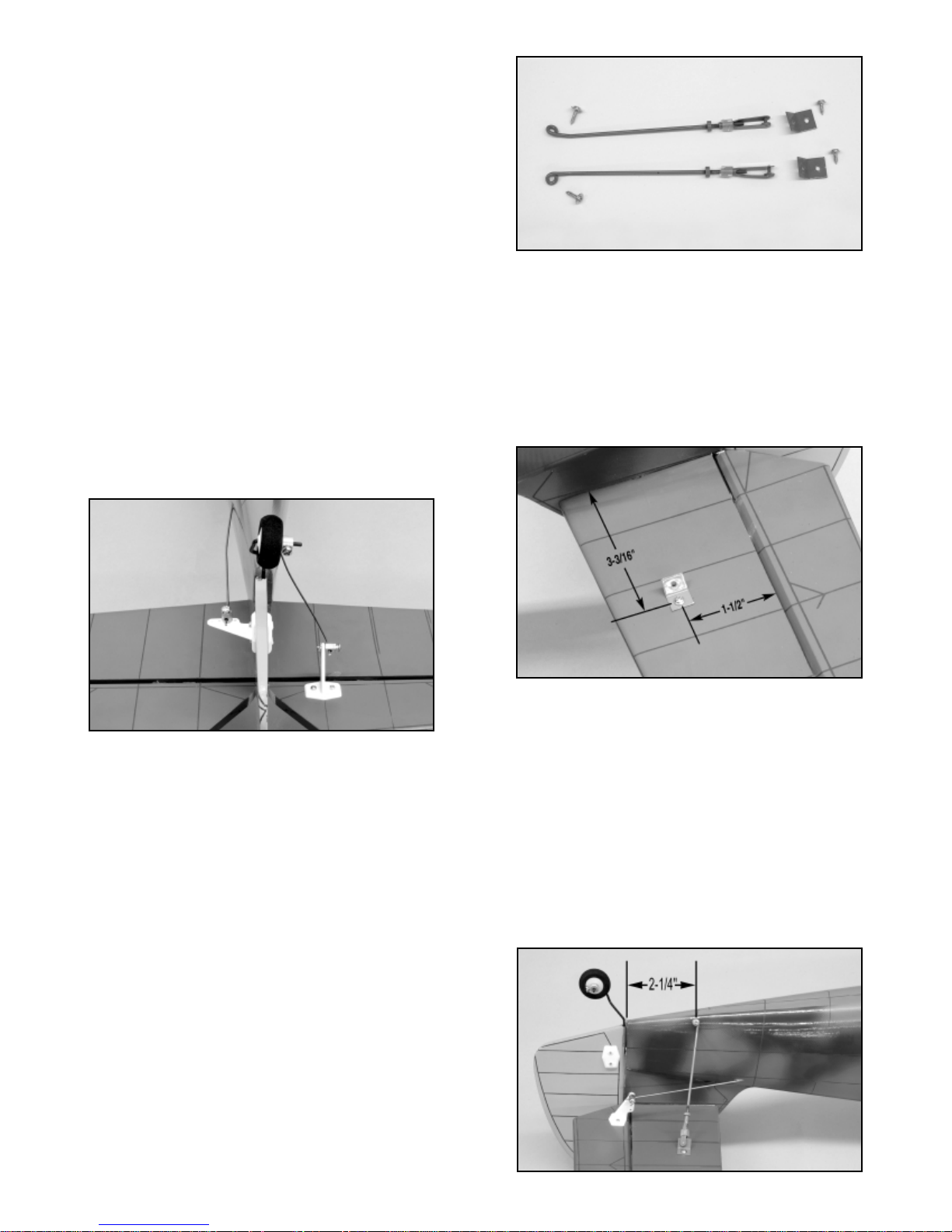
INST ALLING THE T AIL BRACES:
For these steps you will need the following par ts:
❑ Bag #16 2 ea. 2 mm x 94 mm wire tail braces - M2 threads
at one end, bent "eye" at the other end 1 left, 1 right
2 ea. Tail brace mounting tabs - pre-bent
and drilled
2 ea. R/C Links with silicone keepers
2 ea. Knurled lock nuts
2 ea. T2 x 6 mm PWA screws
2 ea. T2 x 8 mm PWA screws

If desired, a functional, scale-like antenna mast can be made using
a 3" (75 mm) length of scrap nylon pushrod tubing, pre-painted
either in gray or flat black. Drill a pilot hole for this antenna mast,
1/2" behind the top rear edge of the canopy, centered on the top of
the fuselage. The antenna mast is now glued into the drilled hole
using 5-minute epoxy glue. The receiver antenna can now be
routed up through the antenna mast tube and extended back to the
top leading edge of the vertical fin where it can be secured with a
small bead-head pin.
Many of us enjoy seeing a pilot figure in the cockpit of our models.
In the case of the Bf-109, this simple addition looks great and
provides a sense of scale and realism to the finished airplane. Our
pilot figure started life as a Williams Bros. 1/6th scale Standard
Pilot figure. After assembling it, we, then, cut down the figure to fit
within the cockpit area. Then, we used plastic paints to add color
and finish to the pilot. We mounted him in place and remounted
the canopy.
Use a fine applicator tip and thin CA to place a drop of glue into the
screw holes in the fuselage to "harden" them. Reinstall the braces
and screws.
FINAL DETAILS:
The canopy is now mounted in place ov er the cockpit. From the kit
parts, locate the canopy and the four T2 x 6 mm PWA mounting
screws. In top view, the canopy is centered over the cockpit with
approximately 1/8" of its rear edge extending back past the rear
surface of the slanted cockpit/fuselage f ormer . Use small pieces of
tape to hold the canopy in this position. Use the four T-2 x 6 mm
PWA screws; threaded through the provided holes in the canopy,
to secure the canopy in this final mounted position. Remove the
tape holding the canopy, and then, remove the four mounting
screws. We suggest using a fine tip applicator with thin CA to
harden each of the screw holes. A single small drop of thin CA
glue, applied directly into each hole will provide hardened threads
for secure mounting.
The simulated supercharger air scoop (Bag #11), located on the
left side of the cowl is now glued in place with the lower front
corner of the scoop 1-1/2" (38 mm) ahead of the back edge of the
cowl and 3/8" (9.5 mm) above the exhaust manifold. T o mount this
part, we used thick CA glue, sparingly applied to the bottom
surface of the air scoop.
If desired, typical plastic paints can be used to add a little more
detail and realism to the cowl. The two machine gun troughs on
top of the cowl can be painted flat gray to simulate gunpowder
staining. The molded gun barrels can be painted flat black. The
two exhaust manifolds can be painted a smoky gray to simulate
burning exhaust.
13
PREP ARING THE SPINNER:
The plastic spinner cone supplied with this kit has a unique shape,
peculiar to the Bf-109 and is supplied uncut. This is to allow the
builder to use it for a 2 or 3 bladed prop for either flying or display.
Finishing this spinner is not difficult but does require some care.
Note that mounting this spinner requires an adapter nut that
threads onto the shaft of your particular motor at one end and is
tapped for an 8-32 bolt on the opposite end. C.B. Associates
makes these adapter nuts in any size that you will need. You will
also need an 8-32 x 3/4" socket head bolt and a several #8
washers for use as spacers.
For the following steps, locate Bag #13 containing the spinner
parts.
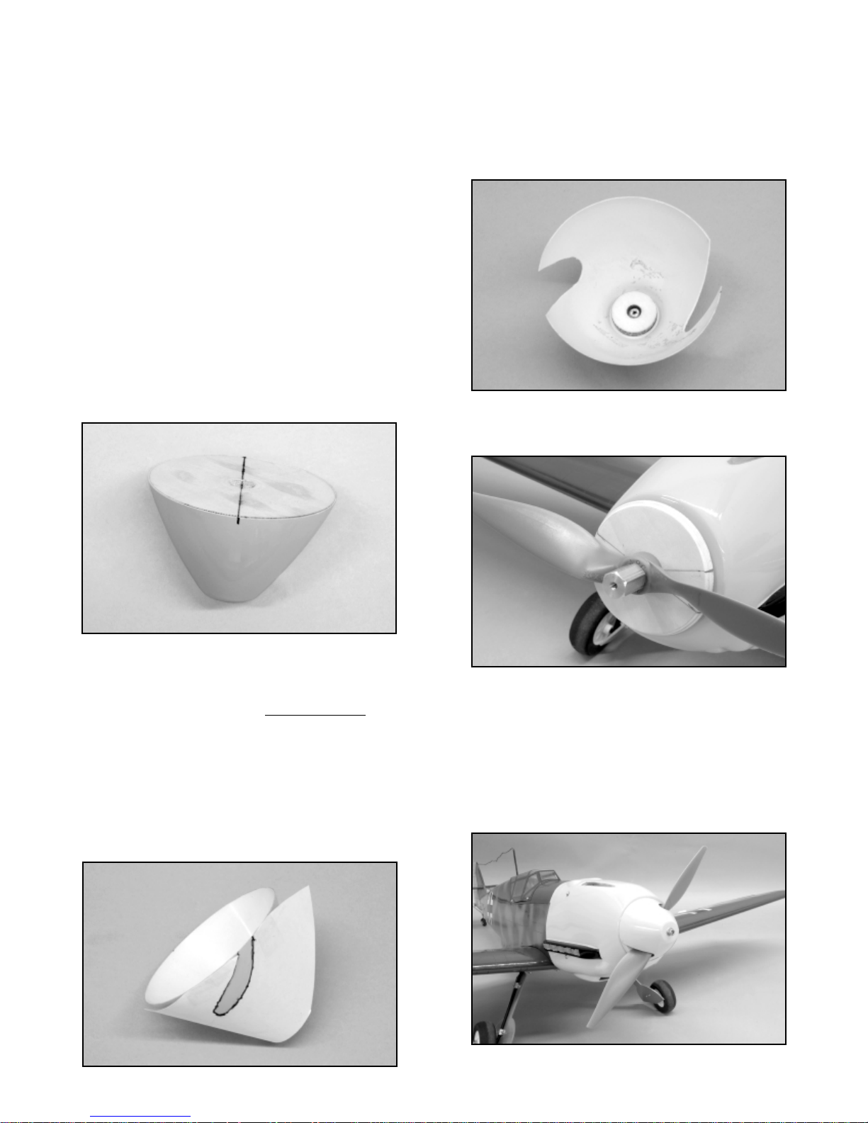
❑ 1) To locate the cutout locations for the blades of a two bladed
propeller, start by drawing a straight line across the bac k surf ace of
the plywood spinner backplate, exactly through the center of the
prop shaft hole. On a flat surface, place and hold the spinner over
the backplate and use a pencil to transfer the two opposing edge
marks onto the back edge of the spinner cone.
Note: If you want to use a three-bladed propeller, use a compass
to make three pencil marks at 120
O
apart.
❑ 2) Cut out the propeller template f
ound on page 16. Align the
leading edge of the template with one of the marks on the edge of
the cone. Tape the template in position and trace the outline of
the blade cutout onto the cone. Move the template over to
the opposite mark, tape it in place and use pencil to trace the
remaining blade cutout outline. The prop blade cutouts are now
made in the spinner. To mak e this relativ ely easy and accur ate , we
used a Dremel
®
Tool with a highly tapered sanding bit, followed by
sandpaper to smooth the edges.
14
❑ 3) Use thick CA glue or 5-minute epoxy to glue the tw o 20 mm
dia. plywood washers together with their center holes aligned.
Glue the laminated 20 mm washer assembly to the inside flat nose
of the plastic spinner, aligning the center hole with the molded
"dimple" on the inside of the spinner. Use thick CA glue or
5-minute epoxy. After the glue sets, use a #19 (.166 dia.) bit to drill
through the front center of the spinner, at the dimple mark.
❑ 4) Place the spinner backplate on the motor shaft and then,
the propeller. Tighten these parts in place with the adaptor nut.
Insert an 8-32 x 3/4" bolt into the front of the cone and place about
4 washers on the bolt on the inside of the spinner.Thread the bolt
into the adapter nut and adjust the number of washers on the bolt
until the skirt of the cone is just even with the bottom of the
plywood backplate when the bolt is tightened down. This spacing
will remain the same as long as you replace the prop with an
identical prop. Changing brands and/or sizes of props will more
than likely change the required amount of shims.

CENTER OF GRAVITY:
Establishing the Center of Gravity (C.G.) for this or any R/C model
aircraft is critical to its ultimate success in the air. And determining
the proper C.G. location becomes even more important with
15
smaller models. While the Bf-109 is a solid, predictable airplane to
fly, it is, none-the-less, a warbird type aircraft and is less tolerant to
improper C.G. locations than other model types.
Start by installing the battery pack that you will be using to power
the airplane. Slide the pack as far forward in the battery tray as
possible and secure it in this position to keep it from shifting while
you are working with the model. Attach the cockpit/hatch over the
battery compartment.
The correct C.G.location for this model is exactly 2-1/2" (63.5 mm)
behind the leading edge, at the fuselage/wing location. Use two
pieces of masking tape, applied onto each side of the top surface
of the wing, where it meets the fuselage wing saddle. Bolt the wing
in place to the fuselage and use a ruler to measure and mark the
2-1/2" location onto the tape, immediately next to the fuselage.
With the airplane now assembled with the battery pack in place, it
is ready for balancing. The best way to do this is to place the model
onto a balancing fixture upside down. Locate the balancing fixture
at the two 2-1/2" marks on each side of the wing, next to the
fuselage sides. If the model is properly balanced, it will be
suspended perfectly level. If the nose hangs down, the air plane is
nose heavy and conversely, if the tail hangs down, the model is tail
heavy. A slightly nose heavy model is certainly the lesser of two
evils. However, a tail heavy condition m
ust be remedied before
flying the airplane.
If your model balances a little nose heavy, the battery pack can be
shifted a little aft to correct the problem. If the model balances in
a tail heavy condition, then, it is likely necessary to modify the
existing battery tray, allowing the flight battery to be shifted even
further forward. As shown with our Himax 400 watt motor
installation, we were able to modify the battery tray, allowing the
battery pack to slide a full 1-1/4" further forward.
Modeler’s Note: A standard 2-3/4" dia. yellow nylon spinner,
such as a SIG # SIGSP2755, can be used to make a nice
looking alternative spinner, by simply cutting off 1/2" from the tip
of the spinner cone.
Once this cut has been made, the cut line should be rounded
off, giving the appearance of the scale opening for the cannon
muzzle. To do this, we used a bolt and a nut as an arbor and
then, installed the end of the bolt in a drill press. With the
spinner turning, sandpaper was used to uniformly and neatly
round off the opening.
The finished spinner should look like the photo.

16
Again, as shown, the battery pack, in place in the battery tray, now
sits directly behind the motor with a piece of scrap 1/4" balsa in
place to keep it from shifting. This "fix" works well when using
lighter motors and is far superior to adding weight to achieve
proper balance.
Once you have achieved the proper 2-1/2" C.G.location by shifting
the battery as needed, mark and note the battery location onto the
battery tray to ensure that it is installed and retained in the proper
position, every time the model is flown.
CONTROL MOVEMENTS:
The Bf-109 is a fighter plane and as such, is designed to be
responsive to your control inputs. It is very important to set your
model up to these recommended throws, for the first flight, to a v oid
any nasty surprises, especially on elevator. Set the throws as
close to these specifications as possible mechanically by moving
the linkages in or out on the servo arms and control horns, then
fine tune these throws with the adjustments available in the
transmitter.
Recommended Initial Contr
ol Movements:
ELEVATORS: 1/2" (12 mm) up and down
AILERONS: 3/8" (9.5 mm) up and down
RUDDER: 7/8" (22.25 mm) left and right
FLYING:
If you have carefully followed this assembly manual, you should
have no real problem test flying your Bf-109. We suggest
choosing a calm day for the first flights. Such conditions always
help in correctly evaluating the flight perfor mance of the model.
If you have built your Bf-109 model without landing gear, the
requirement is, of course, to hand-launch the airplane. The
hand-launch can be done by a friend and, with a little experience,
you can also learn to launch the model by yourself. To properly
hand-launch a low-wing model like the Bf-109, the fuselage is
firmly gripped just behind the wings. The airplane should be briskly
launched straight ahead, directly into the wind, with the wings level
and the motor at high throttle. The launch should be aimed
directly at the horizon - ne
ver hand-launch the model with the nose
up!
If you have built your Bf-109 model with the landing gear, then of
course, the airplane can be taken off from the ground. Ar m the
motor and test the flight controls for correct movement. Hold up
elevator and taxi the model to get a feel for how it handles on the
ground. Make sure you have positive left and right turning ability.
If you don't, make any adjustments needed to achieve positive
ground control. Once you are satisfied with the taxi tests, line the
model up with the center of the runway with the nose pointed
directly into the wind. Hold a little up elevator and smoothly
advance the throttle - do not
throw the throttle fully open all at once!
The model should roll forward smoothly, tailwheel on the ground.
As is typical of this type of airplane, you will need to be ready with
some right rudder as you slowly release the up elevator and allow
the tail to rise. Allow the speed to build until a slight application of
up elevator breaks it free from the runwa y. Do not try to force it into
the air before it is ready to fly.
Once the airplane is airborne, maintain a straight outward flight
path, climbing at a shallow angle, until a safe maneuvering altitude
is reached. If the model requires trim input, fly to a reasonable
altitude before attempting to make any changes. Make your
control inputs smooth and avoid jerking the sticks. At trimming
altitude, bring the throttle back to about a 2/3rds setting for cruise
speed and then, begin fine-tuning any required trims. What you
want to achieve is a straight and level flight path without
transmitter corrections.
Once you're comfortable with the way the model is flying, make a
few circuits around the field, getting a feel for the controls. If the
airplane is properly trimmed, it should demonstrate smooth flight
characteristics, without any jumpiness or over sensitivity. At
altitude, try an axial roll. Next, try another roll in the opposite
direction. The Bf-109 should roll smoothly in each direction. Next,
try a simple inside loop. Choose your entry heading and go to full
throttle. Pull up smoothly until the airplane is inverted, then back
off the throttle as it comes down the backside of the loop.
Consecutive loops are easily done using the same technique. This
maintains a steady airspeed and conserves battery power. Still at
cruise speed and reasonable altitude, roll the model inverted. A
properly balanced model will take very little down elevator to
maintain inverted flight.
By now, you should be getting comfortable with the handling of
your Bf-109. Fly the airplane up to a safe altitude, flying directly
into the prevailing wind. Throttle back the motor to become
familiar with the slow flight characteristics of the model. Still at a
lower throttle setting, make a few dummy landing approaches,
Spinner Template
17
including the required turns. What you're looking for is a
comfortable landing speed. Now, try a fe w po wer-on and po wer-off
stalls. Again, you're looking for the speed at which the model stalls
and also for the type of stall that will occur. All of this is great
information to have when you are setting up your first landing.
After making a few high-speed strafing passes over your field, it's
likely time to set-up your Bf-109 for a landing.
We always suggest that you make your landings using a standard
approach. Enter the downwind leg at about 50' in the air, throttled
back just enough to allow the airplane to very gradually sink. Make
the base turn, followed by the final turn, lined up with the center of
the runway. Keep a little power on the model, while keeping the
nose just slightly down. Fly to the touch down location until the
model is a foot or so off the ground. Start easing off of the throttle,
allowing the airplane to touch down on the main wheels. Allow the
tail wheel to settle to the ground and let the model finish its rollout
to a stop. Hold full up elevator and taxi bac k to the pits . With some
experience, you'll be making ver y nice landings every time.
With the first flight now in your logbook, it is time to completely
check ever ything in and on the model that may have come loose
or needs attention. In our long experience with model aircraft,
we've learned that anything that might come loose or needs
attention, will show up within the first few flights. Do yourself a
favor and check everything now. The second flight should be even
more fun because you now have a tr immed model.
MAINT AINING YOUR Bf-109:
Getting into the habit of routinely performing maintenance and
inspection of your Bf-109 will keep it looking good and flying good
for a long time. Full scale airplanes receive this kind of routine
treatment and fly safely for years. Your R/C model aircraft should
receive the same treatment.
After each flying session take the time to completely clean your
model. If you are used to cleaning up glow powered models, you
should really enjoy how easy it is to clean up an electric model! W e
use and suggest fresh, good quality paper towels and a silicone
free cleaner for degreasing and polishing. SIG makes one of the
best cleaners for this purpose - Pure Magic Airplane Cleaner.
Clean the airplane until it shines including the prop and spinner.
At home take a little time to completely inspect the airplane,
looking for loose bolts, screws , co vering seams, etc. Anything that
you find wrong - immediatel
y fix it! Inspect the fuselage radio
compartment carefully. Check each servo, looking for loose
linkages, missing screws, etc. Check each R/C link for integrity
and to make sure the keepers are in place. Check all the control
horns and servo arms to be sure they are firmly attached to the
control surfaces.
Finally, after each flying session you should monitor the charge on
your radio system, charging it as needed. If several days pass
before you fly again, top off the charge bef ore flying again. Be sure
that the radio is fully charged before heading out to the flying field
again.
Good luck and good flying.........
Messerschmitt Bf-109 Log Book
Date of first flight:
Comments:

18
LIMIT OF LIABILITY
The craftsmanship, attention to detail and actions of the builder/flyer of this model airplane kit will
ultimately determine the airworthiness, flight performance, and safety of the finished model. SIG MFG. CO.’s
obligation shall be to replace those parts of the kit proven to be defective or missing. The user shall
determine the suitability of the product for his or her intended use and shall assume all risk and liability in
connection therewith.
CUSTOMER SERVICE
SIG MANUFACTURING COMPANY, INC. is committed to your success in both assembling and flying the
MESSERSCHMITT Bf-109 ARF kit. Should you encounter any problem building this kit, or disco ver any missing or damaged parts, please feel free to contact us by mail or telephone.
SIG MANUFACTURING COMPANY, INC.
P.O. Box 520
401-7 South Front Street
Montezuma, IA 50171-0520 USA
PHONE: 1-641-623-5154
FAX: 1-641-623-3922
SIG WEB SITE: www.sigmfg.com
SIG E-MAIL: mail@sigmfg.com
WARNING! THIS IS NOT A TOY!
Flying machines of any form, either model-size or full-size, are not toys! Because of the speeds that
airplanes must achieve in order to fly, they are capable of causing serious bodily harm and property
damage if they crash. IT IS YOUR RESPONSIBILITY AND YOURS ALONE to assemble this model
airplane correctly according to the plans and instructions, to ground test the finished model before each flight
to make sure it is completely airworthy, and to always fly your model in a safe location and in a safe
manner. The first test flights should only be made by an experienced R/C flyer, familiar with high
performance R/C aircraft.
The governing body for radio-control model airplanes in the United States is the ACADEMY OF MODEL
AERONAUTICS, commonly called the AMA. The AMA SAFETY CODE provides guidelines for the saf e operation of R/C model airplanes. While AMA membership is not necessar ily mandatory, it is required by most
R/C flying clubs in the U.S.and provides you with important liability insurance in case your R/C model should
ever cause serious property damage or personal injury to someone else. For more information,
contact:
ACADEMY OF MODEL AERONAUTICS
5161 East Memorial Drive
Muncie, IN 47302
Telephone: (765) 287-1256
AMA WEB SITE: modelaircraft.org

 Loading...