


LIL’ RASCAL ARF ASSEMBLY MANUAL
INTRODUCTION:
Congratulations on your purchase of the SIG Lil’ Rascal ARF kit!
The SIG Rascal series have become popular with modelers
because their classic looks and good flying characteristics. SIG is
pleased to now offer this same fine design in this unique 180 class
size. The Lil’Rascal ARF not only retains the great characteristics
of the original but is also small enough to take almost anywhere,
completely assembled and ready to fly! Unlike most other small
electric powered models, the Lil’Rascal has a really nice po wer-toweight ratio, allowing it to handle much higher wind conditions.
Your Lil’ Rascal ARF has been expertly covered with Oracover
®
.
This covering material is tough and light weight and is easily
repairable. This kit has been specifically engineered to make
assembly fast and simple when following the detailed instructions
in this manual.
The Lil’ Rascal ARF is very light and therefore well matched to the
included electric 180 class motor and geardrive unit. This power
system swings the supplied 6 x 4 prop with amazing power and
efficiency. There are quite a few micro electronic speed controllers
(ESC) that will work well in this model, in the 4-10 Amp range. The
ESC unit shown in this manual is the MAXX Products MX-9104
ESC. This is a very small, light weight 4 Amp unit that handles
5-7 cell battery packs and includes a battery elimination circuit
(BEC), doing away with the need for a separate receiver battery.
This unit is available from MAXX Products, already pre-wired with
the appropriate JST connectors.
To maximize the performance of the motor/geardrive unit used in
this model, we suggest using a 7-cell 300 mAh Ni-MH (2/3 AAA
size) battery pack, in a “folded” configuration. Properly charged,
this pack delivers excellent power and great duration for the Lil’
Rascal model. To derive the maximum capacity and performance
from your battery pack, it is essential to use the correct battery
charger. We use and highly recommend a charger that is designed
for charging NiMH cells, such as the Astro Flight #115D unit. This
charger is an AC/DC type, allowing you to charge packs either at
home or from your car’s 12-volt batter y at the field. It is also a
“Peak Delta” charger, assuring a maximum battery pack charge
every time. Using this charger, at a 1 Amp charge rate, our packs
take about 15 minutes to fully charge. Having at least two battery
packs will allow you to fly almost continuously.
The assembly and flying of this model will only be successful if you
follow these instructions carefully. Deviating from these
instructions has the potential to cause problems later in the
assembly process or during flight. The successful assembly and
flying of this model is your responsibility so take your time and
enjoy your Lil’Rascal.
RADIO EQUIPMENT:
The Lil’ Rascal ARF gets its performance from many factors, such
as its light weight and generous wing area. These combine to
produce a very favorable wing loading, allowing the model to take
advantage of the 180 motor/geardrive unit. Since this model is
factory built and covered, you can only realistically control the
finished, ready-to-fly weight by choosing the most appropriate
radio equipment for a model of this size. In short, the performance
of the Lil’Rascal will be reflected in the equipment that you choose.
In flight tests of the Lil’ Rascal, we used the Hitec™ #HS-55
servos. However, any brand of servo that is in the same size and
torque range as the HS-55 servo will work just fine. For example,
one of our test models used the MAXX Products MX-50 units and
they performed perfectly. In general, the servo torque proper ties
for the Lil’Rascal ARF model should be in the 9 – 14 in./oz. area.
Only small or “micro”receivers should be used in this model due to
weight and size constraints. We prefer to use dual conversion
receivers, such as the Hitec™ Electron 6, the FMA M5, etc. Single
conversion receivers can also be used as long as y ou are a w are of
the potential for interference from other transmitters. When we
used the Hitec™ Electron 6 receiver, we carefully removed the
plastic case, thus saving another 7 grams (about 1/4 oz.) in weight.
As mentioned earlier, you will also need a 4-10 Amp electronic
speed controller (ESC) to control the throttle function. Your
ESC should be pre-wired with JST connectors in order to connect
properly with the motor connector.
In general, choose your airborne radio equipment carefully. As
with any airplane, especially electric powered models, excess
weight is to be avoided. Maximum performance can only be
achieved with light weight components.
COVERING MATERIAL:
Your Lil’ Rascal ARF has been covered using Oracover
®
. This
material is world famous for its ease in application, light weight,
and consistent color. If you live in a dry climate, you may notice
some wrinkles develop in the covering after you remove the
covered parts from their plastic bags. This is perfectly normal in
low humidity. The model was covered in a part of the world where
the relative humidity is high and some of this moisture is retained
in the balsa wood. When the covered parts are exposed to drier
humidity conditions, the retained moisture will evaporate causing
1
R
the wood to dimensionally “shrink”in the process. In turn, this may
cause some relaxing of the covering. However, this is easily taken
care of using a small heat iron, such as a small “trim seal”type unit.
When using a larger iron, we suggest using a “sock” of thin cloth
over the shoe to avoid scratches. The iron should be set to about
280
O
- 300OF. Use the heated iron over the wrinkle to lightly shrink
the material – do not press on it. Then lightly iron it back down to
the wood. The use of a heat gun is not recommended since the
parts are really too small. Avoid contact with the plastic windows
and windshield because the heat will distort the plastic.
Over-heating the covering seams may cause them to shr ink too
much and possibly expose the wood beneath. For this reason, we
don’t suggest using a heat gun. A typical hobby type covering iron
will work just fine on a model of this size. A small “trim seal” iron
is perfect for controlling the heat applied to a specific area. Using
such an iron also minimizes the possibility of warping the thin
parts.
For part number reference, your Lil’Rascal is covered in Oracover
®
film with the following part numbers: #10 White, and #21-29
Transparent Red, or #21-59 Transparent Blue.
REQUIRED TOOLS:
For proper assembly, we suggest you have the following tools and
materials available:
• A selection of glues - SIG Thin and Thick CA
and SIG Kwik-Set 5-Minute Epoxy
• CA applicator tips - fine
• Screwdriver Assor tment
• Pliers - Needle Nose and Flat Nose
• Wire Cutters
• Pin Vise for small diameter drill bits
• Small T-pins
• Sandpaper
• Hobby Knife with sharp #11 blades
• P aper Towels
• Small W eights
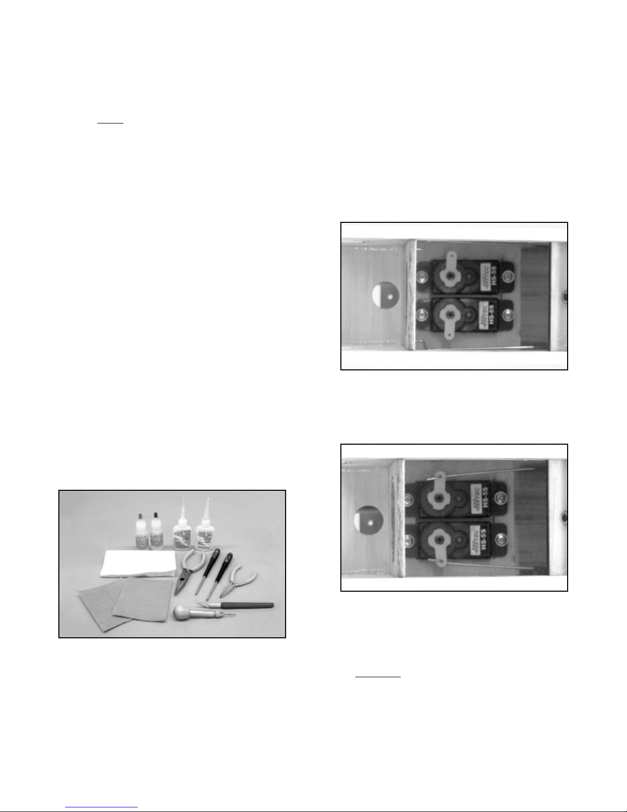
FUSELAGE:
The fuselage is essentially complete with the wire rudder and
elevator pushrods already in place. All that is required is the
installation of the rudder and elevator servos and connecting the
servo output arms to the “Z” bends on the pushrods. For this step
you will need the two required servos and the mounting screws
that came with them. Remove the servo output arm retaining
screws and the output arms from the two servos.
The rudder and elevator servos are now installed into the fuselage,
from the top. First remove the battery hatch from the bottom of the
fuselage. Position the servos in place into the servo tray. Drill
small pilot holes for each servo screw using a pin vise and small
drill bit - we used a .040” (#60) drill bit for these pilot holes. Use a
small Phillips screwdriver to install the servo mounting screws all
the way. Now remove the screws and the two ser vos. Apply a
single drop of Thin CA glue to each screw hole and allow the glue
to set. Re-install the servos and their mounting screws into the
servo tray. From the bottom battery tray opening, route the two
servo leads out of the servo compartment and up through the rear
hole in the receiver mounting tray.
Test fit the two servo output arms onto each servo, positioned at
90
O
to the servo body. If these ar ms interfere with each other, trim
them accordingly.
Remove the servo arms. Attach the wire elevator and rudder
pushrods to the ends of each output arm. Place the arms back
onto the servo output shafts and re-install the output arm screws do not tighten these yet because they may have to be repositioned
when the radio system is tested and centered.
MOUNTING THE T AIL GROUP:
❑ 1) From the kit contents locate the horizontal stabilizer and
elevator and the ver tical fin and r udder. Also locate the two white
plastic control horns. NOTE: As received, the elevator and rudder
are only tempor
arily attached to the stabilizer and fin with unglued
CA hinges in the pre-cut slots. Remove the elevators from the
stabilizer and the rudder from the fin. Also remove the hinges from
them.
2

❑ 2) Before hinging the elevators to the stabilizer, glue the white
plastic elevator control horn in place, using Thick CA glue. Apply
a small amount of glue to the two “spikes”on the base of the horn
and a small amount of glue to the base itself. With the three small
holes in the control horn facing forward, firmly press the horn
into the two pre-drilled holes at the leading edge of the elevator
assembly, until the base bottoms out on the elevator surface . If any
glue oozes out onto the covering, it can be quickly removed with
SIG CA Debonder.
❑ 3) The elevator assembly is now hinged to the horizontal
stabilizer. Insert the four (4) CA hinges half way into the pre-cut
hinge slots in the leading edge of the elevators. Once the hinges
are in place, use a small T-pin through the center of each hinge to
keep them from being pushed back any further into the elevators.
Insert the exposed ends of the hinges into the pre-cut slots in the
horizontal stabilizer - NOTE: Properly in place, the elevator
horn will be on the left
side of the stabilizer. Move the elevator
assembly left or right as needed to center it with the horizontal
stabilizer. Use a piece of tape to hold the elevators in the full
“down” position. Remove the pin from one of the hinges and use
Thin CA glue, with a fine applicator tip, to apply 2-3 drops to the
exposed center of the hinge. Remove the pin from the next hinge
and again, apply 2-3 drops of glue to the exposed center of the
hinge. Repeat this process with the remaining two hinges.
Remove the tape holding the elevator in the down position,
allowing it to center itself with the stabilizer . Turn the stabilizer over
and again, use a piece of tape to pull and hold the elevators in the
full “up” position. Apply 2-3 drops of glue to each exposed hinge
center and remove the tape. Allow about 10 minutes for the glue
to fully wick its way into the hinges.
After the glue has set, firmly flex the elevators full up and down to
free their movement, removing any “stiffness” to their action.
❑ 4) The horizontal stabilizer/elevator assembly is now glued to
the fuselage. To allow a little time to work and properly align the
stabilizer, use SIG 5-Minute Epoxy for this step.
Begin by first mounting the wing to the fuselage using the
provided 4-40 nylon bolt. Place the model onto a flat surface that
lets you view it directly from the front. Prop-up the rear of the
fuselage with scrap wood to allow the tail wire to clear the surface.
Mix and apply a small amount of epoxy glue to the exposed wood
on fuselage stabilizer saddle area. Carefully place the stabilizer on
the fuselage saddle area, centering it as close as you can. Wipe
off excess glue using alcohol and towel. Use a small weight to hold
the stabilizer firmly to the fuselage. View the model from the front
to see if the stabilizer is squarely in place in relationship to the
wing/fuselage, without tilting to one side or the other. Make any
adjustments needed to hold the stabilizer in this correct position.
Now view the stabilizer from the top to make sure it is in place with
its trailing edge square to the fuselage. Allow the epoxy to cure
completely.
❑ 5) The vertical fin - without the r
udder hinged in place - is now
glued to the top of the stabilizer, again using SIG 5-Minute epoxy.
First, trial-fit the fin into the slot in the top of the stabilizer, without
3
X
X = X
O
O
90
90
X
X
X

any glue. If needed, trim the bottom fin tab to allow full contact of
the fin base to the top of the stabilizer and the fuselage. Have the
wing mounted to the fuselage and sitting on a flat surface to allow
easy viewing from the front. Prop-up the rear of fuselage to clear
tail wire. Mix and apply a small amount of glue to the bottom edge
of the fin and the sides of the locating tab. Carefully press the fin
into place. Wipe off any excess epoxy using alcohol and towel.
Viewing the model from the front, make sure that the fin is 90
O
to
the horizontal stabilizer. Viewing the model from the side, the
trailing edge of the fin should line-up with the very rear of the
fuselage. Use tape to hold the fin in place and let the glue set.
After the glue sets remove the tape and the wing from the
fuselage.
❑ 6) Prepare the rudder for hinging by first installing the
remaining white plastic control horn on its lower r
ight side, in the
two pre-drilled holes. Apply a small amount of Thick CA glue to
the “spikes” on the horn’s base and a small amount of glue on the
base itself. Press the horn firmly into the two holes until its base
bottoms out on the surface of the rudder.
Using the three (3) remaining CA hinges, insert them half way into
the rudder. As you did with the elevator hinges, use a T-pin through
each hinge at the center. Inser t the exposed hinge ends into the
slots in the fin and fuselage. Make sure the rudder clears the fin
at the top and aligns with the fuselage at the bottom. Use a piece
of tape to hold the rudder in the full “right” position. Remove the
pin from one of the hinges and use Thin CA glue to apply 2-3
drops at the exposed center of the hinge. Repeat this process with
the remaining two hinges. Remove the tape holding the rudder,
allowing it to return to its neutral position. Use a piece of tape to
hold the rudder in the full “left” position and again apply 2-3 drops
of glue to each exposed hinge center. Remove the tape and allow
about 10 minutes for the glue to set. Fir mly flex the hinged rudder
back and forth until its movement is free and easy.
LANDING GEAR:
❑ 1) Locate the 2 main wheels, 2 wheel pants – 1 left, 1 right,
2 plastic retaining pads, and the pre-bent wire landing gear.
❑ 2) Look at the landing gear and the wheel pants. Understand
that when assembled, the wheel pants face forward while the
V-bend shape at the top center of the landing gear wire points to
the back of the fuselage.
❑ 3) Insert the wire landing gear axle wire just into the hole in the
plastic wheel pant, the side with the molded wire recess. Slip one
of the wheels into the wheel pant and feed the wire axle through
the wheel axle hole. Once the wire is through the wheel, you can
feed it through the hole in the outer side of the wheel pant.
❑ 4) Locate one of the square plastic retaining pads. Use sand
paper to rough up one side. Apply a small amount of Thick CA
glue to the roughened side of the pad and place it, centered over
the wire landing gear, against the wheel pant surf ace. Hold in position until the CA sets. Repeat this process to finish the remaining
wheel pant/wheel assembly.
❑ 5) Attach the assembled landing gear to the fuselage bottom
using the two M2 x 6MM screws supplied. Insert the screws
through the metal brackets and into the two pre-drilled holes. Use
a small Phillips screwdriver to secure the landing gear to the
fuselage.
RADIO INSTALLATION:
For the following steps you will need your micro receiver, a
micro 4-10 Amp ESC with the proper connectors, your charged
transmitter, and a charged battery pack.
4
MODELERS TIP: A real problem with smaller R/C models is
the typical length of the receiver antenna. These are often 30”
to 36” long and therefore leave a great deal of their length
hanging off the rear of a small model, such as the Lil’ Rascal.
Because the antenna should never be cut, the only other way
is to shorten its length using a “bobbin”. We have used this
technique with our own Lil’ Rascal models with excellent
results.

❑ 1) Mount the receiver to the built-in receiv er tra y in the fuselage ,
ahead of the servo compartment. The easiest and lightest way to
mount the receiver is to use a 1”square piece of Velcro
®
tape. The
receiver is mounted between the forward and rear wir ing access
holes in the receiver tray. Position the receiver with its servo
connectors toward the rear of the fuselage cabin.
Earlier, you routed the rudder and elevator ser vo leads up through
the rear hole in the receiver tray. Connect these two leads to the
appropriate rudder and elevator positions in your receiver. The
receiver antenna is routed down through the forward hole in the
receiver tray, into the lower battery compartment. If you used an
antenna bobbin as earlier described, use a piece of tape to hold it
in place against the fuselage side and route the rest of its length
back up through the rear hole in the receiver tray.
❑ 2) To route the antenna out of the fuselage, drill a small 3/64”
dia. hole through the right fuselage side, just below the wing
saddle and just in front of the fuselage former separating the servo
and receiver compartments. Pull the antenna through this hole.
To hold the antenna in place at the rear of the fuselage, use a pair
of needle nose pliers to make a small hook, with a loop at one end
- a piece of straight pin works great. Glue the hook to the rear of
the fuselage, beneath the stabilizer, using a little thick CA. Use a
small rubber band to attach the antenna to the wire hook to hold it
tight.
❑ 3) The electronic speed controller (ESC) is connected to the
motor using a JST connector and simply floats free in the nose of
the fuselage. DO NOT wrap the ESC in foam, plastic, etc. It can
get warm during operation and must be fully exposed to allow it to
stay relatively cool. The receiver connector on the ESC is routed
up through the front hole in the receiver tray and plugged into the
receiver’s throttle position.
❑ 4) The battery pack is mounted to the bottom of the receiver
tray, using the supplied Velcro
®
tape. This makes the battery pack
easy to remove for charging between flights.
The airborne radio system can now be tested for proper operation
– note that the propeller and spinner are NOT yet installed. Note
that in the interest of minimizing weight and in consideration of the
small amount of available space, this installation does not include
an “on/off” switch. Turning the airborne radio system on or off is
simply done by plugging the battery pack into and out of the ESC
battery connector.
a) Make sure your transmitter rudder and elevator trims are in
neutral and that the throttle stick is in the full “low throttle” position.
Turn on your transmitter.
b) Make very sure of the correct polar ity of the connectors and
plug your charged battery pack into the correct battery connector
on the ESC unit.
c) You should now be able to move the rudder and elevator
controls to check for the correct direction of their movement. You
should now also be able to mov e the throttle stick to w ard the “high”
position and the motor should run. NOTE: Some ESC units must
first be “armed” by movement of the throttle stick – read the
manufacturer’s directions for this information.
d) With the system now working, you must check the rudder
and elevator servos for correct movement. Use the servoreversing feature on your radio system, if needed, to make the
servo move in the correct direction.
e) Reposition the servo output arms on the servos as close to
90
O
to the servo case as possible. Reinstall the servo output arm
screws in both servos.
5
The “bobbin” itself is nothing more than a piece of
3/32” x 1/2” x 3/4 ” balsawood. From the receiver, measure the
antenna out to 4-1/2”– no closer. This is the point to start
wrapping the antenna wire around the bobbin. Do not cross
the wrapped antenna wire, simply lay it neatly next to each
strand. Wrapping the antenna wire 12 to 14 times around this
size bobbin, shortens its overall length by about 11”. Hold the
now-wrapped antenna wire to the bobbin with a length of clear
tape. Now when you install the receiver into the fuselage, you
will have a much more reasonable length of antenna wire to
work with at the rear.
What will this procedure do to the range of your receiver? The
answer is that you will lose some amount of range but not
enough to effect the overall safe operation of the model. This
is because a small R/C model is rarely flown to extreme
distances for the simple reason that you can no longer see it.
Since you would nev er do this, some loss of r ange is more than
acceptable for a small model.

f) Now make sure the motor shaft is moving in the correct
direction. When viewing the fuselage from the rear to the front -as if you were sitting in the cockpit -- the motor shaft should turn
clockwise when throttle is applied.
e) At this point, the servo output arms should now be centered,
the servos should be moving in the correct directions and the
motor should be turning in the correct rotation.
❑ 5) The wire pushrods are now connected to the rudder and
elevator control horns. First turn on the transmitter and then plug
the charged battery pack into the ESC connector. Use small
pieces of tape to hold the rudder and elevators in the neutral
position to the vertical fin and the horizontal stabilizer.
❑ 6) Locate the two (2) white plastic pushrod keepers from the kit
contents. Slide one of these keepers onto the wire rudder
pushrod, sliding it all the way to the fuselage side. Now hold the
pushrod wire against the side of the rudder control horn and use a
fine tip marker pen to mark the exact position of the rudder horns
hole on the wire.
Use a pair of pliers to firmly hold the pushrod wire exactly at the
mark just made and bend the wire straight down at a 90
O
angle.
The excess pushrod wire is now removed, leaving about 1/4” of its
length to pass through the control horn hole – use a good pair of
wire cutters to do this. The bent end of the pushrod wire is now
inserted into the hole in the control horn. Slide the plastic pushrod
retainer out to the control horn and press its tab end over the
exposed wire on the opposite side of the control horn.
❑ 7) Using the same technique described above, bend, cut,
and secure the elevator pushrod to the elevator control horn remember to first slide the remaining white plastic pushrod keeper
onto the pushrod wire.
❑ 8) Remove the pieces of tape holding the rudder and elevator
in the neutral position. Now test the action of the rudder and
elevators with your transmitter. If necessary, use the rudder and
elevator trims to adjust the surfaces back to neutral.
❑ 9) The suggested initial control throws are now set for the
rudder and elevator. Most modern radio systems allow you to set
the total movement of the servos directly from the transmitter. This
is usually referred to as EPA, or end point adjustment. You can use
this feature to now adjust the control mov ements f or the rudder and
elevators. The following control movements are recommended for
initial flights. These measurements are taken at the widest part of
the elevators and rudder, at their trailing edges. Later, when you
are more comfortable with the Lil’ Rascal ARF and how it flies,
these control throws can be increased to suit your needs.
RECOMMENDED INITIAL CONTROL THROWS:
Rudder: 1/2” left and 1/2” right
Elevator: 1/2” up and 1/2” down
MOUNTING THE PROPELLER AND SPINNER:
IMPORTANT NOTE: The propeller and spinner assembly
supplied in this kit was expressly designed for use with electric
power systems. These components are not designed for use with
internal combustion engines. Under no circumstances should
these units be used with internal combustion engines because
they may fail and cause ser ious damage.
❑ 1) Locate the propeller and spinner assembly from the kit
contents. These are the black nylon propeller, the white plastic
spinner cone, the spinner backplate, the threaded aluminum collet,
the propeller nut & washer, and the spinner bolt.
❑ 2) Press the aluminum collet firmly onto the motor output shaft
at the front of the fuselage until it bottoms out. Slide the spinner
backplate onto the threaded end of the collet, as far back as it will
go. Slide the propeller onto the collet, back to the backplate. Install
the washer onto the collet and thread the nut onto the collet
threads. Align the propeller between the recesses in the spinner
6

backplate and lightly tighten the nut with finger pressure to hold
the propeller to the backplate. Place the spinner cone in place,
aligning the ridges in its edges with the recesses in the backplate.
Adjust the propeller position as needed to allow the spinner cone
fit in place into the backplate. Remove the spinner cone and use
a small wrench to tighten the propeller nut firmly to the backplate.
This also pulls the collet into the backplate, securing it to the motor
shaft. Place the spinner cone back in place, pressing its locating
ridges into the recesses in the backplate and secure it to the collet
with the spinner bolt.
❑ 3) IMPORTANT: With the propeller now mounted to the motor,
it is v
er
y important that you always remain aware of the position of
the throttle stick on your transmitter. Under no circumstances
should you hold this model by the nose when the radio system
is turned on. The motor/geardrive unit used in this model is
relatively powerful and can cause damage if it is running and
should come in contact with people, property, etc.
DECAL APPLICATION:
The decals supplied with the Lil’ Rascal ARF are high quality
Mylar
®
with an extremely aggressive adhesive. These are not
die-cut and must each be cut from sheet with a hobby knife and a
sharp #11 blade or with sharp scissors.
The small decals can easily applied to the model using tweezers
and finger pressure to set them. For the larger decals, such as the
door outline and the ”Lil’ Rascal” wing decal, we suggest the
following method to accurately apply them. Carefully cut out the
decal with a hobby knife . Lift it carefully off its sheet with tweezers.
Use a product like SIG Pure Magic Model Airplane Cleaner,
Fantastic
®
, or Windex®to spray the area of the model that will
receive the decal. Then spray the adhesiv
e side of the decal as
well. Lightly position the decal in place on the model. The liquid
cleaner allows the decal to slide easily into the desired position do not press down on the decal. Once in position, hold the decal
lightly in place with your finger and use a paper towel to gently blot
the excess liquid awa y. Use a small squeegee to now set the decal
in place, removing all excess liquid and any air bubbles. The SIG
4” Epoxy Spreader - #SIGSH678 - is perfect for this job. Blot up
any excess cleaner with a dry cloth and allow the decals to set
overnight. They will be solidly adhered to the model without any air
bubbles.
BALANCE:
IMPORTANT: The flight pack battery must be installed in the
fuselage and the propeller and spinner mounted in place to the
gearbox when setting up the correct Center of Gravity (CG)
location.
The correct CG location for the Lil’ Rascal ARF is located
precisely at the main spar. This means that when you place you
fingers, one on each side of the bottom of the wing, at the main
spar location, the airplane must balance in a level position. If the
nose hangs low, the model is “nose heavy”. If the tail hangs low,
this means that the model is “tail heavy”. If either of these
conditions exists, you must make adjustments to correct the
problem. Never attempt to fly your model in an out of balance
condition. Since the flight battery pack is the single heaviest
component in the airplane, it can be used to adjust almost any tail
heavy or nose heavy condition. This is simply done by moving the
battery forwards or backwards.
PRE-FLIGHT NOTES:
Be sure your flight battery packs are fully charged or that you take
your 12-volt battery charger to the field with you. Also, be sure
your transmitter is fully charged. We highly recommend that you
perform a standard range check of your radio system - with and
without the motor running. Any problems you have will not
magically disappear at the field! Make sure your propeller is
balanced and has no nicks or cracks - never fly with a faulty
propeller! Finally, take a few minutes to make sure that you go
through your model to make sure ever ything is secure and tight.
FLYING:
If you are new to the hobby/sport of flying R/C model airplanes, DO
NOT attempt to fly this model by yourself! There are hundreds of
AMA (Academy of Model Aeronautics) chartered R/C clubs in the
U.S. The easiest way to find flying clubs in your area is to ask your
hobby retailer. AMA chartered clubs often have qualified
instructors who can teach you how to fly and perhaps even test fly
your model for you. If you are already an R/C pilot, then you will
likely have no problems at all with flying the Lil’ Rascal ARF.
Choose a calm day with little or no wind for the initial flights. This
is important in getting the model properly trimmed. We also
suggest that for the first few familiarization flights, you have a
buddy hand-launch the model. When hand launching, the airplane
must be launched straight and level directly into the wind, with the
nose aimed at a point on the ground about 75’ in front of you.
Never launch the model with the nose pointed up or the wings
tipped to one side or the other. The launch should be firm enough
to achieve flight speed but yet not overly hard. Later, when you’re
more familiar with the airplane and how it flies, you can perfor m
R.O.G.(Rise Off Ground) takeoffs from smooth surfaces.
With a fully charged 7-cell battery pack, your Lil’ Rascal ARF
should climb out well at full power and you should have no
problem getting to a comfortable trimming altitude quickly. At
altitude, throttle back to a comfortable “cruise” speed and get
7

familiar with the model at slower speeds. Take care of any trim
requirements that might be needed and settle back and have fun!
Now is the time to find out how the airplane reacts to the control
inputs. It does not take much so take it easy on the elev ator. Avoid
trying to use elevators to “force” the airplane to altitude. Instead,
use forward airspeed to allow the airplane to climb on its own.
Properly set-up, with the correct CG location, the airplane should
be very comfortable to fly at the suggested initial control
movements. Throttle all the way back, tur ning off the motor and
check out the glide. It should be fairly flat and relatively slow perfect for a little thermal hunting! While still at altitude, with motor
off, test the stall characteristics of your airplane. The Lil’ Rascal
ARF should demonstrate a fairly sedate stall with almost instant
recovery.
The Lil’ Rascal is capable of some interesting aerobatics.
Consecutive loops are easy. It can also perform some neat
looking rudder rolls, and even inverted flight is possible with
practice. It can be forced into a great looking spin by applying a
little throttle along with full up and hard left or right rudder. Don’t
worry, the pull out from a spin is virtually instantaneous. From
experience, we can assure you that you will find low flybys and
thermal soaring a source of endless pleasure. Even though the
color schemes offer great visibility, be careful of the altitude gain!
This airplane can get small fairly quickly.
Landing the Lil’ Rascal is easy. Throttle back to achieve a shallow
rate of sink, turn into the wind and allow the airplane to settle in
smoothly to a 3-point landing. With a little experience, you’ll be
landing the Lil’ Rascal right in front of you every time!
A final word of caution is in order. Never land your air plane in
tall grass or weeds with the motor running. Always throttle
completely back if you see that you may wind up landing in such
terrain or nose over. Tall grass and weeds may get tangled in the
propeller and stall the motor if it is running. A stalled motor can
overheat the ESC and batteries, causing them to fail. Fly smart
and you will fly for a long time.
IMORTANT NOTE:
Although the Lil’ Rascal ARF is considered a “park flyer” and can
be flown in fairly confined spaces by accomplished pilots, it should
never be flown within five miles of an organized R/C aircraft flying
site. This one simple precaution can prevent the loss of your model
from radio interference. Do yourself a favor and join your local R/C
club – you’ll almost always get assistance and good advice and
you might even make a friend or two!
8

9
LIMIT OF LIABILITY
The craftsmanship, attention to detail, and actions of the builder/flyer of this model airplane kit will
ultimately determine the airworthiness, flight performance, and safety of the finished model. SIG MFG.CO.’s
obligation shall be to replace those parts of the kit proven to be defective or missing. The user shall
determine the suitability of the product for his or her intended use and shall assume all risk and liability in
connection therewith.
CUSTOMER SERVICE
SIG MANUFACTURING COMPANY, INC.is totally committed to your success in both assembling and flying
the LIL’ RASCAL ARF kit. Should you encounter any problem building this kit or discover any
missing or damaged parts, please feel free to contact us by mail or telephone.
SIG MANUFACTURING COMPANY, INC.
P.O. Box 520
Montezuma, IA 50171-0520
SIG MODELER’S ORDERLINE: 1-800-247-5008
(to order parts)
SIG MODELER’S HOTLINE: 1-641-623-0215
(for technical support)
SIG WEB SITE: www.sigmfg.com
WARNING! THIS IS NOT A TOY!
Flying machines of any form, either model-size or full-size, are not toys! Because of the speeds that
airplanes must achieve in order to fly, they are capable of causing serious bodily harm and property
damage if they crash. IT IS YOUR RESPONSIBILITY AND YOURS ALONE to assemble this model
airplane correctly according to the plans and instructions, to ground test the finished model before each
flight to make sure it is completely airworthy, and to always fly your model in a safe location and in a safe
manner. The first test flights should only be made by an experienced R/C flyer, familiar with high
performance R/C aircraft.
The governing body for radio-control model airplanes in the United States is the ACADEMY OF MODEL
AERONAUTICS, commonly called the AMA. The AMA SAFETY CODE provides guidelines for the safe
operation of R/C model airplanes. While AMA membership is not necessarily mandatory, it is required by
most R/C flying clubs in the U.S.and provides you with important liability insurance in case your R/C model
should ever cause serious property damage or personal injury to someone else. For more information,
contact:
ACADEMY OF MODEL AERONAUTICS
5161 East Memorial Drive
Muncie, IN 47302
Telephone: (765) 287-1256
AMA WEB SITE: www.modelaircraft.org

10
R
 Loading...