

Page 1
CAP 231EX ARF ASSEMBLY MANUAL
INTRODUCTION:
Congratulations on the purchase of your SIG CAP231EX ARF kit!
Properly assembled, powered and flown, this SIG ARF kit will
surely become one of your fav orite models. Since the general construction, sanding and covering have already been done at the f actory, the only remaining tasks are those of assembly and radio and
engine installations. Note that due to the large number of
useable engines for this model, we simply cannot cover every
possible installation. However, the volume provided inside the
large cowl should be helpful when mounting any engine within the
suggested size range.
The SIG CAP231EX ARF contains some of the lightest, bestengineered construction of any ARF on the market. This is one of
the reasons it flies as well as it does, using the recommended
engine sizes. You will find that the CAP has superb take-off and
landing characteristics combined with remarkable aerobatic
capabilities. The airframe has been specifically designed to
provide you with a "zeroed out" model. This is to sa y that the wings
and horizontal stabilizer sit at 0° in relationship to the
thrustline. In turn, this provides you with a model that is
completely "honest" in any attitude. We will cover more set-up
information in the course of the following assembly instructions.
For those of you who are interested in 3-D work, we have
provided the CAP with double beveled rudder and elevator hinge
lines. This means that the flying surfaces can be driven to throws
in excess of 45° for 3-D maneuvers!
We urge you to follow these assembly instructions closely to
produce the model as it is intended to be. Modifications are the
very nature of modelers and we're sure that many of you will be
tempted. Simply be aware that certain assembly procedures for
this airplane must be followed. We will make a point of telling you
what these are as we proceed.
REQUIRED EQUIPMENT,TOOLS AND SUPPLIES
FOR ASSEMBLY:
RADIO EQUIPMENT
We highly recommend the use of one of the modern
programmable computer radios, such as the excellent Airtronics™
RD-6000 system, used during our development of this design.
Such radio systems allow you to easily set and adjust every
function and additionally pre-program various flight functions to
suit your individual style of flying. Four channels are required to fly
your CAP231EX; rudder, elevator, ailerons, and throttle.
However, you will require a total of six servos; ailerons-2,
elevators-2, rudder-1, and throttle-1.
Since your CAP 231EX is a large, highly aerobatic airplane and
because the control surfaces are also large, we urge you to use
appropriate servos on all flight surfaces (ailerons, elevator, and
rudder). This model should not be flown with “standard” 40 - 50
inch/ounce output servos! The CAP is big enough to impart very
large air loads and standard servos will quickly fail, resulting in loss
of control. You should use heavy-duty ball-bearing servos with at
least 65 inch/ounces of torque or more to drive the ailerons,
elevator, and rudder. If available, use a servo with metal gears
instead of plastic. Specifically in our prototype models, we used
Airtronics™ #94731 ser vos for the ailerons, elevators, and rudder.
This is a dual ball-bearing servo, rated at 80 inch/ounces of torque.
Another good choice is the Hitec™ #605MG servo (77
inch/ounces) or Hitec™ #615MG servo (107 inch/ounces). These
servos or equivalent from other manufacturers, can be relied upon
to work well thoughout the CAP’s flight envelope.
A “standard” ser vo is adequate for the throttle.
We also suggest that you consider using after-market reinforced
plastic servo output arms, such as the Du-Bro "Super Strength"
products. These output arms are available to fit any servo. They
are very strong and work well with this model. We highly
recommend their use with the pull-pull rudder system used in this
CAP. Using typical plastic servo output arms with the braided steel
cables for rudder control, may cause problems due to the
potential of wearing of the plastic by the cables over extended use.
The Du-Bro output arms are molded from considerably tougher
material and these have held up extremely well in our CAP
prototypes.
In addition to the servos, switch harness, receiver, etc., used in
normal airborne radio installations, you will also need two (2) 12"
aileron servo extensions, one (1) aileron Y-harness cable for the
two aileron servos, and a Y-harness splitter cable for the two
elevator servos. Note that the elevator Y-harness cable is used to
electronically connect both elevator servos to a single connector
going into the receiver . Normally, this requires re v ersing one of the
elevator servos, making it the "mirror image" of the opposite one,
mounted on the opposite fuselage side. However, we found a
great product that not only acts as an elevator Y-harness
cable/extension, it electronically reverses one of the elevator
servos and has a centering adjustment pot. This feature lets you
dial in the elevators exactly to a neutral relationship with each
other. This product is called the "Miracle Y™", sold by MAXX
PRODUCTS, Lake Zurich, Illinois. It can be ordered with any radio
manufacturer's connectors you specify. We have thoroughly
tested this product and found it to be reliable, easy to use and very
reasonably priced. In addition, it is a total of 24" in length - 12" of
elevator extension cables and a 12" cable lead to the receiver.
Perfect for the CAP! Please refer to the Manufacturer's Index for
further contact information.
Finally, since you will be using a total of six servos to fly this
airplane, we strongly suggest you use a large capacity battery
pack for use in this model. We have used both 1000 Mah and 1200
Mah packs with very good results. Using the light 1000 Mah pack,
we have been able to safely fly five or six flights during any given
flying session, a reasonable amount of flying time for most
modelers. Naturally, a larger pack provides more flight time but
1
R
Page 2
remember that larger can also equate to heavier. We also suggest
that you routinely use an Expanded Scale Voltmeter (ESV) at the
field to check the charge condition of your batteries. This common
piece of field equipment can save your model!
ENGINE SELECTION
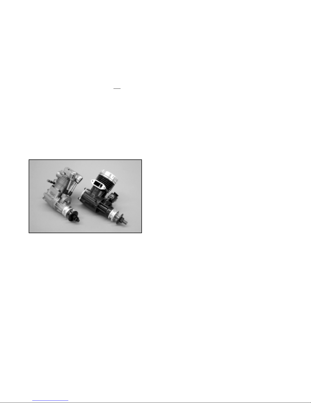
The SIG CAP 231EX ARF has been flown with a variety of 2 and
4-stroke engines. As everyone knows, there is no substitute for
power and the engines recommended for this model all provide
good power margins. Naturally, the larger engines in this range
make more power and will fly the CAP with more authority than the
smaller engines. It is simply a matter of how y
ou
want to fly this
airplane. We can tell you that our testing with both the Irvine 1.20
and 1.50 2-stroke engines was very good. Both engines make
great power and are easy to install and operate. In the case of the
1.50, we use a 16 x 8 APC prop and find the power sufficient to
achieve e xcellent v ertical performance, with power to spare . When
using a 2-stroke engine, mufflers are always a problem. But not in
this case! SIG stocks a special in-cowl muffler for use with the
CAP and either the Irvine 1.20 or 1.50 engines. This muffler is very
effective, fits perfectly and was expressly designed for use in the
CAP. It is SIG par t number IRV120150M. In the 4-stroke range,
good engine choices might be the YS 1.20 or 1.40 and
others such as the Saito 1.20, 1.50, or the newer 1.80.
We have done no testing of gasoline engines for this model and
cannot recommend any one particular engine over another.
However, should you decide to power your CAP with a gasoline
engine, be very sure to use gasoline compatible fuel tubing and a
fuel tank meant for gasoline.
TOOLS AND SUPPLIES
The CAP ARF requires a variety of typical hobby tools and
supplies found in most workshops. For example, you will need a
power drill, a selection of drill bits, a Dremel® Tool, screwdrivers
(both slotted and phillips), a soldering iron and solder, pliers, a
hobby knife with a selection of blades, a ruler, a tape measure,
masking tape, wax paper, petroleum jelly, threadlocking
compound, such as Loctite®, etc.
You will also need a variety adhesives. We suggest you have both
thin and thick SIG CA glues handy, as well as both 5 and
30-minute epoxy glues. For ease of mounting the elevator splitter
cables, we found that clear silicon adhesive works great. These
assembly instructions will be specific regarding adhesives. While
we all have our own preferences, we would urge you to give
careful consideration to these suggestions.
KIT CONTENTS
The following is a complete list of every par t included with your
CAP 231EX ARF kit. This kit was packed and inspected at the SIG
factory. Each part has been individually inspected and packed by
SIG employees. We urge you to be as careful as we have been,
using the check-off blocks to inventory your kit before beginning
assembly.
❑ 1 Fuselage, covered
❑ 1 Wing Set, covered
❑ 1 Aileron Set, covered
❑ 1 Aileron Ser vo Hatch Cover Set, covered
❑ 1 Wing Bolt Plate, covered
❑ 1 Vertical Fin, covered
❑ 1 Rudder, covered
❑ 1 Horizontal Stabilizer, covered
❑ 1 Elevator Set, covered
❑ 1 Fiberglass Cowl, painted
❑ 1 Molded Plastic Canopy Base, painted
❑ 1 Molded Plastic Tail Fairing, painted
❑ 1 Fiberglass Wheel Pant set, painted
❑ 1 Canopy, clear plastic
❑ 1 Tailwheel Assembly, complete
❑ 1 2-3/4" dia. Spinner Assembly, complete
❑ 1 500cc Fuel Tank Set
❑ 1 .021x72" Rudder Pull-Pull cable
❑ 4 3/32"O.D.x1/2" Alum.Pull-Pull Crimps
❑ 2 4-40 Threaded Rigging Couplers
❑ 1 1/8"dia.x2" Heat Shrink Tubing
❑ 1 Pre-Cut Wood Parts Package:
4 Aileron Servo Mounts - 13/16" sq. x 3/8"
2 Rudder Servo Mounts - 3/8"x 9/16"x1"
1 Throttle Tube Mount - D/C 1/8" plywood
1 Wing Joiner - laminated plywood
1 Front Wing Dowels - 5/16" dia.x1-9/16"
10 Mounting Pads - 1/8"x3/4"sq.plywood
❑ 1 2-56 Solder Clevis - Throttle
❑ 14 4-40 Blind Mounting Nuts
❑ 2 4-40 J-Bolts - Tank Mounting
❑ 4 4-40 Solder Clevises - Aileron/Elevators
❑ 7 4-40 Threaded R/C Links
❑ 2 4-40 x 2/34" Threaded Pushrods - Ailerons
❑ 2 4-40 x 2-1/8" Threaded Pushrods - Elevators
❑ 4 4-40 x 3/8" Slotted Bolts - Wheel Pants
❑ 6 4-40 Hex Nuts - Jam Nuts For Clevises
❑ 10 4-40 x1/2" Nylon Bolts - Canopy/Cowl Mounts
❑ 4 10-32 x 1" Socket Head Bolts - Motor Mounts
❑ 4 10-32 Blind Mounting Nuts - Motor Mounts
❑ 2 M5.5x35mm Nylon Wing Bolts
❑ 3 M4x25mm Landing Gear Bolts
❑ 12 #4x3/8" Sheet Metal Screws - Control Horns
❑ 1 Main Landing Gear, .190 hardened aluminum
❑ 2 3-3/16" dia. Main Wheels
❑ 1 1-1/4" dia. Tailwheel
❑ 2 Wheel Axles, hardened steel
❑ 2 Lock Nuts for wheel axles
❑ 4 Wheel Collars & Set Screws for wheel axles
❑ 8 #2 Wood Screws for aileron servo hatches
❑ 1 Motor Mount Set, glass-filled nylon
❑ 1 Pushrod Connector Assembly - Throttle
❑ 17 Nylon Double X Hinges
❑ 17 Steel Hinge Pins
❑ 3 Nylon Control Horns/RIGHT-Ail., Elev.& Rud.
❑ 3 Nylon Control Horns/LEFT - Ail., Elev.& Rud.
❑ 1 1/8"O.D.x18" Nylon Throttle P/R Tubing
2
Page 3
❑ 1 18" Steel Cable Throttle Pushrod
❑ 1 #64 Rubber Band - Fuel Tank Retainer
❑ 1 Set, Special CAP 231EX Decal Sheets:
2 #DKM277A
1 #DKM277B
❑ 2 3/4"x18" Yellow Covering Material Strips
❑ 1 Assembly Manual
COVERING MATERIAL
Your SIG CAP 231EX ARF kit has been expertly covered with #819
Dark Yellow Carl Goldberg Models ULTRACOTE®. Before
leaving the factory, all covered parts were inspected and cleaned
before being packed. Upon opening your kit you may find that the
covering has relaxed in some areas, requiring reshrinking. This is
perfectly normal and has nothing to do with the covering material
or how it was applied. It has to do with the wood beneath the
covering. Wood takes on or loses ambient humidity. Your CAP
ARF was manufactured in a relatively humid region of the world.
The wood was therefore holding humidity at the time the parts
were covered and bagged. Once the parts are removed from their
bags and subjected to drier conditions, the wood quickly loses
moisture and the covering may appear loose. This also explains
why most iron-on coverings sta y tight in the summer only to loosen
a little in drier winter conditions.
We suggest you use a heat gun and/or a cloth-covered iron to
completely go over the various covered parts of your CAP, making
sure the covering is drum tight and that every seam is well
adhered. Be sure to follow Goldberg's suggested heat settings for
ULTRACOTE® to avoid damaging the covering.
INSTALLING HINGES
As mentioned, the CAP 231EX is a large airplane with large,
powerful flying surfaces. This means that the hinges used to attach
these flying surfaces must be up to the task. For this
reason, we have included SIG's famous Double X Pinned Nylon
Hinges for use with this model. Properly installed, these hinges
are extremely smooth in action and very strong. The effort involv ed
in mounting these hinges will be more than compensated by the
close fit, smooth action and the peace of mind you have when
flying this airplane.
The hinging procedure is the same for all flying surfaces - ailerons ,
elevators and rudder. This manual will tell you when to hinge
the various surfaces - DO NOT hinge surfaces ahead of time,
unless instructed to do so. Note that each flying surface and its
corresponding installation point have been pre-slotted at the
factory for your convenience. Ailerons require four (4) hinges
each, elevator halves require three (3) hinges each, and the
rudder uses three (3) hinges, for a total of 17 hinges and hinge
pins. These are provided in a separate bag in your kit.
Begin by using a hobby knif e to completely open up and clear each
pre-slotted hinge openings. These slots need to be 1" wide to
accept the width of the hinges and about 5/8" deep on each side.
Next use a short length of thin saw blade material (such as a piece
of Dremel® saw blade) to open the width of the slots even further
to accept the thickness of the nylon hinges.
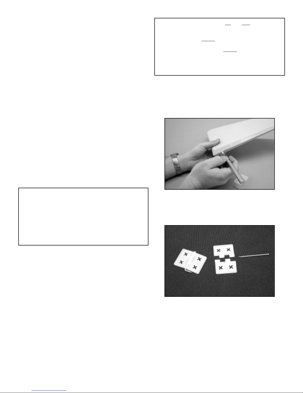
Assemble the hinges by inserting a hinge pin through the center
holes of both interlocking halves. Once the hinges are pinned, use
a pair of needle nose pliers to bend the sharp end of the pin
90°, as close to the hinge joint as possible, without binding it.
Pre-assemble all hinges in this manner.
Next, use a sharp #11 blade in your hobby knife to countersink the
round "knuckles" of one of the hinges into the beveled edge of the
flight surface (ailerons, elevators and rudder). Simply insert a
hinge into the flight surface until it bottoms out on the edge of the
bevel. Use your hobby knife to then cut a slot on each side of the
hinge knuckle to a depth equal to the knuckle (about 1/8").
Remove the hinge half and use your knife to cut the rest of the
balsa and covering away from the hinge slot, allowing the hinge
knuckle to recess into the flying surface. Repeat this process for
each hinge slot location on each flying surface.
3
MODELER S TIP: One of the most common problems
associated with shrinking any covering film is controlling the
heat around seams. Heat applied close to or directly onto
seams re-heats the covering adhesive and the seam will often
"crawl". This is easy to control. Just tear a few paper towels
into strips and soak them in cool tap water. Lay the wet strips
over any covering seam and use your heat gun or iron as you
normally would. The wet strips keep the seam cool while the
covering immediately next to it shrinks. This tip works great
with any iron-on covering.
IMPORTANT NOTE: There are left and right ailerons. You
can easily tell which aileron belongs with the proper wing
by the fit and noting the plywood hardpoint plate for the
aileron horns on the bottom
of each aileron. The outline of
this plate is easy to spot through the covering. It lines up with
the aileron servo hatch on the bottom of each wing panel.
The elevator halves are symmetrical and each has a
plywood hardpoint plate on both sides, allowing them to be
mounted on either the right or left side of the horizontal
stabilizer.
Page 4
The flight surface can now be hinged in place. Begin by using a
scrap wood stick to apply a coat of petroleum jelly, such as
Vaseline®, to both sides of the hinge knuckle, as well as each end
of the knuckle. Do not get this material on the hinge ends to be
glued! Petroleum jelly keeps epoxy from sticking to the hinge
joints. Hinges should be installed, star ting with the flying surface
side first. We also suggest using slow cure 30-minute type epoxy
for hinging because of the longer working time and strength. Apply
epoxy glue to one side of the hinge, liberally coating each side and
filling the "double X" cutouts. Insert the hinge into its slot, along
with the sharp end of the pin. Slide the hinge in place into
the previously cut recess. The free, unglued side of the hinge half
should be even with the front, beveled edge of the flying surface
when flexed 90°. Use a clean cloth and alcohol to carefully
remove any excess glue and move to the next hinge. Once the
hinges are in place in the flying surface, apply epoxy to each side
of the remaining hinge halves and insert them into the
corresponding slots in the wing, stab or fin. You want the beveled
leading edge of the flying surface to be as close to the mating part
as possible while still having full
left and right or up and down
movement ability. Again use alcohol and a cloth to carefully
remove all excess glue. Flex the flying surface to be sure it moves
freely. Tape the part in place and move to the next surface to be
hinged.
WING ASSEMBLY
The wing panels have been carefully built, sanded and covered at
the factory. The dihedral angle has been already built into the root
ribs of these two panels and should require no further adjustment.
However, before assembly, install the plywood laminate wing
joiner into one of the panels and slip the opposite panel in place.
Check the fit for alignment and that both root ribs come into firm,
straight contact with each other. If the wing joiner requires a little
trimming to achieve this fit, do so now. These instructions assume
a good fit.
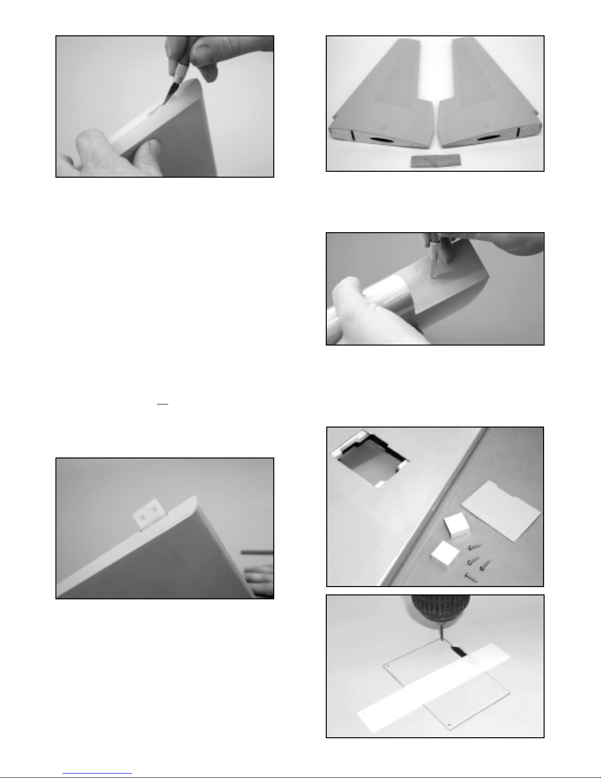
❑ 1) Prepare the two wing panels for assembly by first using
your hobby knife to remove the covering from the forward
wing dowel mounting holes, the top round holes for the
servo cable exits and the rear wing bolt mounting holes.
❑ 2) From the kit contents, locate the two (2) pre-covered aileron
hatch covers and eight (8) #2 x 3/8" screws. Trial fit the
hatch covers into the aileron servo openings to determine
which cover goes in the right wing and which goes in the left
wing. Position and tape the hatch covers in place, aligning
their servo arm cutouts with the ones in the wing opening.
4
Page 5
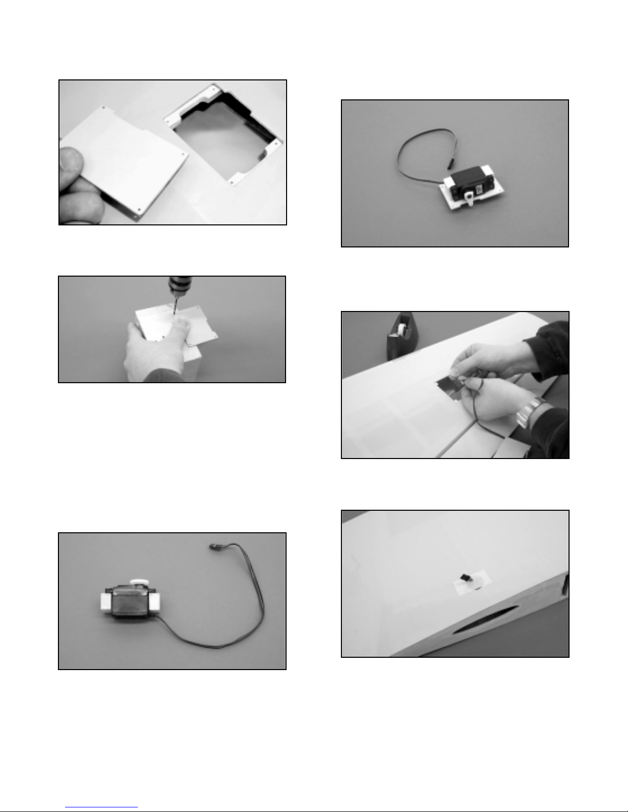
Drill a 1/16" dia. hole near each corner of the hatch covers.
Drill completely thru the hatch cover and into the hardwood
mounting beams that are in the wing.
❑ 3) Remove the hatch covers. Redrill the holes in each corner
of the covers with a 1/8" dia. drill bit to allow clearance for
the screws.
❑ 4) The aileron servos are mounted to the back, uncovered
sides of the servo hatch covers. From the kit contents,
locate the four (4) 13/16" sq. x 3/8" aileron servo mounts.
You will also need the servo mounting grommets, screws,
etc., supplied by the radio manufacturer for this step.
Remove the servo output arm/wheel and lay the servo flat
on its side. Position two of the mounting blocks beneath the
servo’s mounting arms, also flat on the same surface as the
servo. Use a bit to drill the servo mounting holes into the
wood mounting blocks. Use the screws that came with your
radio system to now mount the servos to the two mounting
blocks.
❑ 5) Attach the output arm back onto the aileron servo. Place
the servo/mounting block assembly onto the back side of
the servo hatch, aligning the output arm with the half slot
opening. The servo output arm must be able to move freely
back and forth without touching the slot’s edge - about 1/32"
clearance is adequate. With the servo now in this position,
use a sharp pencil to mark the hatch with the locations of
the servo mounting blocks. Remove the servo from the
hatch and apply thick CA or 5-minute epoxy the to bottoms
of the servo blocks and glue them in place to the hatch,
again checking for output arm clearance. Place a weight
onto this assembly and allow it to dry. Repeat this step with
the opposite servo hatch cover.
❑ 6) Before installing the aileron servos and hatch covers into
the wing panels, use your radio system to 1) center both
servos and 2) to check travel. Install the correct servo
output arms onto each servo, being sure they are upright at
90¡ to the servo and that they are long enough to clear the
wing’s surface during extremes of travel. Once this has
been checked, attach the 12" servo cable extensions to
both aileron servos. We would suggest that you also use
tape to secure these connections. Feed the servo
extension cable into the wing servo hatch opening, through
the holes in the ribs and finally out through the round holes
provided at the center of each wing panel. Tape the
connector to the wing’s top surface. Install the aileron
servo/servo hatch in place into the wing and use the
#2 x 3/8" washer head screws to secure the hatch. Did you
remember to install the output arm screws in each servo?
5
Page 6
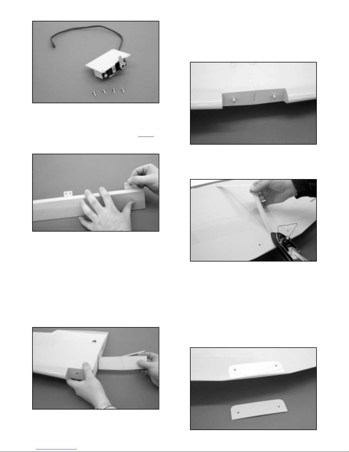
❑ 7) Using the hinging instructions provided, install and glue the
four required hinges into each aileron. Hinge each aileron
to it's appropriate wing panel - remember that the inset ply
aileron horn mounting pad is located on the bottom
side of
each aileron. Carefully clean any excess epoxy with a
clean cloth and alcohol.
❑ 8) Use 30-minute epoxy to liberally coat the inside of each
wing joiner pocket in both wing panel roots. Liberally apply
epoxy glue to the exposed wood center ribs of each wing
panel and apply glue to the laminated plywood wing joiner
itself. Insert the wing joiner into one wing panel pocket and
slide the other panel in place over the exposed joiner end,
joining the two panels at the center. Press the panels
together and use alcohol and a cloth to remove all excess
glue. Firmly tape the front and trailing edge joints to align
and secure them. Place a clean rag on the floor next to a
wall. Stand the wing upr ight, with one wingtip on the cloth,
as vertical as possible, leaning against the wall. Place a
weight on the upper wing tip and allow this assembly to fully
cure.
❑ 9) Use slow cure 30-minute epoxy to install the two front
locating dowels into the front wing plate, leave 1/2" of dowel
exposed to engage the corresponding fuselage mounting
holes. Use plenty of glue and a stick to get it into the two
holes before inserting the dowels. Visually be sure these
dowels are straight in the wings and not at angles. With the
dowels in place, stand the wing up on its leading edge and
allow the glue to cure.
❑10) Use the 3/4" x 18" lengths of ULTRACOTE® supplied with
your kit and a heat iron to carefully cover the center wing
glue joint. Cover the bottom seam first, followed by the top
seam.
❑11) The wing is now fitted to the fuselage. First engage the two
forward dowel ends in the wing into the two dowel holes in
the forward, bottom fuselage former. Because of slight
differences in the manufacturing process, it may be
necessary to adjust one of these holes slightly to receive
the wing dowels. If this is the case, only adjust one of the
holes. This is easiest to do with a #11 blade in your hobby
knife, opening the hole to either the right or left, allowing the
wing dowel to pass. Once the wing engages into the front
of the fuselage, press it in place into the wing saddle.
❑12) From the kit contents, locate the covered plywood wing bolt
plate. The bolt plate has two holes that will line up with the
6
Page 7
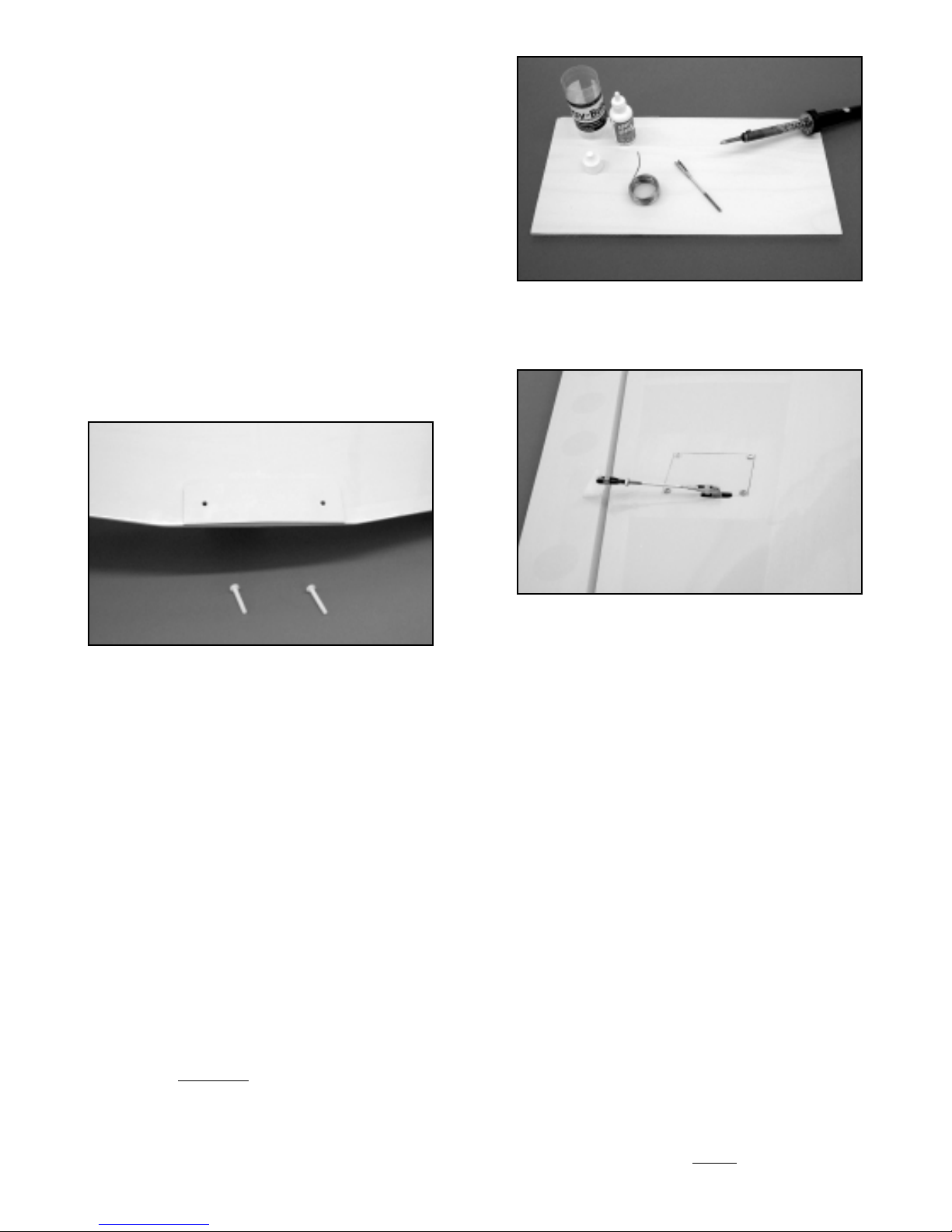
wing bolt holes already drilled in the rear center section of
each wing panel. Use your hobby knife to remove the
covering over the two wing bolt holes in the wing panels
and the bolt plate. Place the plate in position over the
trailing edge of the wing, aligning its rear edge with the
fuselage bottom and its two bolt holes with the bolt holes in
the wing panels. In this position, press the bolt plate to the
wing and use a pencil to draw the outline of the bolt plate
onto the wing. Remove the wing from the fuselage. Use a
hobby knife to remove the covering material on the wing,
about 1/8" inside the bolt plate outline. Glue the bolt plate
to the wing - aligning its bolt holes with those in the wing with thick CA glue. Hold or clamp the plate fir mly to the
wing, allowing the glue to set.
❑13) From the kit contents, locate the two M5.5 x 35mm nylon
wing bolts. Mount the wing in place to the fuselage and
insert the two nylon wing bolts into the two holes. Thread
the bolts into the blind mounting nuts and use a
screwdriver to tighten them and the wing in place onto the
fuselage. Do not over tighten the bolts. Remove the bolts
and the wing from the fuselage.
❑14) Connect aileron servo Y-harness to your receiver and servo
leads to the Y-harness. Turn on your transmitter and plug
your airborne batteries into your receiver. You should now
be able to operate your aileron servos.
• Center servos with trims and/or through the radio's
computer.
• Carefully center servo output arms to exactly 90° upright
when at neutral.
• Test the action of the servos, making sure the output
arms move freely and that they move in the correct
directions for left and right aileron action.
• Turn off the radio system, disconnect the servos from the
Y-harness.
❑15) From the kit hardware provided, locate one left and one
right nylon control horn and four #4 x 3/8" sheet metal
screws. Tape the ailerons in neutral and lay the wing
upside down on your bench. Position one of the ailerons
horns in place on the bottom, leading edge of the aileron,
lined up with the servo output arm. Mark the horns hole
locations onto the aileron with a pointed marker pen. Drill
two 3/32" dia. guide holes into the aileron at the mar ks just
made. Mount the horn in place, using two #4 x 3/8 sheet
metal screws. Repeat this process on the opposite aileron.
❑16) Make the aileron pushrods by first soldering a 4-40 solder
clevis to the unthreaded
ends of the two 4-40 x 2-3/4" steel
pushrods. Thread a 4-40 hex nut onto the threaded end of
the pushrod, followed by a threaded clevis. Connect the
solder clevis end of the pushrod to the aileron servo output
arm. Holding the pushrod in place to the aileron horn,
adjust threaded clevis as needed to match its connecting
pin to the middle hole in the horn - snap the threaded clevis
in place to the horn. Repeat this process on the opposite
wing panel. Remove the tape holding the ailerons in
neutral to the wing panels.
❑17) Check the aileron servo action with your transmitter by
connecting the servos to your receiver. Final adjustments
of all flying surfaces will be done after assembly is
complete. This completes the wing assembly.
ENGINE MOUNTING
It is assumed that most modelers will side mount their engines,
with the head in the right cowl cheek. The CAP has a relatively
large amount of area for this type of engine mounting and it is
highly recommended. Realistically, the engine could be mounted
in any position, including upright or inverted, as long as it is
understood that the cowl must be cut to clear it. These instructions
assume that your engine will be mounted on its side with the head
in the right cowl cheek. Accurate horizontal and vertical engine
centerline marks are on the firewall. These marks must be used in
order to position your engine accurately to the intended
thrustline and to accurately mount the cowling. The round hole in
the firewall accepts the front of the fuel tank and is purposely
offset to allow fuel line clearance when installing most engine
types. The supplied motor mounts are generic. They will accept
many engines but not all. Check your engine for fit to these mounts
before using them. Other after-market mounts are available and
will work on this airplane if you choose.
❑ 1) Use a straightedge and pencil to highlight the horizontal and
vertical centerline marks on the firewall.
❑ 2) Measure the width of your engine's case, at the mounting
lugs. (example: an Irvine 1.50 2-stroke has a case width of
2.03" (2-1/32") between the mounting lugs and a Saito 1.50
measures almost exactly 1.80" between the mounting
lugs.). Divide the case width measurement by 2 and place
a mark on each side of the v
ertical centerline on the firewall.
7
Page 8
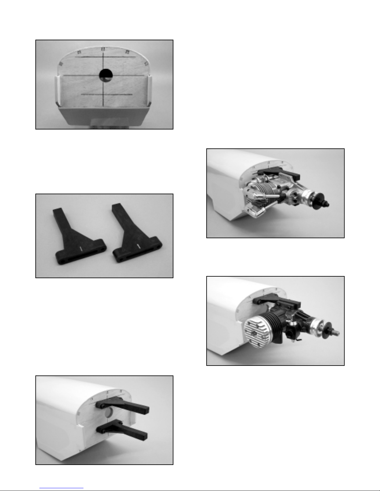
These marks become the inside locator marks for the two
motor mounts.
❑ 3) The motor mounts have a centerline "tick" mark at their
mounting ends. Line this mark up with the vertical
centerline, with the inside edge aligned with the case width
marks just made. This is the position the mount needs to
be, in order to fit your engine. Mark the mount's bolt hole
locations onto the firewall with a pencil or a little shot of
paint from a spray can - remove the mount. Repeat this
procedure for the opposite mount arm.
❑ 4) Use a 3/16" dia. bit to drill the four required holes in the
firewall for the two motor mount arms, being careful to
center them as exactly as possible. Once all four holes are
drilled, change drill bits to a 1/4" dia. and redrill the four
holes to allow clearance for the 10-32 blind nuts.
❑ 5) Apply epoxy glue to the four 10-32 blind nuts, keeping glue
away from the threads. Install the nuts from the inside of
the fuselage, pressing them firmly in place. Use a motor
mount arm and a 10-32 x 1" socket head bolt to pull the
blind nuts firmly into place in the back of the firewall.
Remove the bolt after each nut is secured. When all four
nuts are in place, use a cloth and a little alcohol to remove
excess glue from the inside back face of the firewall.
❑ 6) Bolt the two motor mounts to the firewall. Place your engine
on the mounts. Move the engine on the mounts until it
measures exactly 6" from the front face of the prop drive
flange, back to the firewall. This is the distance your engine
needs to be from the firewall for cowl mounting and prop
clearance purposes. Mar k your engine's mounting lug bolt
hole locations onto the motor mount arms and remove the
engine.
❑ 7) Note that we have supplied you with most of the hardware
needed to assemble this kit, with the exception of engine
mounting bolts. These you will need to obtain yourself. We
have used and strongly recommend, steel he x head bolts at
least 1-1/4" - 1-1/2" long, with washers and lock nuts. For
example, 8-32 bolts will fit and work with both the Saito and
Irvine 1.50 engines -
DO NOT USE SELF-TAPPING OR WOOD SCREWS
FOR MOUNTING YOUR ENGINE ON THE SUPPLIED
MOTOR MOUNTS!
Drill the four required mounting holes in the motor mount
arms, being very careful to drill them perpendicular to the
mount arm at 90° angles, using the hole locations just
made. These must be clearance holes, which allow the
bolts to slip through. In the case of 8-32 bolts, an 11/64"
dia. drill bit will provide clearance holes. With the engine's
muffler and needle valve removed, mount the engine in
place to the motor mount arms.
❑ 8) You will of course need to mount a muffler to your engine
and in turn, the muffler must be considered when mounting
the cowl in the next assembly step. If you are using either
the Irvine 1.20 or 1.50 2-stroke engines to power your CAP,
SIG has a muffler available for these engines that is not only
light in weight but fits perfectly within the cowl. This muffler
is SIG part number IRV120150M and is available
separately.
8
Page 9
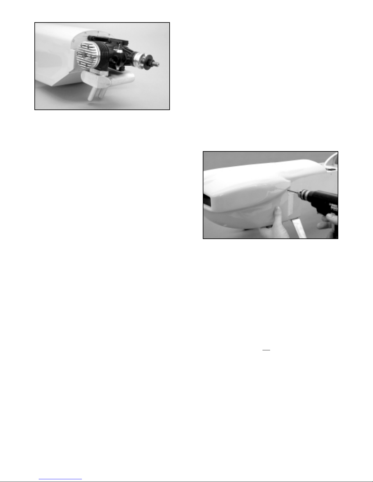
MOUNTING THE COWL
Before mounting the cowl, carefully inspect its inside rear edges.
Use sandpaper to smooth the inside rear surface of the cowl,
making it free of any bumps or ragged edges that may scratch or
dent the fuselage when pressed in place. Also, mak e sure the four
mounting holes are open and free of any debris.
❑ 1) Carefully fit the fiberglass cowl in place over the engine and
back onto the fuselage. The head of your engine will likely
fit inside the cowl. If it does not, you will now need to open
the cowl cheek, allowing clearance of the head, rocker arm
cover or whatever else may be contacting the inside of the
cowl. This is largely a matter of carefully observing where
the engine part is contacting the cowl and then marking that
location on the cowl with a felt marker. Remove the cowl,
and use a Dremel® Tool to make a small hole in the cowl
at the point of contact. Refit the cowl, checking the hole
location and size, adjust as needed and again use the
Dremel® Tool to work on the opening. This method is
referred to as "sneaking up" on the opening, making a
perfect clearance hole. A handy tool for this job is a small
penlight. The penlight can be used from the inside or
outside of the cowl to highlight and spot required hole
locations. We suggest using a clearance distance rule of
thumb of at least 3/16" from the cowl to any engine part.
❑ 2) Once the cowl is in place without any part of the engine
contacting it, push the cowl back onto the fuselage until the
engine prop mounting flange emerges from the front
spinner ring. This flange must clear the front of the cowl by
at least 1/16".
❑ 3) Slip the spinner backplate in place over the engine prop
shaft, pushing it all the way back to the prop mounting
flange. Mount a prop or prop stub "dummy" in place on the
drive shaft, followed by the thrust washer and retaining nut.
Tighten this assembly sufficiently to bring the spinner
backplate firmly in place against the prop mounting flange.
❑ 4) We suggest mounting the cowl with a 1/16" space between
the back of the spinner and the cowl. This allows for small
thrust adjustments, if desired. Use scrap pieces of 1/16"
plywood to space the cowl behind the back surface of the
spinner backplate. Center the spinner backplate to the cowl
and use masking tape to hold it securely in this position.
Use masking tape to secure the back of the cowl to the
fuselage, leaving the four pre-drilled mounting holes
uncovered. With the cowl securely in place, it is in position
for mounting to the fuselage.
❑ 5) Use a 7/64" dia. drill bit to drill holes through the fuselage,
centered in each of the four holes in the cowl (1 hole on
each upper right and left sides of the cowl and 1 hole on
each bottom right and left sides of the cowl). From your
parts bag, locate two (2) 1/8" x 3/4" sq. plywood plates, four
(4) 4-40 x 1/2" nylon bolts and four (4) 4-40 blind mounting
nuts. The two 1/8" x 3/4" sq. ply plates will be glued to the
inside of the fuselage at the upper right and left hole
locations, directly over the holes just drilled. Hold one of the
ply plates in place, flat against one of the upper inside cowl
mounting holes and use a sharp pencil, from the outside, to
make a mark on the plate. Remove the plate and use a
5/32" dia. bit to drill a hole through the plate at the mark just
made. Apply epoxy glue to one of the 4-40 blind nuts and
insert it into the plate, pressing it firmly in place - wipe off
any excess glue. Apply glue to the face of the ply plate and
hold it in place inside the fuselage. Before pressing the
plate in place, run one of the 4-40 nylon bolts through the
cowl and into the fuselage. Engage the bolt into the threads
of the blind nut, mounted in the ply plate. Thread the bolt in
place, tightening it until the plate is firmly in place against
the inside of the fuselage. Repeat this procedure to secure
the opposite side of the cowl with a nylon bolt, plate and
blind nut.
❑ 6) The two bottom cowl holes are handled in a similar manner
but without using plywood plates. Apply epoxy glue to one
of the 4-40 blind nuts and insert it into one of the bottom
inside cowl hole locations. With the fuselage flat against
your workbench, use pressure to seat the nut firmly into the
plywood. Wipe off any excess glue and repeat the process
with the remaining blind nut and cowl mounting hole.
❑ 7) Use the four nylon 4-40 x 1/2" bolts supplied in your kit to
secure the cowl to the fuselage from the outside. Remove
all masking tape, the 1/16" plywood spinner/cowl spacer,
the retaining nut, prop and spinner backplate. Check your
work and remove the cowl from the fuselage.
❑ 8) An opening must now be made in the bottom of the cowl.
This opening is absolutely necessary to allow incoming air
to properly flow through and exit the cowl. Without this
opening, your engine will
overheat and quit. If you are
using a 2-stroke engine, such as the Irvine 1.20 or 1.50 or
a 4-stroke, such as the Saito 1.20, 1.50 or the 1.80, we
suggest using an opening, which measures 4-1/8" wide by
7" deep. This size opening allows the exhaust pipes on
the recommended SIG muffler for the Irvine engines to
clear the cowl with plenty of additional air exit area, as well
as allowing plenty of air for 4-stroke engines. This opening
may certainly be "customized" for your particular
engine/muffler set-up, as long as there is sufficient air exit
area.
Stand the cowl upright on its rear edge, nose up, with the
bottom side facing you. You will need a ruler, a 90° triangle
and a fine point non-permanent felt marker pen to mark the
cowl for cutting. The approximate width of the bottom rear
edge of the cowl is 6-1/2". Make a mark at the center of the
9
Page 10
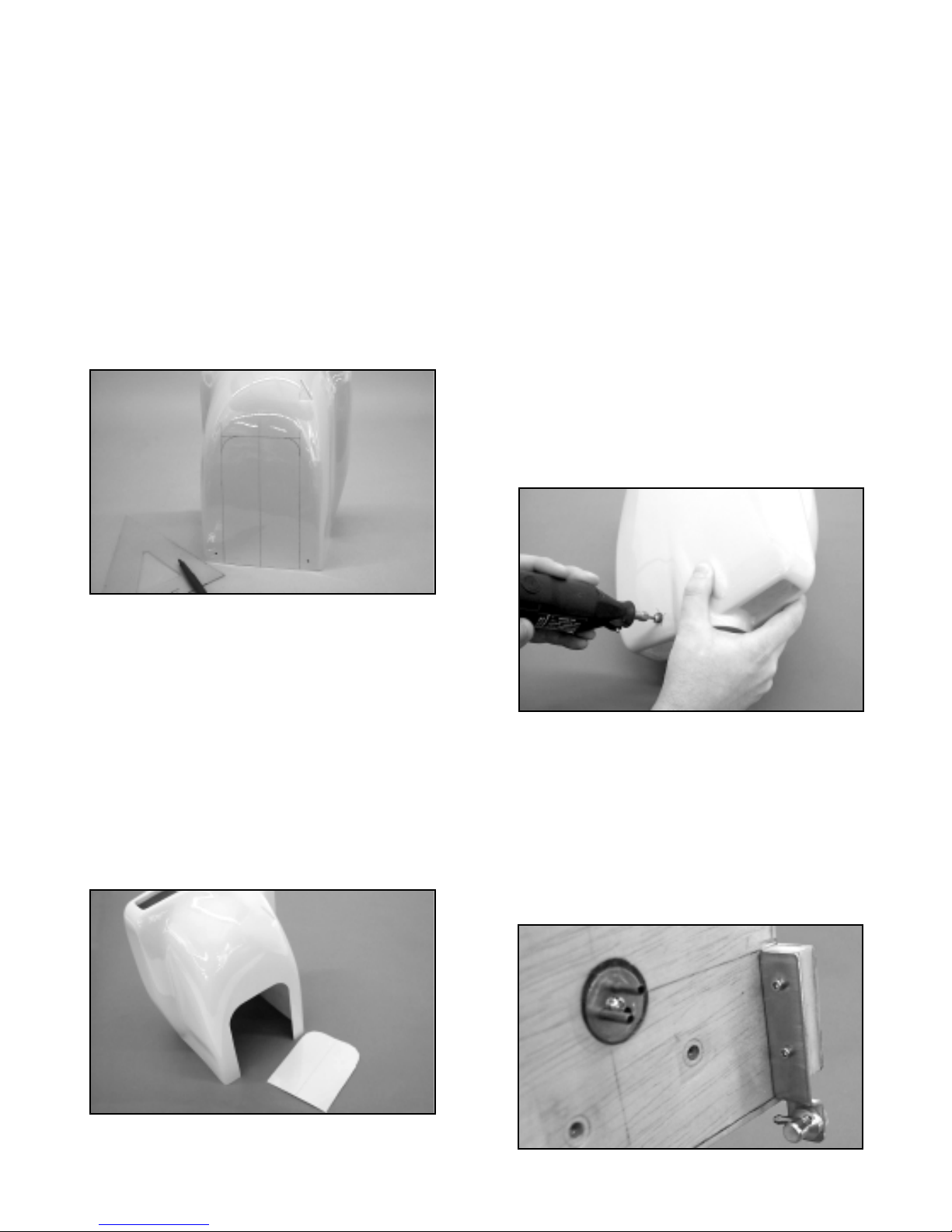
cowl, approximately 3-1/4" in from the outer edge. Stand
the triangle up against the bottom edge of the cowl, aligned
with the mark just made. Use the felt marker to draw a
vertical line up toward the nose about 8" long. Measuring
from this centerline, make a mark at 2-1/16" to the left of the
centerline and another at 2-1/16" to the right of the
centerline. Again using the triangle and the marks just
made, draw a straight ver tical lines on the cowl from the
bottom edge up towards the nose, again about 8" long.
These two outer lines should parallel the centerline.
Measure 7" up from the back edge of the cowl, making
a mark at one of the outer vertical lines. Repeat this
measurement and mark on the other outer vertical line. Use
a straightedge and marker pen to connect these two marks.
This gives you the area to be cut out from the bottom of the
cowl. To avoid sharp corners and for a better look, we
suggest using a circle guide to round the two upper corners
of this cut out area.
The fiberglass can be cut from the cowl easily, using a
Dremel® Tool and a large cut-off wheel. Before cutting out
the cowl opening be sure to wear safety glasses and a
mask of some kind to avoid inhaling any fiberglass dust.
Carefully cut the fiberglass, using the lines previously
drawn. If you are careful, you will find that you can get
fairly close to the lines with the cut-off wheel. The goal is to
remove most of the material within the lines. Once the
piece is cut and removed, exchange the cut-off wheel for a
sanding drum bit in your Dremel® Tool. Use the drum
sander bit to round the upper two corners and to lightly
clean up any jagged edges. Use 220 sandpaper to clean
up the edges of the cutout, without sanding the paint. Make
sure the edges are uniform and free of any loose glass.
Remove all fiberglass dust from the cowl with alcohol and a
clean cloth.
❑ 9) Mount the now trimmed cowl back onto the fuselage, over
your engine. In this step you will determine the location for
the hole required for your engine's needle valve to exit the
cowl. This is easiest done using the penlight mentioned
earlier in step #1 and fine line marker pen. First find the
approximate location of where the needle valve will exit by
looking carefully at your engine's carburetor. Mark that
location onto the cowl.
Now look a little closer and use the penlight to adjust the
mark just made from the outside of the cowl. Reposition the
mark as required to get as close as possible to the actual
exit location. Use the Dremel® Tool and a small tipped
grinding bit to make a small hole (maybe 1/16" in diameter)
in the cowl, at the exit mark just made. Chances are that
you were quite close to the actual exit point. Stick a piece
of music wire into the hole, down to the needle valve hole in
the carburetor. Carefully observe if the hole needs to be
repositioned to straighten up the wire, as if it were the
needle valve. Make another mark on the cowl and again
use the Dremel® Tool to open the hole just a little towards
the correct position. In this manner, continue checking and
adjusting the exit hole until it aligns perfectly with the
carburetor/needle valve position. Use the Dremel® Tool
and tapered bit to open the hole enough to insert and install
the needle valve in the carb. Be sure the hole has at least
3/32" clearance around the needle valve to avoid contact.
❑10) You must be able to fuel and de-fuel your CAP
conveniently. There are several commercially available
fueling systems that would work with this model. We have
used and highly recommend the Du-Bro #334 Kwik-Fill
Fueling Valve for glow engines. In this optional step, we will
explain how we mounted our fuel valve. All that's required
is to make a simple aluminum bracket, mount it to the
firewall area and make a small hole in the cowl to accept the
fuel probe. We mounted our filler bracket on the inside face
of the left hardwood protrusion on the left edge of the
firewall. In order to meet the cowl as closely as possible but
10
Page 11
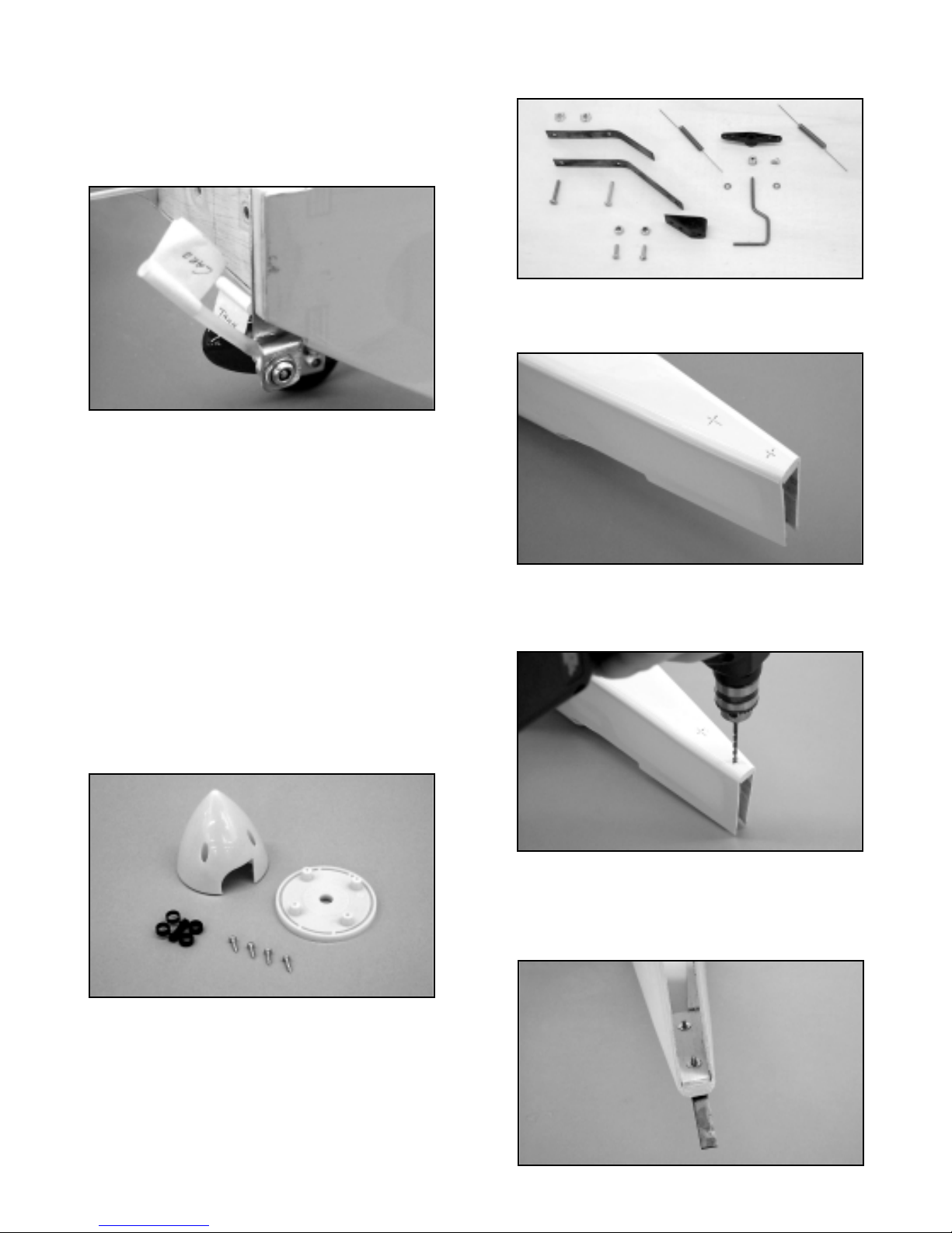
not contact it, we bent the bracket to match the
fuselage/cowl side when viewed from the front. Our
bracket was made from K&S 1/16“ aluminum sheet. Drill
the bottom end of the bracket with a 3/8" dia.hole to accept
the fuel valve body and drill two 7/64" dia. holes at the top
end, allowing it to be mounted in place with two #4 sheet
metal screws (not supplied).
A small hole in the cowl, directly over the fuel valve, must
now be made to allow the fuel probe to be inserted into the
valve. Place your penlight behind the bracket, at the hole
for the filler valve. You can now clearly see exactly where
the hole must be on the outside of the cowl. Mark this
location with a marker pen, remove the cowl and use the
Dremel® Tool and a tapered bit to open up a hole about
5/16" in diameter at the mark made earlier. Put the cowl
back on and check your work. Adjust the hole as needed to
allow easy insertion and removal of the fuel probe.
With the engine and cowl mounted in place, the spinner can
now be fitted to the engine. This spinner is a high quality
SIG unit that has been molded to accept APC propellers up
to 16 x 8 in size. The shaft hole in the base of the spinner
must be made to fit your particular engine. If required, shaft
spacers are included. If your engine shaft is larger than the
hole size in the spinner, it can be drilled to fit. This should
be done using a drill press. Slip the base plate onto the
shaft. Slip the propeller onto the shaft and secure it with
your engine's nut and washer. Snap the spinner nose cone
in place into the base plate channels and use the four
mounting screws supplied with the spinner to mount it to the
base plate. Don't over-tighten the screws but bring them up
snug.
GENERAL FUSELAGE AND TAIL GROUP ASSEMBLY
❑ 1) From the kit contents, locate the bag containing the
tailwheel assembly. Lay the fuselage upside down on your
bench. Note that the tailwheel assembly will be mounted
directly to the fuselage at the rearmost location. Hold one
of the two tailwheel leaf springs in place on the fuselage,
lined up with its centerline. Use a fine tip felt marker to mark
the locations of the two mounting holes in the spring, onto
the fuselage. Remove the spring and use a 5/32" dia. drill
bit to drill two holes through the fuselage bottom at the hole
locations just made.
❑ 2) Turn the fuselage over, exposing the inside rear of the
fuselage. Apply epoxy glue to the front surfaces of the two
4-40 blind nuts and insert them into the two holes just
drilled. Press them into the wood and wipe off any excess
glue, keeping glue out of the threads.
11
Page 12
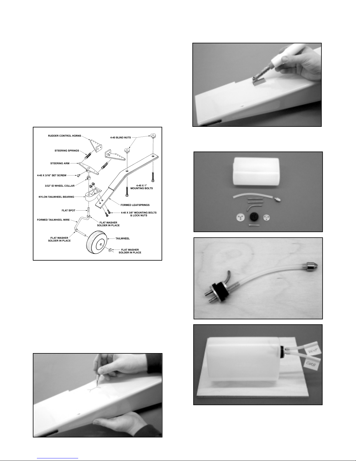
❑ 3) As shown, assemble the nylon bearing bracket to the
longer of the two leaf springs with two 4-40 x 3/8" bolts and
two 4-40 locknuts. Slip a #2 washer over the top of the
tailwheel wire, sliding it down to the top bend in the wire.
Solder the washer in place to the wire as shown. Slip
another #2 washer over the axle end of the tailwheel wire,
sliding it back to the first bend - solder the washer in place.
Insert the top end of the tailwheel wire into the plastic
bearing bracket, up to the soldered washer. Insert the
wheel collar into the bottom of the steering arm, aligning its
threaded hole with the arm's clearance hole. Install the
4-40 x 3/16" bolt through the steering arm hole, threading it
into the wheel collar. Slip the steering arm in place over the
exposed top end of the tailwheel wire, with the set screw
facing the rear. Leave clearance for free movement and
tighten the set screw in place to the wire.
❑ 4) Place the 1-1/4" dia. tailwheel onto the axle end of the wire.
If the wheel is a tight fit, use a 7/64" dia. drill bit to open the
axle hole a little. The remaining #2 washer will be soldered
in place to retain the tailwheel. To protect the plastic wheel
hub, use a scrap piece of 1/32" plywood over the axle and
against the wheel. Slide the washer in place against the
plywood and solder it in place - remove the plywood
spacer. The completed tailwheel assembly is now bolted in
place to the fuselage, using two 4-40 x 1" bolts. Use
non-permanent Loctite® on the bolt threads to prevent them
from loosening.
❑ 5) Use a sharp #11 blade to open up the two elevator servo
cutouts, beneath the stabilizer saddle at the top rear of the
fuselage. Use a trim seal iron to tack the loose covering
around into these cutouts. Trim and remove the excess
covering material.
❑ 6) Assemble the fuel tank as shown. Be sure to label the
"vent" and "carb" lines for later identification.
❑ 7) Trial fit the tank in place into the front of the fuselage to
familiarize yourself with how it mounts. The front fits into
the hole in the firewall and the end of the tank requires
support. For this you will need to now install two J-hooks,
12
Page 13
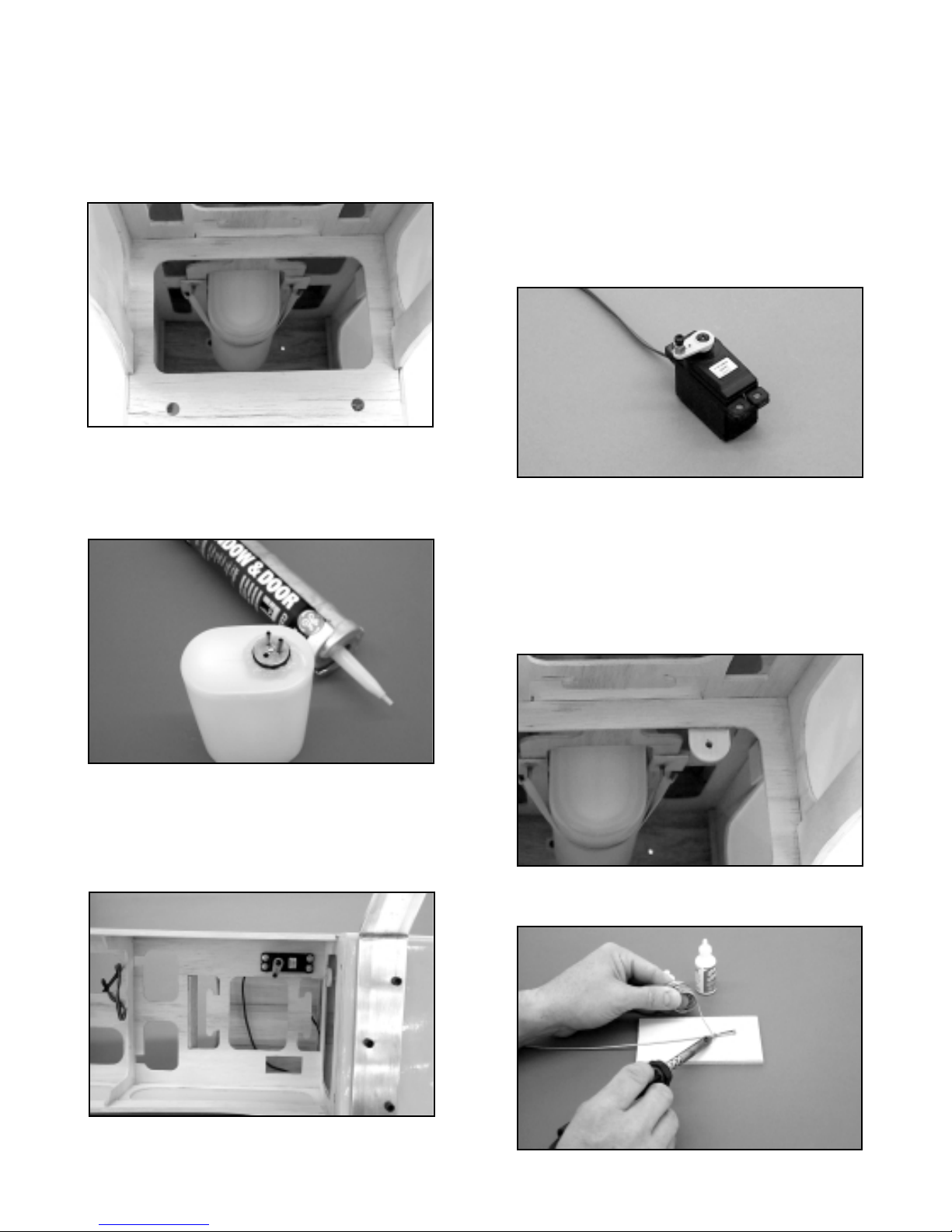
one on either side of the tank. With these in place, a #64
rubber band is hooked to one J-hook, pulled around the
tank and hooked to the opposite J-hook. With the tank in
place, use a pencil to mark the J-hook locations - remove
the tank. Glue two 1/8" x 3/4" plywood mounting pads over
the hook location marks. Use a twist dr ill with a 5/64" bit to
drill guide holes through the pads and fuselage supports.
Thread the hooks in place.
❑ 8) Apply a bead of silicon adhesive around the neck of the
tank, where it contacts the inside of the firewall. Fit the tank
in place into the fuselage, pressing it firmly against the
firewall. Suppor t the rear of the tank to the fuselage with a
#64 rubber band, using the J-hooks.
❑ 9) Two throttle servo locations are provided, one on each side
of the fuselage. Choose the side that corresponds with the
throttle arm on your engine. Attach the grommets supplied
with your radio system to the servo mounting lugs and use
the mounting screws, also supplied with your system, to
mount the throttle servo.
❑10) From your kit, locate the 1/8" OD x 18" nylon throttle tubing,
the 18" length of steel throttle cable, the die-cut 1/8"
plywood throttle tube support (small part with one rounded
end with a hole for the tube), the pushrod connector
assembly (3/16" hex brass body, nylon retainer and
4-40 x 1/8" socket head cap screw) and the 2-56 solder
clevis. Drill a 1/8" dia.hole through the firewall, aligned with
your engine's carburetor throttle arm. From the front, insert
the 1/8" nylon tube through the firewall and into the
fuselage, leaving 3" exposed in front of the firewall (typical
when using a 1.20 or 1.50 2-stroke engine). With the tube
in place, turn the fuselage over and note the location of the
tube in relationship to the throttle servo. You want to
position the tube directly in front of the servo's output arm.
Assemble the pushrod connector to the servo output arm.
Slip the die-cut 1/8" plywood throttle tube support part over
the end of the tube, back to the forward fuselage former
location. Glue the support in place to the inside front of the
former, locating the tube directly in front of the throttle servo
output arm. Use a razor blade to trim the tube to a length
of 1" behind the die-cut tube support. Remove the tube
and sand its surface with 220 sandpaper to rough it a little.
Reinstall the tube and glue it in place to the firewall and the
die-cut tube support with thick CA glue.
❑11) The steel throttle cable is now prepared for installation.
Solder the provided 2-56 solder link to one end of the cable
13
Page 14
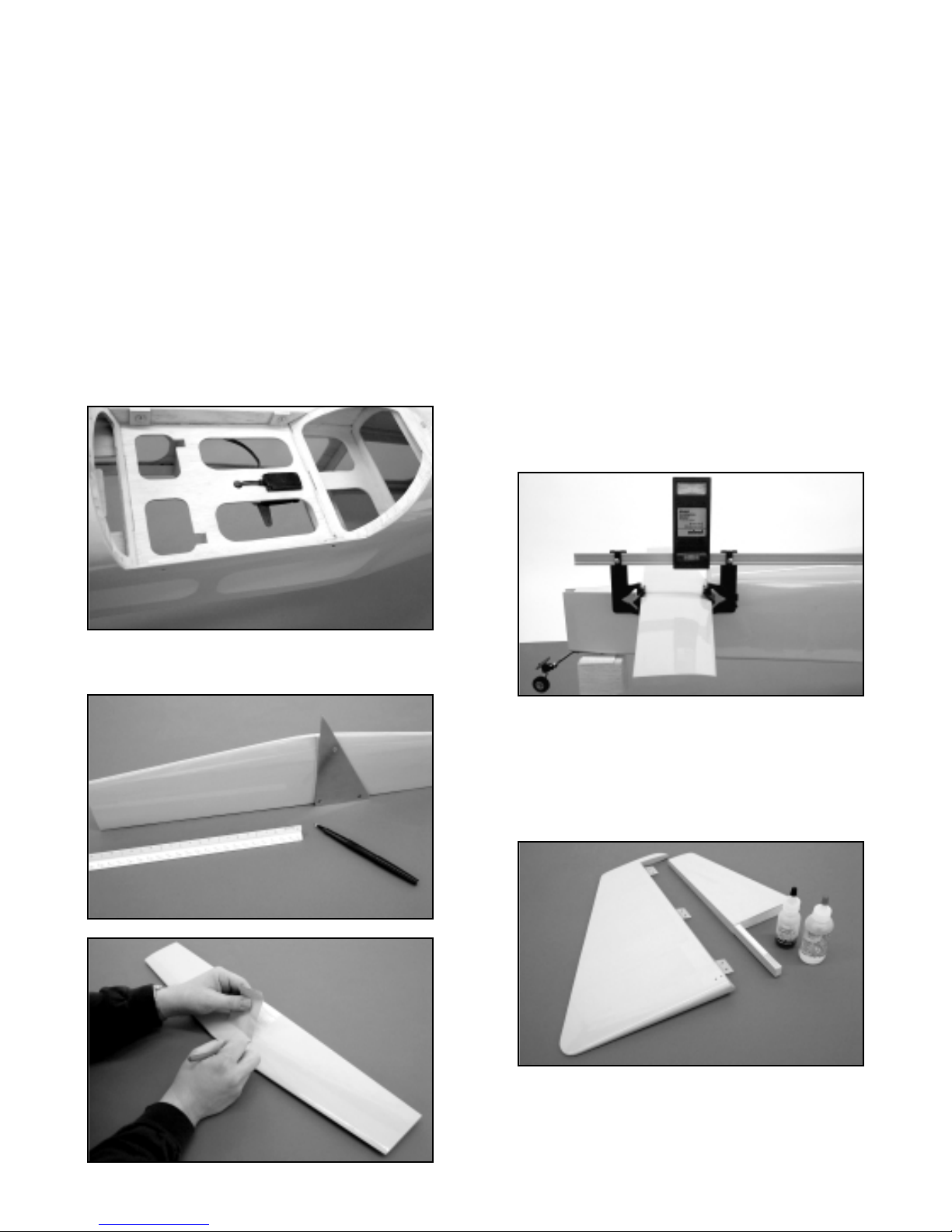
- this is the carburetor end. Install the brass pushrod
assembly to the output arm on the throttle servo and press
the output arm in place onto the servo. From the firewall,
insert the bare end of the cable through the throttle tube,
connecting the solder link to your engine's throttle arm.
The cable is now cut to length, leaving about 2" of extra
length behind the brass pushrod connector. The extra
length will be useful when setting up the throttle later on.
❑12) From your kit contents, locate the two 3/8" x 9/16" x 1"
hardwood rudder servo mounting blocks. As shown, the
rudder servo is mounted in the center servo cutout, directly
beneath the canopy base. In order to mount the ser vo, the
two hardwood blocks must be glued in place at the front and
rear edges of the cutout. Test-fit the servo first. If the
opening needs enlargement, do this now until a good fit is
achieved. Epoxy the mounting blocks in place. As shown,
we drilled a small diameter hole in front of the servo,
redirecting the connector back into the fuselage. Use the
grommets and screws provided with your radio system to
securely mount the rudder servo in place onto the blocks.
❑13) Use a ruler to find the exact center of the stabilizer, marking
the location with a felt pen. Use a triangle to draw a 90°
centerline directly onto the stab at this location. Place the
stabilizer into the fuselage, centering it visually. Holding the
stabilizer in place, use the felt pen to mark the stab bottom,
where it meets the fuselage on each side. Remove the
stabilizer and use a #11 blade to carefully remove the
covering material just inside of these two lines, including
where it contacts the fuselage at its leading and trailing
edges.
❑14) In this step you will prepare the horizontal stabilizer for
mounting by first checking it's alignment with the wing and
fuselage. Start by using the three M4 x 25mm bolts
provided to mount the landing gear to the fuselage. Bolt the
wing in place. Attach a Robar t Incidence Meter tool to the
inboard leading and trailing edge of the wing and prop the
rear of the fuselage up until it is level according to the
meter. In this position, the wing incidence should read 0°.
Place the stabilizer into its saddle in the fuselage and use
weights to secure it. With the stab in this position, remove
the Incidence Meter from the wing and attach it to the
leading and trailing edge of the stabilizer. Ideally the meter
will again read 0°. If it does not, then the saddle in the
fuselage must be adjusted to seat the stab at 0°. Use
sandpaper or a #11 blade to adjust the stab saddle as
needed. Remove the stab from the fuselage.
❑15) To prepare the fin for mounting to the fuselage, first,
pre-hinge the rudder, gluing the hinges into the rudder, but
not into the fin. Remove the covering material from the
sides of the fin tailpost that fits into the fuselage. Draw a
centerline onto the fuselage fin mounting base, to assist you
in aligning the fin. Using slow-cure epoxy, apply glue to the
bottom of the fin and to the tailpost sides, where it contacts
the fuselage. Slide the fin in place into the fuselage and
onto the fin mounting base. Align the leading edge of the
fin with the centerline and use tape to hold the fin in place.
With the fin in this position, view the airplane from the front
and rear to be sure that the fin is absolutely 90° upr ight to
14
Page 15
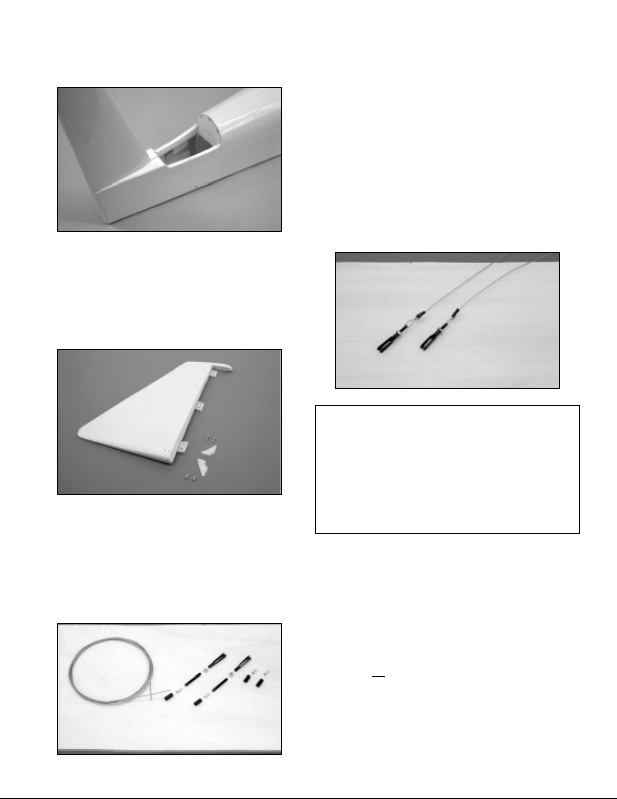
the fuselage and aligned with the centerline of the fuselage.
Wipe off any excess glue with alcohol. Adjust as needed
and tape securely. Remove the wing and allow the glue to
cure completely.
❑16) Install a right and left rudder horn to the bottom of the
rudder using #4 x 3/8" sheet metal screws. The rudder has
inset plywood mounting pads on each side for this purpose.
The two rudder horns directly oppose one another and
should be lined up with the pull-pull exits at the bottom rear
of the fuselage. The rudder is now hinged to the fin using
epoxy glue on the hinges - remember to protect the hinge
knuckles with petroleum jelly. Clean off any excess glue
and allow to cure.
❑17) The rudder pull-pull system is now installed. Begin by using
your radio system to accurately center the rudder servo.
Install the output arm onto the rudder servo. From your kit
contents, locate the package containing the coil of .021
braided steel cable, rigging couplers, heat shrink tubing
and aluminum crimps. You will also need two 4-40
threaded R/C links and two 4-40 hex nuts. Cut the braided
cable into two equal 36" lengths (a carbide cut-off wheel
works great) and cut the heat shrink tubing into four
1/2" lengths.
Place one 1/2" length of heat shrink tubing onto one end of
the cable, followed by one of the 1/2" aluminum tubes.
Thread the end of the cable through the small hole in the
end of the threaded rigging coupler, giving yourself about
4" - 5" to work with. Make a half loop around the rigging
coupler hole and run the short end of the cable through the
aluminum tube. Pull the tube up to the rigging coupler,
about 1/2" away from it. Take the short end of the cable and
loop it back around and through the aluminum tubing,
pulling it tight. Use a pliers or a crimping tool to squeeze the
aluminum tube tightly over the cable in two places, locking
it in place. Cut off the excess short end of the cable. Press
the heat shrink tubing in place over the aluminum tube and
use heat to shrink it in place. Thread a 4-40 hex nut
completely onto the rigging coupler, followed by a 4-40 R/C
link. Center the link approximately onto the rigging coupler
threads. Repeat this process on the remaining length of
cable. These two prepared ends will be located at the
rudder.
Feed the bare end of the cables into the pull-pull e xits at the
bottom rear of the fuselage and up to the rudder servo
location. Use masking tape to hold the rudder in neutral
with the fin. Connect the R/C links to the rudder horns using
the same hole locations on each horn. Turn the fuselage
upside down on your bench and make the cable
connections to your servo output arm. Start by placing a
1/2" length of heat shrink tubing onto the cable, followed by
a 1/2" aluminum tube. Thread the bare cable end through
a hole in your output arm with a half loop back into and
through the aluminum tubing. Pull the cable to remove any
slack - not
tight - and slide the aluminum tube up to the
output arm, about 1/2" away. Re-loop the bare cable end
through the aluminum tubing and pull it tight. Crimp the
tubing in two places and cut off the excess cable. Press the
heat shrink tubing in place over the aluminum tube and use
heat to shrink it tight. Repeat this process with the
remaining cable on the opposite side of the output arm.
With the rudder still taped in neutral, adjust the R/C links at
15
PULL-PULL GEOMETRY: In order to make this or any
pull-pull system work correctly, without binding or placing
undue stress on the servo, the connections must have the
proper geometry. This is simply a matter of making the
spacing of the two required connections at the rudder horns
and those at the servo output arm, the same distance apart.
Using the after-market DuBro Super Strength output arms, we
used the two outer holes, which have a spacing of 2".
Therefore, at the rudder horns, we made our connections at
the center holes on each horn, providing 2" of spacing. Doing
this assures smooth, non-binding rudder action.
Page 16
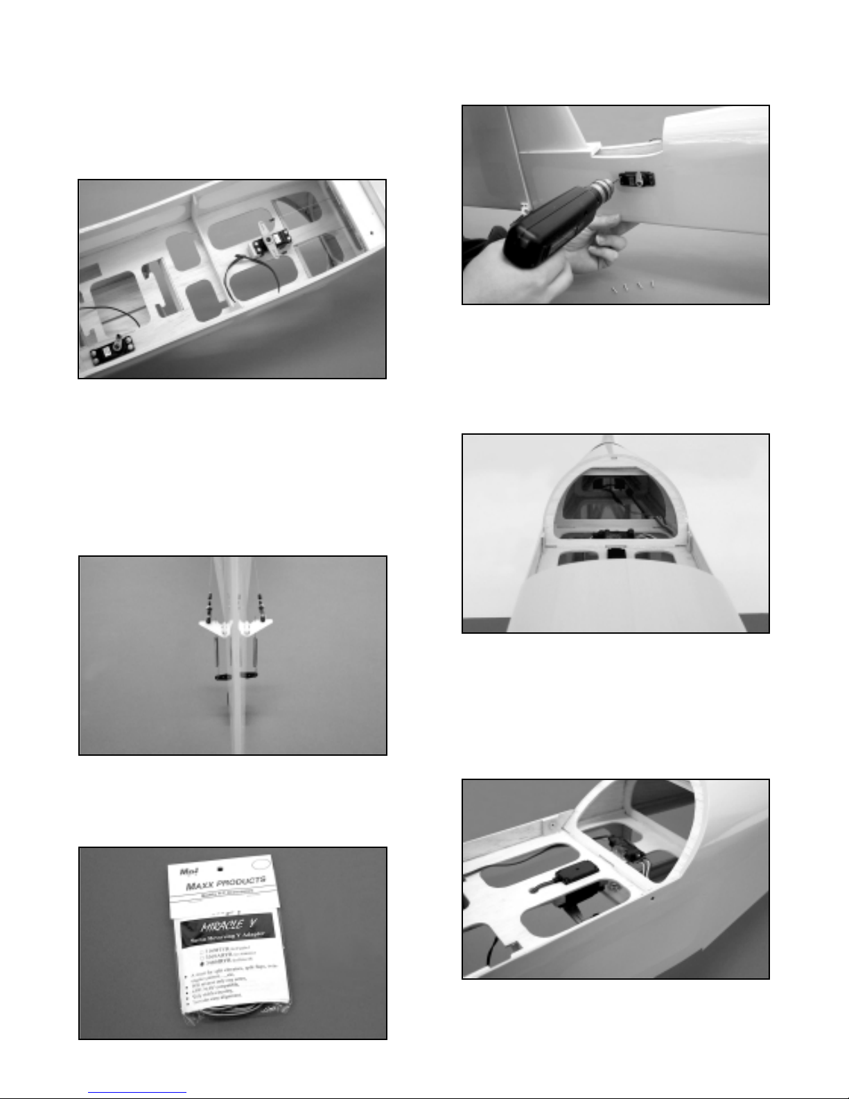
the rudder horns to approximately the same mild tension do not pull the cable tight. Remove the tape holding the
rudder in place, plug the rudder servo into your airborne
system, turn on the transmitter and test the movement
and centering of the rudder. Adjust as needed. Thread the
hex nuts back to the R/C links and tighten them to lock the
clevises in place. Be certain the output arm screw is in
place!
❑18) The two tailwheel centering springs are now attached to the
tailwheel tiller arm and the two rudder horns. Use needle
nose pliers to make a small "Z" bend at one end of each
spring. Install the "Z" bend ends to rudder horns. Apply a
small amount of tension to the spring and use the pliers to
make a 90° bend at the tailwheel tiller arm hole. Inser t the
wire into the tiller arm and make another 90° bend, creating
a "Z" bend. Do not over stretch the springs when doing this.
The springs should center the tailwheel to the rudder when
it is at neutral.
❑19) The elevator servos are now installed. As mentioned
earlier, you will either need to electronically reverse one of
these servos and use a standard Y-harness with 12"
extensions or use the "Miracle Y™" elevator splitter to
obtain "mirror image" elevator action. Install the splitter
cables through the back of the canopy hatch opening, back
to the two elevator servo cutouts. To avoid a clutter of
cables and to keep them away from the pull-pull cables,
route the extensions through the upper rear fuselage.
Connect the servos to the extension cables, securing the
connectors with tape. Mount the servo grommets supplied
with your radio system to both servos. Insert one of the
servos in place and mark it's mounting hole locations onto
the fuselage side with a felt pen. Pre-drill guide holes
(typically 1/16" dia.) for the mounting screws and repeat this
procedure on the other side of the fuselage for the
opposing servo. Install the elevator servos, securing them
with mounting screws. Use your radio system to check the
action of these servos. Make any corrections required. We
used silicon adhesive to spot glue the extension cables in
place to the upper rear of the fuselage and to mount the
"Miracle Y™" control pot, just behind the canopy base.
❑20) Pre-hinge the elevator halves by gluing their hinges in place
and preparing the horizontal stabilizer to receive the
opposite hinge ends - do not hinge elevators to the
16
Page 17
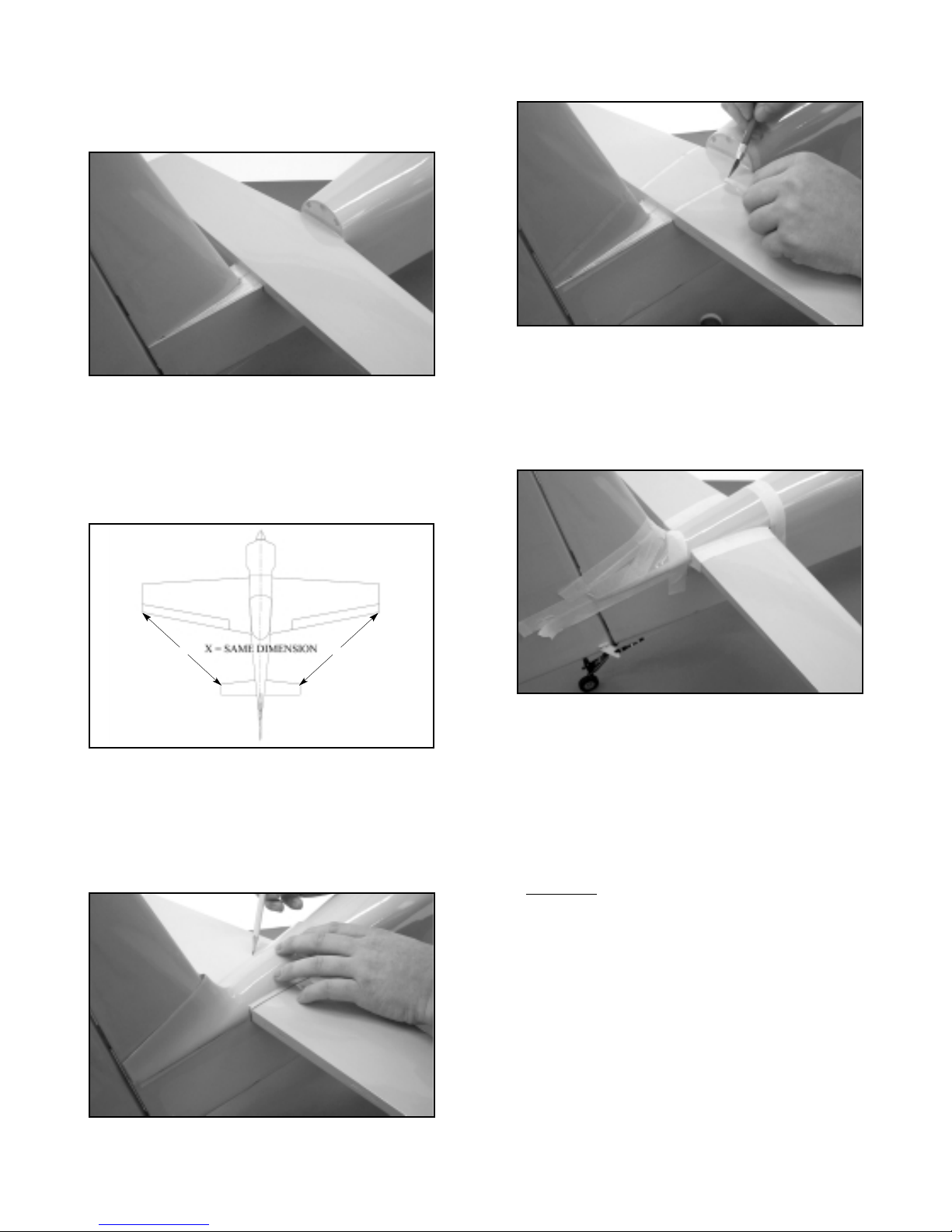
stabilizer yet.
❑21) Bolt the wing back in place to the fuselage. The hor izontal
stabilizer is now glued in place. Use only slow-cure epoxy
for this step. First set the airplane on your flat work surface
and prop the tail up to about level. Apply glue to the
fuselage stab saddle and position the stab squarely in place
- use a weight to secure it. View the airplane from the top,
front and rear, making sure the stab is square, without
leaning one way or the other. Use a ruler to measure from
the outer trailing edge wingtip back to the stab's leading
edge tip and note the measurement and repeat this process
on the opposite side. The two measurements should be the
same. Make adjustments as needed. Tape and/or weight
the stab firmly in place to the fuselage, wipe off any excess
glue with alcohol and allow the glue to set. Remove the
wing from the fuselage.
❑22) Locate the molded plastic fuselage/fin fairing. Fit the fairing
in place onto the fuselage, over the stabilizer and around
the fin to check the fit. Trim as need to seat the fairing
squarely in place, in contact with the fuselage, top of the
stabilizer and the fin. Once satisfied with the fit, mark the
location of this fairing onto the fuselage, stab and fin with a
pencil - remove the fairing. Use a sharp #11 blade to cut
away the covering just inside of the outlines just made,
exposing the wood. Apply a coat of epoxy glue to the inside
of the fairing where it will contact these areas. Fit the
fairing, pressing it firmly in place to make sure it contacts all
gluing areas. Clean up any excess glue with alcohol and
use tape to secure the faring in place. Allow the glue to
cure.
❑23) Apply petroleum jelly to the elevator hinge knuckles and
apply epoxy to the exposed hinge halves. Attach the left
and right elevator halves to the stabilizer, wiping off any
excess glue from the hinge line. Tape the elevator halves
to the stabilizer in the neutral position and allow the glue to
cure.
❑24) From the kit contents, locate the two 4-40 x 2-1/8" elevator
control rods, two 4-40 solder clevises, two 4-40 threaded
R/C links and two 4-40 hex nuts. Make two elevator
pushrod assemblies by soldering a solder clevis onto the
unthreaded
ends of the pushrods. Thread a hex nut onto
the threaded ends, followed by an R/C link.
❑25) From the kit contents, locate a right and left nylon elevator
horn and four #4 x 3/8" sheet metal screws. Remove the
wing from the airplane and turn the fuselage upside down
on your bench. The elevator horns are now installed onto
the bottoms of the elevator halv es. As mentioned, there are
plywood mounting pads in the elevator halves, inset in their
forward, inboard leading edges. Hold the horn in place on
the elevator, lined up with the elevator servo output arm,
with the holes in the horn directly over the elevator/stab
hinge line. Mark the horn mounting holes with a felt pen.
Pre-drill the hole locations with a 3/32" dia. bit. Mount the
horn in place with two #4 x 3/8" screws. Repeat this
procedure on the opposite elevator half.
Use your radio to center the elev ator servos and then mount
17
X
X
Page 18

the servo output arms in place at 90° upright. Attach the
solder clevis ends of the elevator pushrods to the servo
output arms. Adjust the threaded clevis ends to fit into the
middle hole in each elevator horn. Remove the tape
holding the elevators in neutral and test the movement
of the elevators with your radio. Adjust as required get
both elevators exactly at neutral - if you are using the
"Miracle Y™" splitter cable, you can turn the pot adjustment
to achieve neutral very easily. Final surface throw
adjustments and locking the R/C links in place with the hex
nuts will be made later.
LANDING GEAR AND WHEEL PANT ASSEMBLY
From the kit contents, locate the two 3-3/16" dia.main wheels, two
main wheel axles, two axle lock nuts, four wheel collars with lock
screws, four 4-40 x 3/8" bolts, four 4-40 blind nuts and two
fiberglass wheel pants. You will also need the aluminum landing
gear and the three M4 x 25mm mounting bolts. We also suggest
that you use Loctite® threadlocking compound on all bolts used in
the assembly of the landing gear.
❑ 1) Install the axles into the large holes at the bottom of each
landing gear leg. Thread the large lock nuts onto the
threaded ends of the axles and tighten these securely in
place to the landing gear. Slide a wheel collar onto the axle
shaft, all the way to axle's he x n ut. With the wheel collar set
screw pointing straight down, tighten the set screw to the
axle. Slide a main wheel onto the axle, followed by
another wheel collar. With the set screw pointing straight
down, tighten the set screw enough to temporarily retain the
wheel.
❑ 2) With the wheel pant slots facing inward, fit the pant in place
over the wheel - if necessary, loosen the wheel collars to
reposition the wheel to fit into the pant. The pant slot should
accept the axle hex nut. If not, rotate the hex nut with a
wrench until the pant slides in place. This is how the pants
fit to the landing gear.
❑ 3) Remove the loose wheel pants from the landing gear. Bolt
the landing gear in place to the bottom of the fuselage. Set
the fuselage on your flat workbench, with the tail supported
to approximately level. Place both wheel pants onto the
landing gear. Use a length of balsa stock (1" sq. shown) to
equally raise the rear of both wheel pants. Move the balsa
spacer to adjust the angle of the wheel pants until their
centerlines look parallel with fuselage. Hold the pant in this
position, against the landing gear. Use a 7/64" dia. drill bit,
through the two pant mounting holes, to mark the wheel
pant with the hole locations. Remove the wheel pants.
❑ 4) Use a 5/32" dia. drill bit to drill two mounting holes in the
wheel pant at the marks just made. Apply epoxy glue to the
face of two 4-40 blind mounting nuts and insert them in
place into the holes, from the inside of the wheel pant.
Wipe off any excess glue, keeping it out of the blind nut
threads.
❑ 5) Install the wheel pants to the landing gear and secure them
with the 4-40 x 3/8" bolts. Turn the landing gear assembly
upside down and use the two wheel collars to center
and space the main wheels to the pant openings. The
wheels should turn freely without obstruction. Mount the
18
Page 19
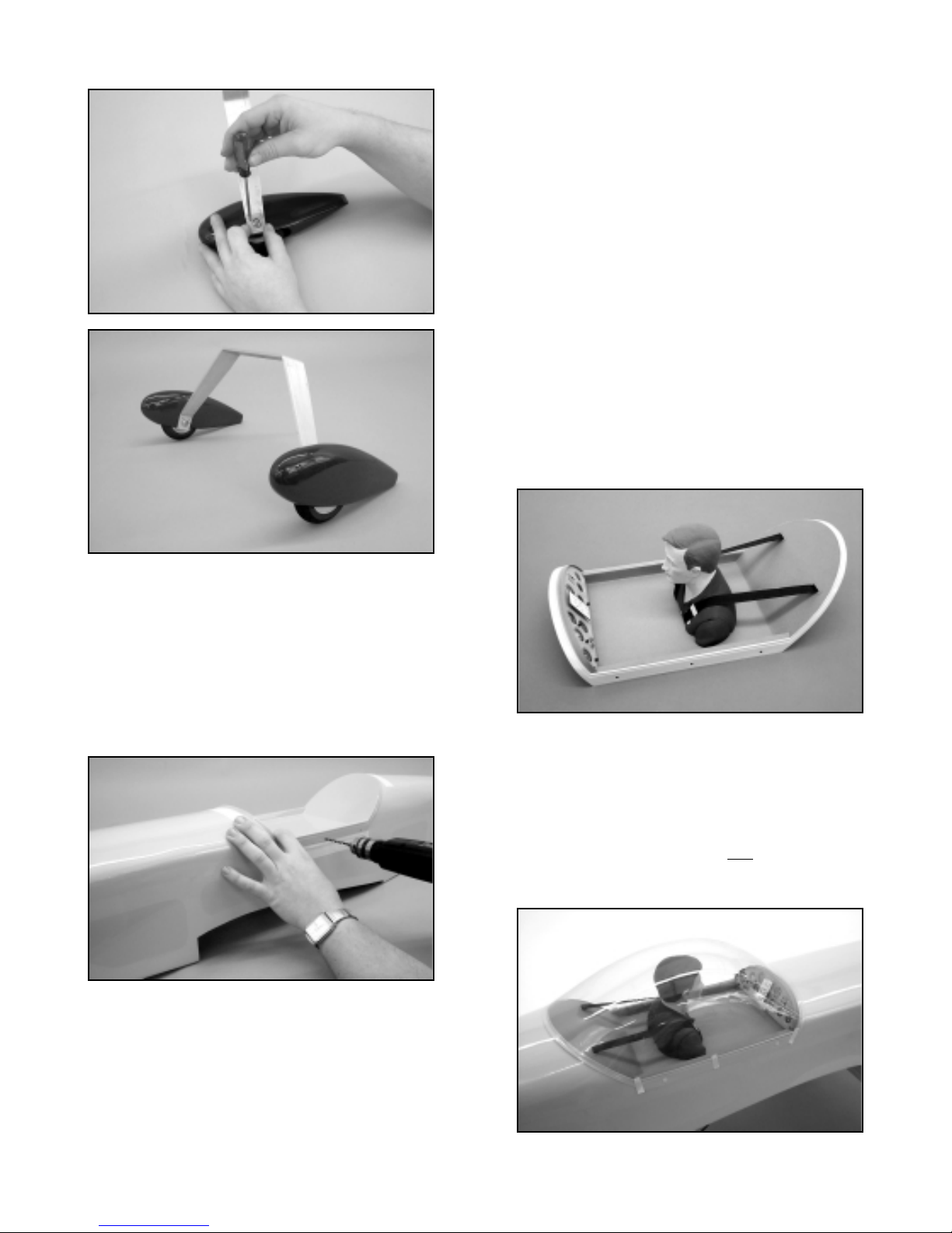
completed landing gear to the fuselage.
CANOPY AND CANOPY BASE ATTACHMENT
The molded plastic canopy base has three (3) factory drilled holes
on each side. These accept the 4-40 x 1/2" nylon mounting
bolts, used to hold it in place. Begin by using masking tape to
accurately position and secure the base in place to the top of the
fuselage. Make sure the base is firmly in place and that its front
and rear mounting lips are over the fuselage. Use a fine point felt
marker pen to mark the position of each mounting hole on both
sides of the fuselage - remove the canopy base.
From your kit contents, locate six 1/8" x 3/4" sq. plywood
mounting pads, six 4-40 x 1/2" nylon slotted bolts and six 4-40
blind mounting nuts. Center one of the plywood mounting pads
directly behind one of the hole marks just made, holding the pad
firmly to the inside of the fuselage side. Use a 7/64" dia. drill bit to
drill through the fuselage side and the plywood pad - remove the
pad. Use a 5/32" dia.bit to enlarge the hole in the pad. Apply glue
to the face of a 4-40 blind nut and press it in place into the pad.
Apply glue to the face of the pad and press it in place to
the inside of the fuselage side, with the blind nut aligned with the
drilled hole. From the outside, thread a nylon bolt in place through
the hole and into the blind nut. Screw the bolt in place, bringing the
ply pad firmly in contact with the fuselage side. Wipe off any
excess glue. Repeat this procedure for the remaining five holes.
With all holes drilled and all pads and blind nuts in place, the nylon
bolts must now be trimmed in length to clear the inside surface of
the canopy base. Use a sharp, single-edge razor blade to cut 1/4"
off of the length of each bolt.
If desired, the canopy base can now be detailed. On our
prototypes, we used light gray art paper to line the bottom and
back of the canopy base, giving it depth and color. We measured
and cut the paper to fit and applied it to the base with a heavy coat
of spray cement. We used a commercially available instrument
panel - the Hanger 9™ CAP 232 panel - mounting it with epoxy
glue. Last, we used a Hanger 9™ 1/4 -Scale Civilian pilot figure to
finish the cockpit. No matter what pilot figure you decide to use, be
sure to reinforce the bottom surface of the canopy base with a
piece of 1/32" plywood, epoxied in place. This stiffens the canopy
base and allows you to drill through the bottom of the base for
mounting screws to secure the pilot figure. We finished off the
overall look of our CAP cockpit using black twill tape to simulate
the shoulder harness restraint belts and a few pieces of light
aluminum sheet to simulate buckles and harnesses. Overall, it
looks believable and does not add much weight.
To mount the canopy, first wash it in warm sudsy water to remove
any hand oils, mold release agents, etc. Rinse and dry it
completely with a soft cloth and avoid handling the inside surface.
Use 220 sandpaper to lightly scuff the canopy base edge, where it
contacts the canopy itself. Wipe off excess dust with alcohol.
Mount the canopy base to the fuselage with the nylon bolts. Use
slow cure epoxy to mount the canopy. Mix a small amount of glue
and use a small stick to apply the glue only
to the sanded edge of
the canopy base - apply a reasonable amount but not so m uch that
it oozes. Carefully place the canopy onto the canopy base,
easing it into position. Use alcohol and a paper towel to wipe off
19
Page 20
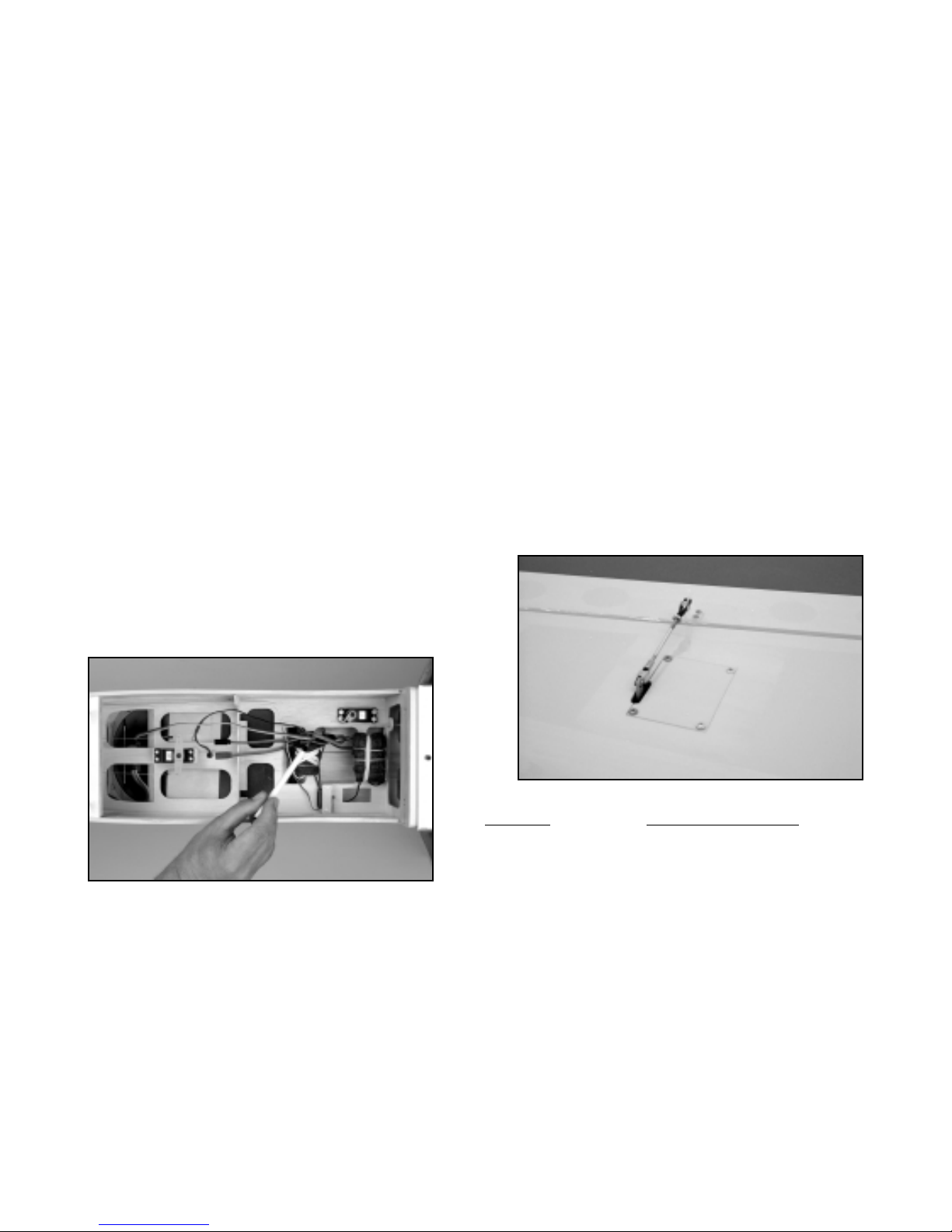
any excess glue, while lightly pressing the canopy in place to the
base. Secure the canopy to the base with pieces of masking tape
and allow the glue to cure.
When the glue has cured, remove the masking tape. The
canopy/canopy base joint can now be covered using
ULTRACOTE® matching tr im tape, available from Carl Goldberg
Models. This tape is called ULTRASTRIPE™ and is available in a
variety of widths. We suggest using the wider tape, such as the
3/16" or 1/4".
RADIO INSTALLATION
With the servos now installed with the correct extensions in place
and secured, all that remains is the installation of the receiver,
battery pack and switch. Remember that the single heaviest unit
in this system is the battery pack. This means that you can, if
needed, locate the batteries wherever they are required to achieve
the correct CG. When mounting the receiver and battery pack, first
wrap them in foam and use rubber bands and/or tie-wraps to
secure them in the fuselage. This allows these units to be easily
accessed and repositioned if necessary. The switch can be
mounted onto the fuselage side or internally. We prefer an
internally mounted switch. We mounted ours onto the radio tray,
using a length of music wire to activate the switch from the outside .
This is simple to do. Just drill a small diameter hole in the switch
lever to fit a piece of .045 music wire. Drill an exit hole in the side
of the fuselage, lined up with the switch/wire location. Make a 90°
bend in one end of the wire and insert the shor t end into the hole
in the switch. Apply silicon glue to one side of the switch and insert
the wire through the hole in the fuselage, pressing the switch
firmly to the radio tray. Make another 90° bend in the wire outside
of the fuselage, giving you a small "handle" to pull and push when
activating the on/off switch. Besides looking neat, this method
provides protection to the switch from dirt, debris and exhaust.
When mounting the receiver, note that we have provided the CAP
with an internal antenna exit tube. When viewed from the wing
saddle (fuselage upside down) this tube is located on the right side
of the fuselage, extending from the radio tray back through the
fuselage, exiting just ahead of the tailwheel assembly on the
bottom. Thread your antenna through this tube when installing
your receiver.
All servo, switch, and battery connections to the receiver are now
made. The aileron Y-harness stays plugged into the receiver
aileron channel receptacle, with the two connecting ends hanging
loose for wing attachment. Turn the radio system on and check the
functions of the throttle, elevator and rudder servos. These should
all now be centered and working perfectly, without any binding.
Correct any such problems now. Plug your aileron servo
leads into the Y-harness connectors and mount the wing to the
fuselage. Test the action of the aileron servos, adjusting the
linkages as needed to center them. Make sure the ailerons are
traveling in the proper direction to provide left and right roll. With
everything checked and working, now is the time to set the initial
control movements.
CONTROL MOVEMENTS
This is an important section of this manual. After flying your
CAP231EX for awhile, getting used to its characteristics, you will
likely change the control throws to suit your style of flying. But you
have to start somewhere and this is where you begin. These
movements provide the CAP with very smooth control inputs
without the immediate need for expotential. We suggest starting
out with these movements as your low and high rates. Note that
we do not suggest full rudder throw initially. This is because the
rudder is very large and aerodynamically powerful. So powerful
that it can fly the airplane in knife-edge flight even at fairly low
throttle settings. At full throw, the rudder can also toss the CAP
very deeply into snap maneuvers, literally slowing it down. Rudder
throw is something you can easily play with after you are more
comfortable with the airplane, especially for 3-D type flying.
Last, after setting the controls for these surface movements, make
sure each clevis has a length of fuel tubing in place to prevent it
from coming disconnected from either the control horns or the
servo output arms. Also be sure you have tightened each of the
4-40 hex nuts tightly against all threaded R/C links, locking them in
place.
SURF
ACE SUGGESTED THROWS
AILERONS: LOW RATE: 3/4" UP - 3/4" DOWN
HIGH RATE: 7/8" UP - 7/8" DOWN
ELEVATORS: LOW RATE: 1-3/8" UP - 1-3/8" DOWN
HIGH RATE: 1-3/4" UP - 1-3/4" DOWN
(MEASURED AT INBOARD TRAILING EDGE)
RUDDER: 3" RIGHT - 3" LEFT
(MEASURED AT WIDEST,
LOWER TRAILING EDGE)
THROTTLE: FULL MOVEMENT
DECAL APPLICATION
The decal set provided with your CAP is truly a work of art. These
decals are adhesive-backed Mylar, NOT water activated transfers.
These decals are not die-cut and require that you cut them from
20
Page 21
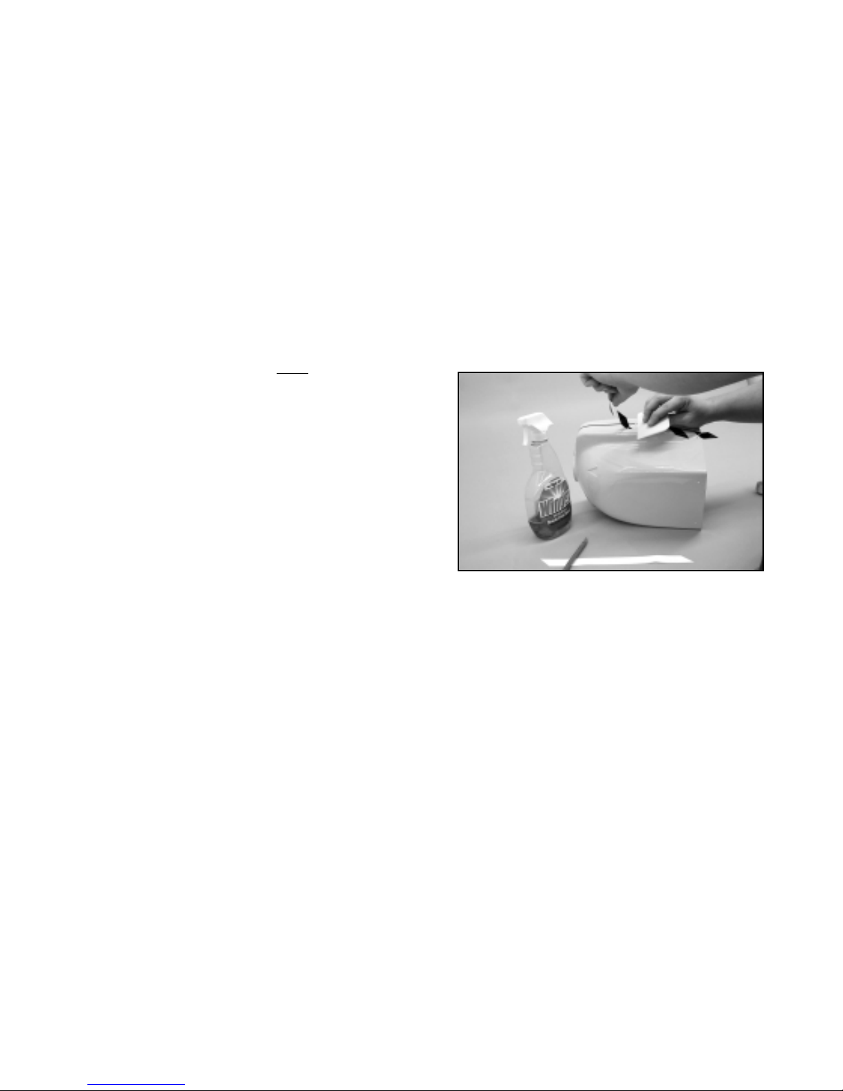
their sheets with a sharp #11 blade or good pair of scissors. Note
that every decal on all three sheets is numbered. These numbers
correspond to the CAP 231EX 3-view line drawing on the last page
of this manual, providing you with their placement locations - Note:
The 3-view drawing provided is NOT scale and should not be used
for documentation. Use this drawing, as well as the box art, to
locate your decals accurately.
Since these decals are large and because the adhesive is very
aggressive, it is important that you use the proper technique
in applying them to your model. DO NOT deviate from this
procedure. Doing so may ruin the decals. Following this
procedure will allow you to easily place the decals in their proper
locations and permanently adhere them to the model. Once in
place, these decals stand up well to day-to-day flying use and are
resistant to fuel exhaust. With reasonable care, they will look good
for a very long time.
You will need a good glass cleaner, such as Windex®, a supple
squeegee (the SIG 4" Epoxy Spreader, #SIGSH678 is perfect for
this job), clean, soft cloths (old tee shirts are great), a good straight
edge, a ruler and a hobby knife with shar
p #11 blades. For
application of the larger decals, such as the wing, fuselage, stab,
etc., we suggest that you also have some trim tape handy for
temporary guidelines - 1/8" width or so is perfect.
Begin with the wings. Use a flat, clean work surface to cut out the
two wing decals, #1. Cut the decals as closely to the graphic as
possible, using a straight edge for the long cuts. With the decals
ready, use a long length of striping tape to locate the top edge of
the decals on the wing. Do this by stretching the tape from one
wingtip to the other. With the tape aligned and lightly pressed in
place, the decals can now be applied. Carefully peel and remove
the decal from its sheet, suspending it in the air with your fingers.
Spray Windex® on the adhesive side of the decal and then onto
the wing, where the decal will be applied. Apply enough Windex®
to create a true film on the wing surface. Place the decal
carefully onto the wing - do not press. Slide the decal accurately
in place, lightly smoothing any wrinkles with your fingertips. Once
the decal is in position, use the squeegee to begin lightly pressing
the decal in place, while holding it to the wing with your fingers.
Take your time and use progressively heavier pressure to remove
the Windex® from beneath the decal. As the Windex® is forced
out from beneath the decal, the adhesive will take hold and make
the decal difficult to move. Carefully continue using the squeegee,
removing any bubbles and making sure the decal edges are
firmly in place. Remove the guideline striping tape from this half
of the wing. Use a soft clean cloth to gently wipe away any
remaining liquid from the wing panel - always wipe away from
decal edges, never into them. Repeat this process with the
remaining wing decal. This is the basic procedure for applying all
of the remaining decals to the model.
The fuselage sides, including the cowl, also require the use of
striping tape to align the top edges of the decals accurately , as w ell
as to align them correctly from one side to the other. To do this,
take a careful look at the 3-view drawing and the photographs of
the actual model. These will help you understand where the decals
are to be placed. When placing the striping tape guide on the
fuselage, have the cowl in place and the rudder taped to
neutral. Once the striping tape is placed along the entire length of
the fuselage, rudder and cowl, carefully cut the tape at the rear
edge of the cowl and remove the cowl. The checkers will be
applied to the cowl, off the fuselage but you will already have the
guideline accurately in place. We also found it easiest to apply the
rear checkers (#6 and #18) to both the fuselage and rudder in one
piece, using the squeegee to set them in place. Then use a #11
blade to cut and trim them at the hinge line.
Applying the decals to the cowl is not difficult. Start with the top
run of checkers - #22 (left side) and #15 (right side). These are
placed on the cowl to match the fuselage checker, along the tape
guide to the front. Use the squeegee to rub them in place,
wrapping the rear edge around and into the inside of the cowl.
Next, apply the bottom cowl check ers, #23 (left side) and #16 (right
side) in the same manner, aligning their rear edges with the
corresponding checker on the fuselage. Note that when viewed
from the side, this bottom course of checkers is parallel with the
top course. Use the squeegee to r ub the checkers in place. Next
use the #11 blade to carefully cut out the clear portion of these
cowl checkers, using the knife to lift an edge, peeling them away
from the cowl. This leaves only the dark checks accurately in
place. Finally, apply the center checkers, #CL-1, 2, 3, and 4 (left
side) and #CR-1, 2, 3, and 4 (right side). These are applied
individually, with their corners aligned with the top and bottom
checkers. Despite the small compound curves, these center
checkers will lay flat nicely when applied with the squeegee.
When all decals are in place, use a soft cloth to carefully wipe them
dry, as well as the rest of the model. Carefully check all decal
edges and corners, using the squeegee to burnish them firmly in
place. Leave the model alone and avoid handling for a few hours.
This allows the decal adhesive to set and any residual liquid to
evaporate. Although usually not necessary, decal edges can be
further protected by applying clear epoxy paint with a small brush,
to seal them. For perspective, our prototypes have been flown
extensively and used at tradeshows and the decals still look great!
ESTABLISHING BALANCE
In terms of success, this is probably the single most important step
in preparing your CAP for flight. The final placement of the
longitudinal Center of Gravity for this model is extremely important
and should be approached with patience and care.
Completely assemble the model, including propeller, spinner, etc.
DO NOT fill the fuel tank for balancing purposes. Once the model
is assembled, as it would be for flight, you need to find where it
balances in this unadjusted condition. This is easiest to do by
turning the fully assembled model upside down and using a
balancing fixture. We make our own balancing fixtures with a
couple of 1/4" dia.dowels glued into a fairly substantial wood base,
at perpendicular 90° angles. The dowels need to be the same
length and tall enough to accommodate the height of the
assembled CAP, as well as the width of the fuselage, plus about
1/4" to 1/2" additional width. The tops of the dowels need to be
padded to avoid damage to the wing. We used 1/8" thick rubber
sheet, cut to 1/4" diameter, glued in place, for the padding. There
21
Page 22
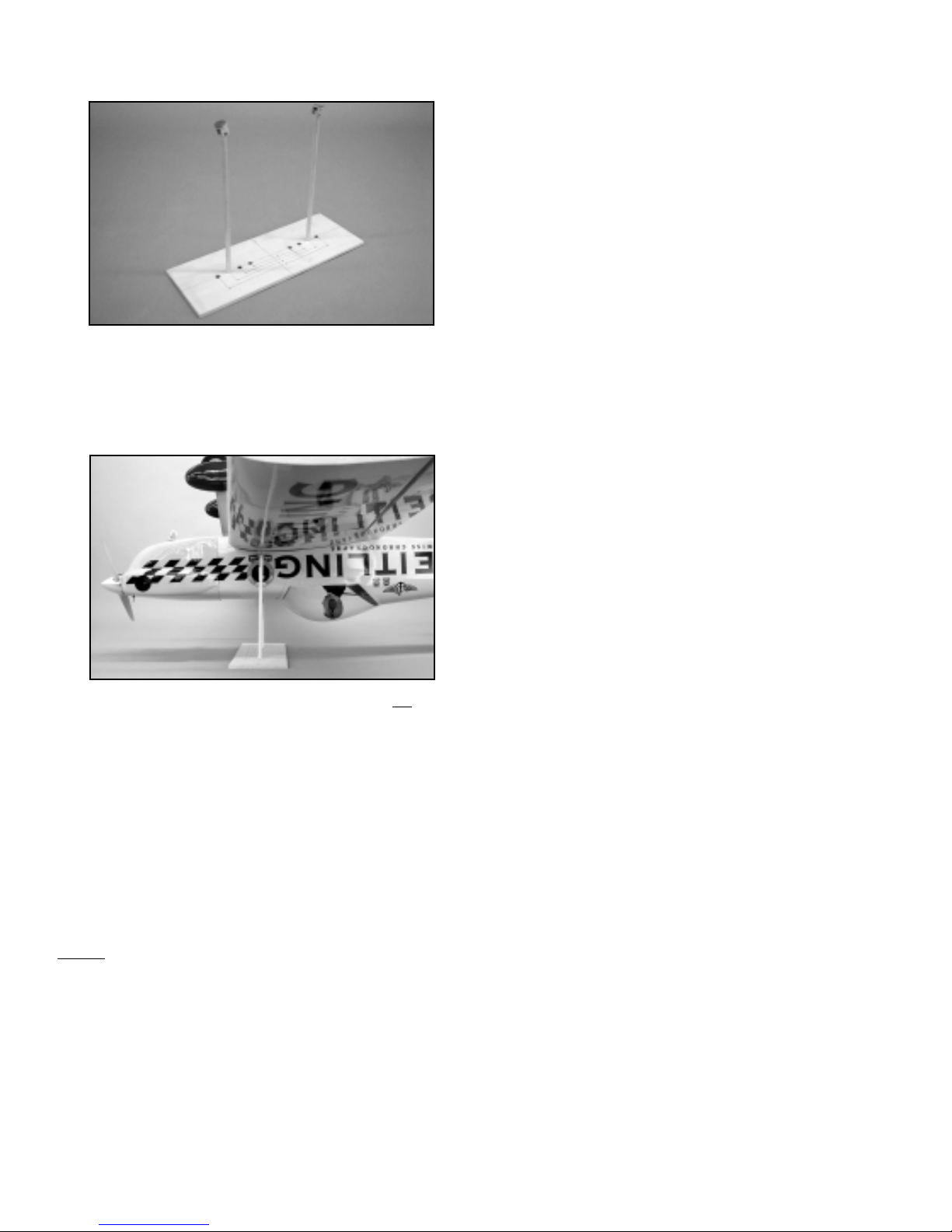
are commercial units available for balancing but be sure they are
large enough to support the weight and size of the CAP.
For initial test-flying and familiarization purposes, we suggest a
starting balance point of 4" behind the inboard leading edge of the
wing. 4" equals 27% of MAC (Mean Average Chord). For
reference, a balance point of 4-1/2" behind the wing's inboard L.E.
equals 30% of MAC and 4-15/16" behind the L.E. equals 33.3%
of MAC.
As we all know, as the CG is moved aft, the airplane will
become
more proactive in pitch. We have flown the CAP at the 30%
location and found it to be manageable, with excellent aerobatic
capabilities. However, we did notice an increase in pitch
sensitivity and decreased the elevator throw to compensate (from
3/4" each way on low rates to 5/8" each way). "Softening"
elevator response with a reasonable expotential percentage also
works. As stated, the CAP has very powerful flying surfaces and
the elevators are no exception. We therefore suggest that you
begin with the 27% CG location.
The best means of shifting the CG fore or aft is to locate the
battery pack where it is needed to achieve balance. If doing this
does not work and more weight is needed, consider using a
larger (and therefore heavier) battery pack. Try to avoid adding
useless
weight. If you need more weight in the nose, try a
heavier spinner or replace the light wheels with heavier aftermarket wheels. If your model is nose heavy and battery shifting
does not work, you can make significant changes in balance with
lead stick-on weights. These are unsightly but should be
considered until such time as you have flown the model and are
happy with the CG. Once that's done, the weights can be placed
inside the fuselage by simply removing the elevator servos and
placing the weights inside and securing them. With the elevator
servos back in place, the weights are hidden. For reference, our
CAPs, using either the Irvine 1.20 or 1.50 and also, the Saito 1.50
4-strokes, required no additional weight to achieve balance.
Finally, the flight performance of your CAP will benefit greatly by
dynamically balancing it. Dynamic balancing requires that the
model be suspended upside down, using substantial chord or
fishing line. Loop the line over the engine propeller shaft and the
other end over the tailwheel brack et. Hang the model from the ceiling or a rafter, leveling it in side view. With the model secured in
this way, observe the wings. Ideally they should be level,
without one wing lower than the other. If one panel is lower, it
means that it is somewhat heavier than the other. When
flying the model, this uncorrected imbalance may cause the model
to "pull" to the heavy side, especially in up line maneuvers. To
make the airplane track true, the light panel needs weight to
balance it level with the other panel. Again, this can be done with
stick on weights, which could later be hidden. Always secure
weights firmly in place.
FLYING
If you have carefully followed this assembly manual, you should
have no real problems in test flying your CAP 231EX. Make
yourself a simple checklist to assure your attention to the following
important pre-flight issues:
Try to choose a calm day for the first flight. Good conditions will
help in correctly evaluating the flight performance of this model.
Begin your test flight by making sure the engine needle valves are
properly set, providing a reliable idle, a strong top end and smooth
transition performance. We always set our engines to run a little
on the rich side and suggest you do the same.
22
¥ Radio system is fully charged - both transmitter and
airborne pack
¥ Each link on all flying surfaces has been checked and has
jam nuts and safety tubes in place
¥ All metal bolts have had an application of Loctite¤ to
secure them
¥ Nylon bolts holding cowl and canopy hatch are securely in
place
¥ All three wheels roll freely and the airplane rolls straight
when in neutral
¥ All servos checked for output arm screws
¥ All servos securely in place - no loose mounting screws,
bolts, etc.
¥ All servo extension connectors securely taped
¥ All controls work smoothly with no binding, rubbing, etc.
¥ Battery pack secured in fuselage
¥ Receiver wrapped in foam and secured in fuselage
¥ Switch securely in place
¥ Fuel system checked and working
¥ Engine well broken in and reliable
¥ Spinner and propeller are securely in place
¥ Propeller in good condition and properly balanced with no
nicks, cracks, etc.
¥ CG is at location recommend in these instructions
¥ Flying surfaces set at prescribed movements per the
information provided in this manual
¥ Per AMA, your name, address and telephone number is
taped to inside of model
¥ Radio range check to be performed at the flying field
Page 23
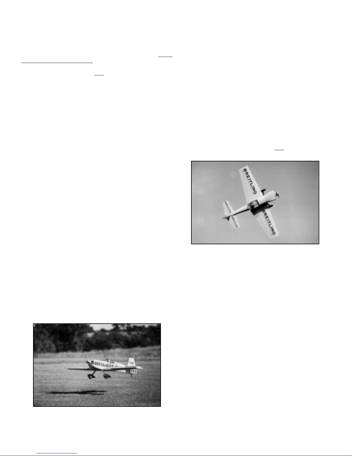
Holding up elevator, taxi the model to get a feel for how it handles
on the ground. Make sure you have positive left and right turning
ability. If not, make any adjustments needed to achieve positive
ground control. Once you are satisfied with the taxi tests, line the
model up with the centerline of the runway, nose into the wind.
Hold a little up elevator and advance the throttle smoothly - do not
run the throttle up all at once! The airplane should roll forward
smoothly , tailwheel on the g round. As speed builds, slowly back off
the elevators and use just a little
rudder, only as needed, to
maintain a straight takeoff run. The tail will come up as flying
speed is reached and a little up elevator will lift the CAP off the
ground.
Maintain a straight outbound flight path, climbing at a shallow
angle until a safe maneuvering altitude is reached. If the model
requires trim, fly it to a reasonable altitude first before trimming.
Initially, make your control inputs smooth and avoid jerking the
sticks.
At altitude, make any trim changes needed to achieve hands off,
straight and level flight. From our experience, this will take very
little trim input, if the model was assembled and balanced
according to this manual. Once you're comfortable, make a few
circuits around the field to get the feel of the controls. The airplane
should demonstrate smooth flight characteristics without
jumpiness or over-sensitivity. At altitude, try a roll. Then try
another roll to the opposite side. Properly trimmed, the CAP will
roll smoothly and very axially in either direction. Now try a loop.
The CAP should pull cleanly through loops, without wandering to
either side. Once you're comfortable, try knife-edge flight. You will
quickly find that the CAP has little or no pitch/roll coupling and that
it easily maintains altitude with just a little rudder input! You will
also discover that your CAP has outstanding inverted flight
characteristics. Our prototypes require only the smallest amount
of down elevator to maintain level inverted flight!
Assuming you're comfortable and getting used to the airplane, take
it to a safe altitude and throttle back to get a feel for the slow flight
and stall characteristics. Properly balanced and trimmed, your
CAP should demonstrate fairly sedate, no fuss stall
characteristics. Once flying speed and up elevator input is bled off,
the CAP should just drop its nose and resume flying as speed
picks up. All of this is great information to have when you are
setting up the first landing.
Landing the CAP is a pleasure. We like to keep a little power on
the engine during final approach, down to a few f eet off the ground.
We typically back completely off the throttle once the
airplane is low to the ground with a good rate of descent
established. Flair the airplane as the ground approaches for a
smooth 3-point landing and rollout. Hard landings are not
necessary, sound piloting skills are.
The second flight should be even more fun because you have by
now inputted any required trims learned from the first flight. Before
flying again, check the airplane for anything that may have come
loose, become disconnected, etc. This is good practice and tends
to insure a long life for the model.
As you become more familiar with your CAP, you are going to
discover its ability to perform aerobatics. The CAP 231EX is an
elegant aerobatic machine with seemingly endless capabilities. As
mentioned earlier, you will quickly discover that your CAP has a
powerful rudder. If you want to, you'll find it fairly easy to make
climbing knife-edge passes at fairly low throttle settings. In fact, if
your radio has expotential capability on the rudder channel, you
may want to tone the rudder action down a little around center, to
suit your style of flying. For those of you interested in using your
CAP for 3-D aerobatics, set up your radio to take advantage of the
huge control movements available from this model. However, we
would urge you to "sneak up" on such control throws, making very
sure you have them available to you only
on your high rate
switches!
We are sure that you will enjoy your CAP 231EX for a long time to
come. Please fly the model safely with constant regard to other
fliers, spectators, and property. Good luck and good flying!
FINIS
23
Page 24

24
MANUFACTURER'S INDEX:
PRODUCT
SOURCE
RD-6000 COMPUTER RADIO SYSTEM AIRTRONICS, INC.
and 1185 Stanford Court
HEAVY DUTY SERVOS Anaheim, CA 92805
ULTRACOTE¤ and ULTRASTRIPE“ CARL GOLDBERG MODELS, INC.
4734 West Chicago Avenue
Chicago, IL 60651
KWIK-FILL FUELING VALVE - #334 DU-BRO PRODUCTS, INC.
and 480 Bonner Road
SUPER STRENGTH SERVO ARMS P.O. Box 815
Wauconda, IL 60084
SAITO ENGINES HORIZON HOBBY DISTRIBUTORS
and 4105 Fieldstone Road
1/4 SCALE CIVILIAN PILOT Champaign, IL 61822
HANGER 9“ #HAN8275
and
INSTRUMENT PANEL
HANGER 9“ #HAN177
"MIRACLE Y“" ELEVATOR SPLITTER MAXX PRODUCTS
and 815 Oakwood Road Unit D
LARGE CAPACITY BATTERY PACKS Lake Zurich, IL 60047
and Tel: (847) 438-2233
AFTER MARKET Y-HARNESSES Fax: (847) 438-2898
INCIDENCE METER ROBART MFG., INC.
P.O. Box 1247
St. Charles, IL 60174
CAP 231EX DOCUMENTATION SCALE MODEL RESEARCH
FOTO-PAAK #5444 3114 Yukon Avenue
Costa Mesa, CA 92626
Tel: (714) 979-8058
Fax: (714) 979-7279
IRVINE ENGINES SIG MANUFACTURING COMPANY, INC.
and 401-7 South Front Street
CAP CUSTOM IN-COWL MUFFLER Montezuma, IA 50171-0520
(P/N IRV120150M) Order Line: (800) 247-5008
and
EPOXY SPREADER/SQUEEGEE
(P/N SIGSH678)
Page 25
25
LIMIT OF LIABILITY
The craftsmanship, attention to detail, and actions of the builder/flyer of this model airplane kit will
ultimately determine the airworthiness, flight performance, and safety of the finished model. SIG MFG.
CO. s obligation shall be to replace those parts of the kit proven to be defective or missing. The user shall
determine the suitability of the product for his or her intended use and shall assume all risk and liability in
connection therewith.
CUSTOMER SERVICE
SIG MANUFACTURING CO. is totally committed to your success in both assembling and flying the
CAP 231EX ARF kit. Should you encounter any problem building this kit, or discover any missing or
damaged parts, please feel free to contact us by mail or telephone.
SIG MANUFACTURING COMPANY, INC.
401-7 South Front Street
Montezuma, IA 50171-0520
SIG MODELER S ORDERLINE: 1-800-247-5008
(to order parts)
SIG MODELER S HOTLINE: 1-641-623-0215
(for technical support)
SIG WEB SITE: www.sigmfg.com
WARNING! THIS IS NOT A TOY!
Flying machines of any form, either model-size or full-size, are not toys! Because of the speeds that
airplanes must achieve in order to fly, they are capable of causing serious bodily harm and property
damage if they crash. IT IS YOUR RESPONSIBILITY AND YOURS ALONE to assemble this model
airplane correctly according to the plans and instructions, to ground test the finished model before each
flight to make sure it is completely airworthy, and to always fly your model in a safe location and in a safe
manner. The first test flights should only be made by an experienced R/C flyer, familiar with high
performance R/C aircraft.
The governing body for radio-control model airplanes in the United States is the ACADEMY OF MODEL
AERONAUTICS, commonly called the AMA. The AMA SAFETY CODE provides guidelines for the safe
operation of R/C model airplanes. While AMA membership is not necessarily mandatory, it is required by
most R/C flying clubs in the U.S. and provides you with important liability insurance in case your R/C model
should ever cause serious property damage or personal injury to someone else. For more information,
contact:
ACADEMY OF MODEL AERONAUTICS
5151 East Memorial Drive
Muncie, IN 47302
Telephone: (765) 287-1256
Page 26
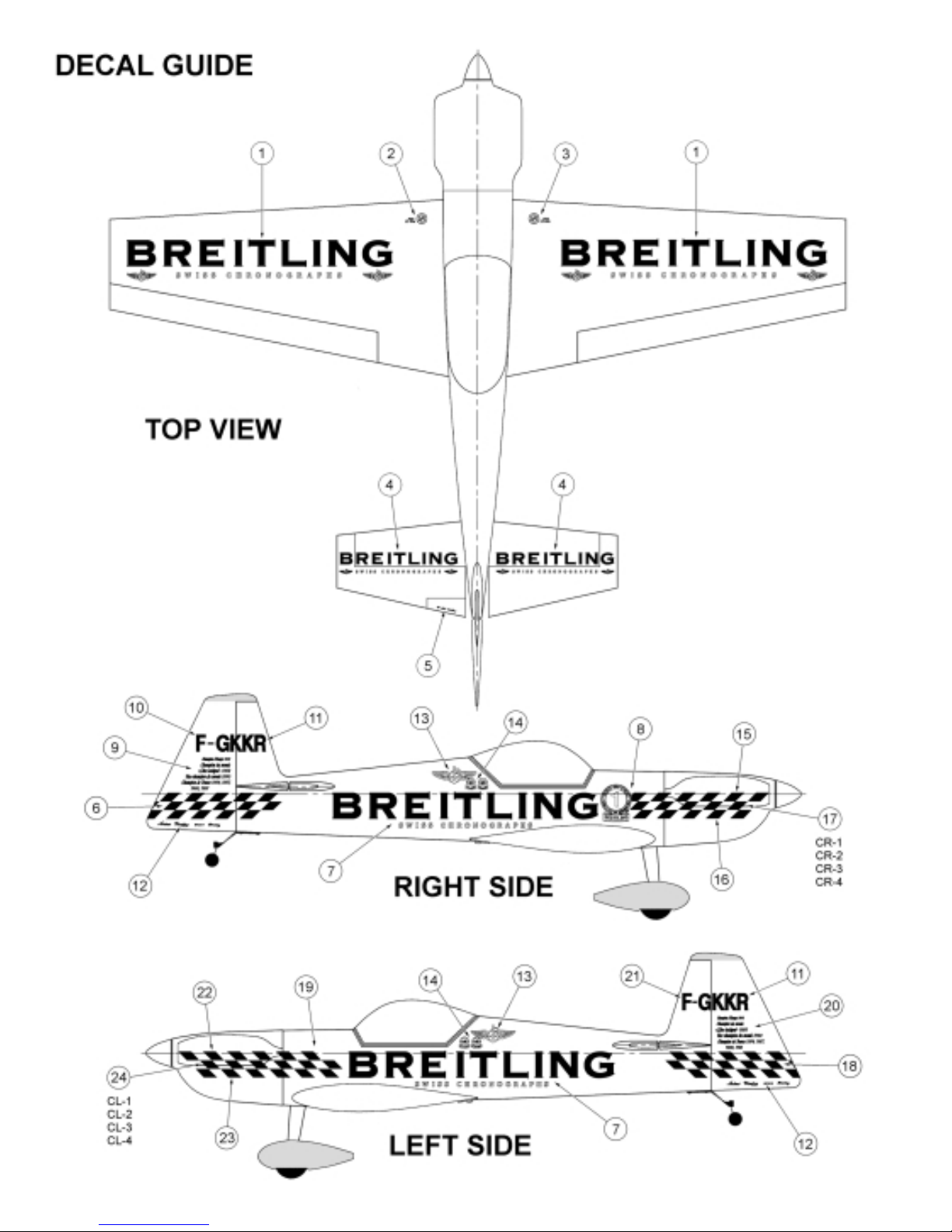
 Loading...