

Page 1

SMAC3 User Material
SMAC3
User Manual
Version 1.0
1
Page 2

Table of Contents
1 Introduction
1.1 About This User Guide 5
1.2 FCC User Information 6
1.3 Professional Antenna Installation Instructions 7
1.4 Typical Outdoor Installation of Radios 7
1.5 Certified Antenna Gain and Tx Power values 8
1.6 Safety Precautions 10
1.7 Product Overview 11
1.8 Product Key Features 12
2 Device Configuration
2.1 Power On-Device 12
2.2 PC Configuration 13
2.3 Device Access Types 13
2.4 Login Process 14
2.5 Quick Configuration 16
2.6 Graphical User Interface 17
SMAC3 User Material
3 Quick Start
3.1 System 18
3.1.1 IP Configuration 19
3.1.2 VLAN Configuration 19
3.2 Location 21
3.3 5 GHz Radio Configuration 21
3.4 2.4 GHz Radio Configuration 23
3.5 Site Survey 23
3.6 Link Statistics 24
4 Wireless Configuration
5 GHz Radio Configuration 25
4.1 Properties 25
4.2 MIMO 27
4.3 DDRS /ATPC 27
4.4 Security 28
4.5 MAC-ACL 28
4.6 DCS (Dynamic Channel Selection) 29
2.4 GHz Configuration 30
4.7 Properties 30
4.8 Security 31
4.9 MAC-ACL 31
2
Page 3

5 Network
5.1 IP Configuration 32
5.2 Radius 33
5.3 Static Routes 34
5.4 VLAN 35
5.5 Ethernet 36
5.6 DHCP Server 37
5.6.1 5 GHz Radio 37
5.6.2 2.4 GHz Radio 37
5.7 DHCP Fixed Leases 38
5.8 Filtering 38
6 Management
6.1 System Configuration 39
6.1.1 General 39
6.2 Logging 40
6.2.1 System log 40
6.2.2 Temperate log 40
6.3 Location 41
6.4 Services 41
6.4.1 HTTP 41
6.4.2 Telnet/ SSH 41
6.4.3 SNMP 41
6.5 Upgrade/Reset 42
6.5.1 HTTP 42
6.5.2 TFTP 43
6.5.3 Reset 44
SMAC3 User Material
6.1.1.1 NTP 39
6.1.1.2 GPS 39
6.1.1.3 Dying Gasp 39
6.5.1.1 Backup & Restore 42
6.5.1.2 Upgrade Firmware 42
7 Monitor
7.1 Statistics 44
7.1.1 5 GHz Radio 44
7.1.2 2.4 GHz Radio 45
7.1.3 Wireless 46
7.1.4 Ethernet 47
7.2 LAN Table 47
7.2.1 Bridge 47
7.2.2 ARP 48
7.3 Logs 48
3
Page 4

SMAC3 User Material
7.3.1 Wireless 49
7.3.2 Ethernet 50
7.3.3 System 51
7.3.4 Configuration 51
7.3.5 Reboot 52
7.4 Live Traffic 52
7.4.1 Live connection 52
7.4.2 Traffic 53
7.5 Tools 53
7.5.1 Diagnostics 53
7.5.2 Site Survey 54
7.5.3 Spectrum Analyzer 55
7.6 Technical Specifications 56
4
Page 5

1 Introduction
1.1 About This User Guide
This guide describes the planning, installation, configuration and operation of the SIFY
Networks point-to-point and point-to-multipoint wireless radios. It covers SMAC3 KEY. It is
intended for use by the system designer, system installer and system administrator.
SMAC3 User Material
Introduction
Device Configuration
Quick Guide
Wireless
Network
Management
SIFY TECHNOLOGIES LIMITED
2nd Floor, Tidel Park
4. Rajiv Gandhi Salai, Taramani
Chennai – 600 113
Phone: +91 44 2254 0770-77
Fax: +91 44 2254 077
5
Page 6

SMAC3 User Material
1.2 FCC User Information
Federal Communication Commission Interference Statement
This device complies with Part 15 of the FCC Rules. Operation is subject to the following
two conditions: (1) This device may not cause harmful interference, and (2) This device
must accept any interference received, including interference that may cause undesired
operation.
This equipment has been tested and found to comply with the limits for a Class B digital
device, pursuant to Part 15 of the FCC Rules. These limits are designed to provide
reasonable protection against harmful interference in a residential installation. This
equipment generates uses and can radiate radio frequency energy and, if not installed and
used in accordance with the instructions, may cause harmful interference to radio
communications. However, there is no guarantee that interference will not occur in a
particular installation. If this equipment does cause harmful interference to radio or
television reception, which can be determined by turning the equipment off and on, the
user is encouraged to try to correct the interference by one of the following measures:
Reorient or relocate the receiving antenna.
Increase the separation between the equipment and receiver.
Connect the equipment into an outlet on a circuit different from that to which the
receiver is connected.
Consult the dealer or an experienced radio/TV technician for help
FCC Caution: Any changes or modifications not expressly approved by the party responsible
for compliance could void the user's authority to operate this equipment. This transmitter
must not be co-located or operating in conjunction with any other antenna or transmitter.
Radiation Exposure Statement:
This equipment complies with FCC radiation exposure limits set forth for an uncontrolled
environment. This equipment should be installed and operated with minimum distance
165cm between the radiator and your body.
6
Page 7

SMAC3 User Material
1.3
Professional Antenna Installation Instructions
Installation Personal
This product is designed for specific application and needs to be installed by a qualified
personal who has RF and related rule knowledge. The general user shall not attempt to install
or change the setting. For complete RF test reports and regulatory power limits, please see
documents under FCC-ID: Q5A-SMAC-5700
Installation Location
The product shall be installed at a location where the radiating antenna can be kept 165cm
from nearby person in normal operation condition to meet regulatory RF exposure
requirement.
External Antenna
Use only the antennas which have been approved in section Certified Antennas. The nonapproved antenna(s) may produce unwanted spurious or excessive RF transmitting power
which may lead to the violation of FCC limit and is prohibited.
Warning
Please carefully select the installation position and make sure that the final output power does not exceed
the limit set force in relevant rules. The violation of the rule could lead to serious federal penalty.
It is the responsibility of the installer to ensure that when configuring the radio in the United States (or
where FCC rules apply), the Tx power is set according to the values for which the product is certified. The
use of Tx power values other than those, for which the product is certified, is expressly forbidden by FCC
rules 47 CFR part 15.204.
It is the responsibility of the installer to ensure that when using the outdoor antenna kits in the United
States (or where FCC rules apply), only those antennas certified with the product are used. The use of any
antenna other than those certified with the product is expressly forbidden by FCC rules 47 CFR part 15.204.
7
Page 8
SMAC3 User Material
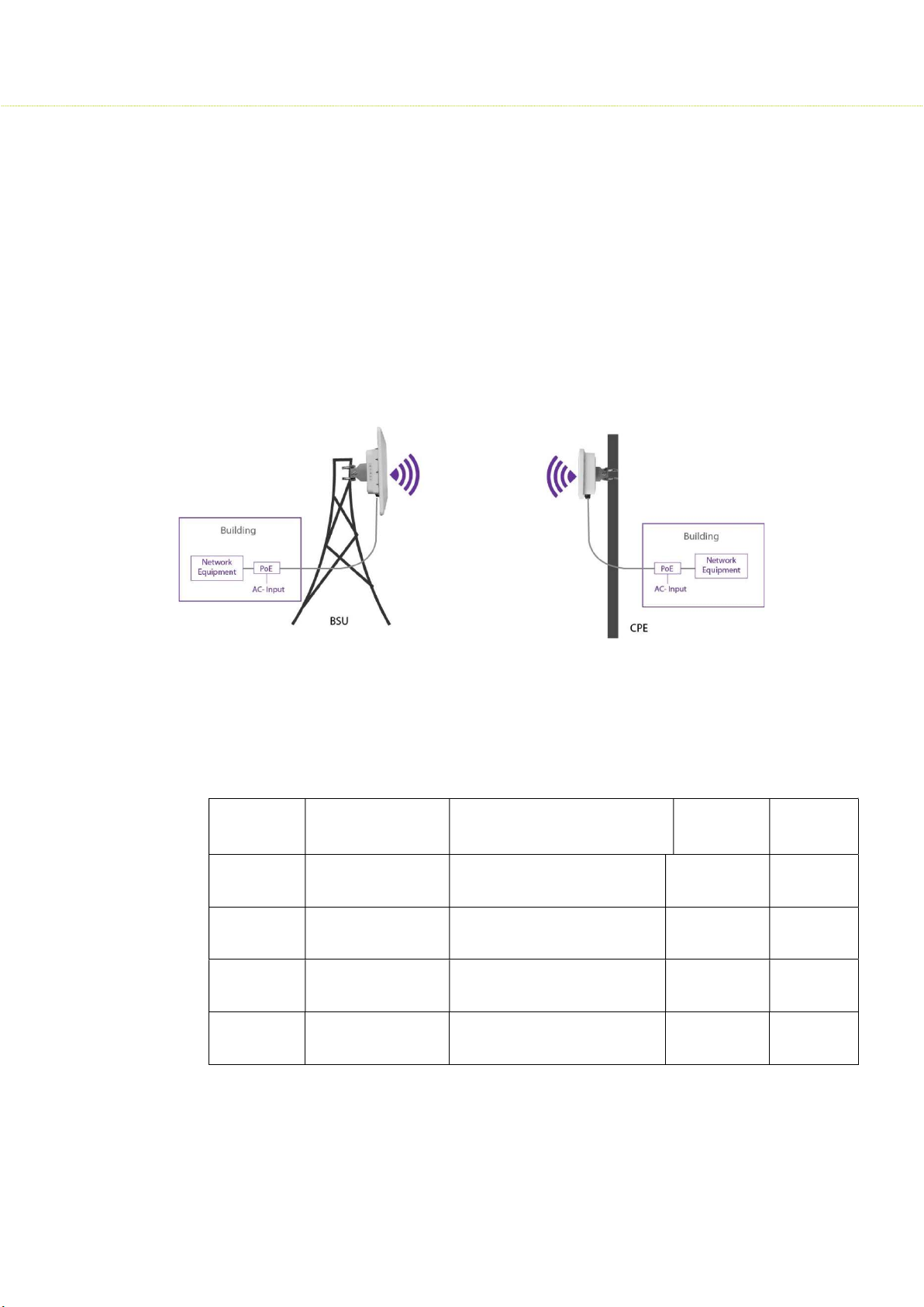
1.4 Typical Outdoor Installation of Radios
Sify SMAC3 Series products are all outdoor radios installed in one of the following
methods:
1. Pole/Tower Mount: Radio installation kit includes two metal hose clamps to
support pole sizes from 30mm to 60mm diameter.
2. Wall Mount: With optional wall mount kit, radios can be installed on the side of
the building or a structure without any obstruction to the radio antenna.
Please see below typical deployment.
1.5 Certified Antenna Gain & Tx Power Values
Antennas shown in the table below or antennas of the same type with lower gain are
approved for Sify Radio deployments.
Operating Frequency Band 5725 – 5850 MHz
Marketing
Model
API-18-5GAC2x2-W2
APX-EX-5GAC2x2-W2
SUI-23-5GAC2x2-W2
SUI-18-5GAC2x2-W2
Antenna P/N
MA-WC56-DP17 Integrated, dual Pol. Sector - 60° 18 14
MA-WO56-DP10
MA-WA56-DP23
MT-485053-CVH-
B_ICD_KW
External, dual pol. Omni - 11°
Integrated dual pol. Panel - 10°
Integrated dual pol. Panel - 17°
Antenna Type
Antenna
Gain (dBi)
10 22
23 23
18 23
Tx Power
Per Chain
(dBm)
8
Page 9
SMAC3 User Material
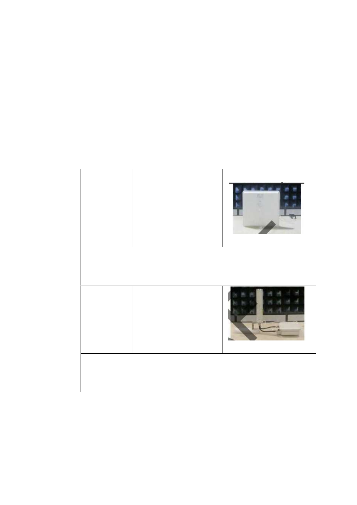
Due to device restrictions installation position is as above picture, thus consider above 30
Operating Frequency Band 5150 – 5250 MHz
It is the responsibility of the installer to ensure that radios operating in the band 5150-5250
MHz are installed so that they do not exceed 21 dBm EIRP at any elevation angle above 30
degrees as measured from the horizon, as specified in FCC rule 47 CFR Part 15.407 (a)(1)(i).
This compliance can be achieved through proper selection of radio with antenna, angle of
elevation, and Tx power control to provide reasonable protection for co-channel
NGSO/MSS operations.
As shown in the typical deployment above, the highest antenna gain from the horizon
above 30 degree for antenna model 1 & 2 is below. For more detail information, please
refer to antenna specifications.
Antenna No Antenna Gain Antenna Install Degree
1 0.77dBi
Due to device restrictions installation position is as above picture, thus consider above 30
degrees highest antenna gain is chosen from E-Plane antenna specification of 30-150
degrees, for H- plane antenna gain will not affect above 30 degrees from the horizon,
therefore not required for evaluation.
2 -4.88dBi
degrees highest antenna gain is chosen from E-Plane antenna specification of -60-60
degrees, for H-Plane antenna gain will not affect above 30 degrees from the horizon,
therefore not required for evaluation.
9
Page 10

The formula used for the calculation of the Transmit Power is given below:
Tx-Power = EIRP – Gant – Gmimo
EIRP Equivalent Isotropically Radiated Power
Gant Antenna Gain at 30° in Elevation plane
Gmimo Gain for Multi Input Multi Output (SMAC3 Series operate in 2x2 MIMO, in this
case the gain is 3 dB.)
Antennas shown in the table below or antennas of the same type with lower gain are
approved for deployments in frequency band 5150-5250 MHz with corresponding Transmit
Power per chain configuration in the SMAC3 Radios using above formula.
SMAC3 User Material
Marketing
Model
Antenna P/N Antenna Type Antenna
Gain
Tx Power Per
Chain (dBm)
(dBi)
API-18-5G-
AC2x2-W2
APX-EX-5G-
AC2x2-W2
SUI-23-5G-
AC2x2-W2
SUI-18-5G-
AC2x2-W2
MA-WC56-
DP17
MA-WO56-
DP10
MA-WA56-
DP23
MT-485053-
CVH-B_ICD_KW
Integrated, dual Pol.
Sector - 60°
External, dual pol.
Omni - 11°
Integrated dual pol.
Panel - 10°
Integrated dual pol.
Panel - 17°
18 10
10 19
23 10
18 10
10
Page 11

SMAC3 User Material
1.6 Safety Precautions
Safety Notices
1. Read, follow, and keep these instructions.
2. Heed all warnings.
3. Use attachments or accessories specified by the manufacturer only.
WARNING:
Do not use this product in a location that can be submerged by water.
Avoid using this product during an electrical storm. There may be a
remote risk of electric shock from lightning
Electrical Safety Information
• Compliance is required with respect to voltage, frequency, and current requirements
indicated on the manufacturer’s label. Connection to a different power source than those
specified may result in improper operation, damage to the equipment or pose a fire
hazard if the limitations are not followed.
• There are no operator serviceable parts inside this equipment. Service should be provided
only by a qualified service technician.
• This equipment is provided with a detachable power cord, which has an integral safety
ground wire intended for connection to a grounded safety outlet.
• Do not substitute the power cord with one that is not the provided approved type. Never
use an adapter plug to connect to a 2-wire outlet as this will defeat the continuity of the
grounding wire.
• The equipment requires the use of the ground wire as a part of the safety certification,
modification or misuse can provide a shock hazard that can result in serious injury or
death.
• Contact a qualified electrician or the manufacturer if there are questions about the
installation prior to connecting the equipment.
• Protective Earthling is provided by Listed AC adapter. Building installation shall provide
appropriate short-circuit backup protection.
• Protective bonding must be installed in accordance with local national wiring rules and
regulations.
11
Page 12

SMAC3 User Material
1.7 Product Overview
SMAC3 Series of products were tailored for Internet service providers (ISP’s) who wish to
deliver uninterrupted wireless connectivity to Enterprise campuses, Public Wi-Fi, Hospitality,
Educational institutions, Industrial campuses or just about any demanding outdoor
environment.
1.8 Product Key Features
• Supports IEEE802.11ac/a/b/g/n wireless standards with up to 867 Mbps Data rate
• Support Wave 2 MU-MIMO function on 5GHz radio
• Perform 256-QAM to enhance data rate
• Flexible RF planning with 20,40,80 MHz channel size
• Up to 23.5 dBm transmit power enabling long range connectivity
• Support Tx Beam forming to enlarge the transmitting distance
• Robust housing with IP67 enclosure rated to deploy at extreme weather
• Superior QoS with Application aware traffic shaping capability
• AES Encryption and Radius Authentication provides the most secure outdoor wireless
communication even in the unlicensed frequency spectrum
Thank you for using SMAC3 Series. It is a powerful, enhanced, enterprise scale product,
which functions as outdoor Access Point, Base Station Unit and Subscriber Units.
2 Device Configuration
2.1 Power On-Device
• Connect the PoE Injector to AC power socket using a power cord.
• Now connect PoE In to PC and PoE Out to the device.
12
Page 13
SMAC3 User Material
2.2 PC Configuration
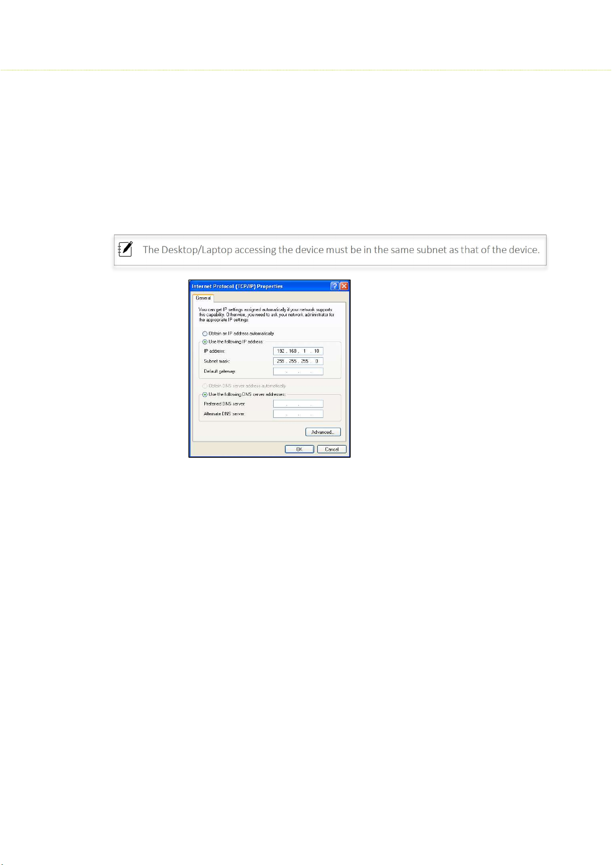
The Desktop/Laptop accessing the device must be in the same subnet as that of the device.
Local PC IP Configuration
• Connect the Ethernet LAN cable to the Desktop/Laptop.
• Go to Control Panel> Network and Internet settings> Set up a new connection
• Configure the Desktop/Laptop with a static IP address of 192.168.1.1 and a subnet mask of
255.255.255.0
2.3 Device Access Types
The Device can be accessed in the following ways:
Access through Ethernet
During initial setup, use a Wired Ethernet connection from the computer to the
device using a PoE.
Access through 2.4GHz Radio Interface
After the basic network configuration, scan for wireless devices that are available on
the network, default SSID is SMAC3_Wi-Fi with a passphrase as sify@1234
The device can also be accessed using Sify Network Mobile App or using any laptop
wireless connection.
13
Page 14
SMAC3 User Material
Access remotely over a network:
Once the wireless connection is established, the device can be accessed through a
link (PTP or PTMP) within the network.
2.4 Login Process
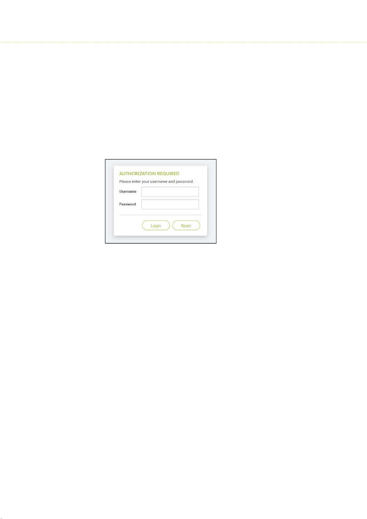
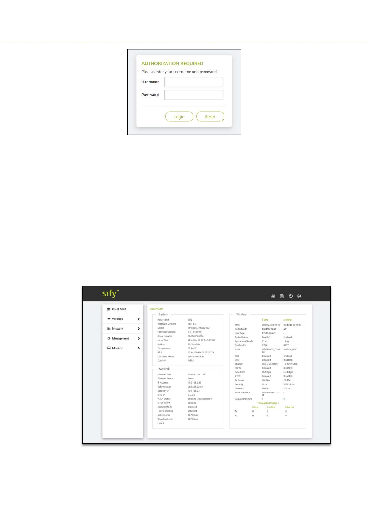
Launch any web browser on the PC that is connected to the device.
In the URL type 192.168.1.1 and enter the default credentials as user name: admin
and password: admin
Login and access the device settings
A Network administrator can use the following interfaces to configure, manage and
monitor the device:
HTTP / HTTPS
SNMP
Telnet
SSH
HTTP / HTTPS
The Web interface HTTP provides easy access to configure settings and network statistics
from any computer on the network. The Web interface can be accessed, through LAN,
the Internet, or with an Ethernet cable connected directly to the computer’s Ethernet
port.
HTTPS: Enabling HTTPS is to transfer and display web content securely
SNMP
The device can also be configured, managed and monitored by using Simple Network
Management Protocol (SNMP). SNMP is a networking management protocol used to
monitor network-attached devices, which will also collect errors and user statistics.
14
Page 15
SMAC3 User Material
Telnet
The device can be accessed through CLI by using Telnet, through LAN, or even with an
Ethernet cable connected directly to the computer’s Ethernet port.
To log on to the device using telnet:
Confirm that your computer has IP connectivity with the device
Use telnet client
Log on by entering username and password. The default login credentials are:
Username: admin; Password: admin
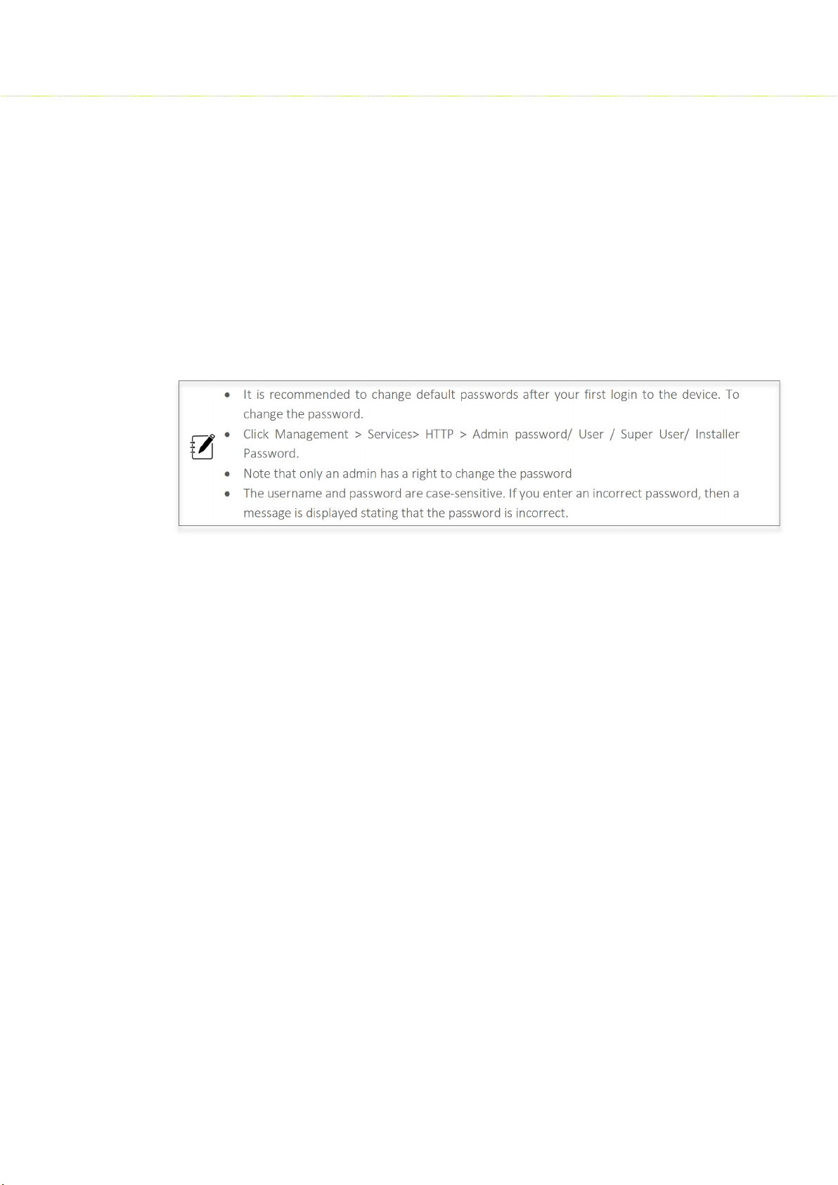
It is recommended to change default passwords after your first login to the device. To
change the password.
Click Management > Services> HTTP > Admin password/ User / Super User/ Installer
Password.
Note that only an admin has a right to change the password
The username and password are case-sensitive. If you enter an incorrect password, then a
message is displayed stating that the password is incorrect.
SSH
Enable Secure Shell (SSH) to make secure, encrypted connections in the network. Secure
Shell is a network protocol that allows data to be exchanged using a secure channel
between two network devices. The administrators are required to provide a username,
password, port number combination for authentication.
User Credentials and Roles
The network operator can configure, manage and monitor the device using
HTTP/SNMP/Telnet/SSH protocols. For this, a set of user credentials should be predefined for read-write permissions. Based on user roles the access should be granted.
There are four types of users: The admin, super user, user and the installer.
Admin
The Admin has full access to all the parameters in the settings of the device; this further
prevents unauthorized changes in settings.
15
Page 16

SMAC3 User Material
Super user
In case of accessing AP, the Super user has a read-only option, where he cannot create,
modify or delete any parameters.
In case of accessing SU, the Super user has read-only permission, but made few
custom- limited read-write permissions for parameters such as Ethernet Speed, VLAN
modes (Transparent and Access), Filtering, Traffic shaping, and Device Reboot.
User
While accessing AP and SU devices, the user has read-only permission, where he cannot
create, modify or delete any parameters.
Installer
The installer does not have full access to Access Point or Subscriber Unit, but he has readwrite permission for a few parameters such as IP configuration, Location parameters, and
Radio mode. The installer also can view site survey scan results (to join any AP) and observe
the link statistics status.
2.5 Quick Configuration
This section will show you how to do a quick configuration for both the outdoor Access Point
and Subscriber Units using a web-based configuration interface.
Please refer Devices Access Types or use your Ethernet port or wireless network to access
the AP/ SU and proceed.
After connecting via any one of the three-device access methods, the GUI will prompt you
to login with a password. The default username and password is "admin", and should be
changed immediately after login to protect your network since it gives the user read - write
privileges.
The password can be changed:
Click Management > Services> HTTP > Admin password/ User / Super User/ Installer
Password.
Web Configuration
Launch any web browser on the PC that is connected to the device.
In the URL type 192.168.1.1 and enter default credentials as user name: admin and
password: admin
Login and access the device settings in the GUI
16
Page 17
SMAC3 User Material
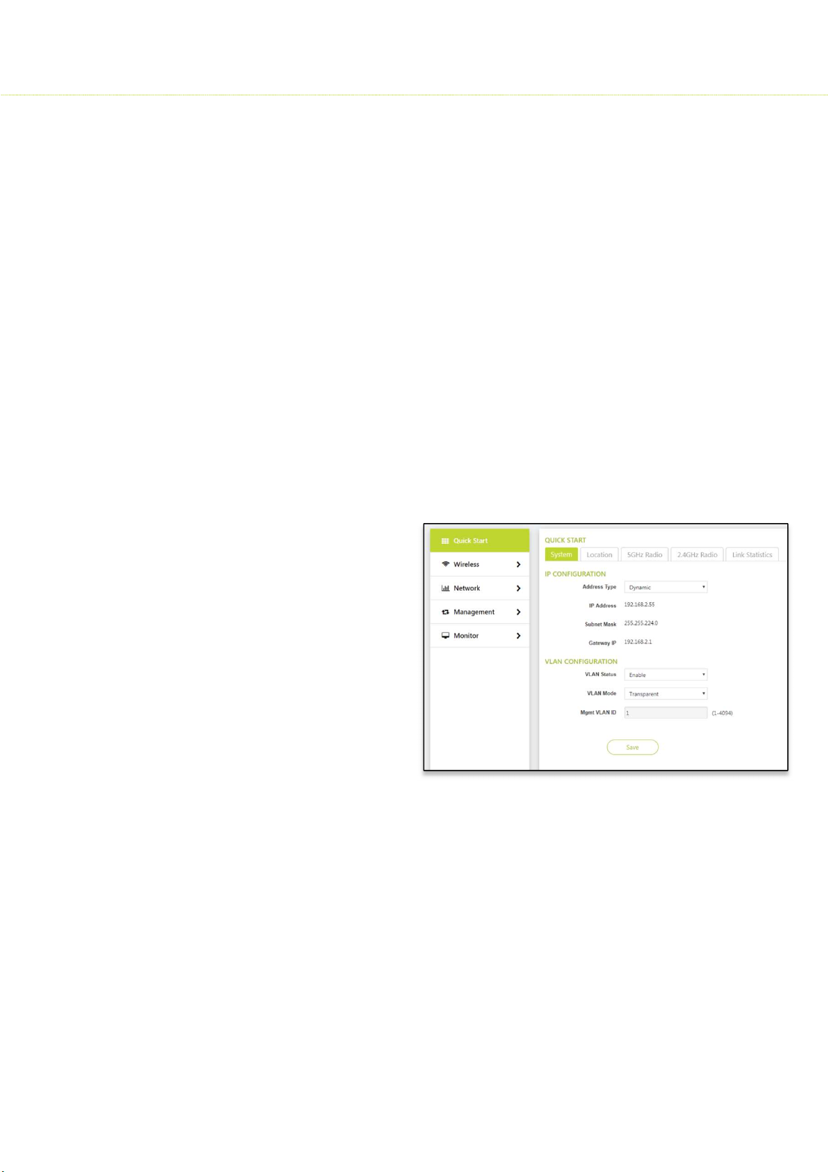
2.6 Graphical User Interface Overview
Power on the Radio to access the Graphical User Interface (GUI). After a successful login,
the user notices a title bar on the top, a navigation pane on the left, and a content pane in
the center. The default page shown in the content pane is the “Summary”.
Home: Click Home to return to the summary page, which displays all the key performance
parameters such as System, Network, Wireless, and Throughput.
Apply:
Reboot: Click Reboot for changes made in the configuration parameters to take effect. It
Logout: Click Logout when necessary, make sure to click Apply to save the most recent
Again, the login page is popped-out after a successful logout.
Click Apply to save all changes made to the configuration parameters
is mandatory to click Apply; before Reboot to take effect.
updates.
17
Page 18
3 Quick Start
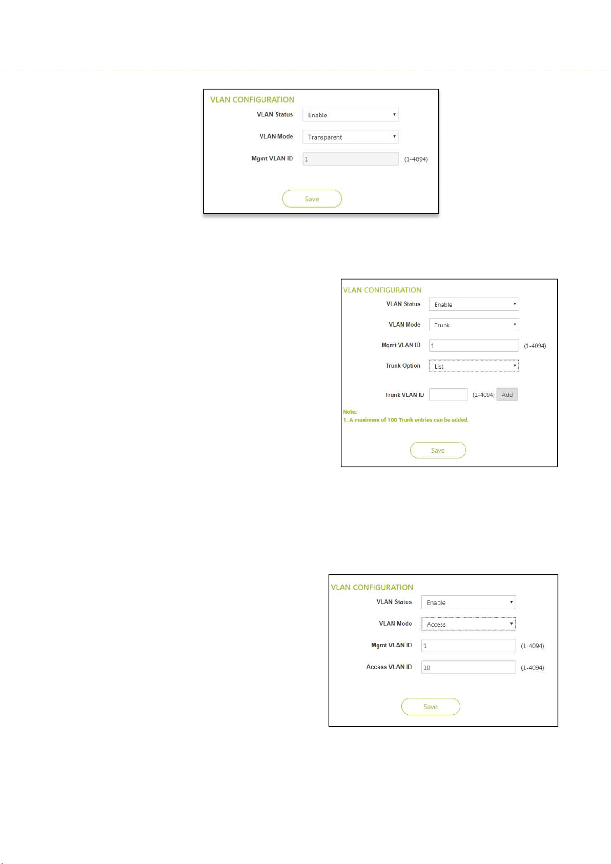
3.1 System
To configure the IP Configuration, Click Quick Start> System
Address Type: Dynamic / Static
IP Address: 192.168.1.1
Subnet Mask: 255.255.255.0
Gateway IP:
SMAC3 User Material
3.1.1 IP configuration
If Static is selected, the user should manually configure the network parameters.
If Dynamic is selected, the device obtains the IPv4 parameters from a DHCP server
automatically. According to the current software release, only IPv4 format is supported.
Represents the IP Address of the Ethernet interface
By default, the Static IP address is set to 192.168.1.1
When the Address Type is set to Dynamic, this parameter is read-only and displays the device
IP Address obtained from the DHCP server.
Subnet Mask Represents the subnet mask of the Ethernet interface.
By default, the subnet mask is 255.255.255.0.
When the address type is set to
Dynamic, this parameter is read-only
and displays the device current
subnet mask obtained from the
DHCP server.
The subnet mask will fall back to
255.255.255.0 if the device cannot
obtain the subnet mask from the
DHCP server.
Specifies the IP address of the
device gateway
When Address Type is set to
Dynamic, this parameter is read-only and displays the IP address of the device gateway. The
device will be set to the Default Gateway IP address 192.168.1.1 if it cannot obtain the
Gateway IP address from a DHCP server.
If the Address Type is set to Static then you have to enter manually the Gateway IP address.
18
Page 19

SMAC3 User Material
3.1.2 VLAN Configuration
Virtual Local Area Networks (VLANs) are logical groupings of network hosts. Defined by
software settings, other VLAN members or resources appear (to connected hosts) to be on
the same physical segment, no matter where they are attached on the logical LAN or WAN
segment. They simplify traffic flow between clients and their frequently used or restricted
resources.
A device can communicate across a VLAN-capable switch that analyses VLAN tagged frames
and directs traffic to the appropriate units. The purpose of this network is to provide an
easy way of modifying logical groups in the dynamic environment.
To configure the VLAN, Click Quick Start> System
VLAN Status: Enable/ Disable
VLAN Mode:
By default, VLAN Mode is Transparent in AP/SU
In case of SU, VLAN Mode can be any mode among the following:
Transparent / Trunk / Access / Q-in-Q
Management VLAN ID
This parameter is used to configure the Management VLAN ID. The management stations
must tag the management frames sent to the device with the management VLAN ID
specified in the device. The device will tag all the management frames from the device with
the specified management VLAN.
Before setting the Management VLAN ID from 1 to 4094, make sure that the
management platform or host is a member of the same VLAN; or else, your access
to the device will be lost.
If Tag Management is disabled, only untagged frames can access the device.
Transparent
To configure the VLAN Transparent Mode in AP or SU, Click Quick Start> System
Transparent Mode is available for the Ethernet and Wireless interfaces for both AP
and SU. It is equivalent to NO VLAN support and is the default mode.
An interface in transparent mode forwards both tagged and untagged frames.
The Management VLAN ID range can be between (1-4094)
19
Page 20
SMAC3 User Material
Trunk
To configure the VLAN Trunk Mode in SU,
Click Quick Start> System
Trunk mode is configurable only in
SU.
When an interface is in Trunk mode,
it forwards only those tagged frames
whose VLAN ID matches with a VLAN
ID present in trunk table. All other
frames will be dropped.
Access
To configure the VLAN Access Mode in SU, Click Quick Start> System
Access mode is available only on the Ethernet interface of SU.
In access mode, tagged frames with specified Access VLAN ID are going out of the
device through the Ethernet
interface were untagged and
forwarded.
The untagged frames coming into
the device through the Ethernet
interface are tagged with
specified Access VLAN ID and
forwarded.
20
Page 21
SMAC3 User Material
Q-in-Q
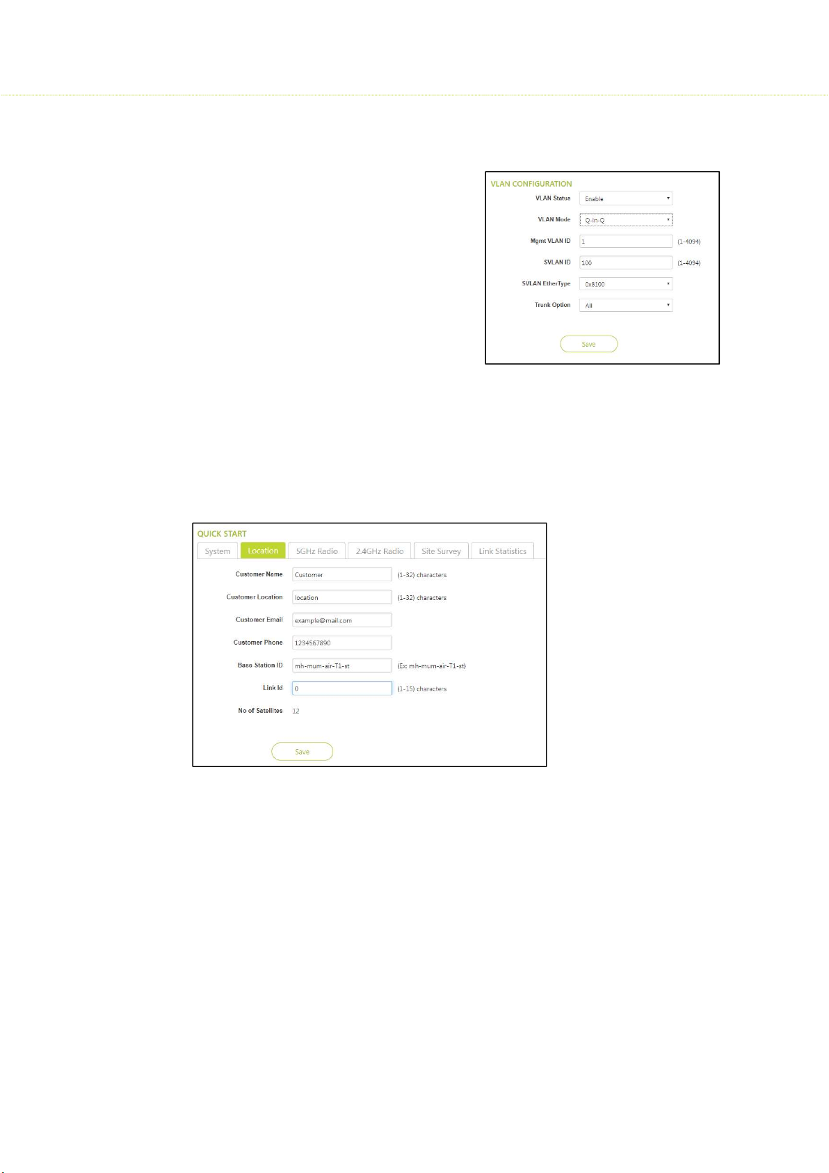
To configure the VLAN Q-in-Q in SU, Click Quick Start> System
This mode is well known for its double
tagging or stacking.
The Q-in-Q mechanism allows Service
Providers to maintain customer
assigned VLANs while avoiding
interference with the Service providers
VLANs.
Using the Q-in-Q mechanism, a SVLAN ID
is added to manage VLAN ID, such that
interference is avoided and traffic is
properly routed.
3.2 Location
To configure the Location, Click Quick Start> Location
This section consists of the basic profile information of customer’s device, such as Customer
name, Customer Location, Customer email, Customer Phone, Base Station ID and Link ID.
The major difference in AP
and SU location parameters
is that the SU have a Link Id
which is used to link to the
AP.
3.3 5 GHz Radio configuration
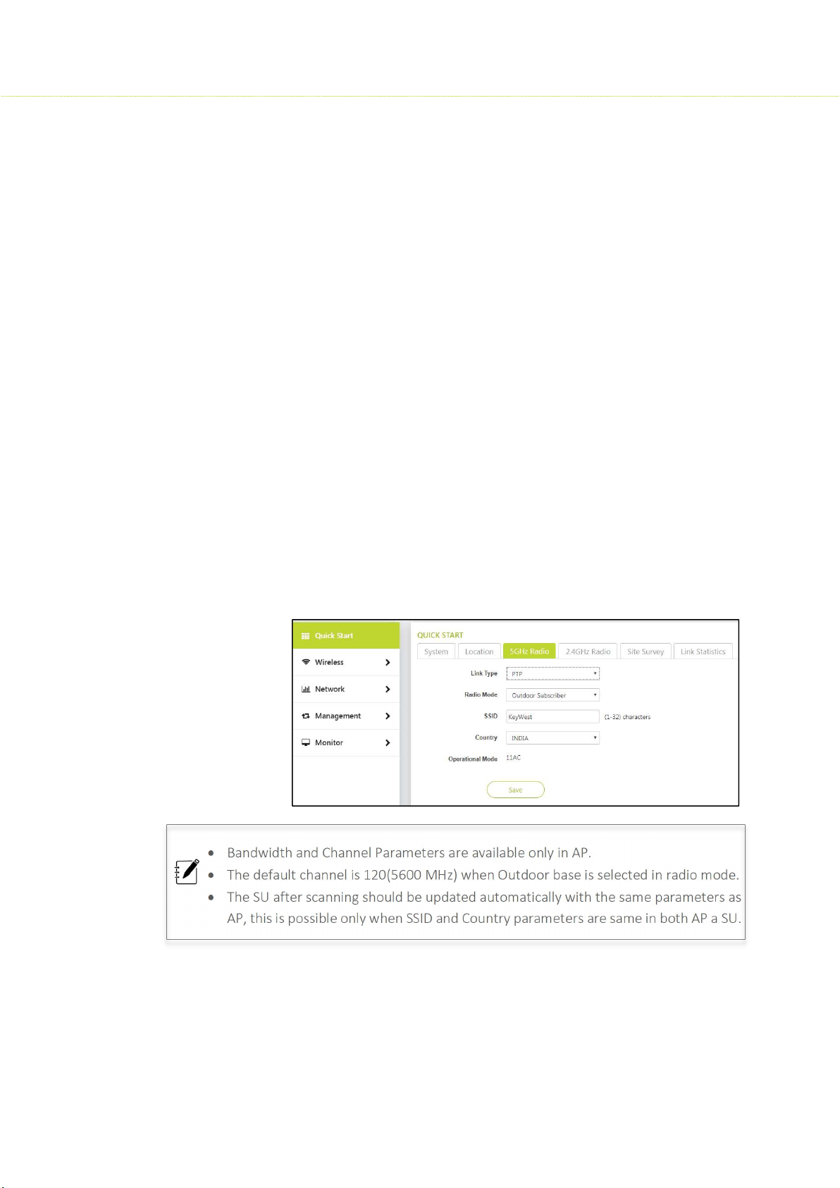
To configure the 5 GHz Radio configuration, Click Quick Start> 5 GHz Radio
Link Type
Link type is a mode of selecting a wireless connection between AP and SU radios. A Link
type here can be a PTP/ Backhaul/ PTMP. Few mandatory parameters are customized in AP
than in SU.
21
Page 22
SMAC3 User Material
Radio Mode
Outdoor Base / Outdoor Subscriber
If the Radio Mode is Outdoor Base, it is considered as AP.
If the Radio Mode is Outdoor Subscriber, is selected then it is a SU.
Service Set Identifier (SSID)
SSID is simply the technical term for a network name. The SSID is a case-sensitive text string
that can be as long as 32 characters consisting of letters and/or numbers. An SSID is publicly
visible. Within those rules, the SSID can be anything for quick identification of the network.
Country: India / 5 GHz
Band1 – 5100- 5350 MHz
Band2 – 5470- 5925 MHz
Operational Mode: 11AC
Bandwidth: 20/40/80MHz
Given the above options, the admin has the flexibility to select the bandwidth. In general,
2.4GHz radio can have a bandwidth of 20 MHz i.e. for short distances. A 5GHz radio can
have 40 MHz/ 80MHz bandwidth. Advantages of a 5 GHz with 40 MHz/ 80MHz bandwidth
are; it is tuned for faster speed; more data can be transferred and less signal interference.
Channel: Several Wi-Fi Channels and their numbers were pre-defined to achieve the best
performance.
Bandwidth and Channel Parameters are available only in AP.
The default channel is 120(5600 MHz) when Outdoor base is selected in radio mode.
The SU after scanning should be updated automatically with the same parameters as
AP, this is possible only when SSID and Country parameters are same in both AP a SU.
22
Page 23
SMAC3 User Material
3.4 2.4 GHZ Radio configuration
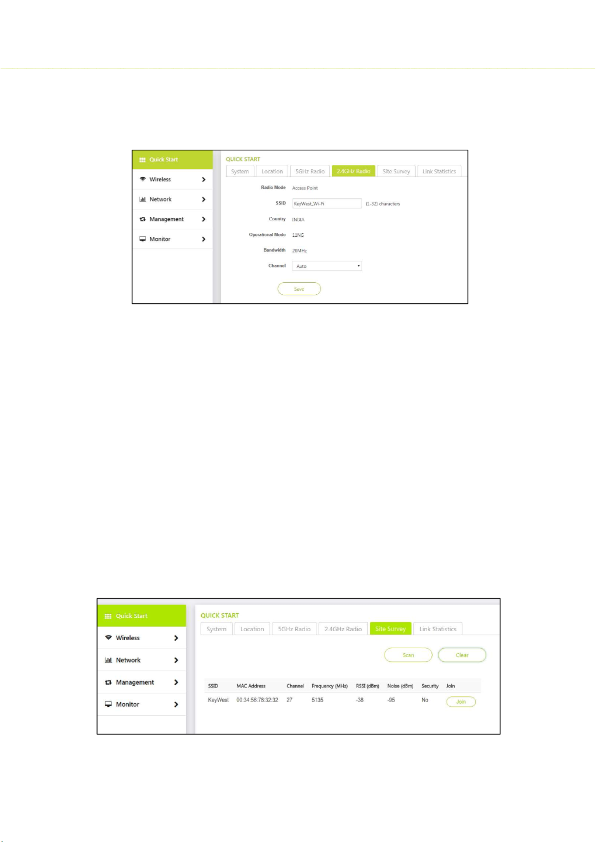
To configure the 2.4 GHz Radio configuration, Click Quick Start> 2.4 GHz Radio
Radio Mode: Access point
Service Set Identifier (SSID):
SSID is simply the technical term for a network name. The SSID is a case-sensitive text string
that can be as long as 32 characters consisting of letters and/or numbers. An SSID is publicly
visible. Within those rules, the SSID can be anything for quick identification of the network.
Country: India
Operational Mode: 11NG
Bandwidth: 20MHz
In general, 2.4GHz radio can have a bandwidth of 20 MHz i.e. for short distances.
Channel: Auto
When Auto is selected best, Wi-Fi Channel is selected to achieve the best performance.
3.5 Site Survey
To configure the Site Survey, Click Quick Start> 2.4 GHz Radio
Site Survey tab is custom-created for SU 5GHz Radio where it can scan and join the AP
with the same SSID.
23
Page 24
SMAC3 User Material
Once the Access Point parameters were configured, the subscriber unit will scan and get
parameters updated from the AP. This way SU’s basic configuration will be updated and
further need to be monitored.
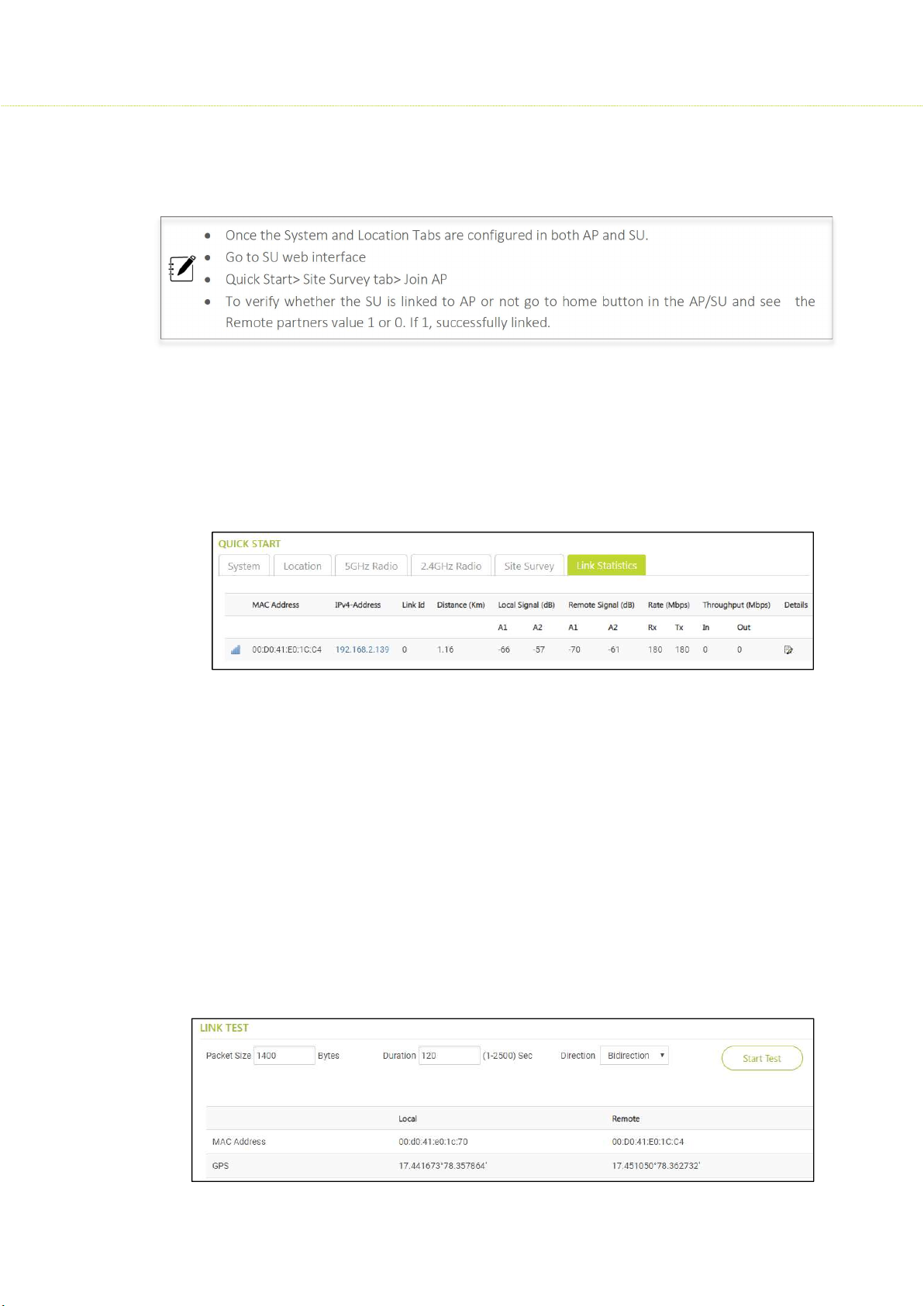
Once the System and Location Tabs are configured in both AP and SU.
Go to SU web interface
Quick Start> Site Survey tab> Join AP
To verify whether the SU is linked to AP or not go to home button in the AP/SU and see the
Remote partners value 1 or 0. If 1, successfully linked.
3.6 Link Statistics
To configure Link Statistics, Click Quick Start> Link Statistics
This is only for 5 GHz
Wireless PTP and PTMP link parameters are summarized in this tab. click the edit symbol
below the details. You will be directed to another window with detail statistics where you
can find a disconnect option and conduct a link test.
Link Test:
Link test in AP:
Navigate to Quick Start>Link Statistics> edit symbol
Here the Link test can be between AP to SU (or) SU to AP either downlink or bi -directional,
also input the packet size and duration before starting the test. The results of various
parameters are displayed in the same screen.
Link test in SU:
Navigate to Quick Start>Link Statistics> edit symbolHere the Link test can be between SU to
AP (or) AP to SU either uplink or bi -directional, also input the packet size and duration
before starting the test. The results of various parameters are displayed in the same
screen.
24
Page 25

4 Wireless
SMAC3 Series devices are Dual-Band radio’s that support (5GHz, 2.4GHz)
5GHz Radio Configuration
To configure 5GHz Radio Configuration, Click Wireless > 5 GHz Radio Configuration> Properties
4.1 Properties
Link Type
Link type is a mode of choosing a wireless connection between AP and SU radios. A Link type
here can be a PTP/ Backhaul/ PTMP
Radio Mode: Outdoor Base / Outdoor Subscriber
Service Set Identifier (SSID)
SSID is simply the technical term for a network name. The SSID is a case-sensitive text string that
can be as long as 32 characters consisting of letters and/or numbers. An SSID is publicly visible.
Within those rules, the SSID can be anything for quick identification of the network.
Country: India / 5 GHz Band 1: [5100- 5350 MHz]; Band 2[5470-5925 MHz]
SMAC3 User Material
If the Radio Mode is Outdoor Base, it is considered as AP.
If the Radio Mode is Outdoor Subscriber, is selected then it is a SU.
Operational Mode: 11AC
Bandwidth: 20/40/80MHz
Given the above options, the admin has the flexibility to select the bandwidth. In general, 2.4GHz
radio can have a bandwidth of 20 MHz i.e. for short distances. A 5GHz radio can have 40 MHz/
80MHz bandwidth. Advantages of a 5 GHz with 40 MHz/ 80MHz bandwidth are; it is tuned for faster
speed; more data can be transferred and less signal interference. This option is available only in
Access Point, but not in Subscriber Unit.
Channel
Several Wi-Fi Channels and their numbers are predefined to achieve the best performance. This is
available only in Access Point, but not in Subscriber Unit.
Distance
The distance between Access Point and Subscriber Unit should be mentioned in this section and
the distance can be (1-30) Km
Traffic Shaping
By default traffic shaping is disabled, the operator can create shaping policies if required to limit
traffic and then enable the traffic shaping and configure the uplink/downlink limit values.
25
Page 26
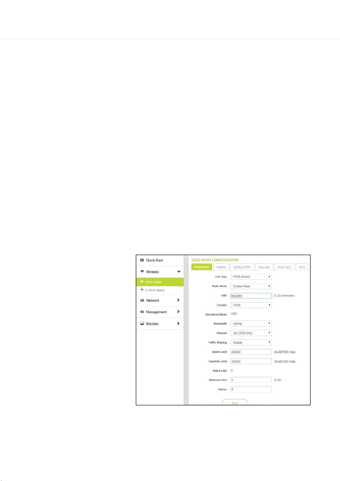
Uplink Limit
The administrator can set this limit only when traffic shaping in enabled, and the limit range is
(64-867000) Kbps that is from SU to AP.
Downlink Limit
The administrator can set this limit only when traffic shaping in enabled, and the limit range is
(64-867000) Kbps that is from AP to SU.
Hide ESSID
Extended Service Set Identifier (ESSID):
This should be unchecked when 5GHz radio (AP) is configured; which allows SU to identify the AP
with the configured network name.
Wireless Inactivity Timer
This parameter is configured only in SU, if there is no activity on wireless interface of SU in a
specified time interval, reset the wireless interface. The value should be configured in minutes.
An event log is generated when wireless inactivity triggers.
SMAC3 User Material
Link Inactivity Timer
If there is no activity on Wireless link on SU in a specified time, reset the wireless interface. An
event log is generated when link inactivity triggers. The value should be configured in minutes.
An event log is generated when Link inactivity triggers.
Max SUs
This range defines how
many SU’s are linked to AP.
The range can be (1-32).
Retries
This can be configured to
allow a packet to be
re-transmitted in specified
attempts.
26
Page 27
SMAC3 User Material
4.2 MIMO
To configure MIMO, Click Wireless> 5 GHz Radio Configuration > MIMO
SMAC3 Series devices support Multiple-Input-Multiple-Output (MIMO) antenna technology
that uses multiple antennas at both the transmitting end and receiving end to improve
communication performance.
The transmitting antenna uses multiple radio TX chains and signal paths to simultaneously
transmit different data streams, whereas the receiver combines the Rx signals resulting in
higher throughput.
By increasing the number of receiving and transmitting antennas, the throughput of the
channel increases linearly resulting in high spectral efficiency.
4.3 DDRS
Dynamic Data Rate Selection (DDRS) feature adjusts the transmission data rate to an optimal
value and provides the best possible throughput according to the current communication
conditions and link quality.
To configure DDRS, Click Wireless> 5 GHz Radio Configuration > DDRS
Select the Spatial stream as either as Auto, Single, or Dual.
Dual Stream: Select Dual for higher throughput.
Single Stream: Select Single for reliability and longer range.
Auto Stream: When you select Auto, DDRS decides the stream modes based on the
environmental conditions.
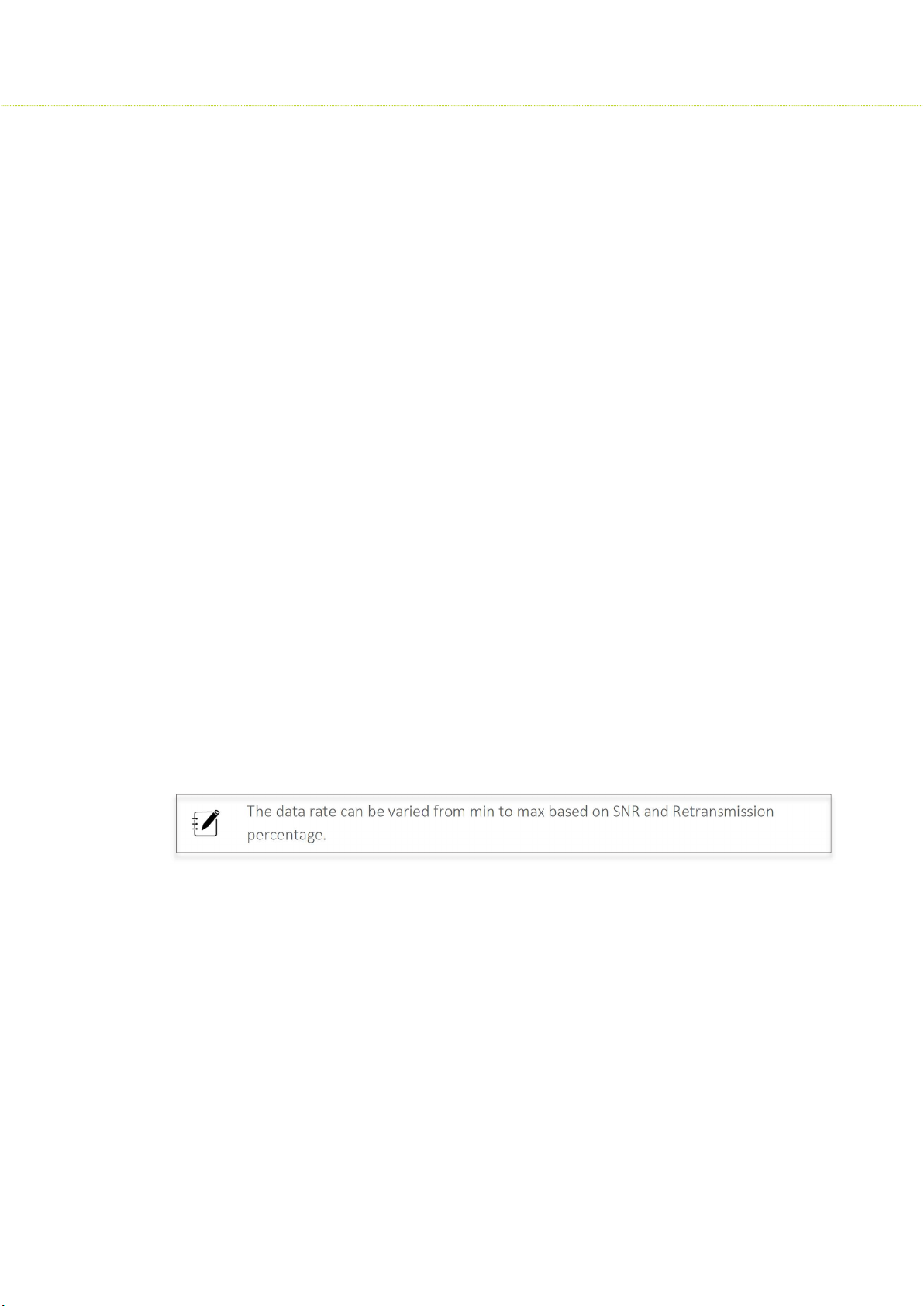
The data rate can be varied from min to max based on SNR and Retransmission
percentage.
ATPC
To configure ATPC, Click Wireless> 5 GHz Radio Configuration > ATPC
When you enable the Adaptive Transmit Power Control (ATPC), the device automatically
adjusts the transmit power to avoid saturation of remote receiver which could cause data
errors leading to lower throughput and link outage.
When you disable the ATPC, manually adjust the transmit power. The range should be
between (1-26) dbm
27
Page 28
SMAC3 User Material
4.4 Security
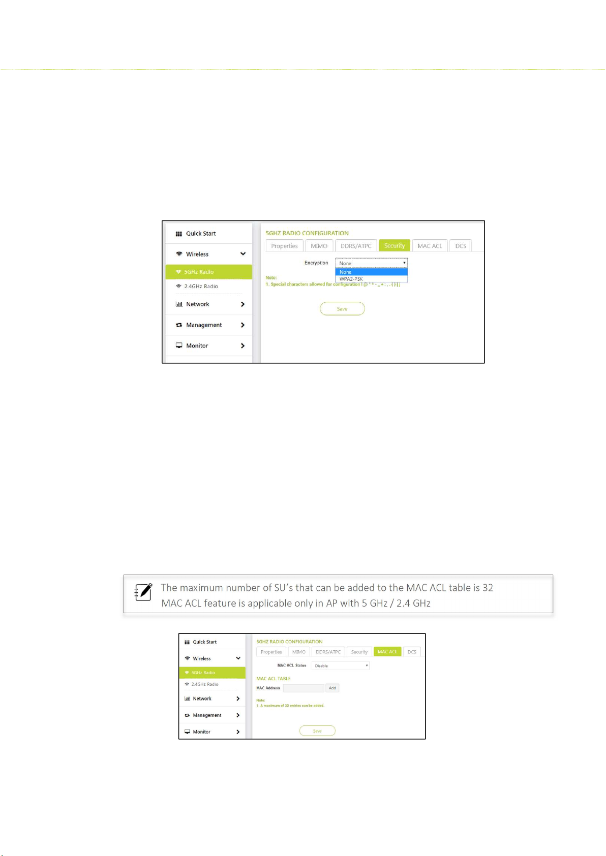
The Wireless Security feature helps to configure security mechanisms between AP and SU.
To configure Security, Click Wireless> 5 GHz Radio Configuration > Security
Encryption Type: Select WPA2-PSK
Key: Select any desired key considering the note below.
None: If the encryption type is selected as none, then there exists any security to the data
frames transmitted over the wireless medium
4.5 MAC-ACL
MAC Access Control List is an additional security mechanism in a wireless network.
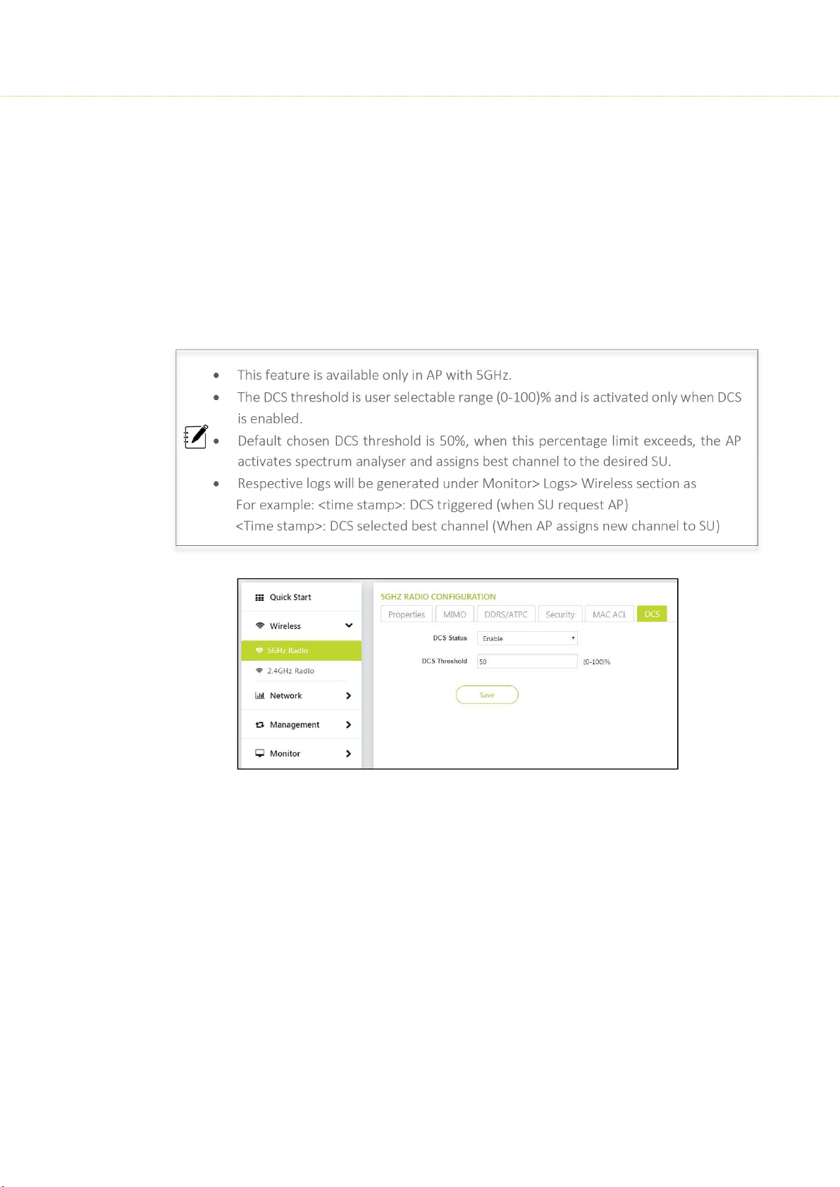
To configure MAC ACL in AP (5GHz), Click Wireless> 5 GHz Radio Configuration> MAC ACL
This section has MAC status: Allow/ Deny/Disable and a MAC ACL table: MAC Address
Disable: By, default MAC ACL is disabled in AP (5GHz) Configuration, i.e. all SU’s are linked to
AP
Allow: If Allow is selected, the MAC ACL feature allows only the authenticated SU’s to access
the wireless network of AP by adding their MAC addresses
Deny: If Deny is selected, only a particular SU is restricted.
The maximum number of SU’s that can be added to the MAC ACL table is 32
MAC ACL feature is applicable only in AP with 5 GHz / 2.4 GHz
28
Page 29
sss
SMAC3 User Material
4.6 DCS (Dynamic Channel Selection)
To enable DCS, Click Wireless> 5 GHz Radio> DCS
The DCS parameter allows an AP to monitor the retransmissions of packets transmitted to
the associated SU on the current operating channel.
When the average of Local RTX percentage of associated SU crosses user configured value,
before switching to new channel, AP evaluates local RTX percentage for 30 sec and triggers
Spectrum Analyser to scan the medium.
The Spectrum Analyser scans for less interference channel and associates the high priority
SU to the best channel available.
This feature is available only in AP with 5GHz.
The DCS threshold is user selectable range (0-100)% and is activated only when DCS
is enabled.
Default chosen DCS threshold is 50%, when this percentage limit exceeds, the AP
activates spectrum analyser and assigns best channel to the desired SU.
Respective logs will be generated under Monitor> Logs> Wireless section as
For example: <time stamp>: DCS triggered (when SU request AP)
<Time stamp>: DCS selected best channel (When AP assigns new channel to SU)
29
Page 30
SMAC3 User Material
2.4GHz Radio Configurations
4.7 Properties
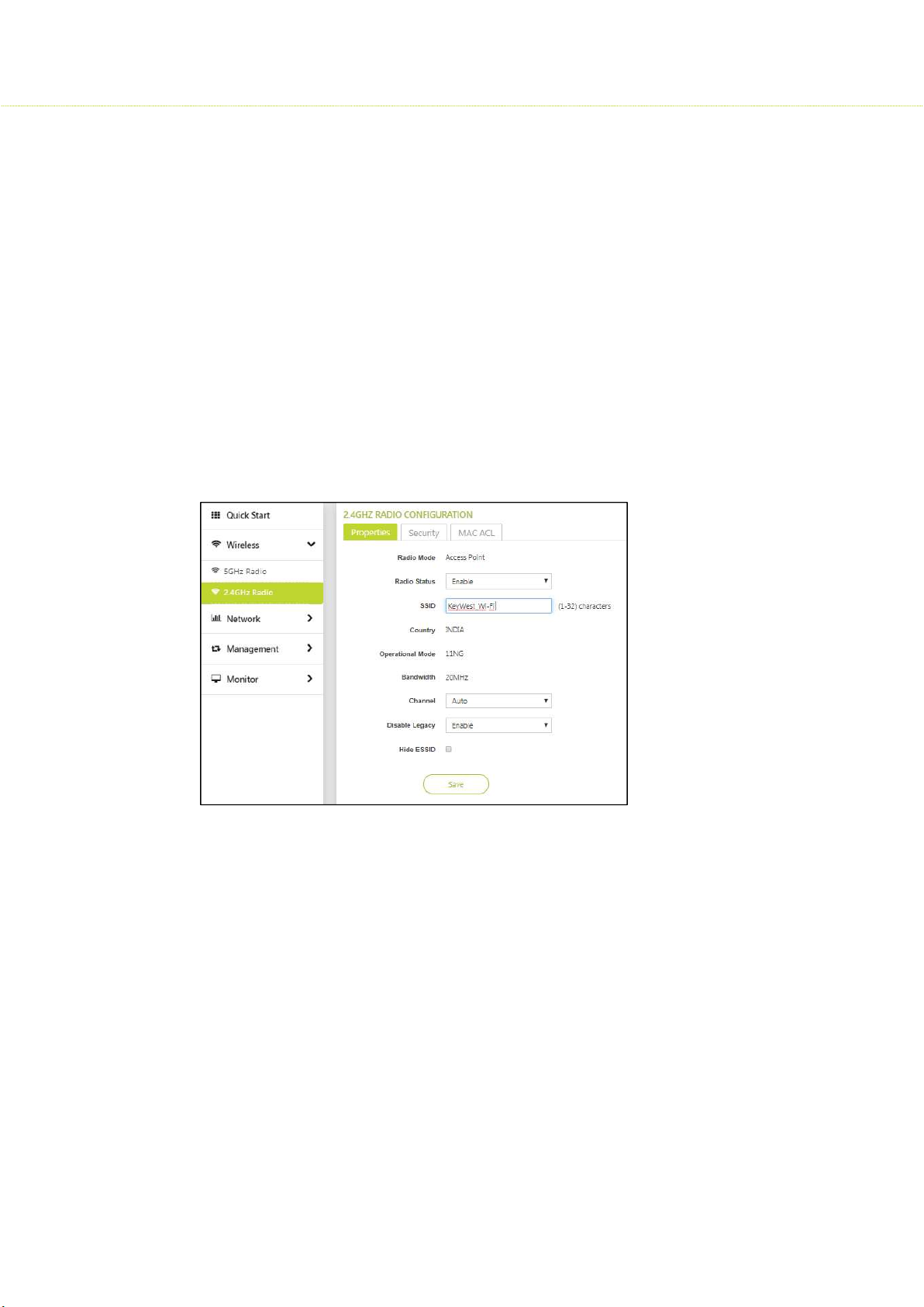
To configure properties, Click Wireless > 2.4 GHz Radio Configuration> Properties
Radio Mode: Access Point
Radio Status: Enable/ Disable
Service Set Identifier (SSID)
SSID is simply the technical term for a network name. The SSID is a case-sensitive
text string that can be as long as 32 characters consisting of letters and/or
numbers. An SSID is publicly visible. Within those rules, the SSID can be anything
for quick identification of the network.
Country: India Band1: [2402-2482 MHz]
Operational Mode: 11NG
Bandwidth: 20MHz
Channel: Several Wi-Fi Channels and their numbers are predefined to achieve the best
performance. This is available only in Access Point, but not in SU
Disable Legacy: Enable/ Disable
Hide ESSID:
Extended Service Set Identifier (ESSID):
This should be checked when 2.4GHz radio (SU) is configured, when checked ESSID is not
visible in the wireless network.
Max Clients: Maximum number of clients permissible to 2.4 GHz Radio can be between
(1-10).
30
Page 31
SMAC3 User Material
4.8 Security
The Wireless Security feature helps to configure security mechanisms between AP and SU.
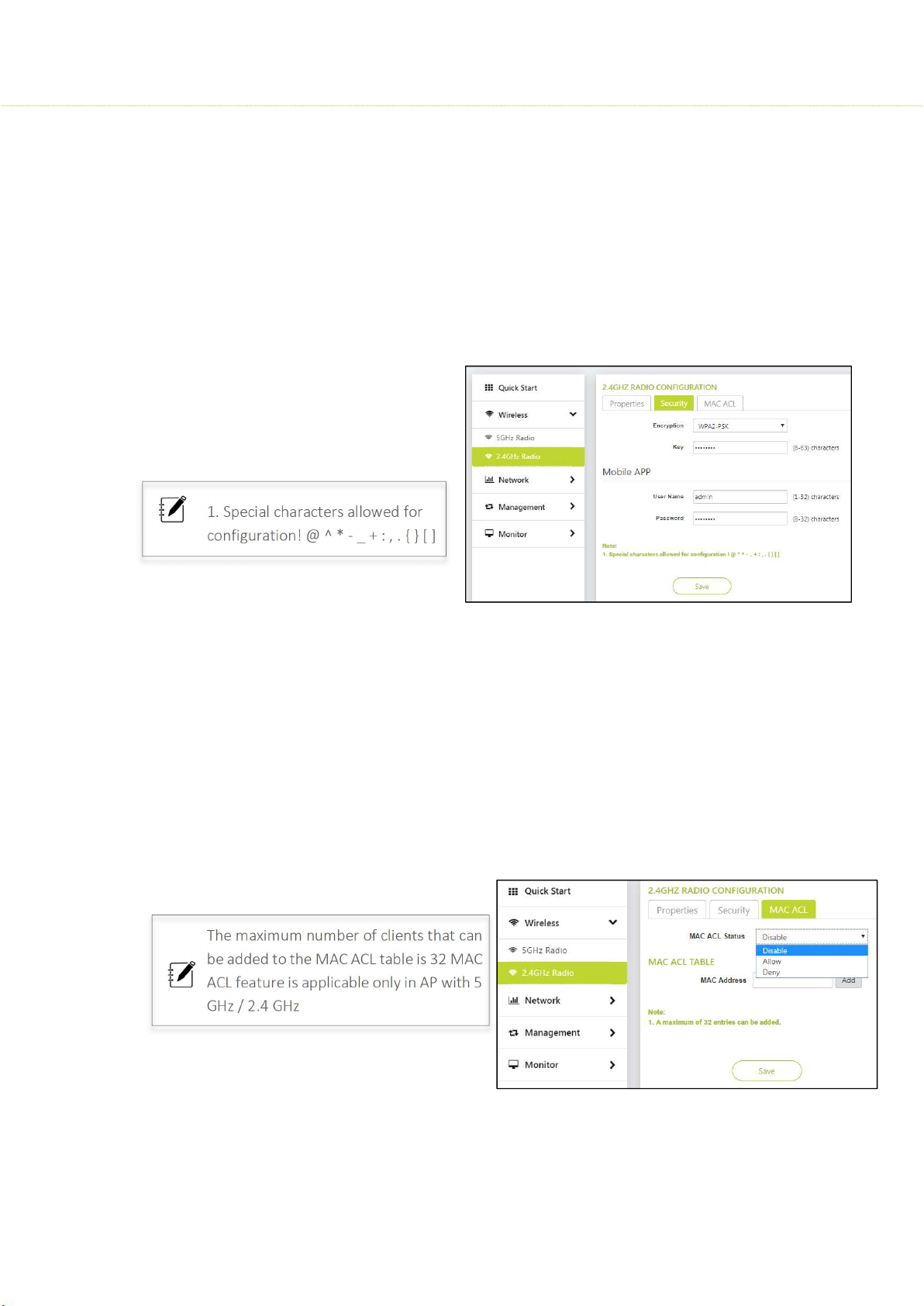
To configure Security, Click Wireless> 2.4 GHz Radio Configuration > Security
Encryption Type: Select WPA2-PSK
Key: Select any desired key considering the note below.
None: If the encryption type is selected as none, then there exists any security to the data
frames transmitted over the wireless medium
Mobile App: Mobile App is used to configure the Access point remotely
Username: admin (1-32) characters
Password: XXXXXXXX (8-32)
characters
1. Special characters allowed for
configuration! @ ^ * - _ + : , . { } [ ]
4.9 MAC-ACL
To configure MAC ACL in AP, click Wireless> 2.4 GHz Radio Configuration> MAC ACL
This section has MAC status: Allow/ Deny/Disable and a MAC ACL table: MAC Address
Disable: By, default MAC ACL is disabled in AP (2.4 GHz) Configuration, i.e. all clients are
linked to AP
Allow: If Allow is selected, the MAC ACL feature allows only the authenticated clients to
access the wireless network of AP by adding their MAC addresses
Deny: If Deny is selected, only a particular
client is restricted.
The maximum number of clients that can
be added to the MAC ACL table is 32 MAC
ACL feature is applicable only in AP with 5
GHz / 2.4 GHz
31
Page 32
5 Network
5.1 IP Configuration in AP/SU
SMAC3 User Material
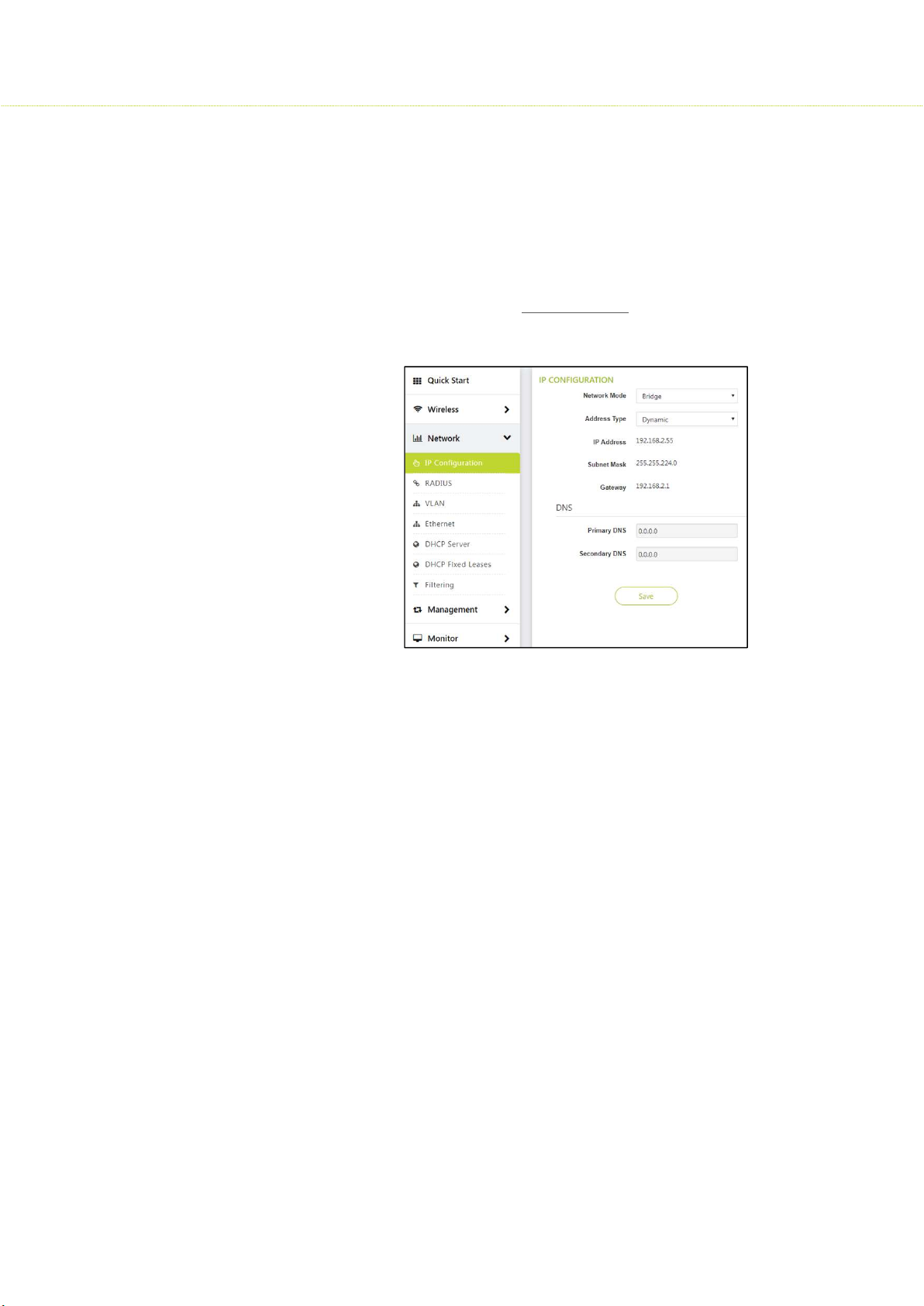
To configure the IP Configuration, Click Network > IP Configuration
Network mode: Bridge
For Detailed IP Configuration explanation, click IP Configuration
DNS
A domain name server is an Internet service that translates domain names into IP
addresses.
Primary DNS and Secondary DNS
In most cases, a primary and a secondary DNS server are configured on a PC that is
connected to an internet service provider (ISP). There are two DNS servers in case one of
them happens to fail, in which case the second is used to resolve hostnames you enter.
• Note: If the DNS server could not find the correct IP address that's associated with
the host name you enter, the website can't be located and loaded
• While configuring IP in SU few other parameters are to be considered such as:
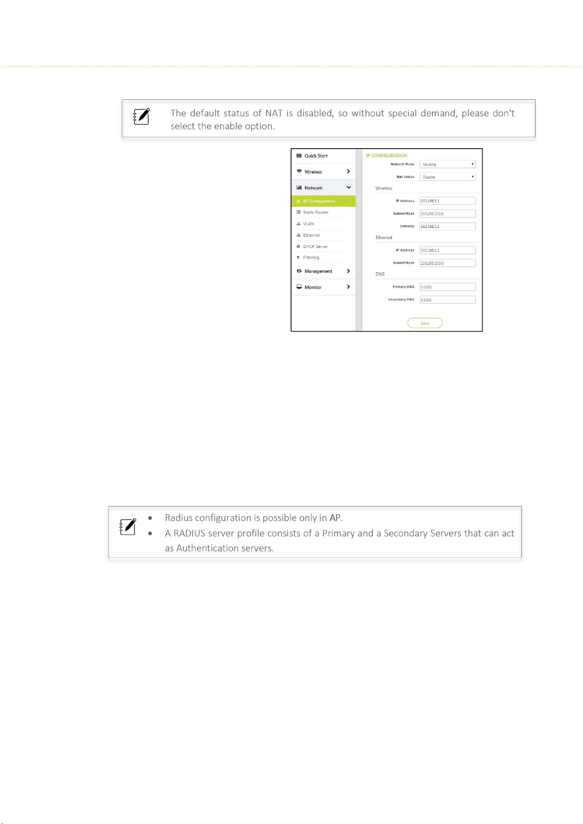
Network mode: Routing
Nat Status: Enable/Disable
If NAT is turned off, the device will work on pure-router mode.
32
Page 33
SMAC3 User Material
The default status of NAT is disabled, so without special demand, please don't
select the enable option.
Wireless
IP Address: 192.168.1.1
Subnet Mask: 255.255.255.0
Gateway IP: 192.168.3.1
Ethernet
IP Address: 192.168.2.55
Subnet Mask: 255.255.255.0
5.2 Radius
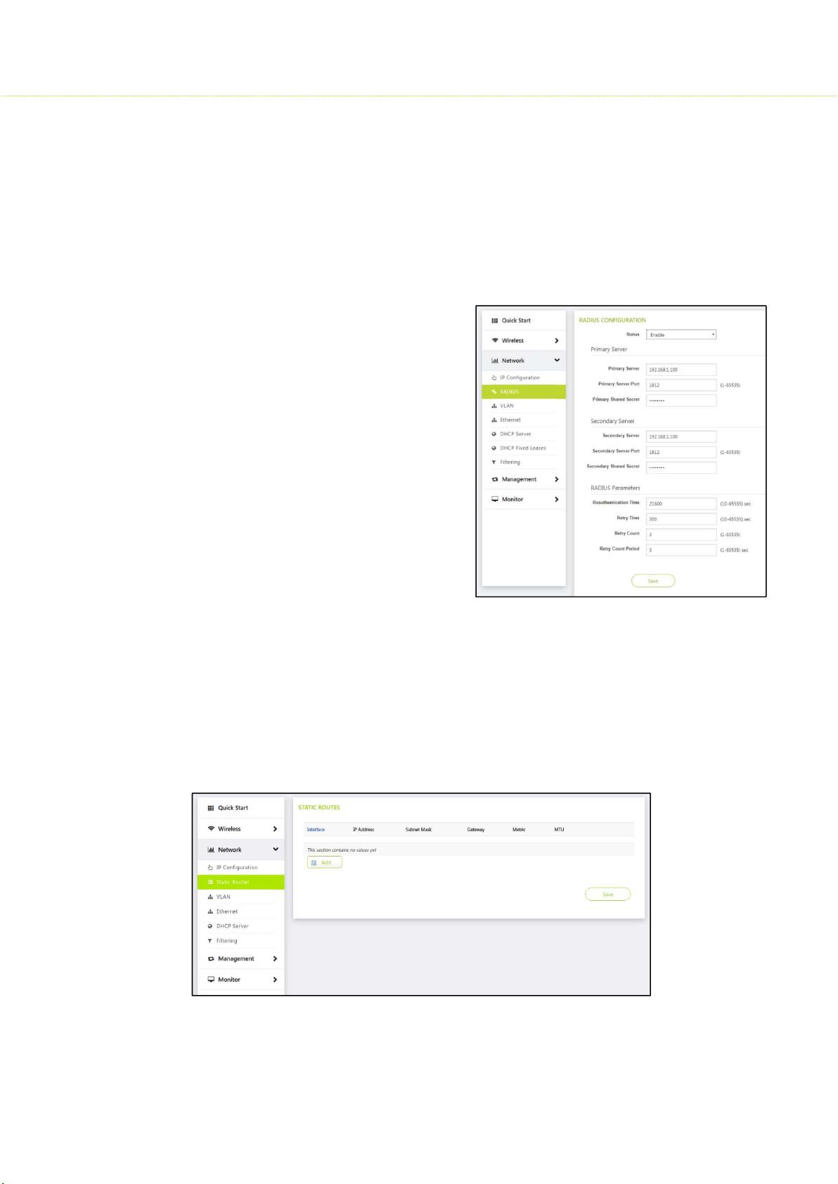
To configure RADIUS, Click Network > RADIUS > RADIUS Configuration
The RADIUS server is a background process that serves the following functions:
Remote Authentication Dial In User Service (RADIUS) is a client/server networking
protocol.
It provides centralized Authentication, Authorization, and Accounting (AAA)
management for computers to connect and use a network service
To authenticate users or devices before granting them access to a network
Radius configuration is possible only in AP.
A RADIUS server profile consists of a Primary and a Secondary Servers that can act
as Authentication servers.
Configure Primary and Secondary parameters
Primary Server: IP address of RADIUS server
Primary Server Port: The port number on which the RADIUS server is operating
Primary shared secret: An Authentication is required to connect the RADIUS Server to Client
If Primary Server fails, then secondary parameter configuration is used. Configuration of
Secondary Authentication Server is optional.
33
Page 34
SMAC3 User Material
Radius Parameters
Reauthentication Time: Represents the maximum number of times an authentication
request may be retransmitted to the configured RADIUS server. The time range can be
between (10-65535) sec
Retry Time: Represents the response time for which the AP should wait for the RADIUS
server to respond to a request. The retry time range can be between (10-65535) sec
Retry count: When a client tries to establish a
connection to a RADIUS server, the number
of retry counts is mentioned here. The retry
count period can be between (1-65535) sec
Retry count period: Represents the time after
which the RADIUS server should reauthenticate a SU. The retry count period
can be between (1-65535) sec
5.3 Static Routes
Note: This is available only in SU
To configure Static Routes, Click Network > Static Routes
Static Routing is manually configured by a network administrator. Static routes are
normally implemented in those situations where the choices in route selections are
limited, or there is only a single default route available.
34
Page 35
SMAC3 User Material
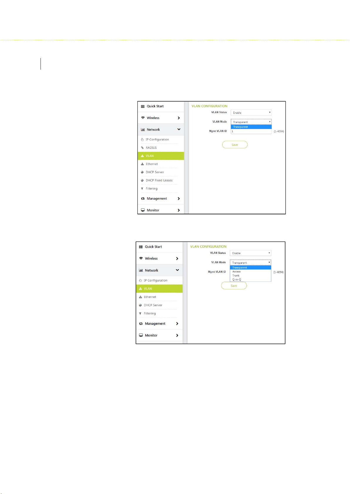
5.4 VLAN
To configure VLAN, Click Network>VLAN> VLAN Configuration
For Detailed explanation, click VLAN
VLAN in AP
VLAN in SU
35
Page 36
SMAC3 User Material
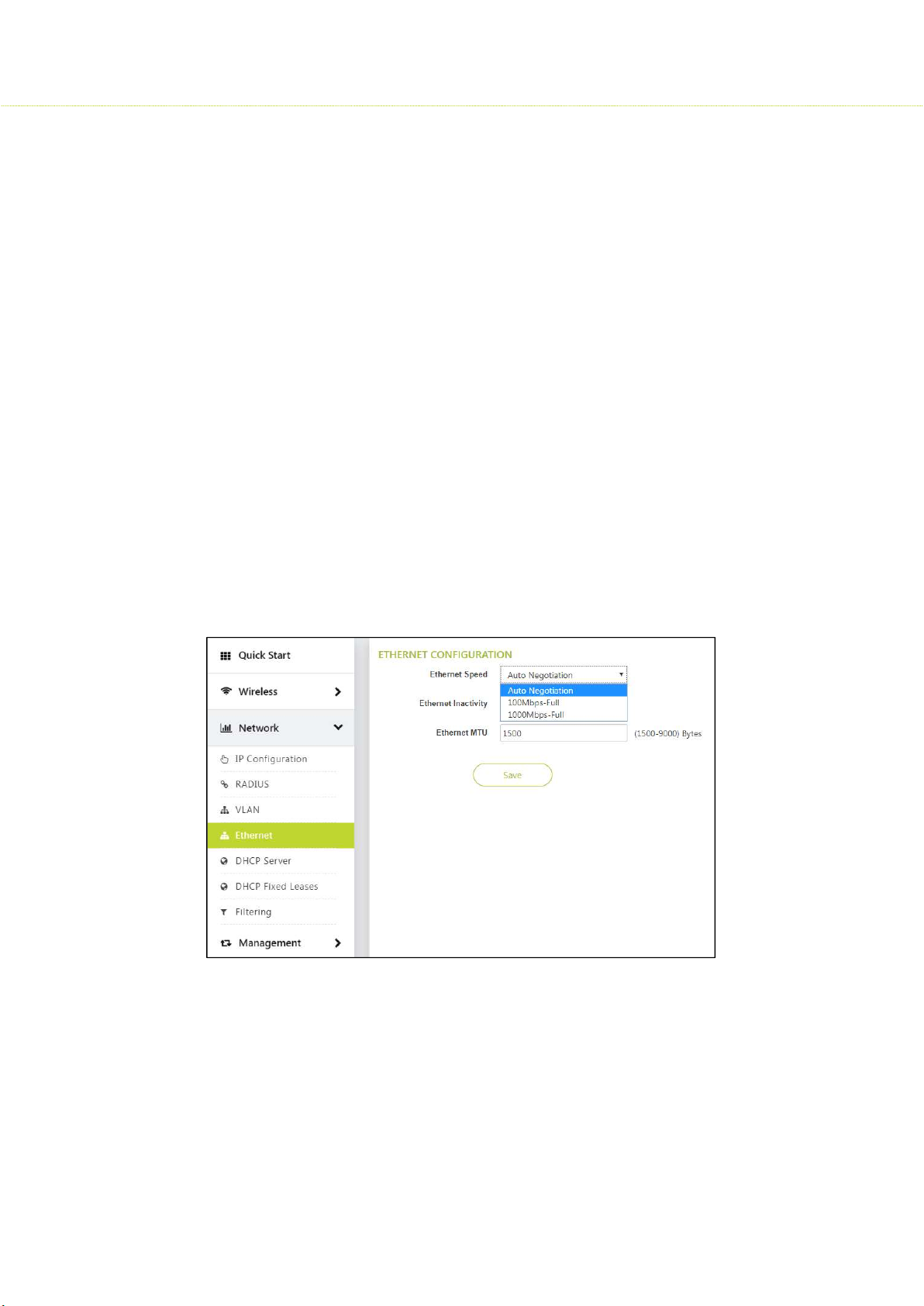
5.5 Ethernet
To configure Ethernet, Click Networks> Ethernet > Ethernet Configuration
Ethernet Speed
Auto Negotiation
When this option is chosen in AP/SU, the Ethernet configuration tries to auto negotiate.
Based on connected switch/router to send the optimal mode for speed connection.
100 Mbps- Full and 1000 Mbps–Full
Allows two-way transmission simultaneously
Displays whether 100 Mbps- Full or 1000 Mbps–Full Ethernet transmission mode
Ethernet Inactivity
By default, it is disabled where no activity takes place.
If Enabled and no activity is happening for 5 min, it will reset the Ethernet interface
automatically and a log is generated.
Ethernet MTU
This parameter determines the limit of transmission allowed for a data packet sent or
received on the wireless interface. The MTU size varies from 1500 to 9000 bytes.
36
Page 37
SMAC3 User Material
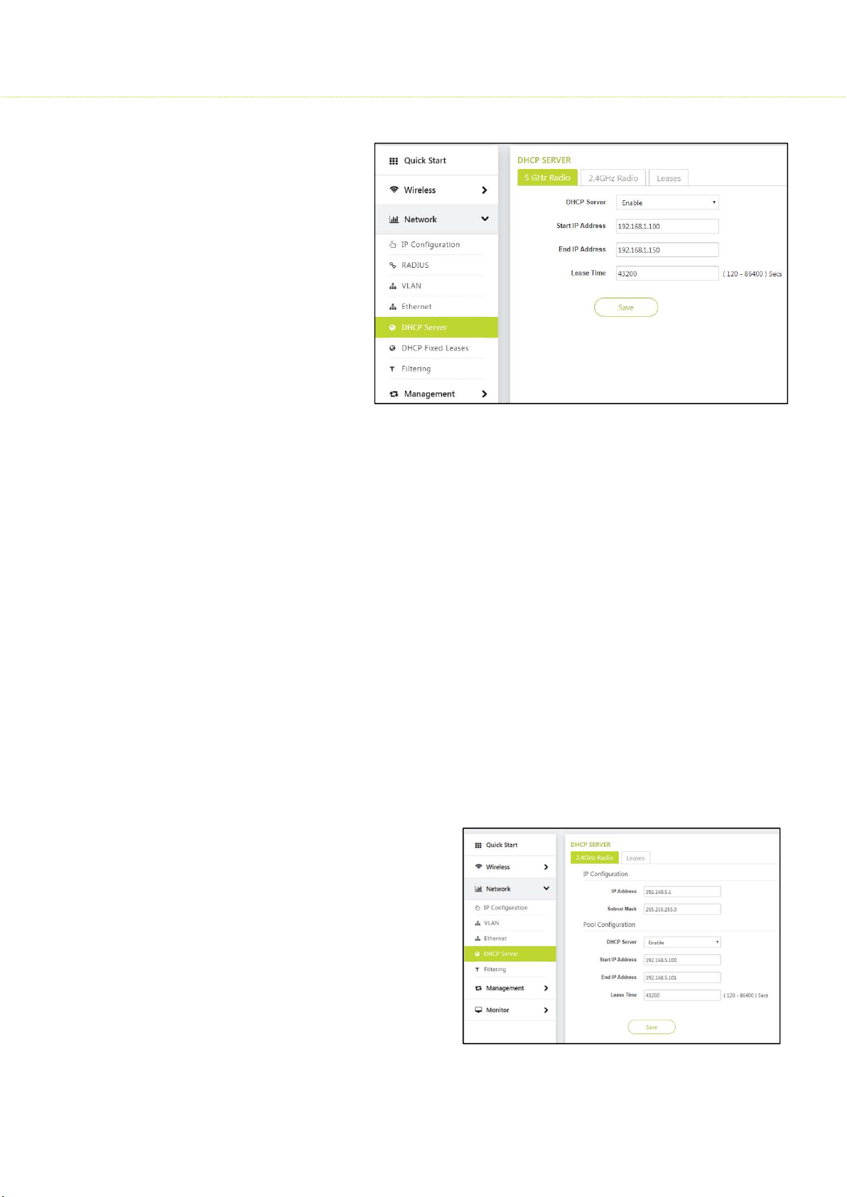
5.6 DHCP Server
Dynamic Host Configuration
Protocol (DHCP) is a
network protocol that
enables a server to assign an
IP address to the DHCP
client from a defined range
of IP addresses configured
for a given network.
Allocating IP addresses from
a central location simplifies
the process of configuring IP
addresses to individual
DHCP clients, and also
avoids IP conflicts.
If DHCP Server is enabled, it picks automatically the IP addresses from the specific interface
address and assigns them to the respective DHCP clients.
5.6.1 5 GHz Radio
To configure the DHCP server parameters, Click Network > DHCP Server > 5 GHz
Radio
DHCP Server Status by default disabled, when enabled one should enter the Start IP
Address and End IP Address so that it will save the IP Addresses in the given range.
5.6.2 2.4 GHz Radio
To configure the DHCP server parameters, Click Network > DHCP Server> 2.4 GHz
Radio A DHCP server is configured with a pool of available IP addresses and assigns
one of them to the DHCP client.
Lease time: Specifies the
maximum lease time for which
the DHCP client can use the IP
address provided by the DHCP
Server. The value ranges
from 120 - 86400 seconds.
37
Page 38
SMAC3 User Material
5.7 DHCP fixed Leases
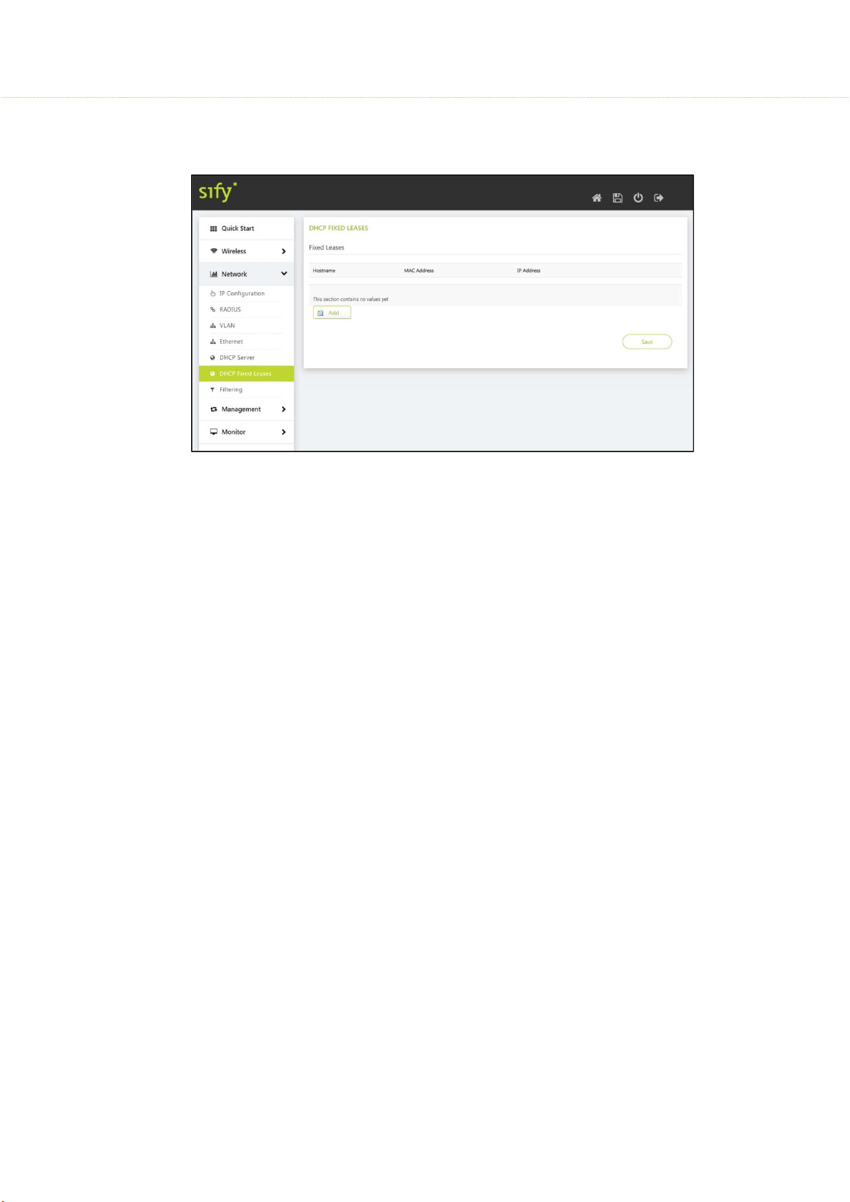
Here the MAC address and IP address are binded and listed down
5.8 Filtering
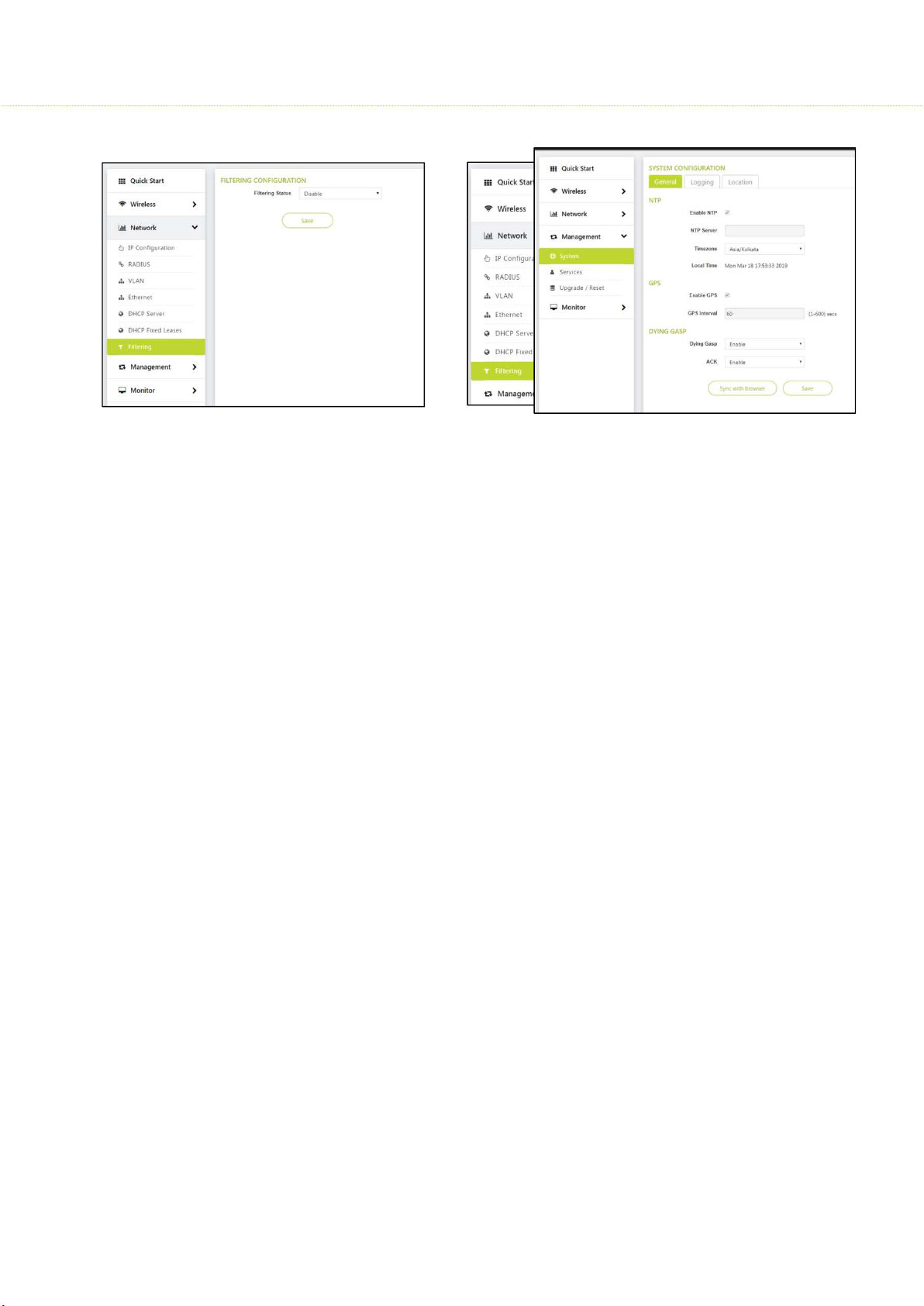
Filtering is useful in controlling the amount of traffic exchanged between the wired and
wireless networks. By using filtering methods, we can restrict any unauthorized packets from
accessing the network. This is used to drop broadcast and multicast packets. Hence filtering
can increase the amount of bandwidth available on the network and increase the network
security.
Filtering is available in bridge mode and routing mode.
Filters are activated only when they are globally enabled on the device.
To Configure Filtering, Click Network > Filtering > Filtering Configuration
Filtering Status: Default status is enabled
If Layer 2 Multicast is enabled, entire Layer 2 multicast (MAC layer) traffic will be
dropped.
If Layer 2 Broadcast is enabled, entire Layer 2 Broadcast (IP layer) traffic will be
dropped.
If Layer 3 Multicast is enabled, entire Layer 3 multicast (MAC layer) traffic will be
dropped.
If Layer 3 Broadcast is enabled, entire Layer 3 Broadcast (IP layer) traffic will be
dropped.
38
Page 39
SMAC3 User Material
6
Management
This chapter provides information on how to manage the device by using Web interface. It contains
information on the following:
6.1 System Configuration
To configure General, Click Management > System > System Configuration> General
6.1.1 General
NTP
This option allows user to enable or disable NTP feature. If enabled, user has to
configure the NTP server. The device will synchronize its local time with NTP server.
GPS
This option allows user to enable and disable the GPS feature. GPS feature
will trigger the 1PPS pulses to retrieve the GPS information like latitude,
longitude, number of satellites and local time.
The device will configure its local time if NTP is not enabled.
The GPS information is also used for calculating the distance between AP
and SU.
Dying Gasp
This option allows user to enable or disable the Dying gasp feature. Dying Gasp
feature will trigger a TRAP in the event of power failure to inform the remote device
that it is shutting down due to power failure. The device can hold its power
maximum for 20ms to allow the TRAP to be sent out in either wireless or wired
interfaces.
39
Page 40
SMAC3 User Material
ACK
When Dying Gasp is enabled in AP and a power failure happens in a SU. The SU
informs the wireless AP.
Once the AP receives Dying Gasp packet form SU, the AP sends acknowledgement
to SU. When the SU receive acknowledgement (ACK) from AP, it will stop sending
Dying Gasp packets to AP.
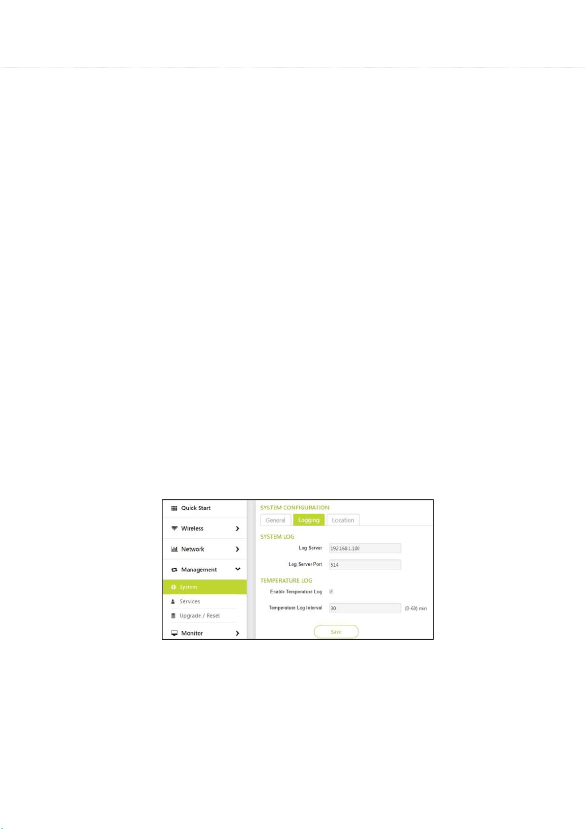
6.2 Logging
To configure logging, Click Management > System > System Configuration> logging
System log
System logs can be stored in external syslog server on PC
Log Server IP
Configure the PC IP Address on which syslog server is running
Log Server Port: The port on which the current log server is operating
Temperature log
Temperature Log feature is used to log the internal temperature of the device for the
configured temperature logging interval (By default, it is 30 minutes). For every 30 min, new
log is generated with temperature in °C.
To access this feature, navigate to Management >System> logging > Temperature and
configure the following parameters:
Enable Temperature Log
Temperature log interval (0- 60) minutes
40
Page 41
SMAC3 User Material
6.3 Location
To configure location, Click Management > System > System Configuration> location
This section consists of the basic profile information of customer’s device, such as Customer
name, Customer Location, Customer email, Customer Phone, Base Station ID and Link ID.
The major difference in AP and SU location parameters is that the SU have a Link Id which is
used to link to the AP.
6.4 Services
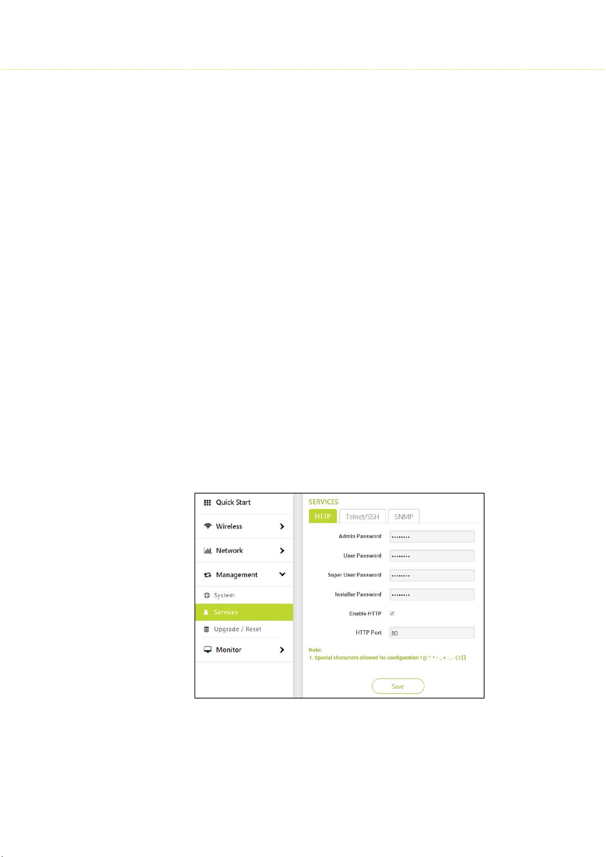
The device can be managed using different management protocols. The supported protocols
are HTTP, Telnet/SSH, SNMP.
To configure the Services, Click Management > Services
6.4.1 HTTP: Passwords setting or modification can be done in this section. Only Admin
has a privilege to change the passwords.
6.4.2 Telnet/ SSH: Enable Telnet/SSH and specify number of sessions. Here default is 2
sessions
6.4.3 SNMP: Enable SNMP
SNMP version: SNMP v1, SNMPv1-v2
SNMP Read Password: Here only Read password is available in order to read the
configuration from the SNMP.
SNMP Trap Host IP Address: Here the IP address of a Trap Server is specified
SNMP Trap Host Password: The password is set to secure the Trap sent.
41
Page 42
SMAC3 User Material
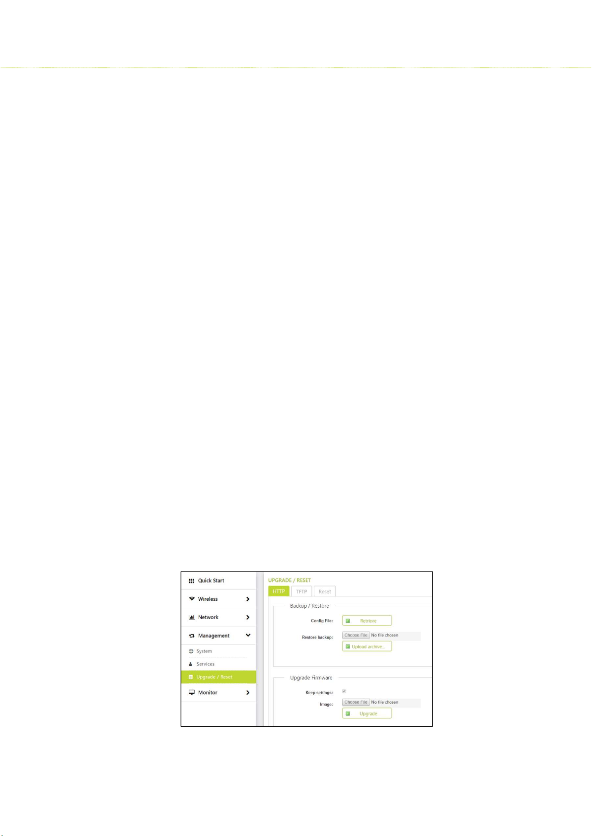
6.5 Upgrade/Reset
6.5.1 HTTP
• Backup & Restore
To configure Backup & Restore, Click Management > Upgrade/ Reset> HTTP >
Backup & Restore
This back-up option allows user to either download the device configuration
locally
The restore option allows user to restore the device configuration to the
uploaded configuration file.
Restoring the config file to the device will take 30 sec approx.
After uploading the configuration file, the device will load with the new
configuration
• Upgrade Firmware
To configure Upgrade Firmware, Click Management > Upgrade/ Reset > HTTP >
Upgrade Firmware
The firmware upgrade process happens in four phases:
Upload: Select firmware to be uploaded
Verification: Verify the firmware to validate the checksum
Upgrade: Write the new firmware into flash memory
Reboot: Once flash write processes is completed, and then automatically
reboot the device.
The whole firmware upgrade process takes around 6.30 minutes to
complete.
When upgrade process starts, all the existing links will be disconnected until
it reboots with new firmware.
Due to the above fact, it is recommended to upgrade all remote devices
and then upgrade the local devices.
42
Page 43
SMAC3 User Material
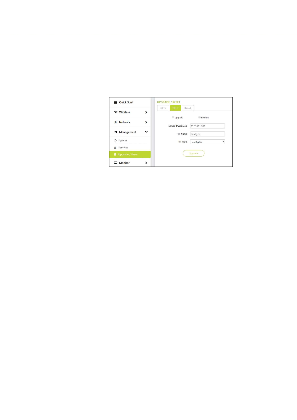
6.5.2 TFTP
To configure TFTP, Click Management > Upgrade/ Reset> TFTP > Upgrade / Retrieve
A Trivial File Transfer Protocol (TFTP) server lets you transfer files across a network.
By using TFTP, you can retrieve files from the device for backup or copying, and you
can upgrade the firmware or the configuration files onto the device.
Upgrade
Select Image from the drop down of file type and upgrade.
The firmware upgrade process happens in four phases:
The TFTP firmware is uploaded from PC TFTP server path to the device.
Verification: Verify the firmware to validate the checksum
Upgrade: Write the new firmware into flash memory
Reboot: Once flash write processes is completed, and then automatically
reboot the device.
The whole firmware upgrade process takes around 6.30 minutes to
complete.
When upgrade process starts, all the existing links will be disconnected until
it reboots with new firmware.
Due to the above fact, it is recommended to upgrade all remote devices
and then upgrade the local devices.
Retrieve
The retrieved device config file will be stored in the PC TFTP Server path.
43
Page 44
SMAC3 User Material
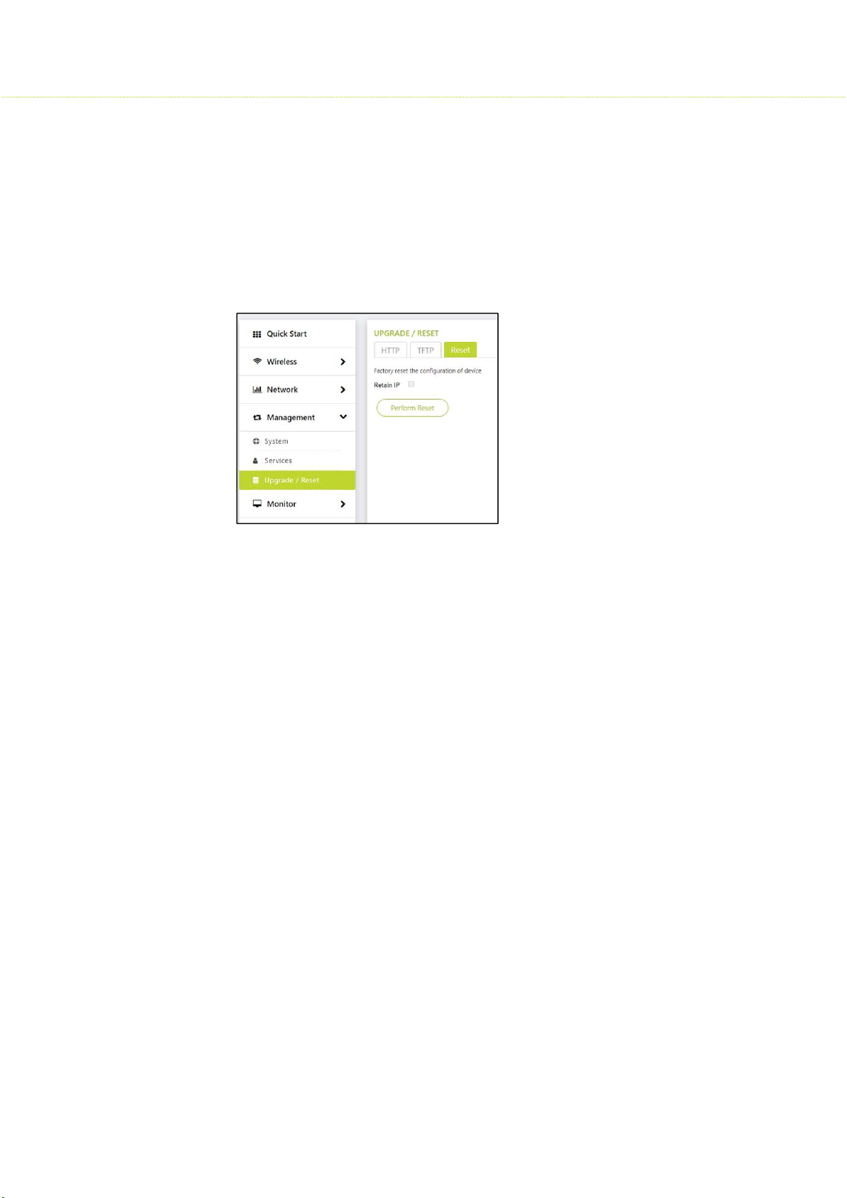
6.5.3 Reset
To Reset, Click Management > Upgrade/ Reset> Reset
This option allows user to reset all device configuration to factory defaults.
After reset, the device has to be accessed using the LAN interface locally and has to
be re-configured to allow the device to join into the network again.
Retain IP: If Retain IP is checked, the last IP before the reset will be recalled.
7 Monitor
7.1 Statistics
The objective of statistics page is to allow an administrator to view the state of wired and
wireless interfaces. These statistics assist the network administrator to troubleshoot the
devices.
7.1.1 5 GHz Radio:
You can view the details of associated devices connected to the 5 GHz Radio.
To view the 5 GHz Radio Statistics, click Monitor > Statistics > 5 GHz Radio
MAC Address: Displays the MAC address of the linked remote device
IPv4-Address: Displays the IP address of the remote device
Link Id: Displays the link Id of remote device
Distance (Km): Displays the distance between the AP and SU.
Local Signal (dB): Displays the local signal strength
Remote Signal (dB): Displays the Signal strength of the remote device
Rate (Mbps): Displays the Transmit (Tx) and Receive (Rx) rate of a al device
Throughput (Mbps): Displays the current Input and Output bandwidth
44
Page 45
SMAC3 User Material
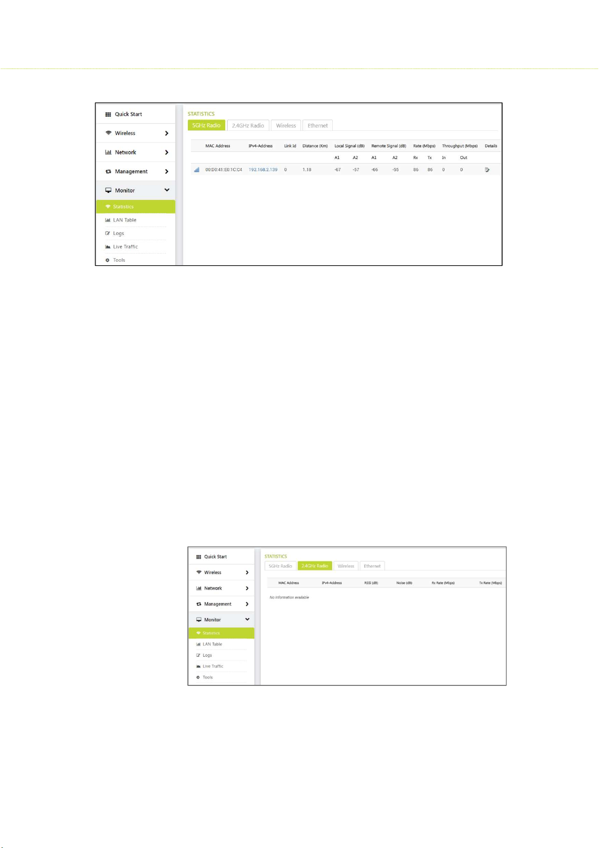
7.1.2 2.4 GHz Radio:
You can view the details of associated clients connected to the 2.4 GHz Radio
To view the 2.4 GHz Radio Statistics, click Monitor > Statistics > 2.4 GHz Radio
MAC Address: Displays the MAC address of the client that is connected
to the AP
IPv4-Address: Displays the IP address of the client
RSSI (dB): RSSI stands for Received Signal Strength Indicator. For
receiving strong signal, the RSSI should be high. This section displays the
Receiver statistics. It indicates the power viewed across the receiver
input.
Noise (dB): Refers to the noise level with which the AP received wireless
frames from the client
Rx Rate (Mbps): Rx Rate of received wireless from the Client to AP
TX Rate (Mbps): Tx rate of transmitted wireless from AP to Client
45
Page 46
SMAC3 User Material
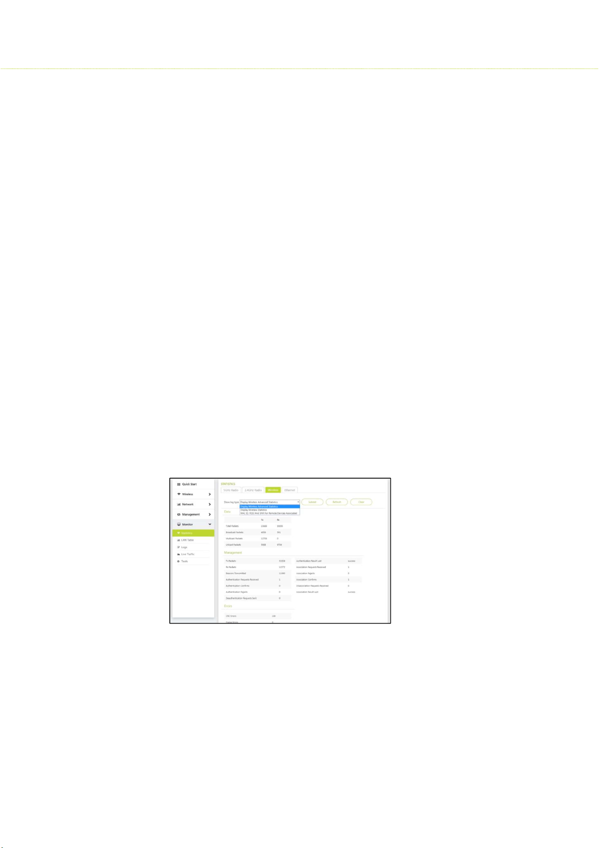
7.1.3 Wireless Statistics
You can view information about wireless network traffic.
To view the Wireless Statistics, click Monitor > Statistics > Wireless
Log Type:
Display Wireless Advance statistics
Display Wireless statistics: A summary of basic wireless statistics
MAC Id, RSSI and SNR for remote device associated
Display Wireless Advance statistics:
o Data: Specifies the total number of packets, broadcast
packets; multicast packets, unicast packets of both Tx and Rx.
o Management: Device Management features are summarized
o Errors: Displays CRC and Frame Errors
o CRC Errors: Specifies the number of received packets
with invalid CRC.
o Frame Errors: Too many frame errors cause network
connection slow.
Display Wireless statistics:
This consists of the values of Tx and Rx Packets, Number of errors occurred,
Link Quality, SNR, Number of retries etc.
MAC Id, RSSI and SNR for remote device associated
46
Page 47
SMAC3 User Material
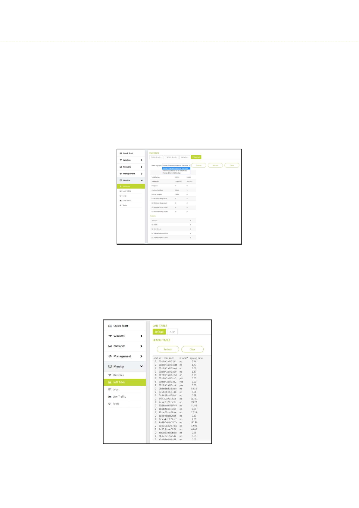
7.1.4 Ethernet
You can view information about wired Ethernet network traffic.
To view the Ethernet Statistics, click Monitor> Statistics > Ethernet
Log Type
1. Display Ethernet Advance statistics: Displays a summary of Tx, Rx, Errors, L2,
L3- Multicast& Broadcast drop count.
2. Display Ethernet statistics: A summary of basic Ethernet statistics (Tx, Rx,
collisions etc.)
3. Network statistics for all Interfaces: A summary of all wired and wireless
interfaces
7.2 LAN Table
To view the LAN Table Statistics, click Monitor > Statistics > LAN Table
7.2.1 Bridge
Learn Table:
Learn Table is used to view all the MAC addresses of a device on both wired and
wireless interfaces. The Learn Table
displays the information of port no,
MAC addresses, whether the type of
interface is local interface or not and
finally the aging timer as shown.
Click Refresh to get the updated or
latest Learn Table.
Click Clear to delete all entries of the
Learn Table.
47
Page 48
SMAC3 User Material
7.2.2 ARP
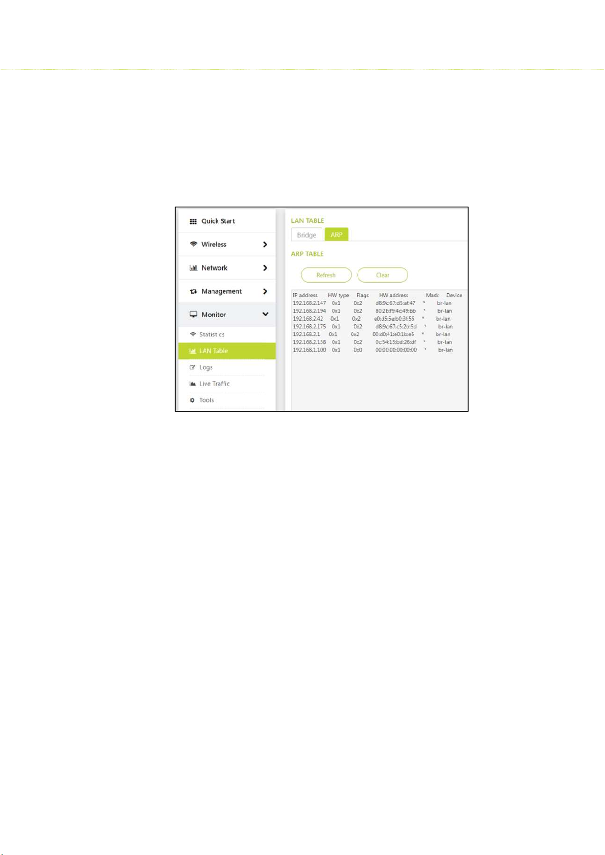
This section displays the mapping of the IP and MAC addresses of all nodes in the
network. This information is based upon the Address Resolution Protocol (ARP). ARP
is a L2 neighboring protocol which converts the IP address into a physical address
on the Ethernet network.
Click Refresh to get the updated or latest ARP Table.
Click Clear to delete all entries of the ARP Table.
7.3 Logs
Logs are the entries of wired and wireless interfaces.
7.3.1 Wireless
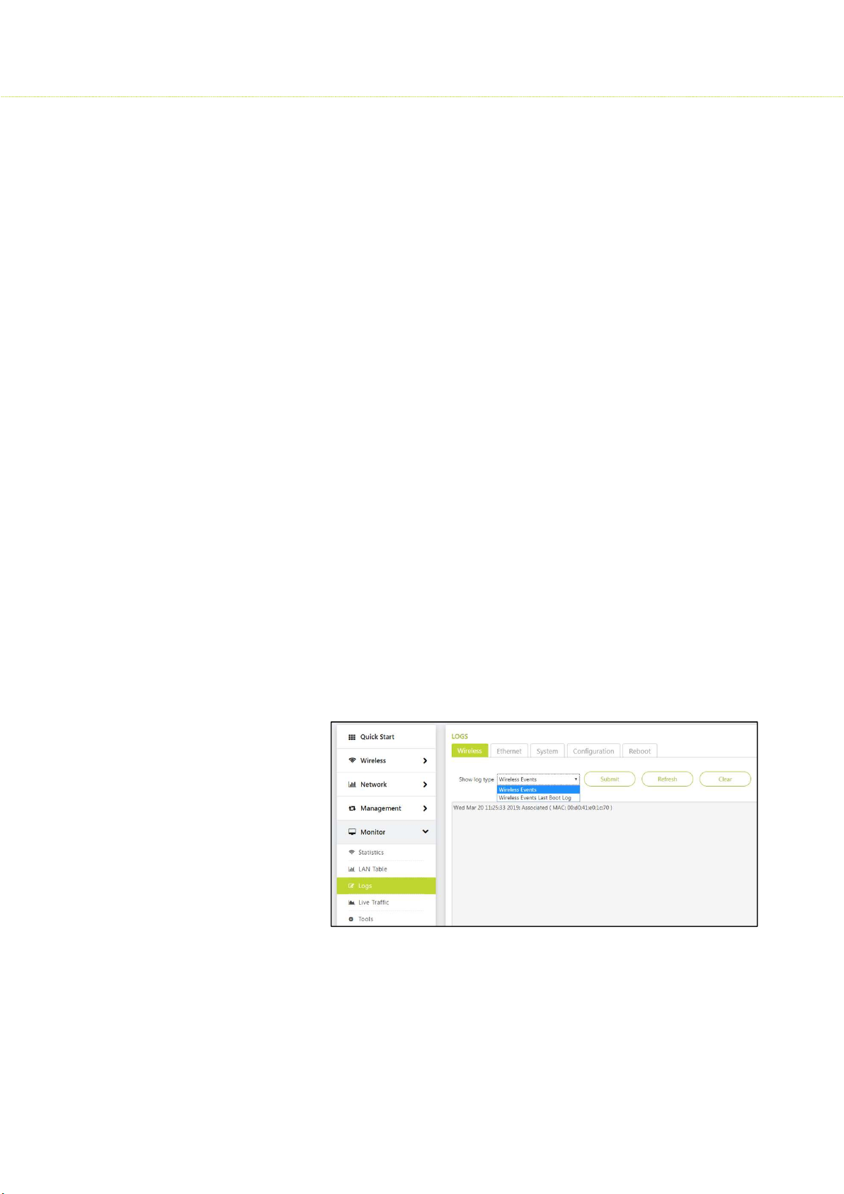
To view the Wireless logs, click Monitor > Logs> Wireless
The Log types are classified into
1. Wireless Events
2. Wireless Events Last Boot Log
I. Wireless Events:
Here the latest wireless event entries are displayed. Different types of
Logs are generated:
a) Associated Log: When an AP is connected to an SU or vice versa,
a log is generated which is called as Associated log. This log
consists of MAC Addresses of the remote device.
For example:
Sat Apr 13 07:12:53 2019: Associated (MAC: 00:d0:41:e0:1c:1c) in SU
Sat Apr 13 07:12:51 2019: Associated (MAC: 00:d0:41:e0:1c:04) in AP
48
Page 49
SMAC3 User Material
b) Disassociated log: When an AP is disconnected with an SU or vice
versa due to a reboot/soft reset/ a manual disconnect then a log
is generated which is called a disassociated log. This log consists
of MAC Addresses and a reason for disconnection of the device.
For example:
Sat Apr 13 07:15:46 2019: Disassociated (MAC:
00:d0:41:e0:1c:1c) in SU/ Remote Device
Sat Apr 13 07:15:45 2019: Disassociated (MAC:
00:d0:41:e0:1c:04, Reason: Local Terminated) in AP or BSU
Reasons that are displayed in the log are:
Locally terminated: If an AP is a local device and loses SU link or
vice versa due to a reboot/soft reset/ a manual disconnect, then
the termination reason is said to be locally terminated.
Remote terminated: if an SU is unable to connect to an AP, due to
a reboot/soft reset/ a manual disconnect, then the termination
reason is said to be Remote terminated.
Power Off: (Remote Device): If there is a power failure either in a
AP or SU. The termination reason is said to be Poweroff.
c) Wireless Inactivity: This parameter is configured only in SU, if there
is no activity on wireless interface of SU in a specified time interval,
reset the wireless interface. The value should be configured in
minutes. An event log is generated when wireless inactivity
triggers and this is visible in wireless events log.
d) Link Inactivity: If there is no activity on Wireless link on SU in a
specified time, reset the wireless interface. The value should be
configured in minutes. An event log is generated when Link
inactivity triggers and this is visible in wireless events log.
e) DCS logs:
49
Page 50
SMAC3 User Material
• This feature is available only in AP with 5GHz.
• Default chosen DCS threshold is 50%, when this percentage
limit exceeds, then a log is triggered and the AP activates
spectrum analyser and assigns best channel to the desired SU.
There are two types of logs generated:
• DCS Triggered log
• DCS best channel selection
• For example : <time stamp>: DCS triggered
<Time stamp>: DCS selected best channel
f) Spectrum Analyzer: has a start log and end log
II. Wireless Events Last Boot Log
When a proper reboot of a device takes place. The last saved logs are
displayed in the Wireless Events Last Boot Log.
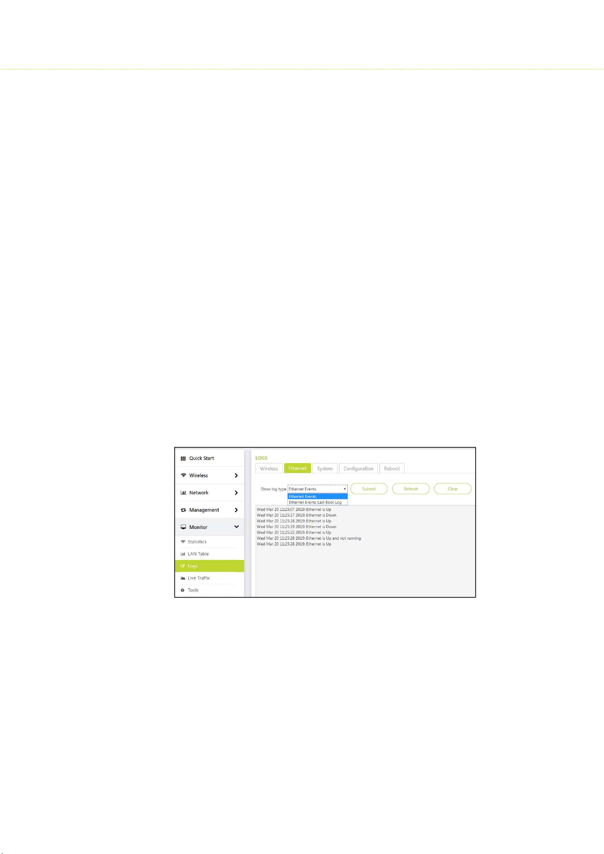
7.3.2 Ethernet
To view the Ethernet logs, click Monitor > Logs> Ethernet
Current Ethernet events and last reboot Ethernet events are logged in the
Ethernet log.
It consists of wired connection up, down and Ethernet inactivity.
50
Page 51
SMAC3 User Material
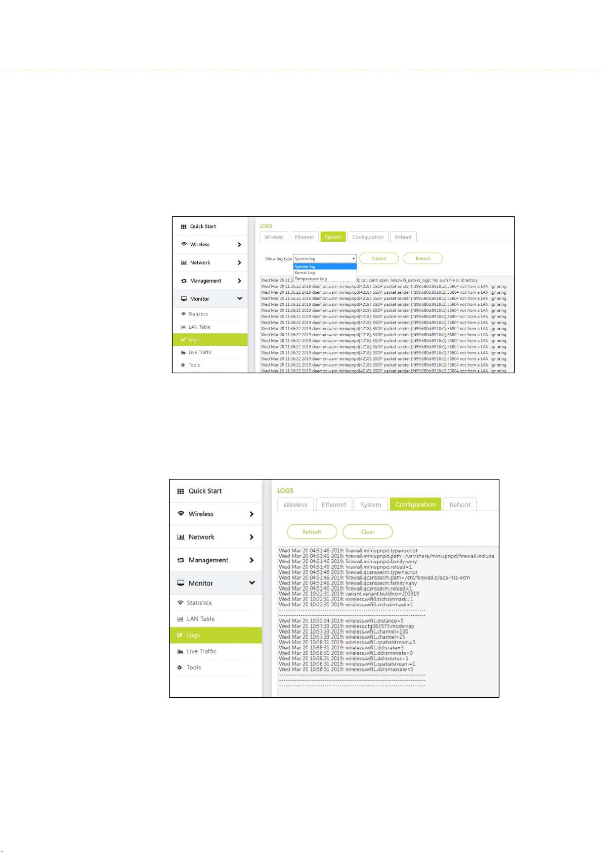
7.3.3 System
To view the System, click Monitor > Logs> System
All the system level, kernel level, temperature logs are displayed here.
Note: Temperature logs are recorded only after a certain temperature login
interval.
7.3.4 Configuration
To view the Configuration log, click Monitor > Logs> Configuration
Any recent changes in the device configuration are reflected here.
51
Page 52
SMAC3 User Material
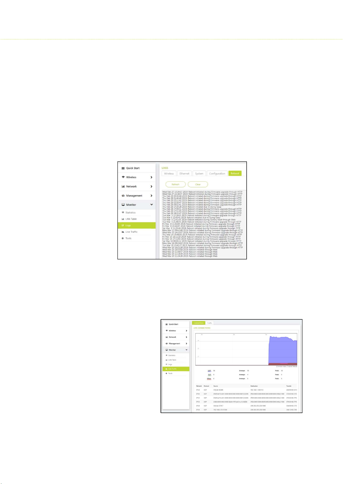
7.3.5 Reboot
To view the Reboot log, click Monitor > Logs > Reboot
A log is generated when the below condition takes place
When a device is manually rebooted through: Web, CLI, SNMP
When a device is reset to factory defaults through: Web, CLI, SNMP
When a device is upgraded firmware through: HTTP, TFTP
When a device is power off
7.4 Live Traffic
To view the Live Traffic, click Monitor > Statistics > Live Traffic
7.4.1 Live connections
Live TCP, UDP are
summarized in a graphical
representation
52
Page 53
SMAC3 User Material
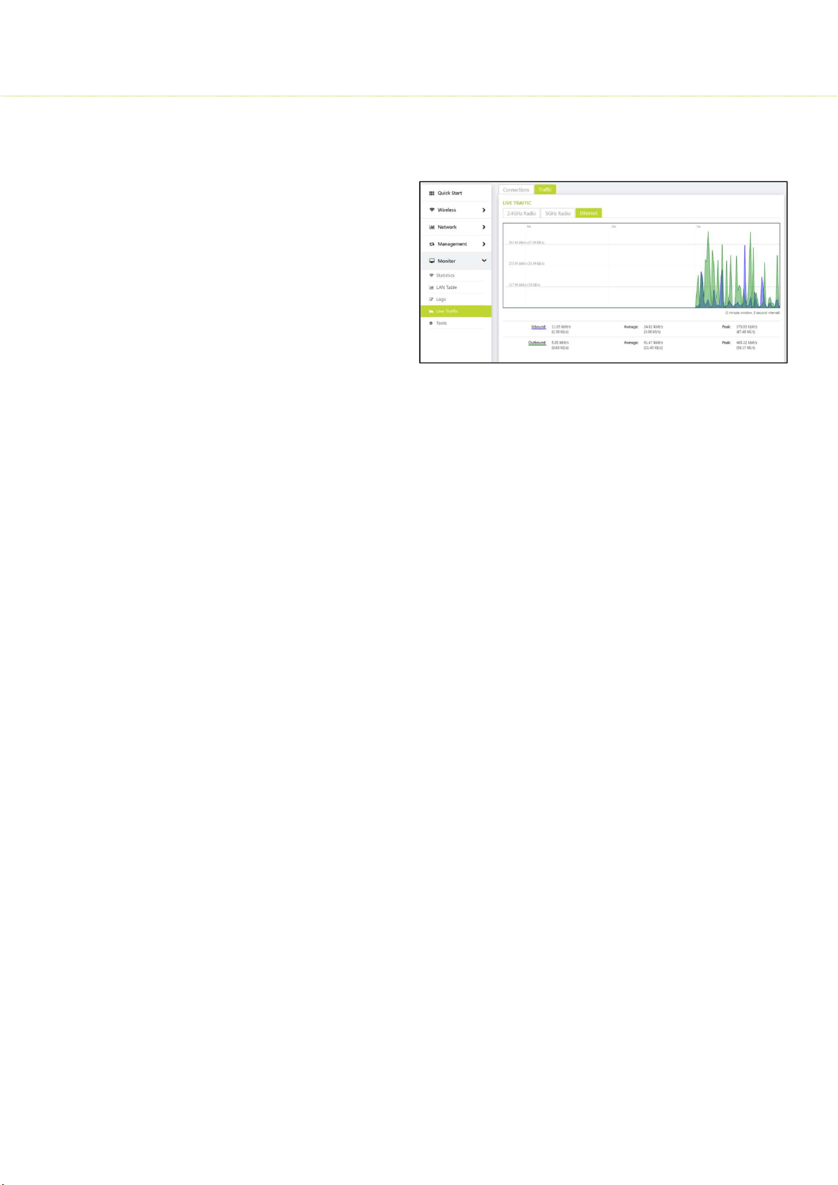
7.4.2 Traffic
2.4GHz Radio wireless
traffic is graphed
5 GHz Radio wireless
traffic is graphed
Ethernet Traffic on
Ethernet is summarized
7.5 Tools
To view the Tools, click Monitor> Statistics > Tools
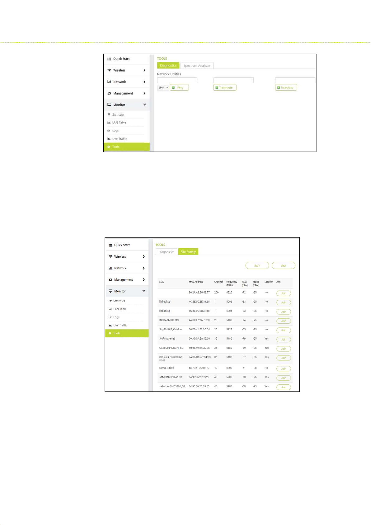
7.5.1 Diagnostics
Few popular network utilities are used to determine the network connections.
Ping: The main purpose of using this command is to verify the device can connect
over the network to another device or not.
Trace route: Trace route determines that the packet has reached the destination by
including a port number that is outside the normal range. When it is reached,
the Port Unreachable message is sent in return, which defines the time length of
the final hop. Trace route provides you with the information hop by hop. Each hop
is determined three times. When a website is unreachable or slow, trace route
allows you to see where the connection fails or has delays.
Nslookup: The Nslookup command is a DNS lookup utility
Example: nslookup hostname nameserver (nameserver address or nameserver IP
address) - provides you with a DNS record stored in the specified DNS server.
53
Page 54
SMAC3 User Material
7.5.2 Site Survey: This is available only in SU
Site Survey is for SU 5GHz Radio where it can scan and join the AP with the same
SSID.
Once the Access Point parameters were configured, the subscriber unit will scan
and get parameters updated from the AP. This way SU’s basic configuration will be
updated and further need to be monitored
54
Page 55
SMAC3 User Material
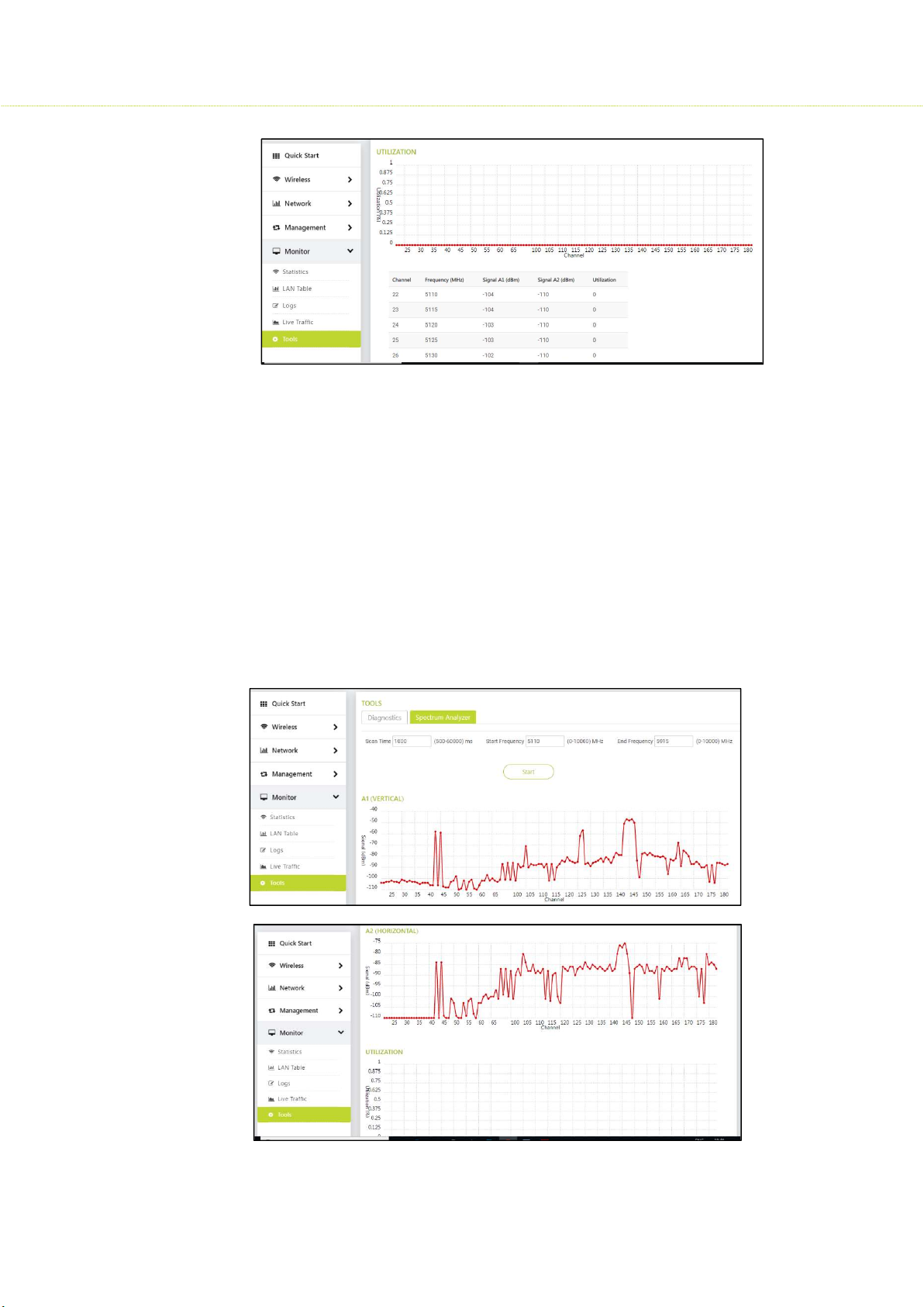
7.5.3 Spectrum Analyser: This is available only in AP
Scans all the frequencies from the configured start frequency to end frequency for
a specified scan time.
Click Start button and the results will be displayed in a graph:
A1 Vertical shows signal strength received on antenna A1 at each frequency.
A2 Horizontal shows signal strength received on antenna A2 at each frequency.
Utilization: This shows the max utilization of the medium at each frequency in
percentage.
55
Page 56

Product Models
Part Numbers
Descriptions
SMAC3
API-18-5G-AC2x2
-W2Outdoor AP with 18 dBi 60
-
degree sector antenna
APX-EX-5G-AC2x2
-W2Outdoor AP with 2 N
-
Type connectors
Hardware
Memory
DDR 256 MB, Flash 32 MB
GPS On board GPS info via
I2C,1PPS pulse
Dying Gasp
20ms (Max)
On Side LEDs
Green colour LEDs
Connector
Power source
48V 0.5A
length
MIMO
2 X 2 :2
Scheme
Channel Bandwidth
20 / 40 / 80 MHz
Channel Spacing
5 MHz
Transmit Power
Control
1 -
26 dB, in 1 dB steps. Automatic TPC with configurable EIRP limit
Max. Throughput
Up to 650 Mbps (5 GHz)
Integrated
18 dBi 60 degree sector | 18 dBi panel antenna | 23 dBi panel antenna
Technical Specifications
SUI-18-5G-AC2x2-W2 Outdoor AP with 18 dBi panel antenna
SUI-23-5G-AC2x2-W2 Outdoor AP with 23 dBi panel antenna
Chip set Qualcomm IPQ4018, Quad-Core 717 MHz CPU, 4x ARM Cortex A7
Thermal Sensor Supported
PoE Injector Passive 48V, 0.5A, +50C, 6KV Surge Protection
SMAC3 User Material
Ethernet
Enclosure Material ROHS compliant (non-metallic )
Supported with LED indication (2 LEDs on RJ-45)
Ethernet
Ethernet 1 x GbE Port, 6KV Surge Protection
Speed 10/100/1000Mbps, Half/Full Duplex, Auto Negotiation
STP Cat5e Cable
FTP Cat6 Cable
length
Wireless
Modulation
Frequency Band 4.9 GHz 5.1 GHz - 5.925 GHz 2.4 GHz
Max Transmit
Power
Max 130 meters
Max 180 meters
BSPK, QPSK, 16QAM, 64QAM, 256QAM
Public Safety Broadband Connectivity Radio Management
Upto 26 dBm (Combined)
Antenna
External 2 N-Type connectors
Security
Encryption AES 128 / 256
Authentication Internal MAC Address Control List, Radius based Authentication
QoS
56
Page 57

Bandwidth Control
Capabilities
Scheduling
Best Effort, Real Time Polling Services
Network
IP Stack
IPv4, IPv6
Gateway Features
DHCP Server, NAT, IP sec
VLAN
802.1Q: Management VLAN, Transparent, Access, Trunk, QinQ
101.5mm
mm
229.2 x 250 x 80 mm
Weight
2.4 kgs/ 5.48 lbs
1 .2Kgs / 2.7 lbs
1.2Kgs / 2.7 lbs
1.68 kgs/ 3.7lbs
Environmental
Operating Temperature Storage Temperat
ure Humidity & IP Rating Wind loading
20/40 MHz
Asymmetric
SMAC3 User Material
Asymmetric UL/DL committed and maximum information rate per SU
Packet
Classification
Management
Remote Telnet, SSH, Web, TFTP
SNMP SNMP v1 / v2c / v3, RFC-1213, Private MIB
Modes Bridging, Routing
Physical Specs
Models API-18-5G-AC2x2-W2 APX-EX-5G-AC2x2-
Dimensions 371.3 x 371.3 x
802.1p priority, IPTOS, VLAN ID, IP addresses, ports, Ethernet addresses, IP protocol, and Ether
Type
SUI-18-5G-AC2x2-W2 SUI-23-5G-AC2x2-W2
W2
229.2 x 250 x 80
-20 to +65 °C -50° to +70 °C 95% maximum 180 kmph
(-58° to 158° F) Non-Condensing, IP67
Maximum Transmit
Power (20/40 MHz)
Receiver Sensitivity
MCS0: 23 dBm MCS8: 23 dBm MCS0: 23 dBm MCS8: 23 dBm
MCS1: 23 dBm MCS9: 23 dBm MCS1: 23 dBm MCS9: 23 dBm
MCS2: 23 dBm MCS10: 23 dBm MCS2: 23 dBm MCS10: 23 dBm
MCS3: 23 dBm MCS11: 23 dBm MCS3: 23 dBm MCS11: 23 dBm
MCS4: 23 dBm MCS12: 23 dBm MCS4: 23 dBm MCS12: 23 dBm
MCS5: 22 dBm MCS13: 22 dBm MCS5: 22 dBm MCS13: 20 dBm
MCS6: 21 dBm MCS14: 20 dBm MCS6: 21 dBm MCS14: 20 dBm
MCS7: 20 dBm MCS15: 20 dBm MCS7: 20 dBm MCS15: 20 dBm
2.4 GHz 5 GHz
305.5x305.5x79.5mm
MCS0: -92 dBm MCS8: -90 dBm MCS0: -92 dBm MCS8: -90 dBm
MCS1: -90 dBm MCS9: -88 dBm MCS1: -90 dBm MCS9: -88 dBm
MCS2: -87 dBm MCS10: -86 dBm MCS2: -87 dBm MCS10: -86 dBm
MCS3: -84 dBm MCS11: -83 dBm MCS3: -84 dBm MCS11: -83 dBm
MCS4: -81 dBm MCS12: -80 dBm MCS4: -81 dBm MCS12: -80 dBm
MCS5: -78 dBm MCS13: -76 dBm MCS5: -78 dBm MCS13: -76 dBm
MCS6: -75 dBm MCS14: -73 dBm MCS6: -75 dBm MCS14: -73 dBm
MCS7: -72 dBm MCS15: -70 dBm MCS7: -72 dBm MCS15: -70 dBm
2.4 GHz 5 GHz
Package Contents
1 Radio
1 PoE Injector with AC Power Cable
1 Ethernet Cable Cat5e 1.5 mts
1 Grounding Cable 1.8 mts AWG10
57
Page 58

SMAC3 User Material
Certification
MTBF & Warranty
MTBF over 250 000 hours & 1
-
year warranty
Description
W2
W2
1 Pole Mounting Kit or Axis Mounting Kit (Based on the radio model)
1 Quick Installation Guide
Ordering
Information
Part Number
API-18-5G-AC2x2-
APX-EX-5G-AC2x2W2
SUI-18-5G-AC2x2-
SUI-23-5G-AC2x2W2
FCC: 47 CFR Part 90, Sections 90.1201 through 90.1217
FCC: 47 CFR Part 15, Subpart C (Section 15.247)
FCC: 47 CFR Part 15, Subpart E (Section 15.407)
FCC: Part 2(Section 2.1091)
IEC 61000-4-2: 2008, IEC 61000-4-4: 2012, IEC 61000-4-6: 2013
CISPR 22: 2008 Class A: Radiated Disturbance
IEC 61000-4-3 Class A: Radiated Susceptibility
IEC 61000-4-11 Class A: Voltage Dips & Interruption
IEC 61000-4-5 +/-6kV Class A: Surge Test on AC-Input and PoE Data lines
Outdoor AP with 18 dBi 60 degree sector antenna
Outdoor AP with 2 N-Type connectors
Outdoor AP with 18 dBi panel antenna
Outdoor AP with 23 dBi panel antenna
SIFY TECHNOLOGIES LIMITED
2nd Floor, Tidel Park
4. Rajiv Gandhi Salai, Taramani
Chennai – 600 113
Phone: +91 44 2254 0770-77
Fax: +91 44 2254 077
58
 Loading...