

Sifam Tinsley Zeta 30 User Manual
User Manual
Analog-Digital Multimeter with Insulation Resistance Measurement
Zeta 30
IC 2-60-006-00-00551/REV-A/10/2014
Printed in India, Subject to change without Notice
Sifam Tinsley Instrumentation Ltd.
Central Buildings, Woodland Close,
Old Woods Trading Estate,
Torquey, Devan, England, TQ27BB
Website: www.sifamtinsley.com/uk
Contact Number: +44(O) 1803 615139
E-mail: info@tinsley.co.uk
Sifam Tinsley Instrumentation
3105, Creekside Village Drive,
Suite No 801,Kennesaw,
Georgia 30144
Contact Number: +1.404.736.4903
Web: www.sifamtinsley.com
P R EC I S I O N IN S T R U ME N T A T IO N

(8)
(9)
(10)
(11)
(12)
(16)
(15)
(14)
(13)
(18)
(17)
(19)
VA
MIN
MAX
DC
AC
ON
-8.8.8.8
10
0
20
30
MAN DATA
KW MW
kHz
%
0
C
mF
nF
mm
+
+
5
ON
(1)
(2)
(3)
(4)
(5)
(6)
V
DC AC
20.16
(7)
10
0
20
30
MAN
MAX
VINSU
1
Icap
(Iea)
DATA
MIN / MAX
OFF
Func
INSU
mA
1000V
300mA
1000V
fused
1000V CATII/600V CATIII
IEC 61010-1
INSU
INSU
TRMS MULTIMETER
INSULATION TESTER
AUTO
MAN
ON
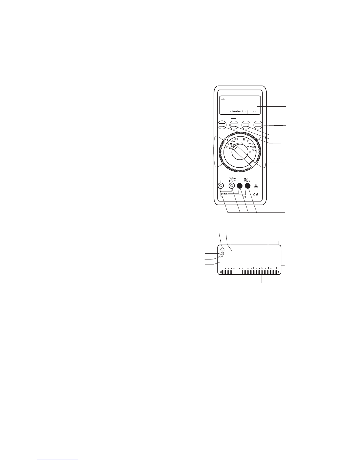
(1) Liquid crystal display
(2) ON/OFF pushbutton
(3) Pushbutton for data hold
and MIN/MAX storage functions
(4) Pushbutton for manual range
selection
(5) Multi function pushbutton
(6) Function selector switch.
(7) Terminal sockets with automatic
blocking system.
(8)Symbol for’’CONTINUOUSLY ON"
(9)Display for digits, decimal point and
polarity.
(10) Display for manual range selection,
DATA hold and MIN/MAX storage.
(11) Display for the selected function
(12) Display for the unit of
measured quantity.
(13) Over range indication for
positive analog range.
(14) Pointer for analog indication.
(15) Scale for analog indication
(16) Over range indication for
negative analog range.
(17) Low battery indication.
(18) Buzzer indication
(19)
Display for temperature
0
C
measurement range.

1
Contents Page
1. Introduction
...............................................................................
2.
Safety features and safety precautions..............................................
3. Switching the multimeter "ON"............................................................
4.
Function and range selection..............................................................
4.1 Switching the DC current measuring ranges........
.....................................
4.2 Autoranging
...............................................................................
4.3
Manual range selection.......................................................................
5
Liquid crystal display...........................................................................
5.1 Digital display
...............................................................................
5.2
Analog indication ................................................................................
6.
”DATA ” hold facility..............................................................................
7.
Minimum value and maximum value “MIN/MAX” storage facility
...............
8.
Voltage measurement.........................................................................
8.1 Voltage measurement on electrical system upto 1000V
with the KS30 measuring adapter........................................................
9.
Current measurement.........................................................................
9.1
AC current measurement with (clip-on) current transformers.....................
10.
Resistance measurement...................................................................
11.
Diode test and continuity test..............................................................
12.
Capacitance measurement ...............................................................
13. Frequency measurement ...................................................................
14. Duty cycle measurement ...................................................................
15. Temperature measurement ................................................................
16. Insulation resistance measurement ...................................................
18.1
Battery.................................................................................................
18.2
Fuses..................................................................................................
18.3
Case...................................................................................................
19 Servicing.............................................................................................
5.3
Backlit (optional) .................................................................................
16.1 Before measurement .........................................................................
16.2 Selecting Test Voltage .......................................................................
16.3 Insulation Resistance measurement .................................................
16.4 After Insulation measurement ...........................................................
17. Specifications
................................................................................
18. Maintenance
.................................................................................
16.5 Evaluation of measurement values ...................................................
2
2
3
4
4
4
5
5
5
5
6
6
6
7
9
9
11
11
13
14
15
15
16
17
17
17
17
18
18
19
27
27
28
28
28
INDEX
2
1. Introduction:
Thank you very much for selecting our multimeter. We are the leading
manufacturer of Electrical and Electronics measuring instruments. These
multimeters are manufactured as per IS 13875 and DIN 43751.
2. Safety features and safety precautions
You have chosen a multimeter which provides you a very high degree of
safety. This meter is manufactured and tested in compliance with the safety
standard IEC 61010-1:2001/ DIN EN61010 -1:2001 and IEC61557.
In case of incorrect use or careless handling, the safety of both user and
multimeter is not assured.
For proper use and safe handling, it is absolutely necessary to read and
understand the operating instructions before using the meter.
For your safety and for protection of the multimeter, this meter is fitted with an
Automatic terminal Blocking System (ABS).
It is coupled with the function selector switch which blocks the Terminal
sockets not necessary for measurement.
Please note the following safety precautions:
l The multimeter must be operated only by persons who understand the
danger of shock hazards and are aware of the necessary safety
precautions. Shock hazards exist wherever voltages of more than 30V
(TRMS) are present.
l Do not work alone in shock hazardous environment while carrying out
measurement.
l The maximum permissible voltage between terminal Socket (7) and
ground is 1000 V.
l Take into account that unexpected voltages can occur on device under
test (e.g. defective instrument). For example, capacitors may be
charged to a dangerously high voltage.
l Verify that the test leads are in good condition, e.g.no cracked insulation,
no open circuits in the leads or connectors.
l This multimeter must not be used for measurements on circuits with
corona discharge (high voltage).
l Be particularly careful when measuring on HF circuits. Dangerous
composite voltages may exist there.
l Measurements under moist environmental conditions are not Permitted.
l Do not overload the measuring ranges beyond their allowable
capacities. Limit values are given in specifications Refer Chapter 17.
l All current measuring ranges, are protected with fuse. The maximum
permissible voltage of the measuring circuit (=nominal voltage of the
fuse) is1000 VAC/DC in “mA” ranges.
WARRANTY
Dear Customer,
You are now the privileged owner of Zeta 30 Analog-Digital / Multimeter a
product that ranks the first of its kind in the world. Company provides 12
months warranty from the original date of Purchase against defective
material and workmanship.
In the unlikely event of failure of the instrument / accessories within the
warranty period. Company will repair meter / accessories free of charge.
Please hand over the meter / accessories to the dealer / stockist from whom
you have purchased along with this card and relevant Cash Memo / Invoice.
This warranty entitles you to bring the meter / accessories at your cost to the
nearest stockist / dealer and collect it after repairs.
NO TRANSPORTATION CHARGES WILL BE REIMBURSED.
The warranty is not valid in following cases:
1. Warranty card duly signed and stamped and original Cash Memo / Invoice
is not sent along with Meter.
2. Complete warranty card is not presented to authorised person at the time
of repairs.
3. Meter / accessories is not used as per the instructions in the instruction
manual.
4. Defect caused by misuse, negligence, accidents, tampering and Acts of
God.
5. Improper repairing by any person not authorised by the company.
6. Modification, Alteration of any sort is made in electrical circuitry.
7. Seal provided inside/outside is broken.
Warranty of Zeta 20 accessories does not cover Fuses, Battery & Mains
Adapter.
In case of dispute to the validity of the warranty, the decision of Company
service center will be final.
If you bought this Meter directly from the company, and if you notice transit
damage, then you must obtain the insurance surveyors report and forward it
to Company .
Thank you.
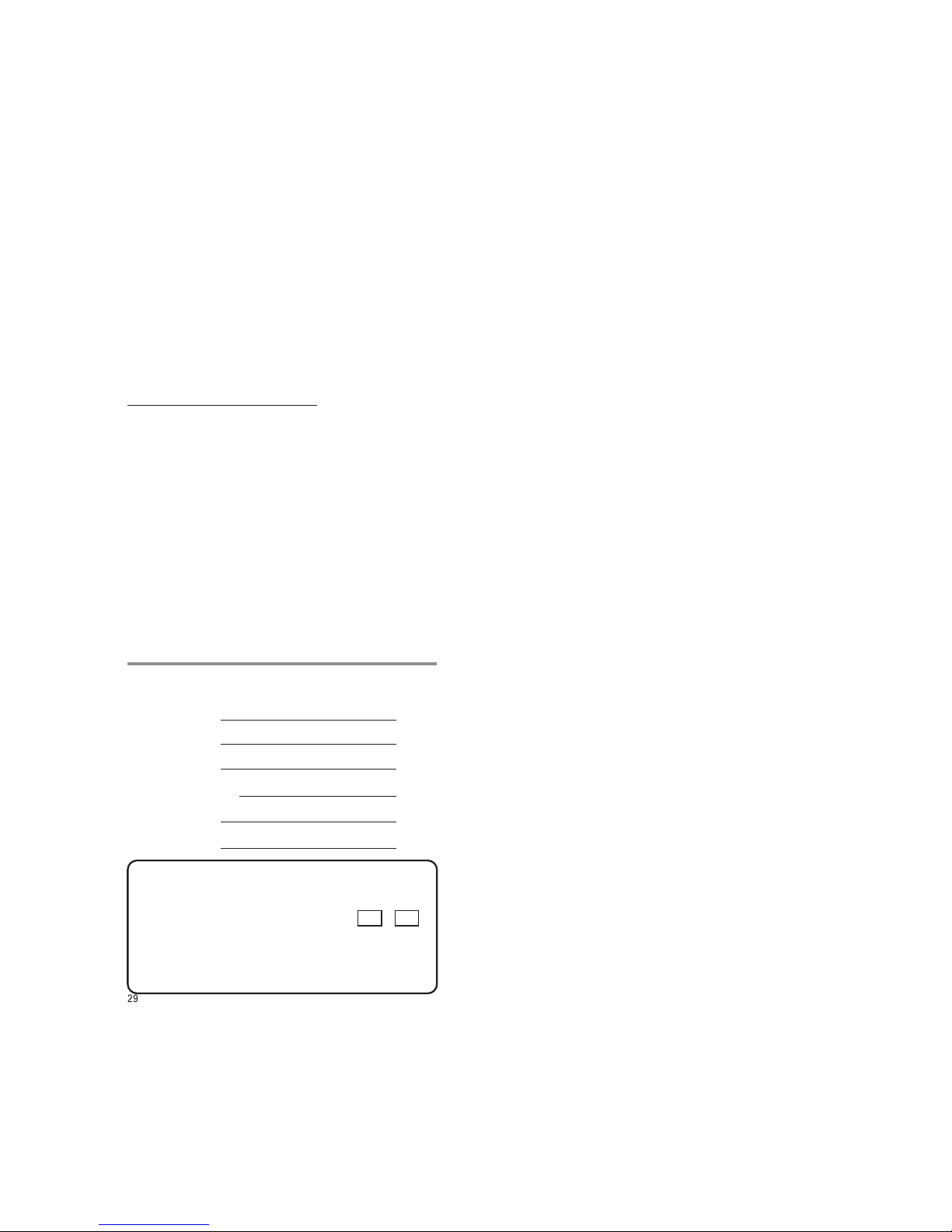
(To be filled by authorized dealer)
Model No. :
Serial No. :
Date of Purchase :
Cash Memo / Invoice No. :
Dealer’s Signature :
Dealer’s Stamp :
Scope of Supply
1) Instrument 2) Cable Set
3) Spare Fuse 4) Safety Cover
5) 1.5 V Battery 6 Nos. - Rechargeable - Yes No
6) User Manual 7) Warranty Card
8) Crocodile Clips 9) Belt

3
Note:
Electric discharges and high-frequency influence may cause incorrect
information to be displayed and block the measuring process. Reset the meter
by switching it OFF and ON again otherwise, check the battery connections.
Repair, replacement of parts:
When opening the meter, live parts may be exposed. Therefore, the meter
must be disconnected from the measuring circuit prior to opening its case for
repair or replacement of parts. If repair cannot be avoided unless the meter is
opened and live, this work must only be performed by a qualified person who
understands the danger involved.
When it is realised that the safe operation is no longer possible, take the meter
out of service and secure it against accidental use.
Safe operation may not be possible,
l when the meter shows obvious signs of damage,
l when the meter no longer functions correctly,
l after prolonged storage under adverse conditions,
l due to severe stress during transportation.
3. Switching the multimeter "ON”
Battery
We have already fitted your meter with a 1.5V x 6 (AAA size)batteries
according to IEC 6 LR 03. It is ready for operation.
for the first time or after storage, refer to Section "18.1 Maintenance-Battery".
Before you use the meter
Switching the meter "ON”
Press the "ON/OFF" pushbutton (2).
Switch-"ON" is acknowledged by a sound signal. As long as you keep
the pushbutton pressed, all segments of the liquid crystal display (LCD)
will appear. The LCD is shown on page before 1.
After the pushbutton is released, the meter is ready for operation.
l
l For safe transient voltage measurements in power systems upto
1000V, we recommend the KS30 measuring adapter, which is
available as an accessory. Its internal resistance limits the
measuring current in the case of over voltage, in correct operation
and safely suppresses sparking from spark gap. Also refer to
Section “8.1 Voltage measurement” on electrical systems up to
1000V with KS30 measuring adapter.
Meaning of the symbols on the device
Warning of a danger point
(Attention, refer to the user manual)
Earth (ground) terminal.
Double or reinforced insulation
Instrument for over voltage
category II / III or IV
EU conformity mark.
CAT II / III / IV
28
19. Servicing
When you need service, please contact :
Replacing the battery
Ÿ Place the multimeter on its face, loosen the two screws on the rear and
remove the lower part of the case, lifting it from the bottom. The lower and the
upper part of the case are fixed together at the top on the front by means of
wedges.
Ÿ Remove all six batteries from the battery holder.
Ÿ Place six new batteries into battery holder with correct polarities.
Ÿ Replace the lower part of the case. Start at the top on the front and take care
that the wedges are properly engaged at this point.
Ÿ Tighten the lower part with the two screws.
Ÿ Please destroy the batteries in an environment friendly way.
18.2 Fuses
A blown fuse is signalled on the LCD display the instant a measured quantity
having a voltage of more than 4 V is applied to the corresponding connection
sockets.
Then, the digital display (9) shows "FUSE"
The 1.6 A protects all other current measuring ranges. All other measuring
ranges continue to function.
When a fuse blows, first eliminate the cause of the overload using the multimeter
again !
Fuse replacement
Ÿ Open the multimeter same as for battery replacement
Ÿ Remove the blown fuse, e.g. with the aid of a probe, and replace it with a
new one.
Ø Permissible types for current measuring ranges up to 300 mA:
FF (UR) 1.6 A / 1000 V AC/DC; (10 KA); 6.3 mm x 32 mm
Caution :
Absolutely verify that only the specified fuse is installed!
If a fuse of other cut-out capacity, other nominal current or other switching capacity
is used, a dangerous situation exists, and there is danger of damaging protective
diodes, resistors or other components.
The shorting of the fuse holder is not permissible.
18.3 Case
Special maintenance of the case is not required. Take care that the surface
between the connection sockets is clean. For cleaning take a moist cloth.
Avoid scrabbing.
Sifam Tinsley Instrumentation Ltd.
Central Buildings, Woodland Close,
Old Woods Trading Estate,
Torquey, Devan, England, TQ27BB
Website: www.sifamtinsley.com/uk
Contact Number: +44(O) 1803 615139
E-mail: info@tinsley.co.uk
Sifam Tinsley Instrumentation
3105, Creekside Village Drive,
Suite No 801,Kennesaw,
Georgia 30144
Contact Number: +1.404.736.4903
Web: www.sifamtinsley.com
The Information contained in these installation instructions is for use only by installers
trained to make electrical power installations and is intended to describe the correct method
of installation for this product.
It is the user's responsibility to determine the suitability of the installation method in the
user’s field conditions.
 Loading...