

Sifam Tinsley Theta 30P Operating Manual
POWER \ PHASE ANGLE \ POWER FACTOR TRANSDUCER
2-60-006-00-00538
Operating Manual
Theta 30P
Rev.C - 31/5/13
O
N O
1 O
/P
2
/P
CO
M
T
h a P
e
t
3
0


CAUTION
The proper and safe operation of the device assumes
that the Operating Instructions are read and the safety
w a r n i n g s g i v e n in th e va r i o u s se c t i o n s
Mounting,Electrical Connections, Commissioning are
observed.
All operations concerning installation, electrical
connection & commissioning must be carried out by
qualified, skilled personal & national regulations for the
preventions of accidents must be observed.
If the equipment is used in used in a manner not specified
by the manufacture, the protection provided by the
equipment may be impaired.
Read & understand this manual before using the Instrument
3

POWER \ PHASE ANGLE \ POWER FACTOR TRANSDUCER
Installation
& Operating Instructions
Section
Contents
1. Introduction
2. Input and Output screens
3. Programming
3.1 Programming Via Front LCD & Two keys
3.1.1 Password Protection
3.1.1.2 Editing Existing Password
3.1.1.1 Password Verification
3.1 Parameter Setting .7 Communication
3.1.7.1 Address Setting
3.1.7.2 RS 485 Baud rate
3.1.7.3 RS 485 Parity selection
3.1.6 Current Parameter Setting Transformer
3.1 Transformer.6.2 Current Secondary Value
3.1.6.1 Current Transformer Primary Value
3.1.5 Potential Transformer Parameter Setting
3.1 Potential Transformer.5.2 secondary value
3.1.5.1 Potential Transformer primary value
POWER \ PHASE ANGLE \ POWER FACTOR TRANSDUCER
4
3.1.3 System Type Selection
3.1.4 Output Type Selection
3.1.4.1 Output 1 Type Selection
3.1.4.2 Output 2 Type Selection
3.1.2 Transducer Type Selection

3.1 Output Characteristics setting.9
3.1 .1 Output 1 Characteristics setting.9
3.1.9.1.1 End value of output 1
3.1.9.1.2 Start value of output 1
3.1.9.1.3 Elbow value of output 1
3.1 .2 Output 2 Characteristics setting.9
3.1.9.2.1 End value of output 2
3.1.9.2.2 Start value of output 2
3.1.9.2.3 Elbow value of output 2
3.1.10 Mode Selection
3.2
Programming Via Programming port available at front of
Transducers using optional PRKAB601 Adapter
3.3
Programming Via optional RS485
RS 485 Modbus ( )
4.
Phaser Diagram
5.
6. Installation
6.1
EMC Installation Requirements
6.2
Case Dimensions
6.3
Wiring
6.4 Auxiliary Supply
8.
Connection Diagrams
6.5 Fusing
6.6 Earth / Ground Connections
Specifications
7.
3.1 Input Setting.8 Characteristics
3.1.8.1 End value of Input
3.1.8.2 Start value of Input
3.1.8.3 Elbow Function Selection
3.1.8.4 Elbow value of input
5
DIP Switch Setting for Changing Output type
3.3.1
(MODBUS)
communication port.
6.7 Maintenance
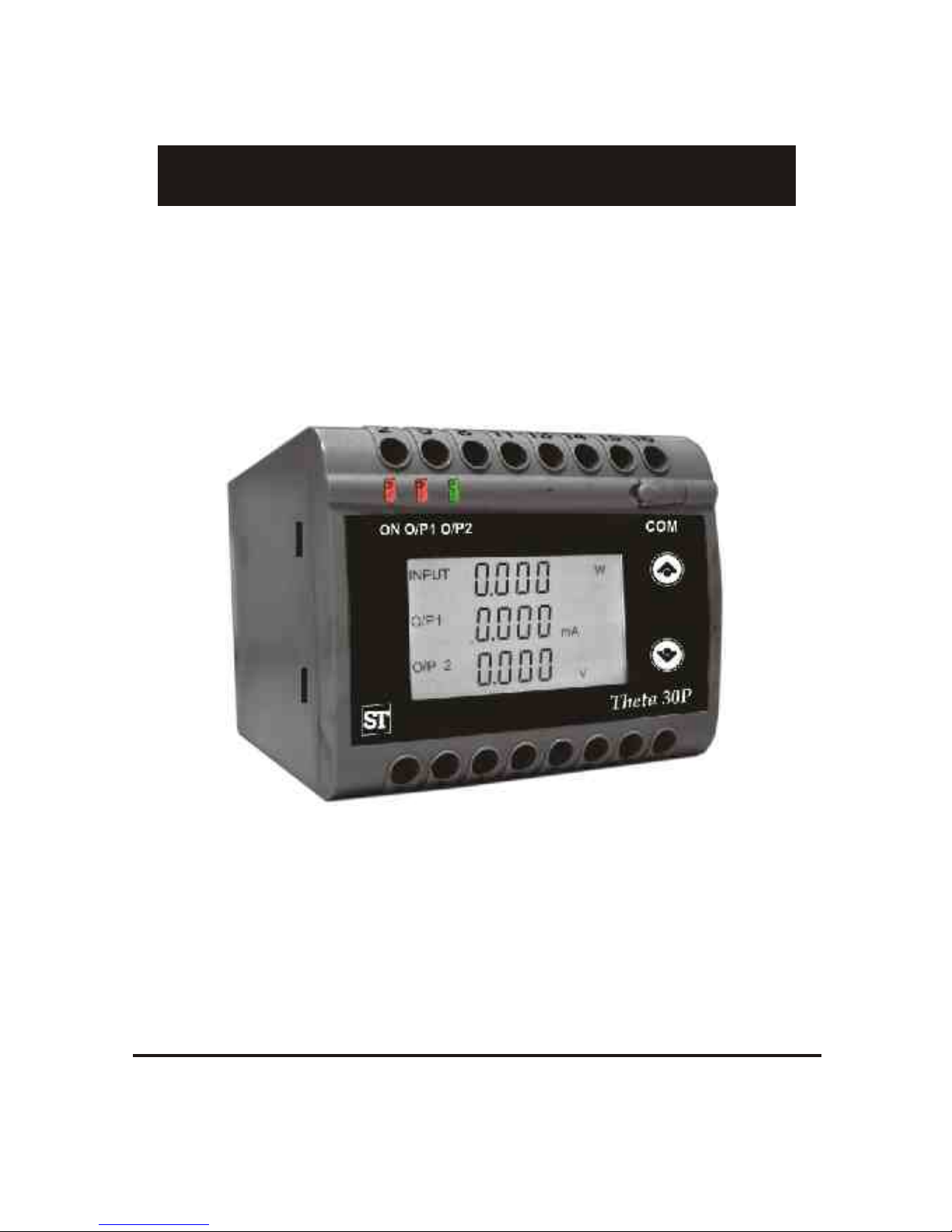
1. Introduction
The POWER/PHASE ANGLE/ POWER FACTOR TRANSDUCER is a DIN
The is used to measure and convert Active, Apparent, Reactive Transducer
Power, Phase Angle & Power Factor of a Single phase or Three phase AC
or voltage output signal.
System with balanced or unbalanced load into an proportional DC current
Transducer an be configured c
and programmed on site for the
The front panel has two push buttons through which the user can enter
into programming mode and can configure the transducer.
PT Primary ,PT Secondary,
CT Primary, CT Secondary, Input
Characteristics (i.e start, end
and elbow value of Input) and
Output Characteristics (i.e Voltage or Current and start, end and
6
following :
elbow Value of outputs.)
INPUTINPUT
O/P1O/P1
O/P 2O/P 2
VA VA
mA mA
V V
..
..
1.1: LED Indication
Green LED continuous ON
Aux. Supply healthy condition
ON
LED
LED OPERATING CONDITION
LED OPERATING STATUS
Output1 Voltage
Green LED continuous ON
O/P 1
Output1 Current
Red LED continuous ON
Output2 Voltage
Green LED continuous ON
O/P 2
Output2 Current
Red LED continuous ON
Rail/Wall mounted 78.5 X 65.5mm Transducer.
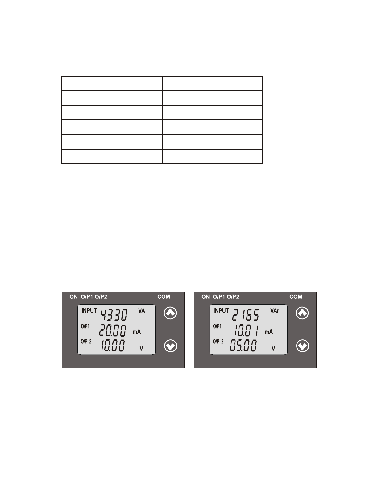
Table 1: Measured parameters
Measured parameters
Unit of Measurement
W
Active Power
Reactive Power
VAr
VA
Apparent Power
Power Factor
°(DEG)
Phase Angle
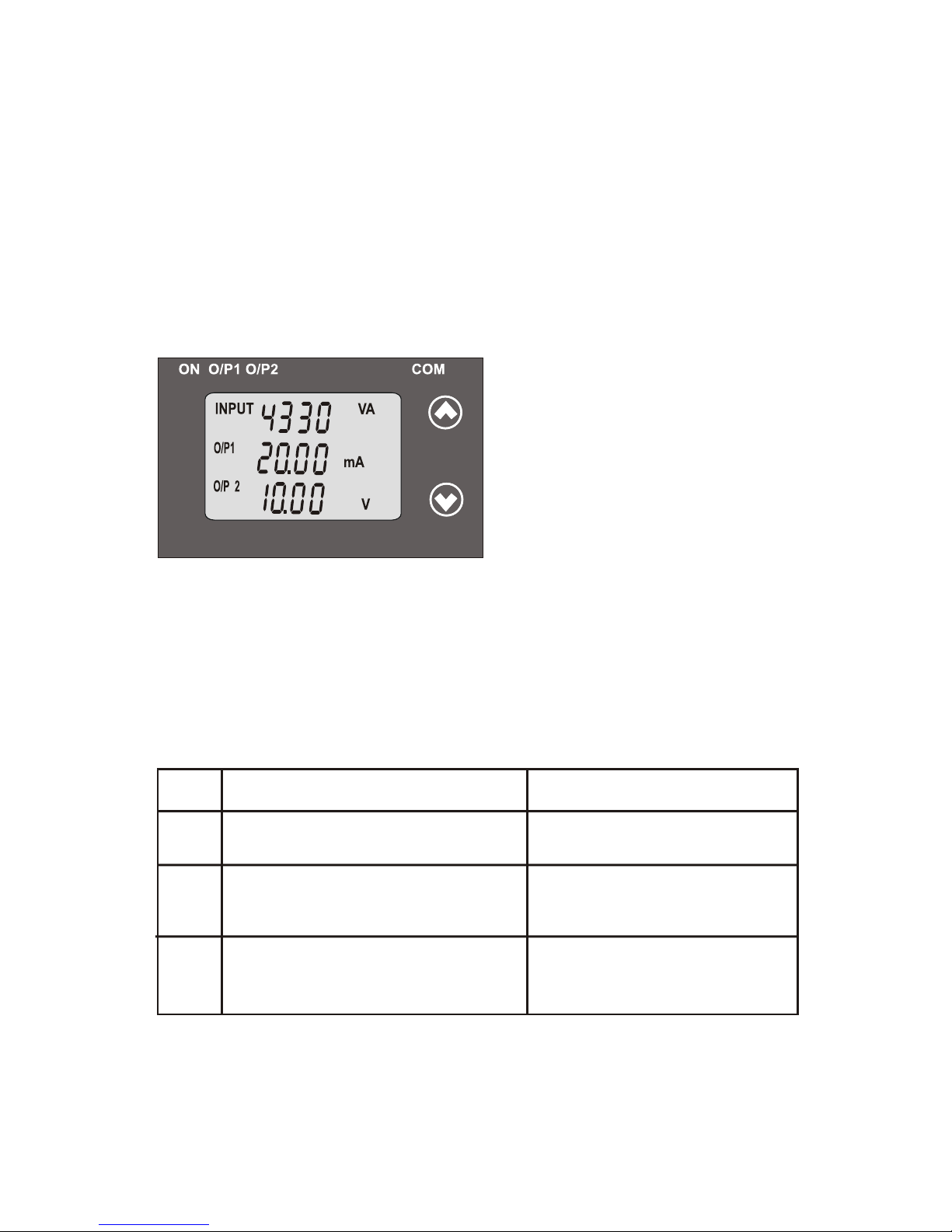
2 .
Input and Output screens
In normal operation the user is presented with display test screen
followed by version screen to one of the output screen.
7
Output 1 as Current or Voltage
For Reactive Power Transducer,
Output 1 as Current or Voltage
For Apparent Power Transducer :
Output 2 as Current or Voltage
Output 2 as Current or Voltage
–
Input Apparent Power,
Input Reactive Power,
INPUTINPUT
O/P1O/P1
O/P 2O/P 2
VA VA
mA mA
V V
..
..
INPUTINPUT
O/P1O/P1
O/P 2O/P 2
VAr VAr
mA mA
V V
..
..
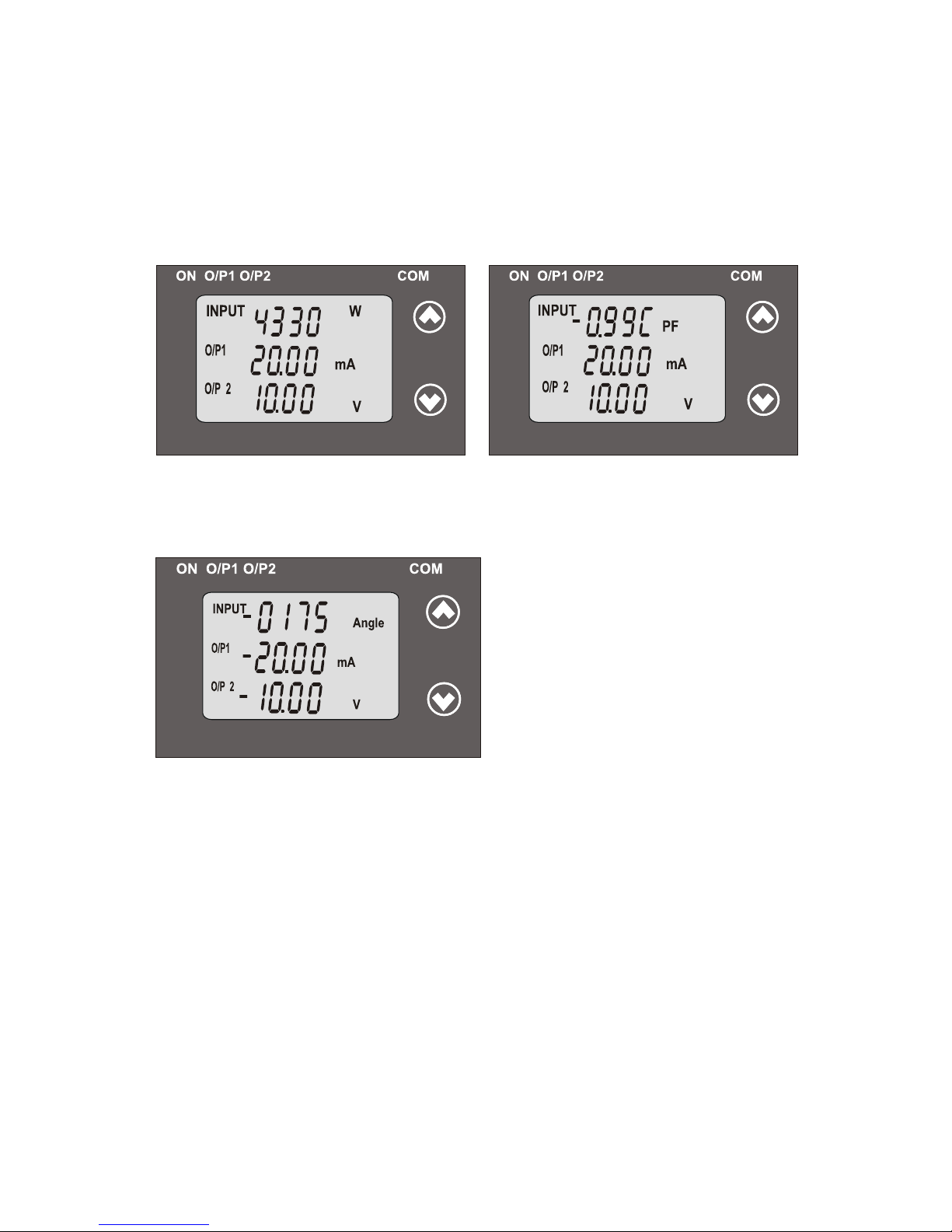
Output 1 as Current or Voltage
Input Active Power,
Output 2 as Current or Voltage
Output 1 as Current or Voltage
Input Power Factor,
Output 2 as Current or Voltage
Output 1 as Current or Voltage and Output 2 as Current or Voltage
For Phase Angle Transducer
3. Programming
Programming of transducer can be done in three ways :
3.1. Programming Via Front LCD & Two keys.
3.2. Programming Via Programming port available at front of
Transducers using optional PRKAB601 Adapter.
3.3. Programming Via optional RS485(MODBUS) communication port.
The following sections comprise step by step procedures for
configuring the Transducer for individual user requirements.
3.1: Programming Via Front LCD & Two keys
For Active Power Transducer,
For Power Factor Transducer
Input Phase Angle
INPUTINPUT
O/P1O/P1
O/P 2O/P 2
W W
mA mA
V V
..
..
--
..
..
..
INPUTINPUT
O/P1 O/P1
O/P 2O/P 2
PF PF
mA mA
V V
--
--
--
..
..
INPUTINPUT
O/P1 O/P1
O/P 2O/P 2
Angle Angle
mA mA
V V
8
*
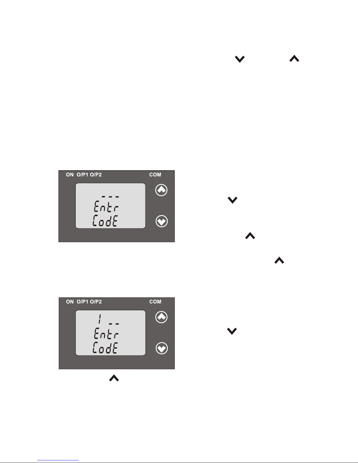
To access the set-up screens press and hold the “ Down” and “
Up” keys simultaneously for 5 seconds. This will take the User to
the password screen .
3.1.1: Password Protection:
Password protection can be enabled to prevent unauthorized access
to set-up screens, by default password protection is not enabled.
Password protection is enabled by selecting a four digit number other
than 0000. Setting a password of 0000 disables the password protection.
3.1.1.1: Password Verification
P ressing the “ Down” key will
Enter Password, prompt for first digit.
(*Denotes that digit will be flashing).
0 to 9 and the value will roll back again
to 0. Pressing the “ Up” key will
scroll the value of the first digit from
advance the operation to next digit and set the first digit.
9
In the special case where the Password is “0000” pressing the “ Up”
key when prompted for the First digit will advance to the “Password
Confirmation”mode.
*
After first digit gets entered, it will
prompt for second digit.
(*Denotes that digit will be flashing).
P ressing the “ Down” key will
from 0 to 9 and the value will roll
scroll the value of the second digit
Pressing the “ Up” key will advance the Operation to the next
digit and set the second digit.
back again to 0.
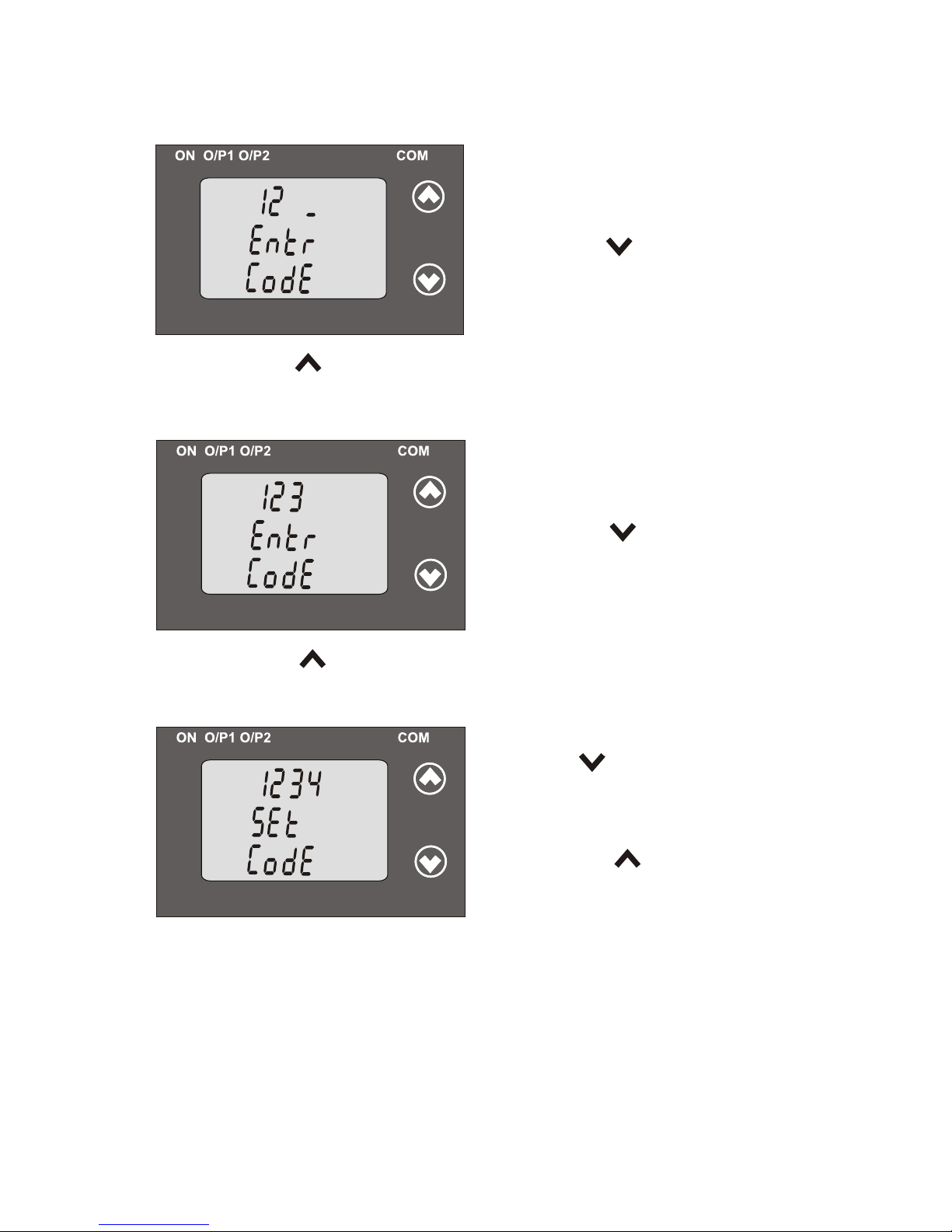
After, second digit gets entered, it
will prompt for third digit.
(*Denotes that digit will be flashing).
Pressing the “ Down” key will
scroll the alue of the third digit from v
0 to 9 and the value will roll back
Pressing the “ Up” key will advance the Operation to the next
digit and set the third digit.
*
*
After, third digit get entered, it will
prompt for fourth digit.
(*Denotes that digit will be flashing).
Pressing the “ Down” key will
scroll the alue of the fourth digit from v
0 to 9 and the value will roll back
again to 0.
Pressing the “ Up” key will advance the Operation to the next
10
Pressing “ Down” key will enter
to the “ Password edit ”
Confirmation of Password
advance to the Transducer Type
Pressing the “ Up” key will
mode .(section 3.1.1.2)
selection (section 3.1.2).
again to 0.
digit and set the fourth digit.

P s
o d Inco
rec .a
sw r
r t
uni
as t act h
n
o
ce
p
ted t
h
e P
as
s o
rw d
Pressing the “ Up” key will ex
t the
i setup menu.
Pre
sing he s
t
"
Down”
key
ll
wi
T is screen is d layed wh n
h
isp e
t
he
re-e
ter to
n the “Enter Pa sword” s
entry stage.
. 2
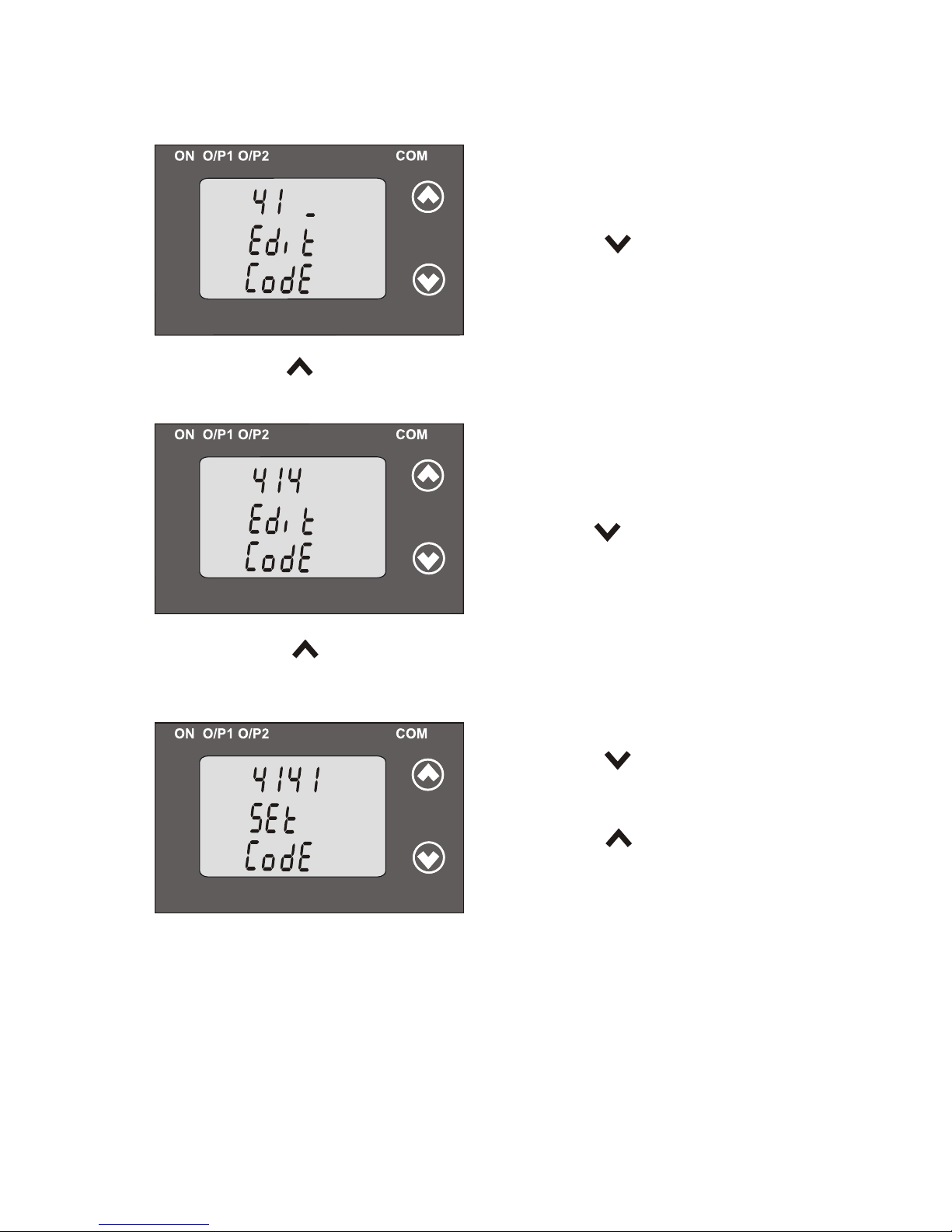
i g Ex
i
g Pa
s r3.1 1.
:
Edit n
ist
n
s
wo
d
U k
r
Pressing
the “
p”
ey will advance the ope ation to
e
i
th next d
git
an se th fir
dig
, in his case t
“
”d
t e st it t o
4
*
E
dEditing xisting Passwor
Pre
i g
he
Do
” y will
ss
n
t
“
wn ke
scr ll
th va
ue o th
o e
l f
e
fir t d
ig fr
m
s
it
o
e l
a
0 to 9 and th va
ue will roll b ck
(*
Den
ot
es
th
at d git will b
e fla
s ing
.i
h )
again to 0.
11
ess
n
” ey wi a
ance the ati n to
Pr
i
g the “
Up
k
ll
dv
oper
o the
t
next digi
d s
the
ec
d di s
c
1
an et s on
git, in thi ase to “ ”
*
A
ter
r
t
git gets enter
d, i
i
l
f fi s di
e t w l
r
f
or
om
p
p t eco
nd d
git
.
s
i
P
ess n “ own” k w ll
r
i g the D
ey
i
s
r
l the
alue of the
c o l v
econd d gi
s
i
t
fro to 9 and ue
ll oll
m 0
the val
wi r
(*Denotes that digit will be flashing).
back again to 0.
entered.
A te se
nd
ig
t
e en
r
d, f
r
co
d i
g
ts
te e it
will p t t ird digit h
.
rom
f rpo
P e
g e
Do ” k y will r
ssin th “ wn
e
s
cr
ll t
h
v
a ue o
th
o
e l
f e
th
d
dig
it f
om
ir r
0
t
o
9
a
n
va
e
w l
l
d
e
lu i
th o
l
l b ck
r a
Pressing
the
“
Up” key will advance the operation to
x
the ne t digit
d
s
and set the third igit, in thi case to “4”
*
(*Denotes that digit will be flashing).
e
g e U k
will a
an
t o er tio to
Pr
ssin
th
“
p” ey
dv
ce he
p
a
n he
a r
t “ P ss
wo
d
Confirm ” and set the f
urth digit,
oation
ode in this case to “1”.m
*
Afte th
d digit gets
nterer
ir
e
d
, it
l
wil
p
om
t
r p
r ou
th
ig
it
fo
f r
d .
Pre
in
g he
Do
wn”
k
ey w
ill
scro
ll ss
t “
th
va
ue of th
e l
e
fo
rt
digi fr
m u h t
o
0 o 9 and the value will roll back
t
(* Denotes that digit will be flashing).
again to 0.
12
Confirmation of Password
re-enter to the “ Password edit ”
to the Type Selection Transducer
Pressing the “ Up” key will
Pressing the “ Down” key will
confirm Password advance and
mode.
again to 0.
(section3.1.2).

3.1.2: Transducer Type Selection:
This screen allows the user to set the transducer type as Active,
Pressing “ Up” key will confirm the type
the System type selection(section 3.1.3).
selected and advance to
ACt : Active Power
APP : Apparent Power
rEA : Reactive Power
PF : Power Factor
PHA : Phase Angle
and will roll back again to ACt ( are flashing). Parameters
Pressing the “ Up” key will set the
Confirmation of Transducer Type
Pressing key will re-enter “ Down”
Transducer type and advance to the
INPUTINPUT
INPUTINPUT
Pressing the “ Down” key will show
“Transducer type edit” mode and scroll between
display
into “Transducer type edit” mode.
System type Selection (section 3.1.3).
Reactive, Apparent Power, Phase angle or Power Factor .
3.1.3: System Type Selection:
This screen allows the user to set System Type.
Pressing the “ Down” key will enter
into the “System Type edit” mode. For
Active / Apparent / Reactive Power
Transducer, System type will scroll
between
1PH2 : Single-Phase AC Network
3PH4 bAL : 3-Phase 4-Wire
balanced load
3PH3 bAL : 3-Phase 3-Wire balanced load
13
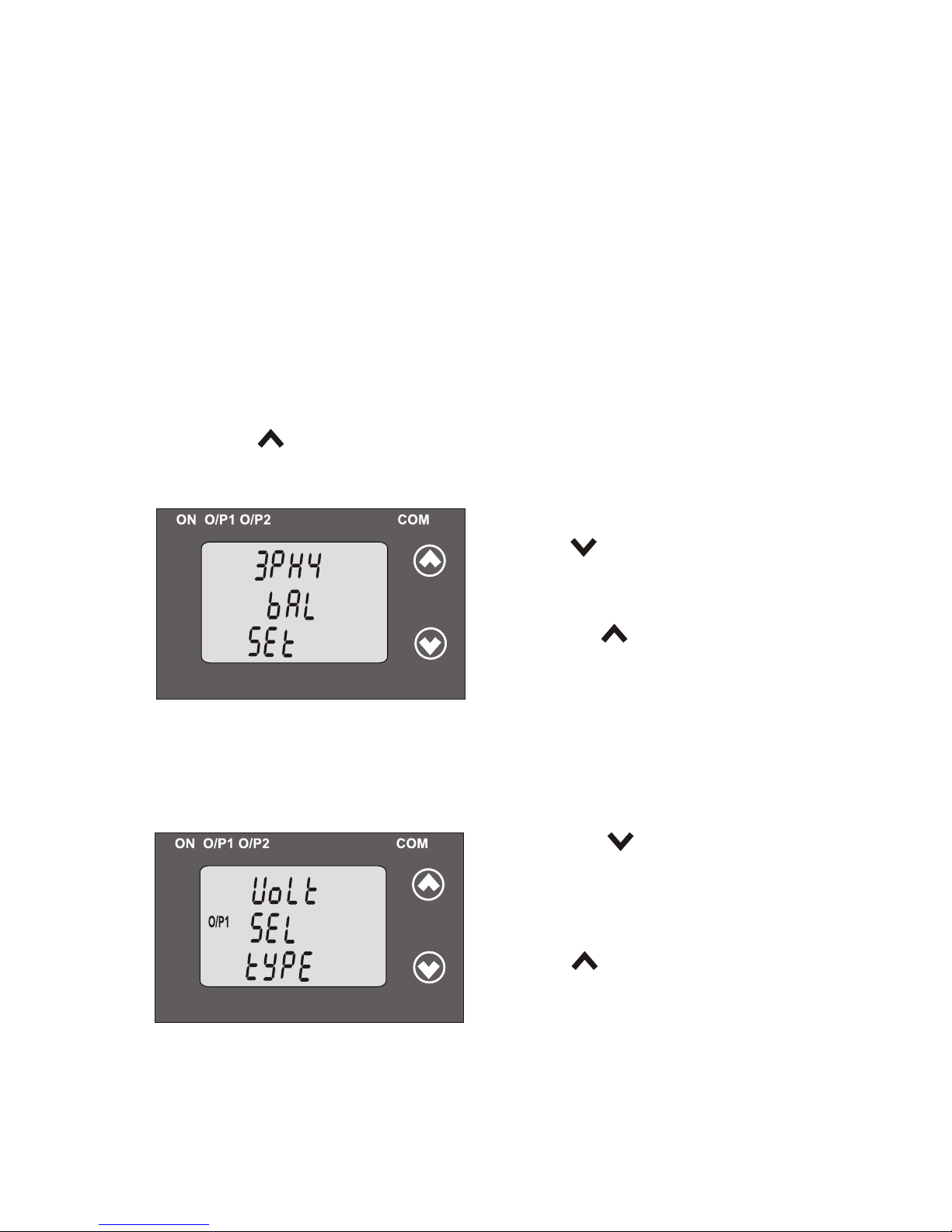
Pressing the “ Up” key will set the
value and advance to the Output
type selection (section 3.1.4).
Pressing “ Down” key will
re-enter into “System Type edit”
UL 12 bAL : 3-Phase 3-Wire balanced load
Pressing “ Up” key accepts the present value and advance to the
to the Output type selection (section 3.1.4).
UL 23 bAL : 3-Phase 3-Wire balanced load
UL 31 bAL : 3-Phase 3-Wire balanced load
3PH bAL : 3-Phase 4-Wire balanced load
3PH3 bAL : 3-Phase 3-Wire balanced load
1PH2 : Single-Phase AC Network
4
Confirmation of System Type
14
For Phase angle and Power factor Transducer networks supported are
3.1.4.: Output Type Selection:
This screen allows the user to set the output 1 type as Voltage or Current.
O/P1 O/P1
Pressing “ Up” key will confirm
the present type for Output 1 and
advance to the Output 2 type
selection(section 3.1.4.2).
Pressing the “ Down” key will
enter the transducer into “output 1
type edit” mode and scroll between
voltage and current.
3.1.4.1: Output 1 Type Selection
3PH3 UbAL : 3-Phase Unbalanced load3-Wire
3PH4 UbAL : 3-Phase 4-Wire Unbalanced load
mode.

O/P1 O/P1
Pressing the “ Up” key will set
the type and advance to the Output
2 type selection(section 3.1.4.2).
Confirmation of Output 1 Type
Pressing key will re-enter
into “Output 1 type edit” mode
“ Down”
.
3.1.4.2: Output 2 Type Selection
This screen allows the user to set the output 2 type as Voltage or
Current for dual output transducer.
Pressing “ Up” key accepts the
present type for Output 2 and
advance to the Potential Transformer
parameter selection(section 3.1.5).
Pressing the “ Down” key will enter
the “output 2 type edit” mode and
scroll between voltage and current.
O/P 2O/P 2
Confirmation of Output 2 Type
into “Output 2 type edit” mode.
Pressing the “ Up” key will set
the type and advance to the
Potential Transformer parameter
selection (section 3.1.5).
Pressing “ Down” key will re-enter
O/P 2O/P 2
Note: After changing Output type switch off the Transducer and
change DIP switch setting.If DIP switch setting is done before
changing the output Type through Display.Then change the Output
type through Display and switch off the Transducer and then
switch ON. (Section 3.3.1)
15
..
kV kV
*
3.1.5: Potential Transformer Parameter Setting:
This screen allows the user to set the PT Primary value from
Pressing “ Up” key will confirm
the present value as PT Primary
and advance to the PT secondary
value (Section 3.1.5.2).
Pressing the “ Down” key will
enter into the “PT Primary value
edit” mode.
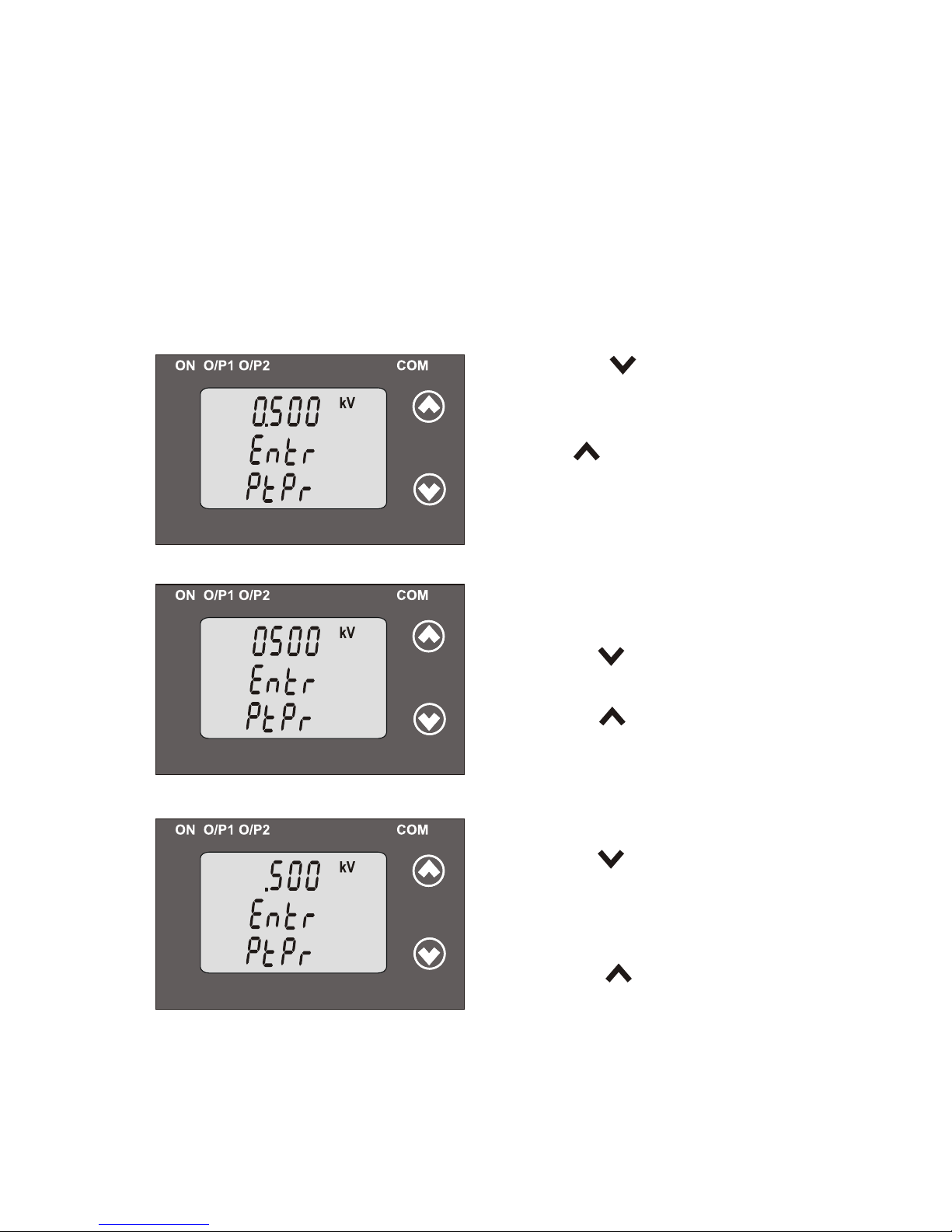
3.1.5.1: Potential Transformer primary value
..
kV kV
kV kV
*
Editing Existing PT Primary value
Pressing the “ Down” key will scroll
the decimal point to the next position.
Pressing the “ Up” key will confirm
the decimal point advance position and
(*Denotes that decimal point will be flashing).
the operation to set the first digit.
Pressing the “ Down” key will scroll
the value of the first digit from
0 to 9, and the value will roll back
advance the operation to the next
(*Denotes that digit will be flashing).
Pressing the “ Up” key will
16
100V to 692.8 KVL-L with consideration that presently written PT Primary
value with the previously set CT Primary value would not result in
maximum power of greater than 1000 MVA per phase.
again to 0.
digit and set the first digit, in this case to “0”.
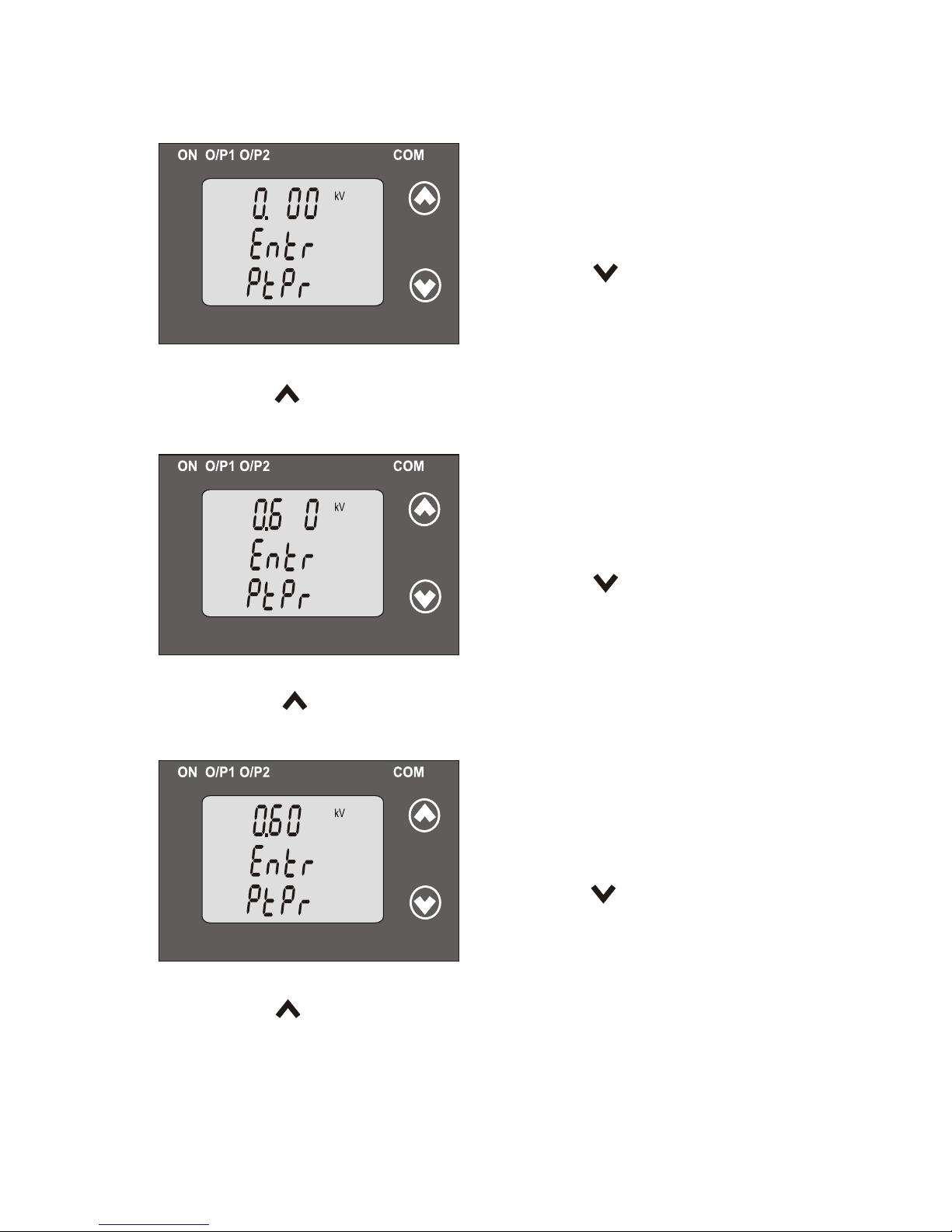
After ,first digit gets entered it will
Pressing the “ Down” key will scroll
the value of the second digit from
0 to 9 and the value will roll back
Pressing the “ Up” key will advance the operation to the next digit and
set the second digit, in this case to “6”.
promp fort second digit.
(*Denotes that digit will
After second digit gets entered, it will
promp fort third digit.
Pressing the “ Down” key will scroll
the value of the third digit from
0 to 9 and the value will roll back
Pressing the “ Up” key will advance the operation to the next digit and
set the third digit, in this case to “0”.
(*Denotes that digit will
..
kV kV
*
..
kV kV
*
..
kV kV
*
be flashing).
again to 0 or it will get restricted depending on first digit set.
be flashing).
(*Denotes that digit will be
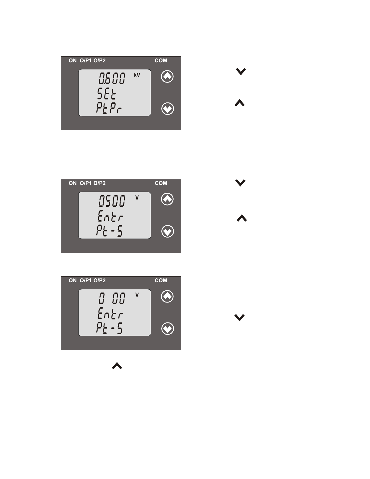
After third digit gets entered, it will
p for fourth digit.rompt
value confirmation in this case to “0”.” and set the fourth digit,
Pressing the “ Down” key will scroll
the value of the fourth digit from
0 to 9 and the value will roll back
Pressing the “ Up” key will advance the operation to the “PT Primary
flashing).
17
again to 0 or it will get restricted depending on third digit set.
again to 0 or it will get restricted depending on second digit set.
..
kV kV
Confirmation of PT Primary value
Pressing the “ Up” key will
confirm PT Primary value and
Pressing the “ Down” key will
re-enter to the PT Primary value edit ” “
This screen allows the user to set the PT Secondary value from 100 to 500VLL.
Pressing the “ Up” key will
confirm the present value as PT
Secondary and advance to the
Current Transformer Parameter
Setting (section 3.1.6).
Pressing the “ Down” key will
enter into the “PT Secondary value
edit” mode.
3.1.5.2 Potential Transformer Secondary Value
Editing Existing PT Secondary value
Pressing the “ Down” key will
scroll the value of the Second digit
from 1 to 5 and the value will roll
Pressing the “ Up” key will advance the operation to the next digit
and set the second digit, in this case to “3”
(*Denotes that digit will be flashing).
V V
V V
*
mode.
advance to the PT Secondary selection
back again to 1.
First Digit is always zero.
(section 3.1.5.2).
18
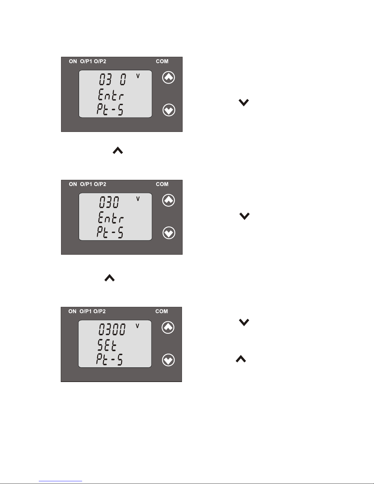
After third digit gets entered ,it will
(*Denotes that digit will be flashing)
Pressing the “ Down” key will
0 to 9 and the value will roll back
Pressing the “ Up” key will advance the operation to the next digit
and set the third digit, in this case to “0”.
will prompt for third digit.
*
V V
*
scroll the value of the third digit from
again to 0 or it will get restricted depending on second digit set.
(*Denotes that digit will be flashing)
Pressing the “ Down” key will
scroll the value of the fourth digit
from 0 to 9 and the value will roll back
Pressing the “ Up” key will advance to “PT secondary value confirmation”
mode digit, in this case to “0”.and set the fourth
V V
*
Confirmation of PT Secondary value
Pressing the “ Down” key will
re-enter into “PT Secondary value
Pressing the “ Up” key will
advance to the Current Transformer
confirm PT Secondary value and
V V
edit” mode.
19
After second digit gets entered ,it
prompt for fourth digit.
again to 0 or it will get restricted
depending on second digit set.
Parameter Selection(section 3.1.6).
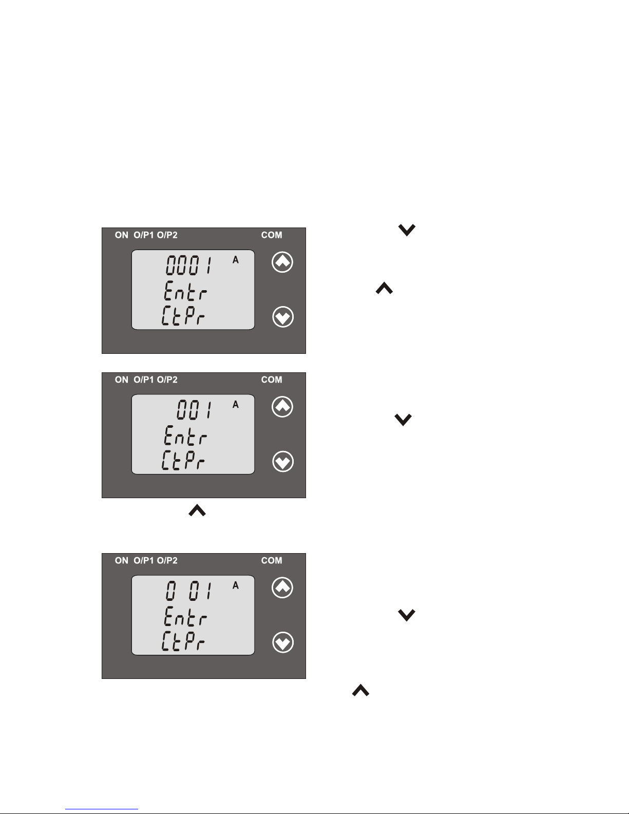
Editing Existing CT Primary Value
Pressing the “ Down” key will scroll
t first digit from he value of the
0 to 9 and the value will roll back
(*Denotes that digit will be flashing).
Pressing the “ Up” key will advance the operation to the next digit
and set the first digit, in this case to “0”
3.1.6: Current Transformer Parameter Setting
This screen allows the user to set the CT Primary value from 1 to 9999 A
Pressing “ Up” key will confirm
the present value as CT Primary
and advance to the CT secondary
selection (section 3.1.6.2).
Pressing the “ Down” key will
enter the transducer into “CT
Primary value edit” mode.
3.1.6.1: Current Transformer Primary Value
A A
*
A A
A A
*
prompt for second digit.
Pressing the “ Down” key will
scroll the value of the second digit
from 0 to 9 and the value will roll
depending on first digit set.Pressing the “ Up” key will advance the
operation to the next digit and set the second digit, in this case to “0”.
After, first digit gets entered, it will
again to 0.
(*Denotes that digit will be flashing).
back again to 0 or it will get restricted
with consideration that presently written CT Primary value with the
previously set PT Primary value would not result in maximum power of
greater than 1000 MVA per phase.
20
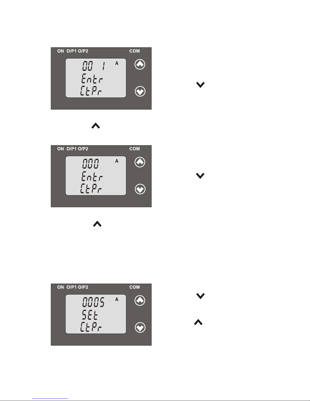
will prompt for third digit.
Pressing the “ Down” key will
scroll the value of the third digit from
0 to 9 and the value will roll back
Pressing the “ Up” key will advance the operation to the next digit
and set the third digit, in this case to “0”.
A A
*
After second digit entered, gets it
(*Denotes that digit will be flashing).
again to 0 or it will get restricted depending on second digit set.
A A
*
Pressing the “ Down” key will
scroll the value of the fourth digit
from 0 to 9 and the value will roll back
Pressing the “ Up” key will advance the operation to the “CT primary
value Confirmation ” and set the fourth digit, in this case to “5”.
After hird digit entered, t gets it will
prompt for fourth digit.
again to 0 or it will get restricted
Confirmation of CT Primary value .
Pressing the “ Down” key will
re-enter to the CT Primary value “
Pressing the “ Up” key will confirm
CT Primary value and advance
A A
edit” mode.
(section 3.1.6.2).
21
Example : If PT primary value is set as 692.8 KVL-L (Max value) then
to the CT secondary setting
CT primary Will restricted to 1736 A.The “Maximum power”restriction
of 1000 MVA refers to 120 % Nominal current & 120 % nominal voltage,
(*Denotes that digit will be flashing).
depending on third digit set.
i.e.694.4 MVA Nominal power per phase.
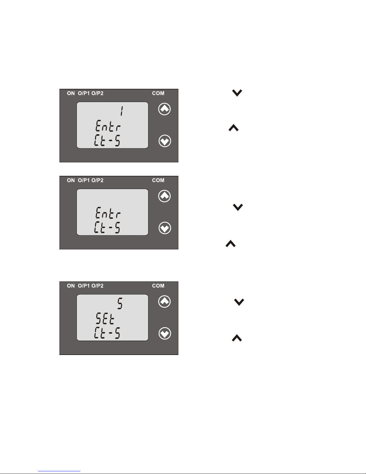
This screen allows the user to set the CT Secondary value from 1 to 5A.
Pressing the “ Up” key will confirm
the present value as CT Secondary
and advance to the Communication
Pressing the “ Down” key will
enter transducer into “CT
Secondary value edit” mode.
Editing Existing CT Secondary Value
Pressing the “ Down” key will
scroll the value 1 to 5 and value from
Pressing the “ Up” key advance will
the operation to the “ CT Secondary value confirmation”and set digit,
(*Denotes that digit will be flashing).
3.1.6.2: Current Transformer Secondary Value
*
parameter Setting (section 3.1.7).
Confirmation of CT Secondary Value
Pressing the “ Down” key will
return to the “CT Secondary
Pressing the “ Up” key will
confirm the CT Secondary advance and
value edit” mode.
(section 3.1.7).
to the Communication parameter Selection
22
will roll back again to 1.
in this case to “5”.
*
*
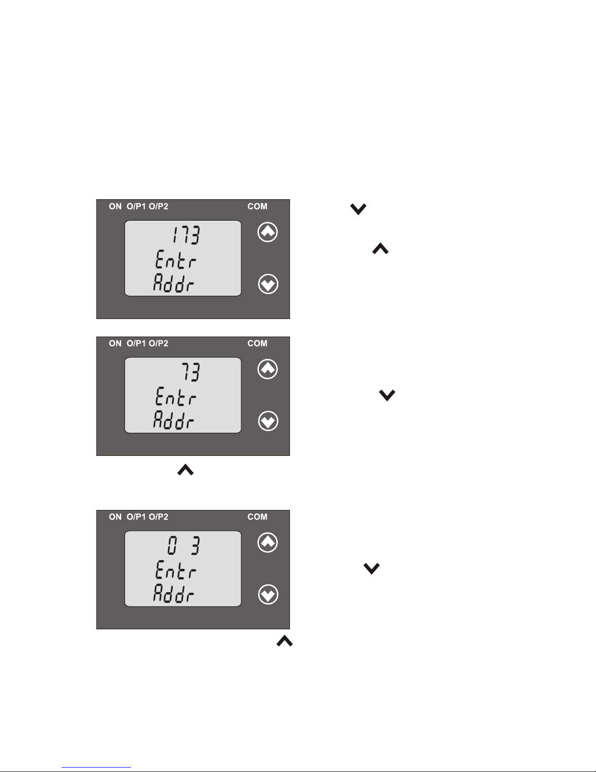
3.1.7.1 Address Setting
This screen applies to the RS 485 output only.
This screen allows the user to set RS485 parameter for instruments.
The range of address is 1 to 247.allowable
3.1.7: Communication Parameter Setting:
Pressing “ Down” key will advance
to the “ edit” mode.address value
Pressing the “ Up” key will confirm
the present value as address and
advance to Baud Rate selection
(section3.1.7.2).
(*Denotes that digit will be flashing).
Pressing the “ Down” key will
scroll the value of the second digit
from 0 to 2 and the value will roll
Pressing the “ Up” key will advance the operation to the next digit
and set the second digit, in this case to “0”.
Editing Existing Address Value
First digit is always blank.
back again to 0.
After, second digit gets entered, it will
(*Denotes that digit will be flashing).
Pressing the “ Down” key will scroll the
value of the third digit from 0 to 9 and
the value will roll back again to 0 or
second digit set. Pressing the “ Up” key will advance the operation
prompt for third digit.
to the next digit and set the third digit, in this case to “0”.
23
it will get restricted depending on

After gets it will third digit entered,
Pressing the “ Down” key will scroll
the value of the fourth digit from 0
to 9 and the value will roll back
Pressing the “ Up” key will advance the operation to the “ Address
depending on third digit set.
Confirmation of Address Value
Pressing the “ Down” key will
re-enter to the Address value edit” “
Pressing the “ Up” key will confirm
Address value and advance to
*
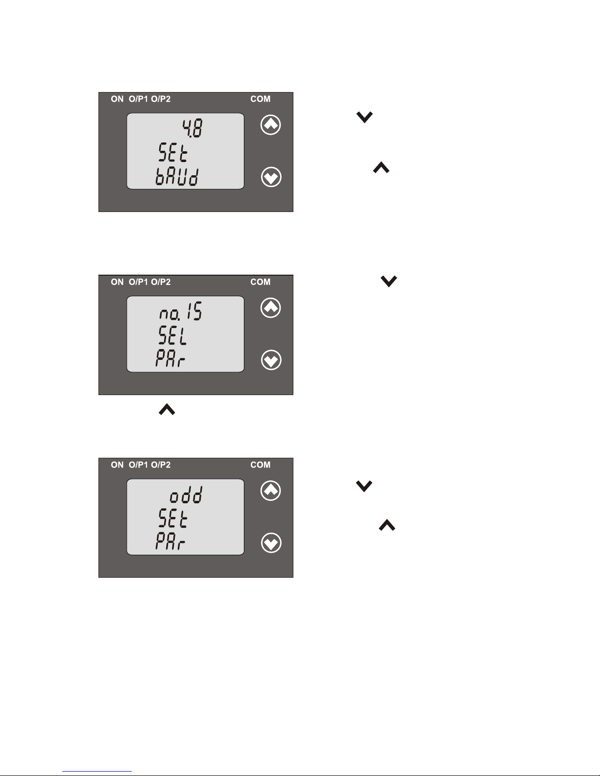
3.1.7.2: RS 485 Baud rate
This screen allows the user to set Baud
Rate of RS 485 port. The values
Pressing “ Up” key the present value
advance to the RS485 Parity Selection(section 3.1.7.3).
will confirm as Baud rate and
Pressing the “ Down” key will enter
into the “Baud Rate edit” mode and
scroll the value between 2.4, 4.8, 9.6 ,
19.2 and value will roll back again to
2.4(values are flashing).
..
prompt for fourth digit.
again to 0 or it will get restricted
mode.
Baud Rate selection (section3.1.7.2) .
displayed on screen are in kbaud .
24
(* denotes that digit will be flashing).
value confirmation”mode and set the fourth digit, in this case to “1”.
Confirmation of RS 485 Baud Rate
Pressing key will re-enter “ Down”
Pressing the “ Up” key will
the Baud rate value and advance to
confirm
into the “Baud Rate edit” mode.
..
the Parity Selection (section 3.1.7.3).
3.1.7.3: RS 485 Parity Selection
This screen allows the user to set Parity & number of stop bits of RS 485 port.
Pressing the “ Down” key will
enter into the “Parity & stop bit edit”
mode and scroll the value between
odd : odd parity with one stop bit
no. 1S : no parity with one stop bit
no. 2S : no parity with two stop bit
EVEn : even parity with one stop bit
Pressing “ Up” key accepts the present value and
Input Characteristics selection(section 3.1.8).
advance to the
..
Pressing the “ Up” key will set
Confirmation of RS 485 Parity
Pressing key will be “ Down”
the value and advance to the Input
re-enter into “Parity edit” mode.
Characteristics selection
25
(section 3.1.8).
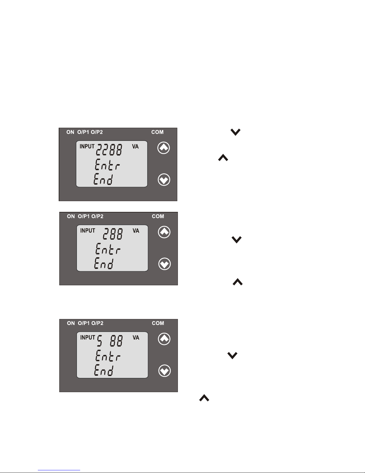
Pressing “ Up” key will confirm the
present value as Input End value
and advance to the Start value of
Input (section 3.1.8.2).
Pressing the “ Down” key will enter
into “Input End value edit” mode.
INPUTINPUT
VA VA
Editing Existing Input End value
Pressing the “ Down” key will
scroll the value of the first digit from
0 to 5 the value will and roll back again
Pressing the “ Up” key will
advance the operation to the first digit, in this the next digit and set
(*Denotes that digit will be flashing).
INPUTINPUT
VA VA
*
After first digit gets entered, it will
(*Denotes that digit will be flashing).
Pressing the “ Down” key will scroll
the value of the second digit from
0 to 9, and the value will roll back
on the value of first digit. Pressing the “ Up” key will advance the
operation to the next digit and set the second digit, in this case to “0”.
INPUTINPUT
VA VA
*
prompt for second digit.
again to 0 or get restricted depending
26
3.1.8: Input Characteristics Setting
3.1.8.1: End value of Input
This screen allows the user to set the End value of Input with respect
to system type & Transducer type. Allowable range of End value is
30% to 130% of Rated power.(Consider that we have Selected the
Input as Apparent Power.)
to 0.
case to “5”.
 Loading...