

Sifam Tinsley Omega Xmer 10, Omega Xmer 20, Omega 3 Phase Operating Manual
Multifunction Meters
Transducers & Isolators
Temperature Controllers
Converters & Recorders
Digital Panel Meters
Current Transformers
Analogue Panel Meters
Shunts
Digital Multimeters
Clamp Meters
Insulation Testers
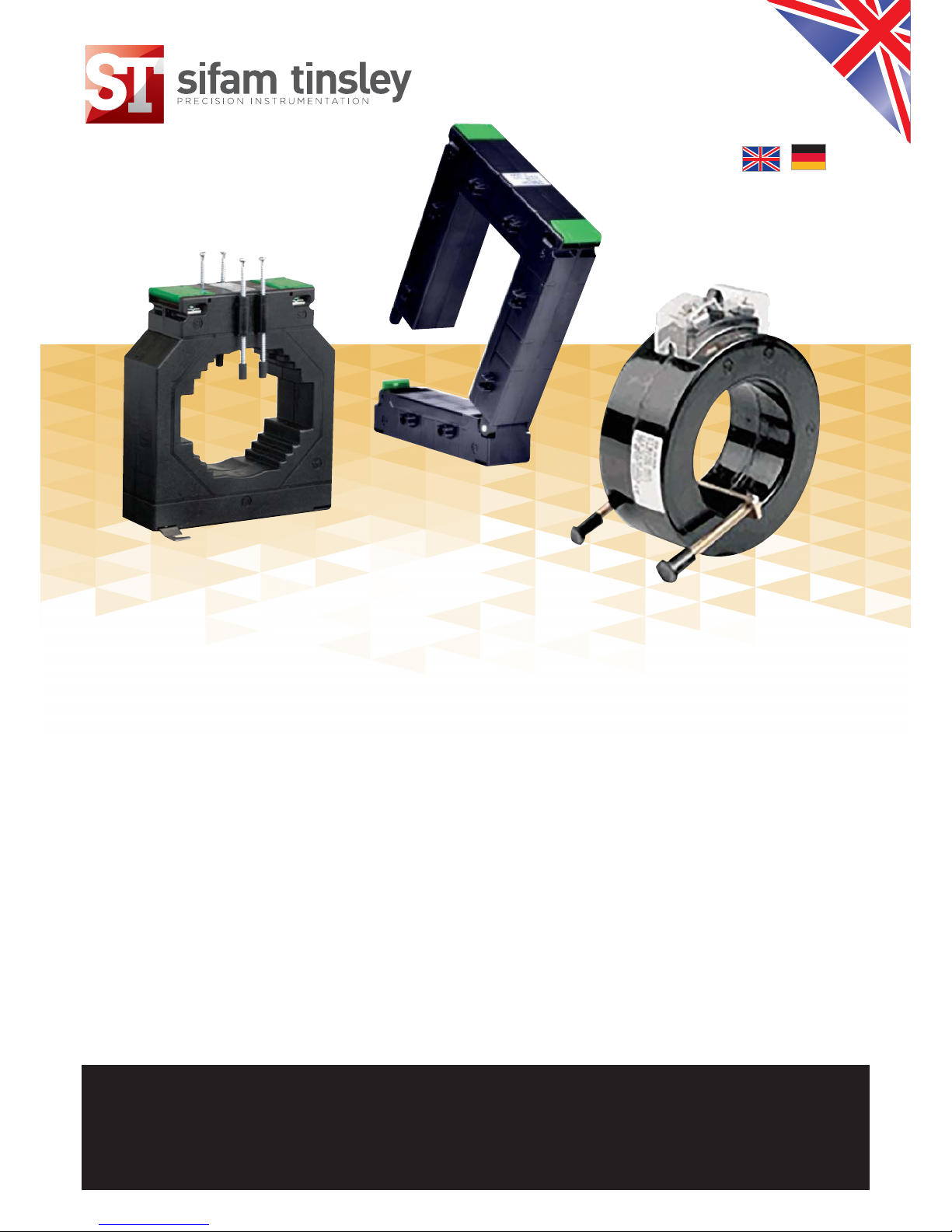
TRANSFORMER SERIES
OMEGA XMER, 10 & 20
NIEDERSPANNUNGSSTROMWANDLER
BAUREIHE OMEGA XMER, 10 & 20
Operating Manual - Issue 2.0
Bedienungsanleitung – Ausgabe 2.0
SUBJECT TO CHANGE WITHOUT NOTICE
This manual superseded all previous versions – please keep for future reference
ÄNDERUNGEN VORBEHALTEN
Dieses Handbuch ersetzt alle vorherigen Versionen – Bitte aufbewahren
TRANSFORMER SERIES
NIEDERSPANNUNGSSTROMWANDLER, BAUREIHE:
Omega XMER, Omega 10, Omega 20
www.sifamtinsley.co.uk
OMEGA XMER, OMEGA 10, OMEGA 20
TRANSFORMER SERIES
CT Operating Datasheet
Issue 2.0
Indication
Before initial operation we ask to you pay full attention to these assembling instructions in order to
guarantee the reliability and to ensure the performance of the device.
Functional Description
Current transformers of the model range Omega are inductive single conductor-current
transformers operating according to the transformer principle. Due to the applicated measuring
principle, current transformers of this type may only be installed in alternating current (AC)
networks.
Safety Instructions
TRANSFORMER SERIES
Features
➜
Low voltage Current Transformer
➜
Omega Xmer Series
➜
Omega 10 Series
➜
Omega 20 Series
In order to avoid personal and material damage the following assembling steps must
be performed only by authorised, qualified and trained personnel.
If the secondary circuit is operated without a burden/load (open) high-voltages may
appear. These voltage values are dangerous for persons as well as for the functional
reliability of the current transformer. It is forbidden to operate the current
transformer without a secondary circuit (open)!
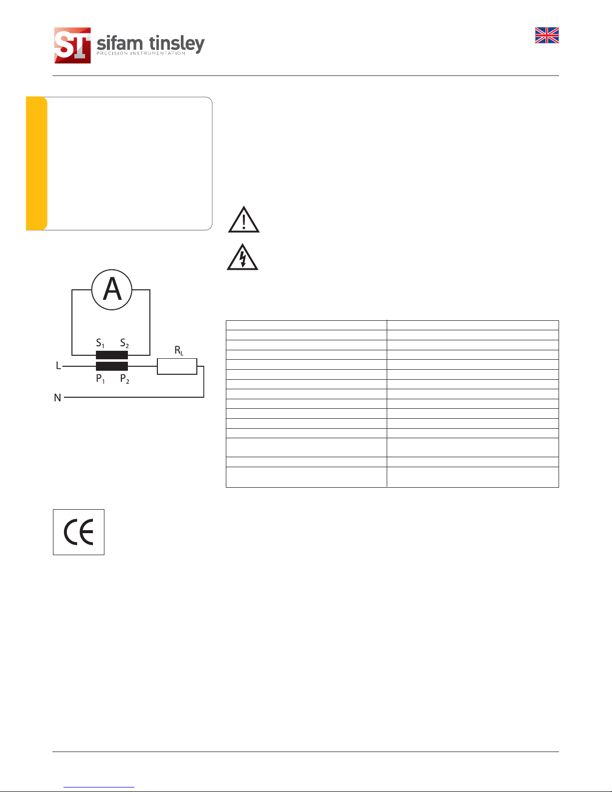
Technical Parameters
Primary current 5A to 6000A
Secondary current 1A or 5A
Accuracy class 0.2, 0.2s, 0.5s & 1
Over current limiting factor FS5, FS10, FS15
Rated frequency 50Hz or 60Hz
Rated continuous thermal current (standard) 1,2 x in
Rated short time thermal current lth 60 x in, 1 s (Max 40kA)
Rated isolation level 0.72/3 kV or 0.72/4 kV
Place of insulation Indoor
Altitude up to 2000 m
Degree of protection IP20
Degree of pollution 2
Ambient temperature -5°C to + 55°C
(0-95% relative humidity, non condensing!)
Storage temperature -25°C to + 70°C
Applied standards IEC 60044-1 / IEC 61869-1 : Performance
IEC - 61010 - 2 : Safety
Assembly
1. Ensure a safe work environment during assembly, maintenance and inspection operations. If
necessary interrupt the current supply of the primary conductor and take precautions against
unintentional switching.
2 (i) For Split Core CT : Open the current transformer and fix it on the primary conductor using the
fixing clamps (mounting material).
(ii) For Window type CT : Bar or cable primary insert through primary cable or bus bar & fix it using
mounting screw assembly.
P1: Direction of power supply
P2: Direction of power source
Attention:
(i) For Split Core CT Do not close the current transformer, high voltages may appear on the open
secondary leads.
(ii) Check the cleanness of the cut surfaces of the split core.
3. Connect the secondary wires of the current transformer with the measuring device (ampere meter,
energy meter). Pay attention to the installation guide of the measuring device.
4. Now fasten the current transformer, press until the lock engage.
5. If necessary, start the current supply again.
6. Check whether the current transformer is assembled correctly and the secondary leads are
connected properly.
7. For split core CT, use ‘lock pin’ supplied along with CT to protect accidential opening of CT,
during use.
Wiring Diagram
Contact Us
Environmental Instruction
When the product has reached it’s ‘end of life’, it
must be recycled. Pass it to an electrical waste
disposal. Do not dispose as unsorted municipal
waste!
This product was developed
and manufactured in
accordance with applicable
regulations (IEC61010,
IEC61869) and meets the
requirements of the low
voltage guideline
2014/35/EU.
Sifam Tinsley Instrumentation Ltd
1 Warner Drive
Springwood Industrial Estate
Braintree, Essex
CM7 2YW
Tel: 01376 335271
E-mail: sales@sifamtinsley.com
www.sifamtinsley.co.uk
 Loading...