

Page 1
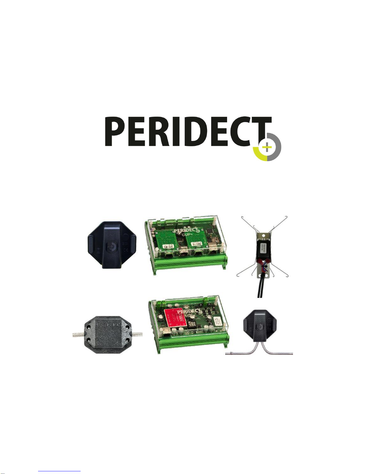
Perimeter Detection System - Installation manual
The manual describes installation and configuration of the PERIDECT+ detection system and is
intended exclusively for authorized partners of the manufacturer SIEZA, a.s.
Updated: 02/11/2016
Page 2

- 1 -
Contents
1.
Introduction – basic description of PERIDECT+ ..................................................... - 2 -
1.1. Purpose of the System .............................................................................. - 2 -
1.2. System Topology ...................................................................................... - 2 -
2. HW of the PERIDECT+ System ................................................................................. - 3 -
2.1. PERIDECT+ Detection Line ................................................................ ...... - 3 -
2.1.1. Standard Version ................................................................................ - 4 -
2.1.2. Antivandal Version .............................................................................. - 5 -
2.1.3. Hidden Version ................................ ................................................... - 6 -
2.1.4. Installing the Perimeter onto the Fence ............................................... - 7 -
2.2. CUP+ – Control Unit PERIDECT+ ............................................................. - 9 -
2.2.1. Connecting the CUP+ Terminal Board .............................................. - 10 -
2.3. LCP+ – Line Controller PERIDECT+ ....................................................... - 12 -
2.3.1. Connecting the LCP+ Terminal Board ............................................... - 12 -
2.3.2. LED Signalling of CUP+ and LCP+ ................................................... - 13 -
2.4. LIP+ – Line Input PERIDECT+ ................................................................ - 13 -
2.5. LPP+ – Line Protection PERIDECT+ ...................................................... - 13 -
2.6. IOP+/LAN/RS485 I/O Module PERIDECT+ ............................................. - 14 -
2.6.1. Connecting the IOP+ Terminal Board ............................................... - 14 -
2.7. LSP+ – Line Separator PERIDECT+ ....................................................... - 15 -
2.8. Block Diagram of the System .................................................................. - 15 -
3. Technical Specification of PERIDECT+ .................................................................. - 16 -
3.1. PERIDECT+ CUP+ Control Unit.............................................................. - 16 -
3.2. PERIDECT+ LCP+ Line Controller .......................................................... - 16 -
3.3. PERIDECT+ LIP+ Line Input ................................................................... - 16 -
3.4. PERIDECT+ DSP+ Detection Sensor ..................................................... - 16 -
3.5. PERIDECT+ LSP+ Line Separator .......................................................... - 16 -
3.6. PERIDECT+ IOP+/LAN I/O Module ........................................................ - 17 -
3.7. PERIDECT+ IOP+/RS485 I/O RS485 Module ......................................... - 17 -
3.8. PERIDECT+ IOP+/EXP I/O Expansion Module ....................................... - 17 -
Page 3

- 2 -
1.
Introduction – basic description of PERIDECT+
1.1. Purpose of the System
The PERIDECT+ perimeter detection system is intended especially for protection against
trespassing into the secured area or property. The system can be fitted onto common fence types
(such as traditional mesh fences, welded mesh in rolls, welded fence segments, fence
superstructure), as well as non-standard fence types (metal board fences, decorative welded fences).
Apart from the standard version, they are also made in more resilient design (the Antivandal version).
They can also be installed inside poles of fence frames (the Hidden version). There are even more
options available, such as a detector of the manipulation with photo-voltaic panels or combinations
with various types of mechanical inhibition.
PERIDECT+ detects vibrations generated by mechanical stimulus that accompanies the
trespassing attempts (climbing, cutting or crawling under the fence).
PERIDECT utilizes the so-called "differential logic" which significantly reduces false alarms
caused by weather conditions (rain, wind, hail, lightning bolts) and enables operation under these
conditions without need to manually or automatically adjust the system sensitivity settings.
1.2. System Topology
The system consists of basic components:
CUP+ control unit
LCP+ line controller
DSP+ detection sensor
The system can be supplemented by additional elements according to the specific application:
LIP+ line input (double input module)
LPP+ line protection (overvoltage protection module)
IOP+/LAN I/O LAN module (relay module with ETH interface)
IOP+/RS485 I/O RS485 module (relay module with RS485 interface)
LSP+ line separator
IOP+/EXP 16 relay expansion module connectable to both IOP+/LAN and
IOP+/RS485 modules
The detection is carried out by DSP+ detectors mechanically attached to the fence at the rate
of one detector per one fence segment. The detectors contain a piezoelectric sensor with
microprocessor signal processing. Each detector has its own address assigned within
a detection line connected to one line module, which allows setting parameters of each detector
individually. The accuracy of intrusion point detection when using PERIDECT+ is therefore per one
DSP+ sensor.
Page 4
- 3 -
The DSP+ detectors are connected to each other in parallel configuration, as well as to the
line module.
It is possible to connect up to 500 addresses to one LCP+ line module. These addresses can
be used by a combination of DSP+ or LIP+ modules.
LIP+ module provides two double-balanced inputs, whose states are distinguished by different
values of balancing resistance for each input. These inputs allow connecting a different security
device to the PERIDECT+ system (magnetic contact, IR or MW barrier etc.). LPP+ overvoltage
protection module is installed on the line in order to increase the overvoltage resistance of the
system. It is also possible to fit the line with insulator modules which allow for automatic
disconnection of a specific part of the line that is experiencing technical problems in form of a lead in,
a short circuit etc. Their fitting is especially appropriate for installations of circular or continuous
connection design.
Being the core of the system, CUP+ unit is fitted with several auxiliary module ports. Directly
on the CUP+ board, there are four OC outputs which can be configured freely. The number of
outputs can also be expanded by IOP+/LAN
or IOP+/RS485 modules via ETH and RS485 ports. These modules are equipped with relay outputs
and can be used to connect the PERIDECT+ system outputs to inputs of equipment made by other
manufacturers (security central, DVR etc.) while maintaining the galvanic separation of these
systems.
PERIDECT+ acts as a fully autonomous alarm system and its programmable outputs can be
connected to common security centrals just like standard sensors. In this case, the detector groups
are usually combined within the appropriate outputs and the system detects alarm situations based
on individual, freely defined zones.
2. HW of the PERIDECT+ System
2.1. PERIDECT+ Detection Line
The detection line of the PERIDECT+ perimeter detection system consists of DSP+ detectors
interconnected by a twin core cable. This cable is used as a power supply, as well as a digital data
transfer line between the detectors and the evaluation unit.
The detection lines are made in three versions: Standard, Antivandal and Hidden. This
corresponds with the designation marking of the detection lines (for ordering purposes):
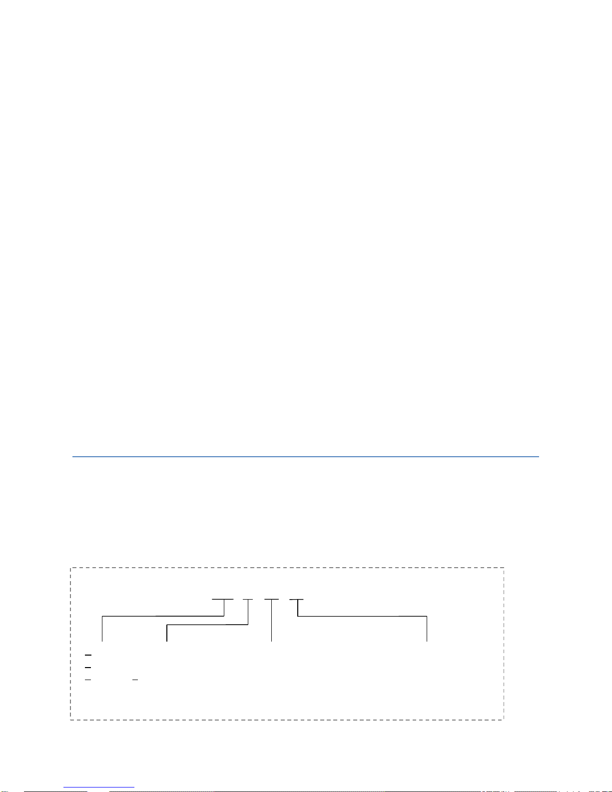
DSP+ / X / YY / ZZ
Detection
Sensor
PERIDECT+
Version:
S – Standard
A – Antivandal
H – Hidden
Posts spacing in decimetres
(for Standard and Antivandal)
Version:
B – Basic
Page 5
- 4 -
DSP+ contains a sensor fitted in a protective casing. This sensor detects mechanical shocks
of the fence via piezoelectric converters. The shocks are digitised, pre-processed by the sensor's
microprocessor and delivered using digital sub transfer to the LCP+ module for further processing
and finally to the CUP+ evaluation unit.
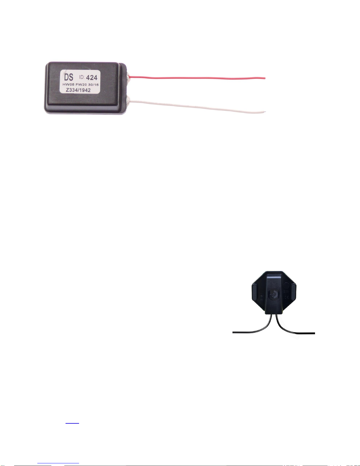
PERIDECT+ detection sensor
Marking of the PERIDECT+ detection sensor on the picture:
DS – type of detection sensor
ID : 424 – Sensor address (1 – 500)
30/15 – production date (week number and year)
Z334 – internal marking
1942 – internal marking
FW20 – firmware version
HW05 – hardware version
2.1.1. Standard Version
A basic detection perimeter version. The Standard version
currently uses the same casing design as the Antivandal version.
The detection sensor is placed in the detector casing that acts as a
"roof" and therefore has to be installed using a cover with two
screws that always point towards the ground.
The detectors are connected using a special twin-core cable
of exterior design, i.e. a cable with coating resistant to UV radiation
and outside environment.
The Standard version of detection perimeter always comes with pre-connected detectors.
When ordering
a detection line, it is necessary to define the posts spacing (a direct distance between the centre of
one post to the centre of another). In case the pole spacing varies, the longest distance is used. This
is used as a measure for cables in production, with an installation addition of approximately 40 cm
added for turns at the detector and around the post.
For reasons of weight and dimensions of the detectors, the Standard version detection lines
come in packages of maximum of 100 interconnected detectors. The delivered segments are
connected at the installation site to make a complete perimeter. A detailed installation is described in
chapter 2.1.4.
Page 6
- 5 -
2.1.2. Antivandal Version
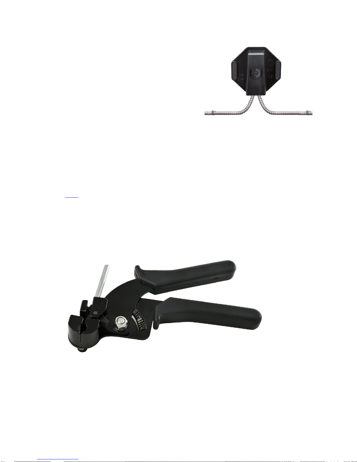
This version features increased resistance to cable
damage, e.g. being cut by the intruder or bitten apart by
animals. The twin core cable is positioned in a stainless
steel protection tube that secures the mechanical
protection of the cable. The protection tube can also act
as shielding in places with high-intensity electromagnetic
interference (such as direct exposure to radar radiation).
Like the Standard version, the Antivandal version
of detection line always comes with connected detectors.
When ordering a detection line, it is necessary to define the posts spacing (a direct distance between
the centre of one pole to the centre of another). In case the posts spacing varies, the longest
distance is used. This is used as a measure for cables in production, with an installation addition of
approximately 40 cm added for turns at the detector and around the post.
For reasons of weight and dimensions of the detectors, the Antivandal version detection lines
come in packages of maximum of 50 interconnected detectors. The delivered segments are
connected at the installation site to make a complete perimeter. A detailed installation is described in
chapter 2.1.4.
Positioning of the sensors on the fence and connecting the perimeter segments is similar to
the Standard version.
KE1128-C stainless steel tapes are used when installing the cables in the protection tube onto
the fence. The tapes are attached using the M100 mounting pliers which are also equipped with a
cutting device.
Prior to fixing using the stainless steel straps, it is recommended to fix the detection line cable
with standard plastic fixing ties, followed by the steel ties.
Page 7
- 6 -
2.1.3. Hidden Version
The Hidden version is designed for situations where it is necessary that the fence cannot be
identified as security-protected. The detectors are installed inside the posts. Interconnecting cables in
the protector are also led through the posts and underground in between the posts (alternatively on
the foundation wall or the fence frame).
Installation of this solution is more demanding and the Hidden version does not come with
interconnected detectors. The protectors with cables leading from one post to another have to be
prepared prior to the installation. This can be done for new fences during their installation, but can
turn out to be problematic for existing fences.
In some cases, a solution can be used for existing fences where the detectors are placed
inside the poles and the cable is fitted on top of the fence. While the cables are not protected from
potential damage anymore, they are not as noticeable and therefore less conspicuous (depends on
the fence type and installation method).
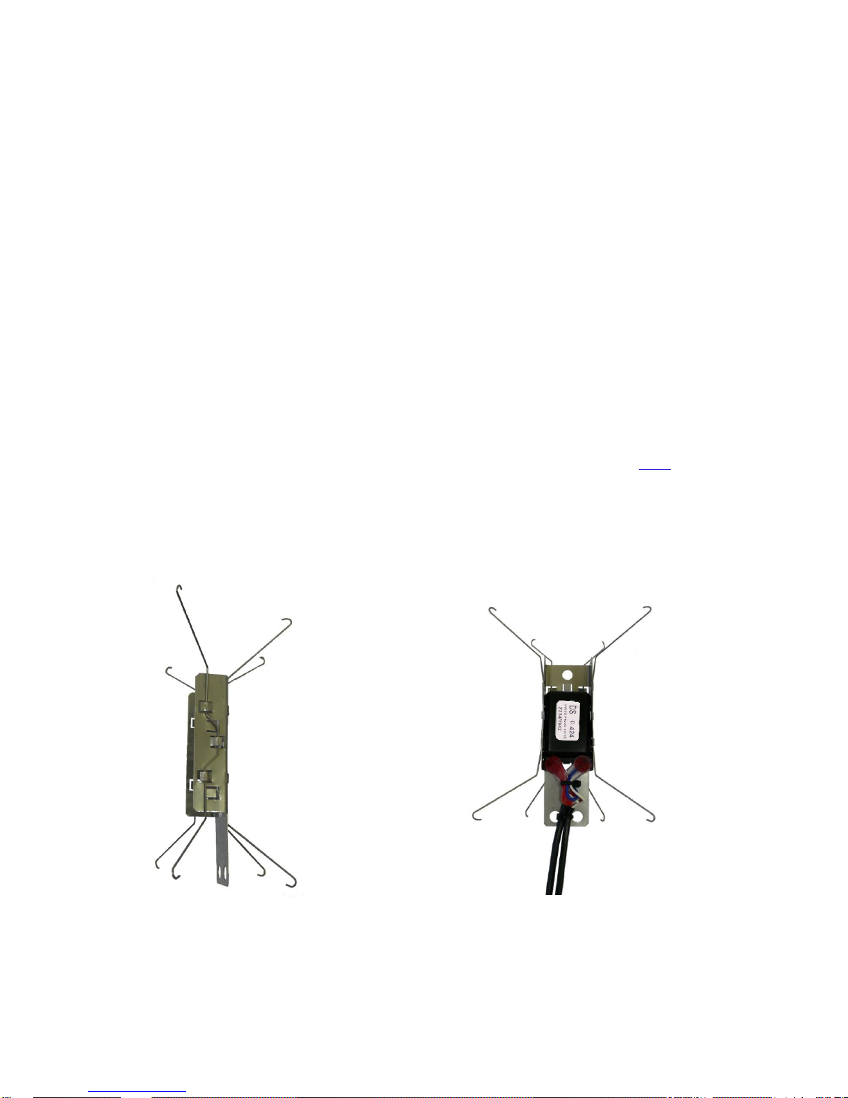
In order to be able to be placed inside posts of different shapes and diameters, the detection
sensor itself is attached to a sheet metal holder with springs (the so-called "bridge") that ensures its
fixation inside the post. Sometimes it is appropriate to fasten the sensor holder (e.g. using an Sshaped wire – there is a hole in the holder for this purpose), so that it does not sink deeper inside the
post over time. Additionally, a blind flange has to be used to enclose the hole in the pole so that the
detector is protected from rain.
During installation, the cables are connected using UR2 gel couplings (see 2.1.4 connecting
the line). The cable is secured against pulling out by fixing to the detection sensor holder using a
binding strap at the bottom of the holder (there are two more holes for this purpose). There is a
shaped shim on the other side of the holder which is bent to secure the detector from shifting. The
third hole at the top is used to manipulate the holder inside the pole. We can provide an appropriate
tool with a hook at the end that can be used to manipulate the detector inside the poles.
Detector holder for the Hidden version Connection and securing of hidden detector cable
Page 8
- 7 -
2.1.4. Installing the Line on the Fence
For the installation it is necessary to plan preliminary the detectors addressing as per the
disposition of the object to be secured. The detectors are delivered with the addresses already in the
lines with the maximum number of the detectors in one line according to the version of the product.
The first and the last detector of the line have the ID number (address) stuck on the lid of the
detector´s casing. ID number of each detector from the production can be found out also inside the
casing from the detector´s description.
After placement the detectors are installed on the fence and the line is fastened. Afterwards it
is necessary to connect the delivered sections into the detection line.
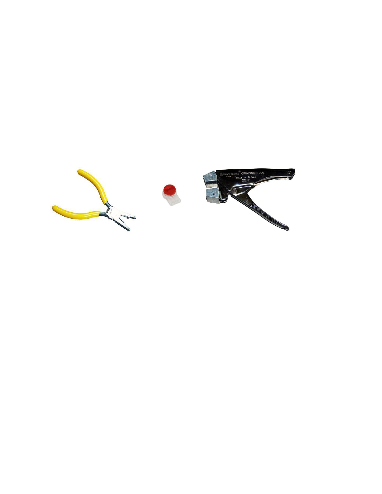
Single sections are connected by means of the gel connectors UR2 inside the protection
cover of the end detectors. For the reliable execution of the connection we totally recommended to
use only the special jaw crimping tool E-9Y or E9BM type.
E-9Y pliers, Scotchlok UR2 gel coupling and E-9BM pliers
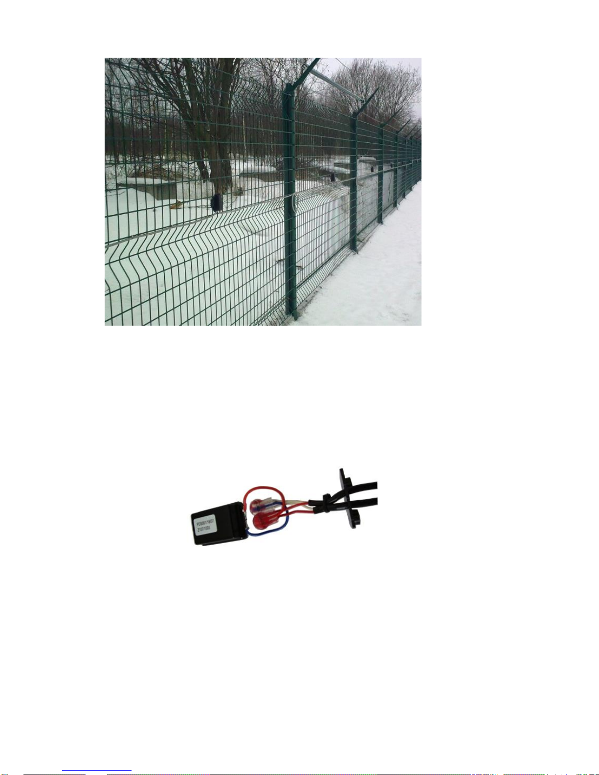
The detector itself is fixed on the fence by four screws by means of the fastening clamp
(totally 8 holes are prepared for the screws to be able to choose the most suitable openings in
accordance with the type and execution of the fence). The detector is always placed in the middle of
the single fence panel outside the tensioning wires of the fence. The cable is fixed to the fencing by
the fastening ties after approximately each 25 cm (10 pcs. fastening ties between each two
detectors) to avoid the impacts of the wiring to the fencing caused by the wind in order to reduce the
probability of causing the false alarms.
Before connecting the line the outside black insulation is removed and inside wires including
the coloured working insulation are inserted into the openings of the UR2 gel connector. One
connector is used for the connection of red conductors, the second connector for the connection of
the white conductors (or as the case may be with the blue one). The wires of the detector are
inserted into the middle opening of the UR2 connector, the conductors of the cable into the side
ones. We recommend swapping of detector’s polarity periodically (e.g. swapping connection from
red-red -> red-white and white-white -> white-red). Pressing by the jaw crimping tool E-9Y/E-9BM
makes the connection of the conductors. Superfluous gel pushed out of the connector is removed
and the visual check of the connection is executed. Correctly made connection has the red surface
completely pressed parallel with the connector edge and all three conductors inserted inside the
connector as to the stop.
Note: before connecting the lines in Standard version it is necessary to pass both cables through the
bottom lid of the cover. Check the right position of the lid (smooth surface upwards, please see the
picture 2)
Page 9
- 8 -
Detector placement and the method of running the cables across the fence
Inner arrangement of the detector
Page 10
- 9 -
2.2. CUP+ – Control Unit PERIDECT+
The control unit processes the signals acquired from individual LCP+ line modules to which all
DSP+ and LIP+ modules are connected. It evaluates the events of the individual detectors based on
an internal algorithm and subsequently controls related actions, inputs switching, camera control and
sending data into the SW superstructures.
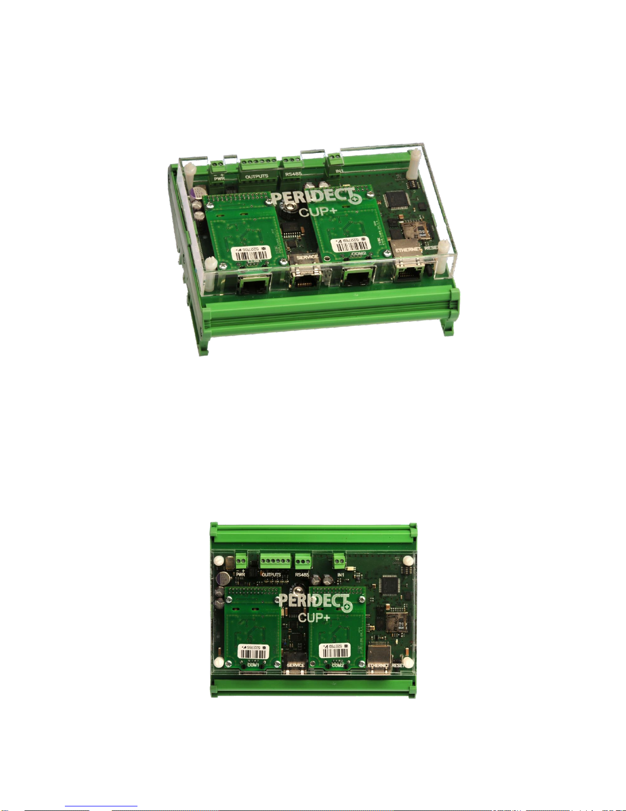
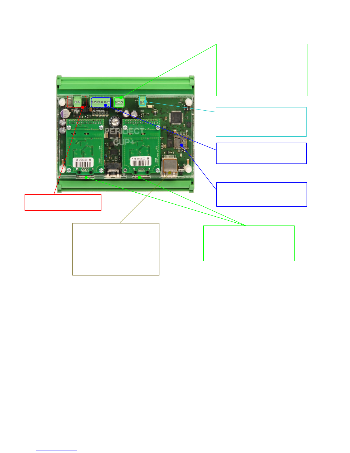
The CUP+ control unit is equipped with several external control and communication modules.
There are OC-type outputs which are freely programmable and can be used for purposes such as
basic system status indication. The outputs use semi-conductor switches. It is not recommended to
use higher switching voltage than that used to power the CUP+ unit or current consumption
exceeding 250 mA.
The evaluation unit is placed inside a plastic casing suitable for installation on a DIN rail. For
exterior environment, it has to be provided with appropriate IP protection.
CUP+ Control Unit
CUP+ top view
Page 11
- 10 -
2.2.1. Connecting the CUP+ Terminal Board
Terminal board – output connection,
utilizes the shared terminal connection
RS 485 data line – brought out at two
places in parallel: As a system
connector for service interventions
and onto the terminal board with
screwed terminals for permanent
installation. Just one line may be
connected at a time.
Tamper terminal board – connection
of external protective contact (tamper)
from the assembly box or another
cover, NC contact
Supply terminal board – supply
voltage of 9 – 16 VDC
ETH connector – for connecting
CUP+ to the data network,
communicating with other elements
in the data network, communication
with other network elements,
IOP/LAN, cameras using the Onvif
protocol
RS 232 data line – used for connection
of the LCP modules, it is possible to
use standard UTP patchcord
Micro SD slot – memory card slot for
purposes of saving logs, configuration
etc.
Page 12
- 11 -
0V +Uc 1 2 3 4 5 6 0V + -
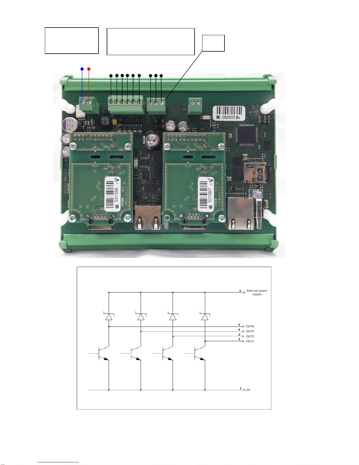
Schematic internal connection of CUP+’s outputs and their assignment to connectors
UC – power voltage
9 – 16V DC
Output terminals, for detailed
connection see picture below
RS485
Page 13
- 12 -
2.3. LCP+ – Line Controller PERIDECT+
LCP+ line controller creates a communication interface for all line modules. This line is used
for both powering and communication of the modules. The communication is carried out based on
the principle of regular query where LCP+ receives information from individual modules of the line to
process them and send the results to the CUP+ control unit using the RS232 serial interface.
2.3.1. Connecting the LCP+ Terminal Board
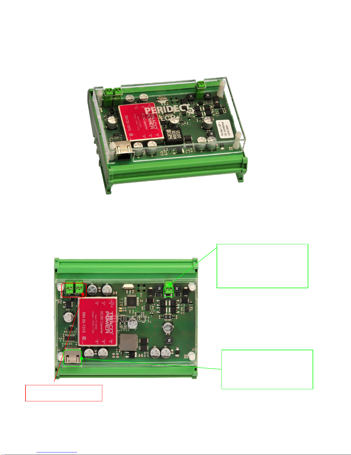
LCP+ Line Controller
Supply terminal board – supply
voltage of 9 – 16 VDC
RS232 connector – used for
connection and communication with
the CUP+ control unit. It’s possible to
use standard UTP patchcord.
Data line – used for connection and
communication with all line types of
the modules. The bus has no polarity,
meaning the modules can be wired in
any way.
Page 14
- 13 -
2.3.2. LED Signalling of CUP+ and LCP+
Flashing yellow led on the CUP+ indicates the processor is running and all the internal
processes of the unit are operating properly.
Flashing green led on the LCP+ indicates the processor is running and all the internal
processes of the module are operating properly.
Flashing red LED on the LCP+ module indicates communication via the RS232 bus. It also
flashes during the query period when communicating with the CUP+ unit. After turning the power
supply on, both LEDs of the LCP+ module light up simultaneously for 2 seconds. This brief operation
mode is intended for service purposes.
2.4. LIP+ – Line Input PERIDECT+
The input module is used for connecting an external device
positioned on the detection perimeter.
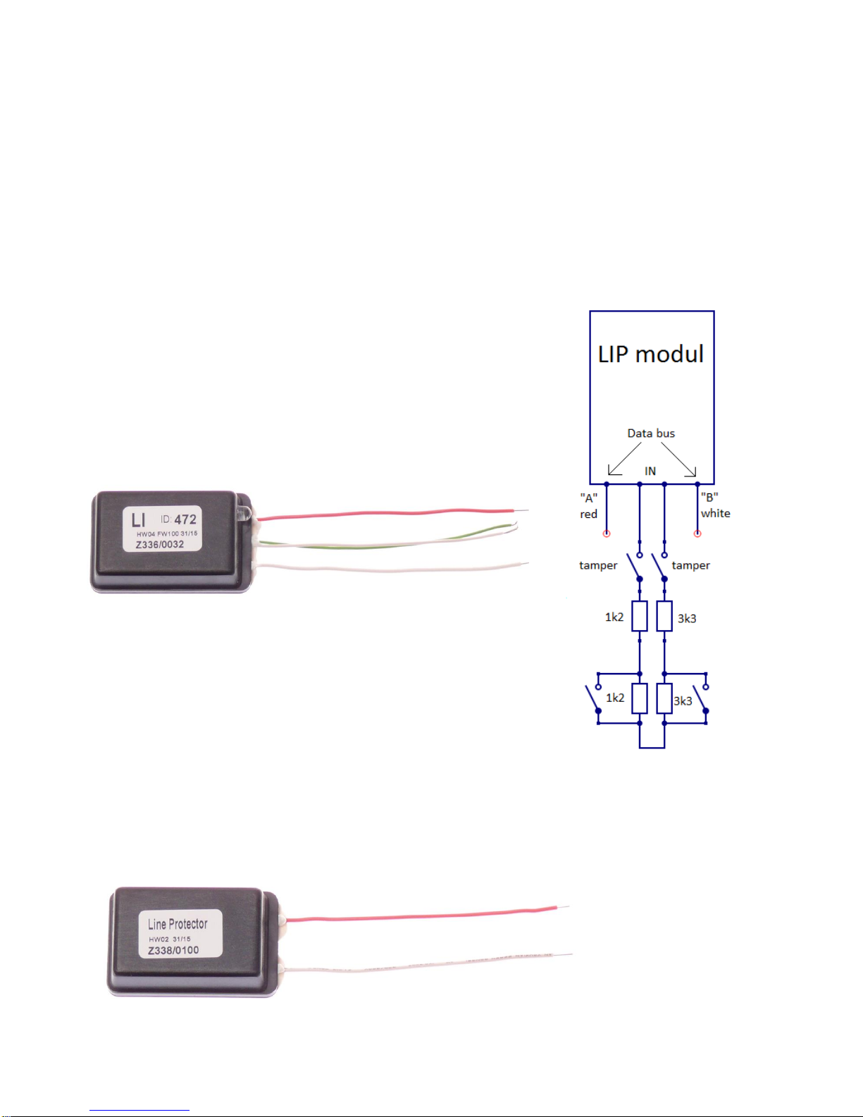
The LIP+ module has two double-balanced inputs (the first
input is equipped with balancing resistors of 2 x 1.2 kΩ, the
second one is fitted with 2 x 3k3 resistors). They are connected
parallel to the detection line at any point of its length. The
identification of the LIP+ module is defined using its address.
In practice, the input can be used for devices such as a magnetic
contact at the gate used to indicate whenever it is opened. Other
examples include an IR gate or a microwave barrier above the
gate or in the perimeter area that cannot be protected by fence.
2.5. LPP+ – Line Protection PERIDECT+
LPP+ overvoltage protection looks like a standard detector and uses the same casing. It is
used to increase the resistance to electromagnetic field and surge peaks such as those caused by
lightning bolts. It contains
a set of elements that
limit the potential voltage
interference peak
between the conductors
of the bus.
LPP+ Overvoltage Protection Module
LIP+ module Schematic
drawing of inputs connection
Page 15
- 14 -
The overvoltage module should be installed in regular span along the whole detection line. A
detection line of maximum length should be fitted with 15–25 modules.
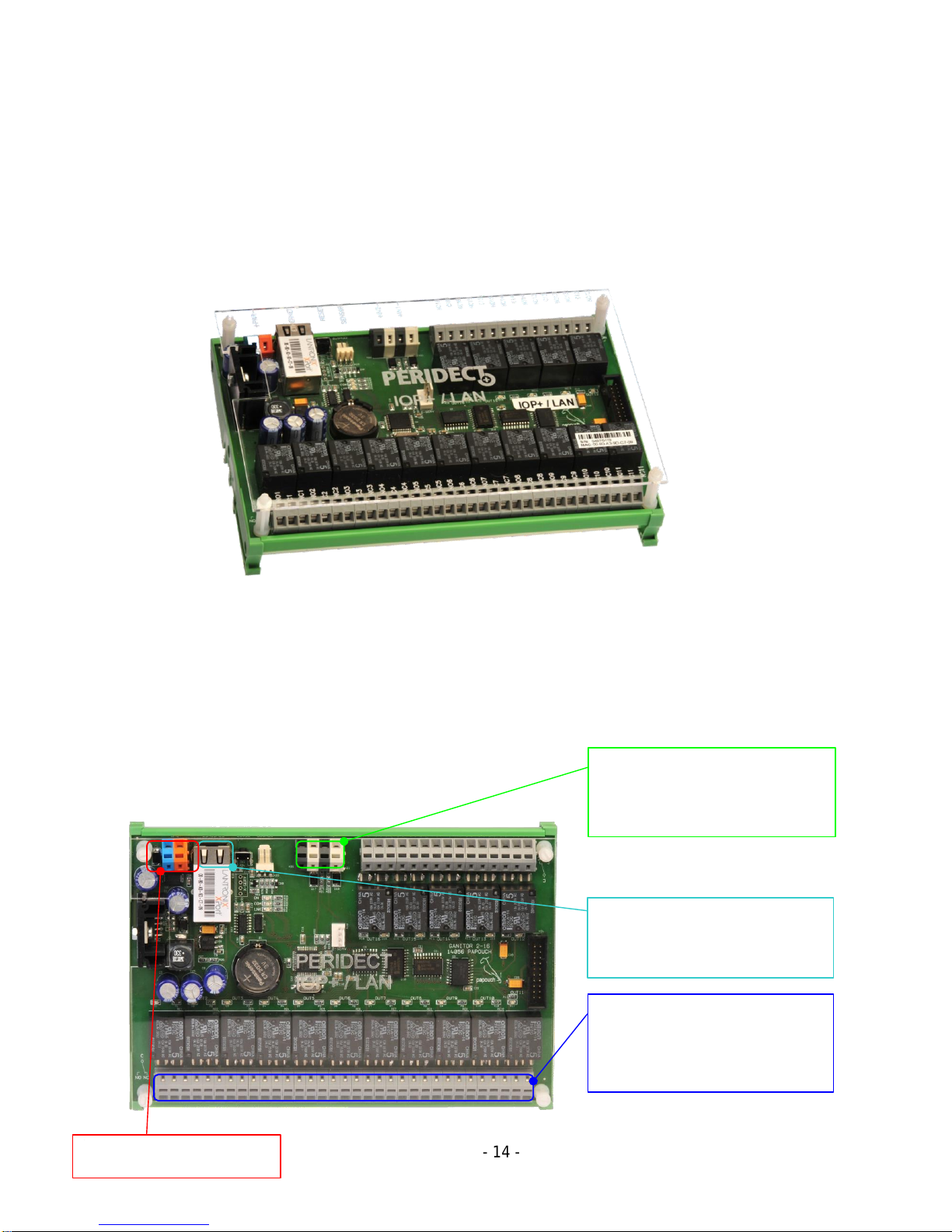
2.6. The IOP+/LAN/RS485 I/O Module of PERIDECT+
An output module used to control external devices, as well as indicate malfunction or alarm
statuses. The evaluation unit sends commands via the RS485 or ETH interface, depending on the
design of the output module. Each module is also provided with a couple of balanced inputs. Those
can be used to connect external devices such as magnetic contacts, motion detectors etc.
The output module is placed inside a plastic casing suitable for installation on a DIN rail. For outside
environment, it has to be provided with appropriate IP protection.
2.6.1. Connecting the IOP+ Terminal Board
Terminal board – used to connect the
outputs; complete switching contact is
brought out for each relay. Relay
outputs are in order : NO,C,NC
Input terminal board – can be used to
connect external auxiliary devices. The
inputs are double-balanced.
Supply terminal board – supply
voltage of 9 – 16 VDC
ETH/RS485 connector– interface used
to connect to the CUP+ control unit.
Either the RS485 or the Ethernet is
used, depending on the module type.
IOP+ Output Module
Page 16
- 15 -
2.7. LSP+ – Line Separator PERIDECT+
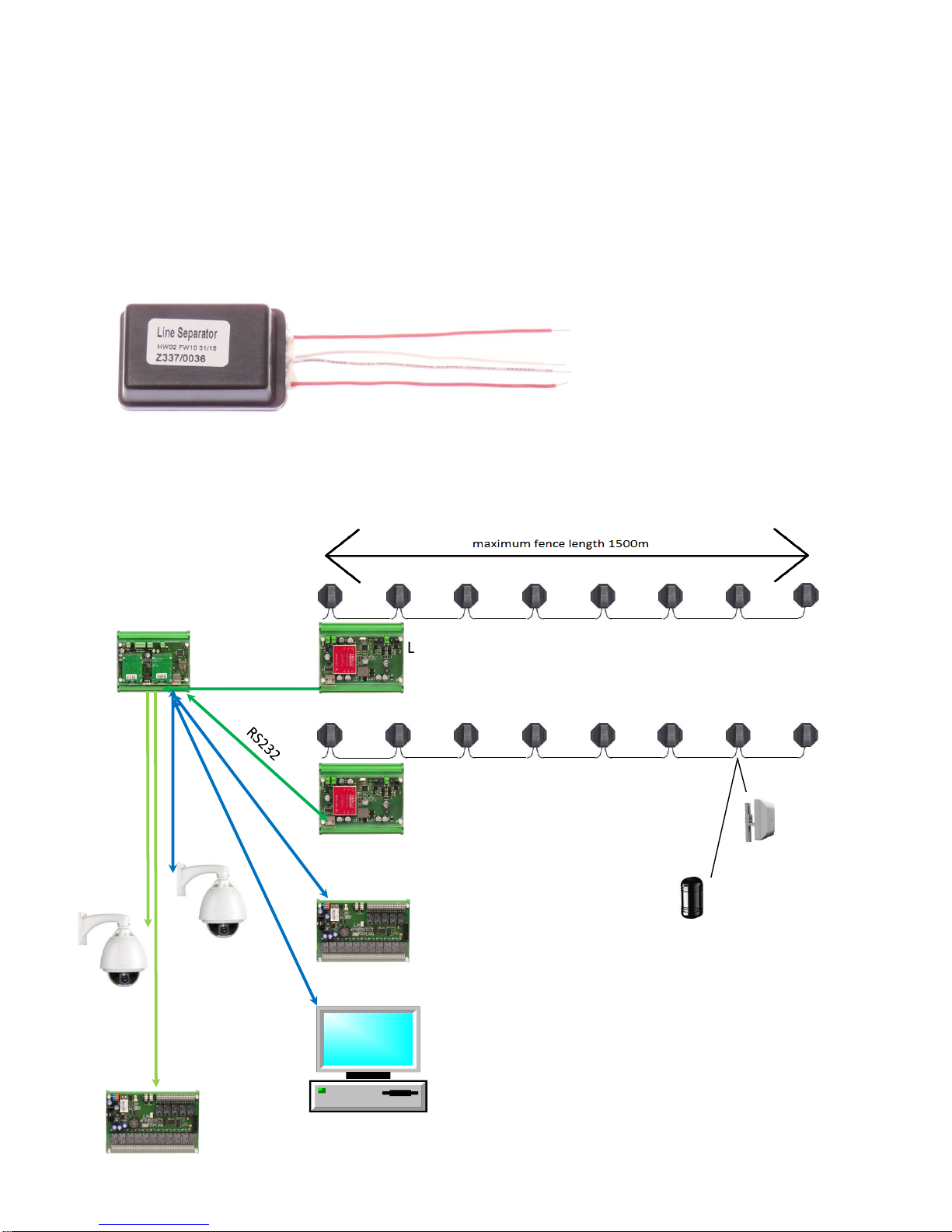
The line separator is placed in the same casing as the detector. Its purpose is to
separate/disconnect a part of the line that experiences a change in terms of electrical wiring
parameters such as short circuit, lead-in etc. The part is disconnected by insulators while the rest of
the line remains operational. This is why the insulator is equipped by two pairs of cable outlets.
These are both equal, no need to distinguish the inlet from the outlet. The line separators feature a
built-in overvoltage protection. That means that as long as there are separators fitted within a line, it
is fine to only provide enough overvoltage protection modules to satisfy the rule of 15 – 25 LPP
modules per line.
2.8. Block Diagram of the System
m
RS232
RS485
telemetry
TCP/IP
Rotary
analogue
camera
Visualization
SW
Rotary IP
camera
CUP+
TCP/IP
LSP+ Line Separator
LCP+
TCP/IP
LCP+
IOP+/LAN
DSP+
LSP+
LIP+
IOP+/RS485
Page 17

- 16 -
3. Technical Specification of PERIDECT+
3.1. CUP+ Control Unit PERIDECT+
Supply voltage: 9 – 16 VDC
Consumption: 160 mA
Operational temperature range: -40°C to +80°C
Inputs: 1x tamper contact
Outputs: 4x open collector type
Protection: IP20
Dimensions: 150 x 100 x 40 mm
3.2. LCP+ Line Controller PERIDECT+
Supply voltage: 9 – 16 VDC
Consumption: 60 mA (350 mA at full DSP+ capacity)
Default line voltage: 24V (36V when on or exceeding 1,5km of detection line)
Operational temperature range: -40°C to +85°C
Protection: IP20
Dimensions: 150 x 100 x 40 mm
3.3. LIP+ Line Input PERIDECT+
Power supply: powered by the line controller bus
Consumption: 2 mA max.
Operational temperature range: -40°C to +85°C
Inputs: 2x double-balanced (balancing resistors of 2 x 1k2 and 2 x 3k3)
Electronic elements protection: IP65
Dimensions: 50 x 30 x 20 mm (outer casing 110 x 110 x 40 mm)
3.4. DSP+ Detection Sensor PERIDECT+
Power supply: powered by the line controller bus
Consumption: 2 mA max.
Operational temperature range: -40°C to +85°C
Electronic elements protection: IP65
Dimensions: 50 x 30 x 20 mm (outer casing 110 x 110 x 40 mm)
3.5. LSP+ Line Separator PERIDECT+
Power supply: powered by the line controller bus
Consumption: typically 1 mA
Operational temperature range: -40°C to +85°C
Electronic elements protection: IP65
Dimensions: 50 x 30 x 20 mm (outer casing 110 x 110 x 40 mm)
Page 18

- 17 -
3.6. PERIDECT+ IOP+/LAN I/O Module
Supply voltage: 9 – 16 VDC
Consumption: 120 mA (620 mA at all relays switched on)
Operational temperature range: -25°C to +60°C
Protection: IP20
Dimensions: 190 x 130 x 50 mm
In case of connecting Expander module, it is necessary to connect it ONLY when the IOP
module is powered off.
3.7. PERIDECT+ IOP+/RS485 I/O RS485 Module
Supply voltage: 9 – 16 VDC
Consumption: 120 mA (620 mA at all relays switched on)
Operational temperature range: -25°C to +60°C
Protection: IP20
Dimensions: 190 x 130 x 50 mm
In case of connecting Expander module, it is necessary to connect it ONLY when the IOP
module is powered off.
3.8. PERIDECT+ IOP+/EXP I/O Expansion Module
Consumption: The consumption of IOP+/LAN or IOP+/RS485 is increased by 50 mA when the relays are off and by 500 mA when
all the relays are on
Operational temperature range: -25°C to +60°C
Protection: IP20
Dimensions: 140 x 130 x 50 mm
 Loading...