

Sievers TOC 800,TOC 810,TOC 820 Operation And Maintenance Manual

800 Series Total Organic Carbon Analyzer
Operation and Maintenance Manual
Minimum Firmware Version:
TOC Firmware Versions 3.52 (CAS) with or without
DataPro Autosampler Software, or
TOC Firmware Versions 3.62 (CAS) with
DataGuard and with or without DataPro Autosampler Software, or
TOC Firmware Versions 3.15 (CMS), or
TOC Firmware Versions 2.12 (CTB) Turbo, or
TOC Firmware Version 2.11 (CBI)
Instrument Business Group
6060 Spine Road
Boulder, CO 80301 USA
phone 800.255.6964 • 303.444.2009 • fax 303.444.9543 DLM 30007-08 Rev. A
www.IonicsInstruments.com Printed in USA 2004

Identification Records
Default Administrator Password: IIBG
Record the instrument’s serial number as it appears on the identification label located
on the left side panel of the instrument:
Instrument’s serial number
Record the date of receipt and installation of the instrument; this is the warranty start
date:
Date of receipt/installation of the instrument ______________
Ionics Instruments 2004 Page i DLM 30007-08 Rev. A

Revision History
New editions are complete revisions of the manual and incorporate all previous update pages and
write-in instructions. This manual will be revised as necessary. Revisions can be in the form of new
editions, update pages, or write-in instructions.
Revision A and B On-Line Software Versions 0.10 – 1.17......................................... July 1992
Revision C On-Line Software Version 2.0 and updates; Autosampler
Firmware Versions 20 – 30...................................................... July 1993
Revision D and E On-Line Software Version 2.0 and updates; Autosampler
Firmware Versions 20 – 30 ...........................................September 1994
Revision F Firmware Version 3.00 (AS or MS) and updates...........................May 1995
Revision G Firmware Version 3.06 (AS or MS) and updates; RAM Card
PC Software Version 3.08RC and updates; Autosampler
PC Software Version 3.07PC and updates.......................... August 1995
Revision H Appendices B and C updates...................................................... March 1996
Revision J Appendices B and C updates.................................................... January 1997
DLM 30007-01 Rev. A TUV rating; Firmware 3.13CAS, 3.12CMS, 2.0CTB,
3.11PRA .................................................................................. July 1998
DLM 30007-02 Rev. A Year 2000 Readiness................................................................ January 1999
DLM 30007-03 Rev. A New DI Loop Maintenance............................................................June 1999
DLM 30007-04 Rev. A Firm/Software Versions 3.20CAS, 2.11CTB and 3.20PRA .........April 2000
DLM 30007-05 Rev. A Firm/Software Versions 3.30CAS, 2.12CTB 2.11CBI ...............March 2001
DLM 30007-06 Rev. A Firm/Software Versions 3.50CAS, 3.60CAS.................................May 2003
DLM 30007-06 Rev. B Formatting Adjustments................................................................. July 2003
DLM 30007-07 Rev. A Firm/Software Version 3.51CAS ................................................... July 2003
DLM 30007-08 Rev. A Firm/Software Version 3.52CAS, 3.62CAS ............................October 2004
Ionics Instruments 2004 Page ii DLM 30007-08 Rev. A

Trademarks and Patents
Sievers is a registered trademark of Ionics Instrument Business Group; DataPro and DataGuard are
trademarks of Ionics Instrument Business Group.
Teflon
trademark of Norton Performance Plastics Corporation; Swagelok
Swagelok Company. Mininert
a registered trademark of Microsoft Corporation. Lotus 1-2-3
is a registered trademark of E.I. du Pont de Nemours and Company; Tygon is a registered
is a registered trademark of Valco Instruments Co. Inc. Windows is
is a registered trademark of the
is a registered trademark of IBM-Lotus
Corporation.
The analyzer described in this manual is covered by one or more patents issued to and owned or
pending by Ionics Instrument Business Group.
Confidentiality
The information contained in this manual may be confidential and proprietary and is the property of
Ionics Instrument Business Group. Information disclosed herein shall not be used to manufacture,
construct, or otherwise reproduce the goods disclosed herein. The information disclosed herein shall
not be disclosed to others or made public in any manner without the expressed written consent of the
Ionics Instrument Business Group.
Ionics Instruments 2004 Page iii DLM 30007-08 Rev. A

Standard Limited Warranty
Ionics Instrument Business Group warrants its products (Sievers™, Ionics™, and Leakwise™) for defects in materials and
workmanship. Ionics Instrument Business Group will, at its option, repair or replace instrument components that prove to be
defective with new or remanufactured components (i.e., equivalent to new). The warranty set forth is exclusive and no other
warranty, whether written or oral, is expressed or implied.
Warranty Term
The Ionics Instrument Business Group warranty term is thirteen (13) months ex-works, or twelve (12) months from
installation or start up by Ionics Instruments certified service personnel. In no event shall the standard limited warranty
coverage extend beyond thirteen (13) months from original shipment date.
Warranty Service
Warranty Service is provided to customers through telephone support (1-800-255-6964 or 1-888-245-2595), Monday Friday, from 8:00 a.m. to 5:00 p.m. (Mountain Time), excluding all company and legal holidays. Telephone support is
provided for troubleshooting and determination of parts to be shipped from Ionics Instrument Business Group to the customer
in order to return the product to operation. If telephone support is not effective, the product may be returned to Ionics
Instrument for repair or replacement. In some instances, suitable instruments may be available for short duration loan or
lease.
Ionics Instrument Business Group warrants that any labor services provided shall conform to the reasonable standards of
technical competency and performance effective at the time of delivery. All service interventions are to be reviewed and
authorized as correct and complete at the completion of the service by a customer representative, or designate. Ionics
Instrument Business Group warrants these services for 30 days after the authorization and will correct any qualifying
deficiency in labor provided that the labor service deficiency is exactly related to the originating event. No other remedy,
other than the provision of labor services, may be applicable.
Repair components (parts and materials), but not consumables, provided in the course of a repair, or purchased individually,
are warranted for 90 days ex-works for materials and workmanship. In no event will the incorporation of a warranted repair
component into an instrument extend the whole instrument’s warranty beyond its original term.
Consumables (e.g., dilution standards, verification solutions, reagents, and UV lamps, etc.) are warranted to the extent of
their stated shelf life, provided these items are maintained within the stated environmental limitations. Warranty claims for
consumables, reagents, and verification standards are limited to the replacement of the defective items, prorated from the
time of claim to the expiration of shelf life.
Shipping
A Repair Authorization Number (RA) must be obtained from the Technical Support Group before any product can be
returned to the factory. Ionics Instrument Business Group will pay freight charges, exclusive of any taxes and duties, for
replacement or repaired products shipped to the customer site. Customers shall pay freight charges, including all taxes and
duties, for all products returning to Ionics Instruments. Any product returned to the factory without an RA number will be
returned to the customer.
Limiting Conditions
The foregoing warranty shall not apply to defects resulting from improper or inadequate installation, maintenance,
adjustment, calibration, or operation by customer. Installation, maintenance, adjustment, calibration, or operation
must be performed in accordance with instructions stated in the Operation and Maintenance Manual. Usage of nonrecommended maintenance materials may void a warranty claim.
Limitation of Remedies and Liability
The remedies provided herein are the customer's sole and exclusive remedies. In no event shall Ionics Instrument Business
Group be liable for direct, indirect, special, incidental or consequential damages (including loss of profits) whether based on
contract, tort, or any other legal theory. The Operation and Maintenance Manual is believed to be accurate at the time of
publication and no responsibility is taken for any errors that may be present. In no event shall Ionics Instrument Business
Group be liable for incidental or consequential damages in connection with or arising from the use of the manual and its
accompanying related materials. Warranty is valid only for the original purchaser on the Ionics Instruments quote or invoice.
This Limited Warranty is not transferable from the original purchaser to any other party without the express written consent
from Ionics Instrument Business Group. Ionics Instrument Business Group specifically disclaims the implied warranties
of merchantability and fitness for a particular purpose.
Ionics Instruments 2004 Page iv DLM 30007-08 Rev. A
Declaration of Conformity
Ionics Instruments 2004 Page v DLM 30007-08 Rev. A

TABLE OF CONTENTS
IDENTIFICATION RECORDS.....................................................................................I
REVISION HISTORY .................................................................................................II
TRADEMARKS AND PATENTS ..............................................................................III
CONFIDENTIALITY..................................................................................................III
STANDARD LIMITED WARRANTY ........................................................................ IV
TABLE OF CONTENTS........................................................................................... VI
1 INTRODUCTION.............................................................................................. 1-1
Warnings – English ............................................................................................. 1-2
Warnings – Español ............................................................................................ 1-3
Warnings – Francais ........................................................................................... 1-4
Warnings – Deutsch............................................................................................ 1-5
Warnings – Italiano ............................................................................................. 1-6
Warnings – Dutch................................................................................................ 1-7
2 SYSTEM SPECIFICATIONS ........................................................................... 2-2
3 SYSTEM DESCRIPTION ................................................................................. 3-1
Sample Inlet Systems and Sample Pump ........................................................... 3-3
On-Line Sampling from Pressurized Source................................................................. 3-3
Grab Sampling .............................................................................................................. 3-3
Calibration Valve........................................................................................................... 3-4
Chemical Reagent Reservoirs............................................................................. 3-4
Chemical Reagent Syringe Pumps ..................................................................... 3-5
Stream Splitter .................................................................................................... 3-5
Oxidation Reactor ............................................................................................... 3-6
Sensors ....................................................................................................... 3-6
CO
2
DI Water Loop............................................................................................................... 3-7
Membrane Module ........................................................................................................ 3-7
Conductivity and Temperature Measurement Cell........................................................ 3-7
Microprocessor Controller and Electronics.......................................................... 3-8
On-board Data Storage....................................................................................... 3-8
Ionics Instruments 2004 Page vi DLM 30007-08 Rev. A

Data Outputs ....................................................................................................... 3-9
CO2 Sensor Measurement Cycle........................................................................ 3-9
Major Accessories and Configurations Available for the Analyzer .................... 3-10
IC Removal Module ....................................................................................................3-10
Autosampler................................................................................................................ 3-10
Multistream .................................................................................................................3-11
Turbo...........................................................................................................................3-12
Flow Switch and Binary Input Module......................................................................... 3-12
Ozone Destruct Kit...................................................................................................... 3-12
Environmental Enclosure............................................................................................ 3-12
Front Panel Displays and Controls.................................................................... 3-13
4 INSTALLATION............................................................................................... 4-1
Unpacking and Inspecting ................................................................................... 4-1
Collecting Additional Equipment.......................................................................... 4-2
Site Selection/Location........................................................................................ 4-3
Power Requirements........................................................................................... 4-3
Environmental Consideration .............................................................................. 4-3
Installing Sample Port ......................................................................................... 4-3
Plumbing....................................................................................................................... 4-4
Installing On-Line Sample Inlet System – ............................................................................................. 4-4
Installing Grab Sample Inlet System –................................................................................................... 4-5
Electrical.............................................................................................................. 4-8
Installing the Recorder, Alarm, and Printer Cables - Wiring .........................................4-8
Recorder and Alarm Outputs ........................................................................................ 4-9
Printer Cable ............................................................................................................... 4-11
Installing Reagent Cartridges ............................................................................ 4-11
Selecting the Sample Mode .............................................................................. 4-14
Entering the Date and Time .............................................................................. 4-17
Enter the Installation Dates for Reagents.......................................................... 4-17
Oxidizer Reagent ........................................................................................................ 4-18
Acid Reagent ..............................................................................................................4-20
Selecting Oxidizer and Acid Flow Rates............................................................ 4-21
Preset Flow Rates....................................................................................................... 4-24
Manual/Grab Flow Rates ............................................................................................ 4-26
Setting Up a Password...................................................................................... 4-29
Entering Printer Setup....................................................................................... 4-30
Print Interval................................................................................................................4-32
Print Constants.................................................................................................. 4-33
Reagent Flush................................................................................................... 4-33
5 ANALOG AND DIGITAL OUTPUTS................................................................ 5-1
Baud Rate ........................................................................................................... 5-1
RS-232 Data Out................................................................................................. 5-2
Serial Commands .........................................................................................................5-5
Alarms................................................................................................................. 5-7
Analog Outputs ................................................................................................... 5-9
Ionics Instruments 2004 Page vii DLM 30007-08 Rev. A

Display .............................................................................................................. 5-11
Warning 42........................................................................................................ 5-12
6 OPERATION AND DISPLAY MENUS............................................................. 6-1
Menu Map ........................................................................................................... 6-2
Main Menu .......................................................................................................... 6-3
Power-Up and Initialization (On-Line Sampling).................................................. 6-3
Measurement Display.......................................................................................... 6-5
RunTime Menu.................................................................................................... 6-6
History...........................................................................................................................6-7
Errors ............................................................................................................................6-9
Stop TOC .................................................................................................................... 6-10
Viewing Consumables Status............................................................................ 6-10
UV Lamp Status.......................................................................................................... 6-11
Reagent Status ........................................................................................................... 6-12
Fatal Error Display ............................................................................................ 6-14
Turning Off Power to the Analyzer .................................................................... 6-14
Grab Sample Measurements ............................................................................ 6-15
Setting the Sample Mode to Grab Sampling............................................................... 6-16
Changing from On-line to Grab Sampling................................................................... 6-17
Setting Up the Grab Sample Mode ............................................................................. 6-17
Running Grab Samples............................................................................................... 6-22
Changing to or Returning to On-line Measurements ..................................................6-24
Changing the Password .................................................................................... 6-26
Disabling Password Protection.......................................................................... 6-29
Service Menu .................................................................................................... 6-29
7 DATAGUARD OPERATION............................................................................ 7-1
Menu Map ........................................................................................................... 7-2
Main Menu .......................................................................................................... 7-3
RunTime Menu.................................................................................................... 7-3
Stop TOC Option ..........................................................................................................7-4
Setup................................................................................................................... 7-5
Admin.................................................................................................................. 7-6
Password ...................................................................................................................... 7-6
Entering a Password –............................................................................................................................ 7-8
Setting a Password – .............................................................................................................................. 7-9
Disabling a Password – ........................................................................................................................ 7-11
Login Timeout ............................................................................................................. 7-11
Audit Trail .......................................................................................................... 7-12
View Audit Trail ........................................................................................................... 7-14
Print Audit Trail ...........................................................................................................7-14
Export Audit Trail ........................................................................................................7-15
Reset Audit Trail .........................................................................................................7-16
Logging Out....................................................................................................... 7-17
8 MAINTENANCE............................................................................................... 8-1
Ionics Instruments 2004 Page viii DLM 30007-08 Rev. A

Replacing the In-line Filter................................................................................... 8-2
Replacing the Reagents ...................................................................................... 8-4
Replacing the UV Lamp ...................................................................................... 8-8
Replacing the Pump Tubing .............................................................................. 8-12
Entering the Installation Dates for Reagents, UV Lamp, and Pump Tubing ...... 8-15
Oxidizer Reagent ........................................................................................................ 8-16
Acid Reagent ..............................................................................................................8-18
Lamp........................................................................................................................... 8-19
Pump Tubing............................................................................................................... 8-20
Checking and Refilling the DI Water Reservoir ................................................. 8-22
Cleaning the Analyzer ....................................................................................... 8-23
9 CALIBRATION ................................................................................................ 9-1
Supplies for TC and IC Standards....................................................................... 9-2
TC Zero Offset .................................................................................................... 9-3
TC Calibration Constant ...................................................................................... 9-8
IC Calibration Constant ..................................................................................... 9-15
TC and IC Calibration Verification ..................................................................... 9-19
10 TROUBLESHOOTING................................................................................ 10-1
Checking the Error Stack .................................................................................. 10-1
Corrective Actions ............................................................................................. 10-4
Printing the Error Stack ..................................................................................... 10-9
No Power to the Analyzer.................................................................................. 10-2
No Flow Through the Analyzer.......................................................................... 10-3
On-line Sampling ........................................................................................................10-4
Grab Sampling ............................................................................................................ 10-4
pH Of Sample Stream Is Too High.................................................................... 10-5
Measure the pH (non-deionized water only) ............................................................... 10-5
Oxidizer Flow Rate Too High ............................................................................ 10-6
Oxidizer Flow Rate Too Low ............................................................................. 10-6
DI Reservoir Too Low........................................................................................ 10-7
Gas Bubbles in Reagent Lines or Syringes....................................................... 10-7
Negative or Zero TOC Measurements .............................................................. 10-8
Diagnostic Testing........................................................................................... 10-11
Syringe Pump.................................................................................................. 10-12
Returning the Analyzer to Ionics Instruments.................................................. 10-12
Preparing the Analyzer for Return Shipment ............................................................ 10-13
Repackaging the Analyzer for Shipment................................................................... 10-16
11 RAM CARDS, CARD READER, AND RAMREADER SOFTWARE.......... 11-2
Installing the Card Reader Hardware ................................................................ 11-2
Installing RAMReader Software ........................................................................ 11-2
Removing the RAM Card .................................................................................. 11-2
Placing the RAM Card in the Card Reader Device............................................ 11-3
Installing the RAM Card in the Analyzer............................................................ 11-4
Ionics Instruments 2004 Page ix DLM 30007-08 Rev. A

RAM Card Battery Maintenance........................................................................ 11-5
APPENDIX A – 810/810AS ANALYZER OPERATING FREQUENCY .................A-1
Selecting the Operating Frequency..................................................................... A-1
Calibration ........................................................................................................... A-2
APPENDIX B – 820/820AS ANALYZER OPERATING FREQUENCY .................B-1
Checking the Operating Frequency..................................................................... B-1
CE Mark Compliance .......................................................................................... B-2
Printer Cable ....................................................................................................... B-2
APPENDIX C - TURBO TOC ANALYZERS ..........................................................C-1
Introduction .........................................................................................................C-1
Setting Turbo Sampling Model ............................................................................C-2
Setting Reagent Flow Rates................................................................................C-3
Setting Alarms.....................................................................................................C-5
Calibration in Turbo Sampling Mode ...................................................................C-5
Turbo Mode TC Zero Offset......................................................................................... C-6
Turbo Mode TC Channel Calibration ........................................................................... C-7
Turbo Mode IC Channel Calibration ............................................................................ C-8
Alarm Settings.....................................................................................................C-9
Accuracy Specifications ......................................................................................C-9
APPENDIX D – BINARY INPUT MODULE – FLOW SWITCH..............................D-1
Mechanical Installation ........................................................................................ D-2
Firmware Installation ...........................................................................................D-4
Replacing the EEPROM Chip (IC chip) ....................................................................... D-4
Replacing the IC Chip from an Zero Insertion Force-type Socket –..................................................... D-4
Replacing the IC Chip from a Low Profile-type Socket – .................................................................... D-6
Software Configuration........................................................................................D-8
APPENDIX E – CALIBRATION STANDARD PREPARATION............................. E-1
Preparing the TC Calibration Standard ...............................................................E-1
Part 1 – Measure TC of Water Used for Preparing Standards .....................................E-1
Part 2 – Prepare a Stock TC Standard .........................................................................E-4
Part 3 – Prepare a Dilute TC Standard ........................................................................E-5
Preparation of the IC Calibration Standard.......................................................... E-5
Part 1 – Prepare a Stock IC Standard: .........................................................................E-5
Part 2 – Prepare a Dilute IC Standard: ........................................................................E-7
APPENDIX F – CONSUMABLES AND ACCESSORIES ...................................... F-1
Ionics Instruments 2004 Page x DLM 30007-08 Rev. A

TABLES
Table 1. Analog Outputs on Terminal Strip ...........................................4-10
Table 2. Recommended Reagent Flow Rates........................................4-23
Table 3. Preset Acid and Oxidizer Flow Rates ......................................4-24
Table 4. RS-232 Data Output Format ........................................................5-3
Table 5. Operating Messages....................................................................6-6
Table 6. User IDs.........................................................................................7-7
Table 7. RS-232 Audit Trail Output Format............................................7-16
Table 8. Replacement/Maintenance Schedule.........................................8-1
Table 9. Available RAM Cards and Storage Capacity.............................8-2
Table 10. Warnings and Error Messages ...............................................10-3
Ionics Instruments 2004 Page xi DLM 30007-08 Rev. A

1 INTRODUCTION
The Sievers 800 Series Total Organic Carbon (TOC) Analyzer from Ionics
Instruments (U.S. Patent No. 5,132,094) is a high-sensitivity analyzer used to
measure the concentration of total organic carbon (TOC), total inorganic carbon
(TIC), and total carbon (TC = TOC+ TIC) in all water samples. The 800
designation is for 120V systems, 810 is for 100 V systems and 820 designation
is for 230V systems (generically referred to as a Sievers 800 TOC Analyzer).
The analyzer is based on the oxidation of organic compounds to form carbon
dioxide using UV radiation and a chemical oxidizing agent (ammonium
persulfate). Carbon dioxide is measured using a sensitive and selective
membrane-based conductometric detection technique as described by Carlson
(R. M. Carlson, "Method and Apparatus for the Determination of Volatile
Electrolytes", U.S. Patent No. 4,209,299, licensed by Ionics Instruments) For
each TOC measurement, the concentration of inorganic carbon species (CO
HCO
-
, and CO
3
2
-
) is determined and, after oxidation of the organic compounds,
3
,
2
the total carbon content of the sample is measured. The concentration of the
organic compounds is then calculated from the difference between total carbon
and total inorganic carbon concentrations
(TOC=TC–TIC).
The analyzer can be used to monitor water samples ranging from high-purity
water containing < 0.5 parts per billion carbon to water samples containing up to
50 parts per million TOC. The analyzer is easy to operate, with extremely low
maintenance, and no special training or chemical knowledge required for
preparing reagents. The analyzer is calibrated at the factory, with the calibration
stable for approximately one year. Recalibration and validation can be easily
performed at the user’s site.
NOTE
Throughout this manual, the term Sievers 800 TOC Analyzer refers to all models
(800/810/820) of the analyzer.
Ionics Instruments 2004 Page 1-1 DLM 30007-08 Rev. A

Warnings – English
Any operation requiring access to the inside of the equipment could result in
injury. To avoid potentially dangerous shock, disconnect from power supply
before opening the equipment.
For continued protection against fire hazard, replace fuse with same type and
rating.
WARNING
WARNING
WARNING
This symbol, on the instrument indicates that the user should refer to the
manual for operating instructions.
WARNING
This is a Safety Class I product. It must be wired to a mains supply with a
protective earthing ground incorporated into the power cord. Any interruption of
the protective conductor, inside or outside the equipment, is likely to make the
instrument dangerous. Intentional interruption is prohibited.
WARNING
If this instrument is used in a manner not specified by Ionics Instruments Business
Group USA, the protection provided by the instrument may be impaired.
WARNING
Disposal of RAM card Lithium batteries must follow local environmental
regulations.
Ionics Instruments 2004 Page 1-2 DLM 30007-08 Rev. A
Warnings – Español
Cualquier operación que requiera acceso al interior del equipo, puede causar una
lesión. Para evitar peligros potenciales, desconectarlo de la alimentación a red
antes de abrir el equipo.
Para protección contínua contra el peligro de fuego, sustituir el fusible por uno del
mismo tipo y características.
ATENCION
ATENCION
ATENCION
Este símbolo, en el instrumento indica que el usuario debería referirse al manual
para instrucciones de funcionamiento.
ATENCION
Esto es un producto con clase I de seguridad. Debe conectarse a una red que
disponga de tierra protectora en el cable de red. Cualquier interrupción del
conductor protector, dentro o fuera del equipo, puede ser peligroso. Se prohibe la
interrupción intencionada.
ATENCION
Si este instrumento se usa de una forma no especificada por Ionics Instruments
Business Group, USA, puede desactivarse la protección suministrada por el
instrumento.
ATENCION
Las pilas de litio de la RAM card deshechadas deben seguir las regulaciones
medioambientales locales.
Ionics Instruments 2004 Page 1-3 DLM 30007-08 Rev. A
Warnings – Francais
Chaque opération à l’intérieur de l’appareil, peut causer du préjudice. Afin
d’éviter un shock qui pourrait être dangereux, disconnectez l’appareil du réseau
avant de l’ouvrir.
Afin de protéger l’appareil continuellement contre l’incendie, échangez le fusible
par un fusible du même type et valeur.
ATTENTION
ATTENTION
ATTENTION
Le symbol, indique que l’utilisateur doit consulter le manuel d’instructions.
ATTENTION
Ceci est un produit de Classe de sécurité I. L’instrument doit être branché sur
l’alimentation secteur par un fil de secteur prévu d’une prise de masse. Chaque
interruption du conducteur protégeant, à l’intérieur ou á l’extérieur de l’appareil
peut rendre l’instrument dangereux. Interruption intentionnelle est interdite.
ATTENTION
Si l’instrument n’est pas utilisé suivant les instructions de Ionics Instruments
Business Group, USA, les dispositions de sécurité de l’appareil ne sont plus
valables.
ATTENTION
Les batteries RAM card Lithium doivent être déposés suivant les régulations
d’environnement locales.
Ionics Instruments 2004 Page 1-4 DLM 30007-08 Rev. A
Warnings – Deutsch
Vor dem Öffnen des Gerätes Netzstecker ziehen!
Für kontinuierlichen Schutz gegen Brandgefahr dürfen bei Sicherungswechsel nur
Sicherungen der gleichen Stärke verwendet werden!
Dieses Symbol auf dem Gerät weist darauf hin, dass der Anwender zuerst das
entsprechende Kapitel in der Bedienungsanleitung lesen sollte.
WARNHINWEIS
WARNHINWEIS
WARNHINWEIS
WARNHINWEIS
Dies ist ein Gerät der Sicherheitsklasse I und darf nur mit einem Netzkabel mit
Schutzleiter betrieben werden. Jede Unterbrechung des Schutzleiters auβerhalb
oder innerhalb des Gerätes kann das Gerät elektrisch gefährlich machen.
Absichtliches Unterbrechen des Schutzleiters ist ausdrücklich verboten.
WARNHINWEIS
Wenn das Gerät nicht wie durch die Firma Ionics Instruments Business Group,
USA, vorgeschrieben und im Handbuch beschrieben betrieben wird, können die im
Gerät eingebauten Schutzvorrichtungen beeinträchtigt werden.
WARNHINWEIS
Die Entsorgung der Lithium-Batterie in der RAM-Karte darf nur nach den
geltenden Umweltschutzregeln erfolgen.
Ionics Instruments 2004 Page 1-5 DLM 30007-08 Rev. A
Warnings – Italiano
Qualsiasi intervento debba essere effettuato sullo strumento può essere
potenzialmente pericoloso a causa della corrente elettrica. Il cavo di alimentazione
deve essere staccato dallo strumento prima della sua apertura.
Per la protezione da rischi da incendio in seguito a corto circuito, sostituire I
fusibili di protezione con quelli dello stesso tipo e caratteristiche.
ATTENZIONE
ATTENZIONE
ATTENZIONE
Il simbolo, sullo strumento avverte l’utilizzatore di consultare il Manuale di
Istruzioni alla sezione specifica.
ATTENZIONE
Questo strumento è conforme alle specifiche per I prodotti in Classe I - Il cavo di
alimentazione dalla rete deve essere munito di “terra”. Qualsiasi interruzione del
cavo di terra all’interno ed all’esterno dello strumento potrebbe risultare
pericolòsa. Sono proibite interruzioni intenzionali.
ATTENZIONE
Se questo strumento viene utilizzato in maniera non conforme alle specifiche di
Ionics Instruments Business Group USA, le protezioni di cui esso è dotato
potrebbero essere alterate.
ATTENZION
Le batterie al Litio sulla RAM card, quando sono esaurite, devono essere gettate
secondo le regolamentazioni vigenti localmente.
Ionics Instruments 2004 Page 1-6 DLM 30007-08 Rev. A
Warnings – Dutch
Iedere handeling binnenin het toestel kan beschadiging veroorzaken. Om iedere
mogelijk gevaarlijke shock te vermijden moet de aansluiting met het net verbroken
worden, vóór het openen van het toestel.
Voor een continue bescherming tegen brandgevaar, vervang de zekering door een
zekering van hetzelfde type en waarde.
OPGELET
OPGELET
OPGELET
Het symbool, geeft aan dat de gebruiker de instructies in de handleiding moet
raadplegen.
OPGELET
Dit is een produkt van veiligheidsklasse I. Het toestel moet aangesloten worden op
het net via een geaard netsnoer. Bij onderbreking van de beschermende geleider,
aan de binnenzijde of aan de buitenzijde van het toestel, kan gebruik het toestel
gevaarlijk maken. Opzettelijke onderbreking is verboden.
OPGELET
Indien het toestel niet gebruikt wordt volgens de richtlijnen van Ionics Instruments
Business Group, USA gelden de veiligheidsvoorzieningen niet meer.
OPGELET
RAM kaart Lithium batterijen dienen volgens de lokale afvalwetgeving verwijderd
te worden.
Ionics Instruments 2004 Page 1-7 DLM 30007-08 Rev. A
WARNING
For on-line applications, an in-line particle filter must be installed on the sample
inlet line to prevent damage to the instrument. If the water sample to be monitored
contains high levels of suspended solids, then the in-line filter must be replaced on
a regular basis.
WARNING
Do not run the instrument with the sample inlet line capped off as this can result in
false TOC readings and possible damage to the instrument.
WARNING
Hazardous chemical reagents (ammonium persulfate and phosphoric acid) are used
in the instrument. The waste stream from the instrument is acidic and must be
disposed of properly. Consult your state and local regulations.
WARNING
Do not adjust the pressure regulator on the sample inlet system. The pressure is
preset to 5 psi. Changing the inlet pressure can damage the analyzer and void the
warranty. Do not let the inlet pressure exceed 5 psi.
WARNING
Always stop TOC measurements before turning off or unplugging the instrument.
Turning off the instrument while it is writing to the RAM card may damage the
card.
WARNING
Make sure the DI Reservoir is full, particularly when running samples with high
TOC or high salt concentrations. Always “clean-up” the instrument by running
low TOC DI water after running high TOC or salt samples.
WARNING
This is a Class A product. In a domestic environment, this product may cause
electromagnetic interference in which case the user may be required to take
adequate measures to correct the interference.
Ionics Instruments 2004 Page 1-8 DLM 30007-08 Rev. A
WARNING
For performance within specifications on ozonated water systems, an Ozone
Destruct Kit must be purchased from Ionics Instruments and installed according to
instructions.
WARNING
The UV lamp contains mercury and may be considered hazardous material in your
local area. Dispose of the UV lamp in accordance with Federal, state, or local
government regulations.
WARNING
Installation of the UV lamp requires access to the inside of the instrument. To
avoid potentially dangerous shock, disconnect the power cord before opening the
instrument's top panel.
WARNING
Should the UV lamp become broken or damaged it should be handled in
accordance with your organization’s toxic waste handling procedure and disposed
of in accordance with Federal, state, or local government regulations.
Ionics Instruments 2004 Page 1-9 DLM 30007-08 Rev. A

Ionics Instruments 2004 Page 1-1 DLM 30007-08 Rev. A

2 SYSTEM SPECIFICATIONS
Detection limit..........................................0.05 ppb TOC
On-Line TOC Precision ...........................± 3% of Total Carbon value
On-Line TOC Accuracy ...........................± 3% of TC value (TC > 100 ppb)
Interferences ...........................................Insensitive to halogenated
hydrocarbon interference
Linear range ............................................0.05 – 50,000 ppb TOC
Analysis Time .........................................6 minutes
Sample Temperature...............................1 to 100°C
Ambient Temperature..............................10 to 40°C
Sample Pressure.....................................Up to 100 psi
Sample Flow Rate…………………………30 to 220 mL/min
Internal Sample Flow Rate ......................0.35mL/minute
Maximum Relative Humidity....................80% at 31°C; 50% at 40°C
Maximum Altitude ....................................up to 3,048m
Calibration Stability..................................Typically stable for 12 months
Chemical Reagents .................................Prepackaged, 3-month supply
Outputs ....................................................0–10 V and 4–20 mA, RS-232,
parallel printer port, alarms
Power requirements
Model 800 120 V, 150 watts, 60 Hz
Model 810 100 V, 150 watts, 50/60 Hz
Model 820 230 V(±10%), 150 watts, 50/60
Hz
Ionics Instruments 2004 Page 2-2 DLM 30007-08 Rev. A

Installation/Overvoltage Category ...........II
Pollution Degree......................................II
Display.....................................................Back-lit, 3 significant digits
Size .........................................................57 cm x 37 cm x 15 cm
Weight .....................................................13.6 kg
Ionics Instruments 2004 Page 2-2 DLM 30007-08 Rev. A

3 SYSTEM DESCRIPTION
The Sievers 800 TOC Analyzer consists of nine major components:
• Sample inlet system and sample pump
• Chemical reagent reservoirs
• Chemical reagent syringe pumps
• Stream splitter
• Oxidation reactor
• CO
sensors consisting of:
2
Deionized water loop
Membrane module
Conductivity and temperature-measurement cell
• Microprocessor controller and electronics
• On-board data storage
• Data outputs
Figure 3-1 shows a generalized schematic of the analyzer.
Ionics Instruments 2004 Page 3-1 DLM 30007-08 Rev. A
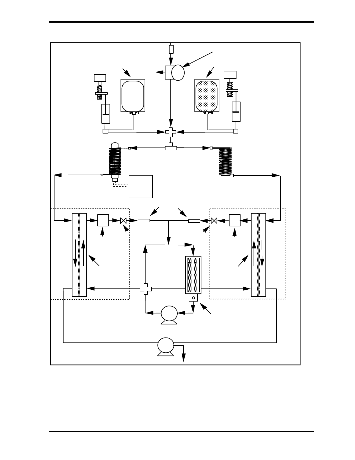
A
A
IN-LINE
CID
RESERVOIR
SAMPLE
INLET
WASTE
FILTER
PRESSURE
REGULATOR
PEROXYDISULFATE
RESERVOIR
CID
SYRINGE
PUMP
TOTAL CARBON
CO SENSOR
2
TEMPERATURE,
CONDUCTIVITY
SENSOR
MEMBRANE
MODULE
OXIDATION
REACTOR
LAMP
POWER
SUPPLY
SOLENOID
VALVE
RESTRICTORS
DEIONIZED
WATER
LOOP
SOLENOID
VALVE
PEROXYDISULFATE
DELAY
COIL
TOTAL INORGANIC
CARBON CO SENSOR
TEMPERATURE,
CONDUCTIVITY
SENSOR
MEMBRANE
MODULE
SYRINGE
PUMP
2
DI WATER
PUMP
WASTE
FILL PORT
FIGURE 3-1: Analyzer Schematic
A brief description of the major components of the analyzer follows.
Ionics Instruments 2004 Page 3-2 DLM 30007-08 Rev. A

Sample Inlet Systems and Sample Pump
On-Line Sampling from Pressurized Source
Water from a high-pressure line (> 5 psig) is introduced into the analyzer using
a sample inlet system. The system consists of:
• two lengths of 1/4" OD PFA tubing
• a 60-µm stainless steel in-line filter
• an in-line pressure regulator
• a sample interface box that includes:
• a pressure gauge
• back-pressure orifice
• a sample inlet line to the analyzer
• a sample outlet.
The temperature of the water to the inlet system can range from 1-100° C.
The flow rate of water through the inlet system can range from 30-220
mL/minute. The in-line pressure regulator reduces the pressure of the water
to 3-7 psig (5 psig at 25 °C). Water is drawn into the analyzer by a sample
pump at a flow rate of approximately 0.35 mL/min. A pressure > 5 psig will be
indicated by the gauge for water samples at temperatures < 25 °C (lower
pressure for water > 25 °C). The inlet system can also be used for water
samples at pressures below 5 psig as long as the flow through the inlet system
is at least 30 mL/min. For most applications, the waste stream from the
analyzer is mixed with the effluent from the sample inlet system and
discharged to a drain.
Grab Sampling
The analyzer can also be used to sample directly from a sample bottle or other
non-pressurized container for the analysis of grab samples, standards, and
other off-line operations. The samples should be filtered (60 µm or finer) to
prevent clogging of the analyzer by particles in the sample. The inlet line from
the sample inlet system is a 1/16" OD Teflon
tubing and the sample pump
Ionics Instruments 2004 Page 3-3 DLM 30007-08 Rev. A
draws the sample into the analyzer at a flow rate of about 0.35 mL/min. The
waste is removed through a second 1/16" OD Teflon tube to a waste
container. The 1/16" OD Teflon tubes are found in the accessories kit.
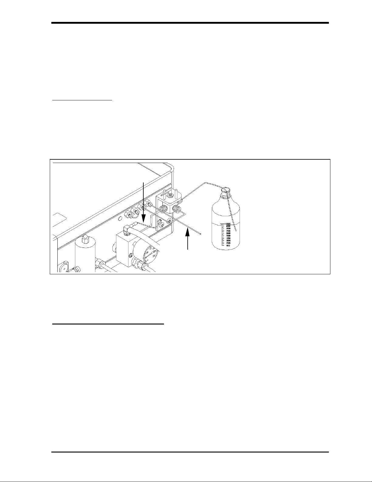
Calibration Valve
The analyzer can also be equipped with a two-position switching valve.
Installed at the inlet to the analyzer, this valve allows switching between online and container sampling without removing any tubing. The valve does not
contaminate the sample, even for low-level TOC measurements.
Remove on-line waste line
To waste bottle
Figure 3-2: View of Calibration Valve
Chemical Reagent Reservoirs
Two chemical reagents are used in the analyzer: 6M phosphoric acid (H
and 15% ammonium persulfate ((NH
4)2S2O8
). A supply of these reagents for
3PO4
)
approximately three months of continuous operation is stored in sealed
containers in the analyzer. The reagents are prepared using low-TOC,
deionized water under controlled conditions. The reagents are then packaged
to eliminate possible contamination of the sample by organic compounds.
When exhausted, the reagent supplies are simply replaced.
Ionics Instruments 2004 Page 3-4 DLM 30007-08 Rev. A

The oxidizing reagent – ammonium persulfate – is inherently unstable, slowly
decomposing to form sulfate ion and oxygen. The reagent is stored in a microporous Teflon bag container to permit the oxygen to diffuse from solution. The
decomposition of the persulfate limits the useful lifetime of this reagent to three
months, regardless of the volume of reagent consumed by operating the
analyzer. Although the volume for the phosphoric acid reagent is sufficient for
three months under typical operating conditions, the shelf life is one year.
The analyzer’s firmware keeps track of the volume of both reagents consumed
and the age of the persulfate solution. Warning messages indicate when new
reservoirs must be installed.
Chemical Reagent Syringe Pumps
The reagents are added to the sample stream using microprocessor-controlled
syringe pumps. The capacity of each syringe is 0.5 mL.
Typically, phosphoric acid is added at a flow rate of 0.2 – 1.5 µL/minute,
dependent upon initial sample pH and TOC concentration, to reduce the pH of
the sample stream to pH <2.
For water samples containing up to 5ppm TOC, 0.75µL/min is a suitable flow
rate for persulfate oxidizer. For samples containing higher levels of TOC (up
to 50 ppm), the oxidizer flow rate may be increased to 4.5 µL/min. or higher.
Stream Splitter
After the addition of the chemical reagents, the sample stream is split into two
equal flows. One stream passes through a delay coil and into a CO
sensor,
2
which measures the concentration of total inorganic carbon (TIC), or simply
“IC”. The other stream passes through the oxidation reactor that
photochemically oxidizes organic compounds to form CO
, and into a CO2
2
sensor that measures the concentration of total carbon (TC). As total carbon is
the sum of organic and inorganic carbon, the concentration of total organic
carbon is computed as the difference between the total and inorganic carbon
(TOC = TC–TIC).
Ionics Instruments 2004 Page 3-5 DLM 30007-08 Rev. A

Oxidation Reactor
The analyzer oxidizes organic compounds to CO
using the chemical oxidizing
2
agent ammonium persulfate, and UV radiation. The oxidation reactor is a
spiral quartz tube wrapped around an UV lamp. The lamp emits light at 184
and 254 nanometers, resulting in the formation of powerful chemical oxidizing
agents from the photolysis of water and persulfate:
H
O + hn (184 nm) OH. + H. (1)
2
-
2
O
S
+ hn (254 nm) 2 SO
2
8
.-
(2)
4
SO
.-
+ H
4
O HSO
2
-
+ OH. (3)
4
Hydroxyl radical (OH.) will completely oxidize organic compounds to form
carbon dioxide:
Organic Compounds + OH. CO
+ H2O (4)
2
When low levels of organic compounds (< 1 ppm) are present in the sample,
complete oxidation can usually be achieved by hydroxyl radicals produced
from the photolysis of water, without the addition of persulfate.
The lifetime of the UV lamp is approximately 6 months of operation and a
warning message will indicate when it is time to replace the lamp.
Sensors
CO
2
Two membrane-based conductometric CO
in the analyzer. One DI water source serves both sensors and each CO
sensors, a TC and an IC, are used
2
2
sensor consists of a membrane module, and a conductivity and temperature
measurement cell. The IC sensor measures the concentration of CO
in the
2
sample (without oxidation). The TC sensor measures the combined
concentration of CO
initially in the sample and CO2 produced by the oxidation
2
of organic compounds.
Ionics Instruments 2004 Page 3-6 DLM 30007-08 Rev. A
 Loading...