

OPERATING
MANUAL
Operating Manual
Handset Wireless
Mode D’emploi
Combiné sans fi l
Bedienungsanleitung
Drahtloses Handgerät
Bedieningsaanwijzing
Draadloos handapparaat
Manual De Instrucciones
Auricular Inalámbrico
Руководство По Зксплуатации
Беспроводное Дистанционное Управление
Kullanım Kılavuzu
Kablosuz Kulaklık
Εγχειρίδιο Οδηγιών
Ασύρματη Χειροσυσκευή
English
Français
Deutsch
Nederlands
Español
Pycckий
Türkçe
Ελληνικά
Manual De Funcionamento
Aparelho Sem Fios
OM-NET3C-0411(0)-SIESTA
Part No.: R08019036598
Portugues


ARCWA OUTLOOK
i
Battery
1) Type: AAA.R03
2) Quantity: 2 pieces
Disposal Requirements
The batteries supplied with the controller are marked with this symbol.
This means that the batteries shall not be mixed with unsorted household waste.
If a chemical symbol is printed beneath the symbol, this chemical symbol means that
the battery contains a heavy metal above a certain concentration.
Possible chemical symbols are:
n Pb: lead (>0,004%)
Waste batteries must be treated at a specialized treatment facility for re-use. By ensuring correct
disposal, you will help to prevent potential negative consequences for the environment and human
health. Please contact your local authority for more information.
»Í»ËÀÚ
ГК!!!2
¥ЙЖГТАМН½ЙУНОЕГ
®НГЖГВ»СГЪЙНРЙ¿Й½
¨»¼»Н»ЛАГЕЙНЙЛЦА½РЙ¿ЪН½ЕЙЗКЖАЕНКЙМН»½ЕГЕЙИНЛЙЖЖАЛ»И»ИАМАИ¿»ИИЦД
МГЗ½ЙЖ
¸НЙЙВИ»Т»АНТНЙ¼»Н»ЛАГИАЖЧВЪОНГЖГВГЛЙ½»НЧ½ЗАМНАМИАМЙЛНГЛЙ½»ИИЦЗГ
¼ЦНЙ½ЦЗГЙНРЙ¿»ЗГ
МЖГИГБАМГЗ½ЙЖ»И»ИАМАИ ВИ»ЕРГЗГТАМЕЙ¾ЙШЖАЗАИН»ЙИ ЙВИ»Т»АНТНЙ½
¼»Н»ЛААМЙ¿АЛБ»НМЪНЪБАЖЦАЗАН»ЖЖЦ½ЦУАЙКЛА¿АЖАИИЙДЕЙИСАИНЛ»СГГ
МНЛАТ»ЩФГАМЪРГЗГТАМЕГАВИ»ЕГ
n0B̽ÃÈÀÑ
®НГЖГВГЛОАЗЦА¼»Н»ЛАГ¿ЙЖБИЦКАЛАЛ»¼»НЦ½»НЧМЪИ»МКАСГ»ЖЧИЙЗКАЛАЛ»¼»НЦ½»ЩФАЗ
КЛА¿КЛГЪНГГ¿ЖЪГР КЙ½НЙЛИЙ¾ЙГМКЙЖЧВЙ½»ИГЪ©¼АМКАТГ½КЛ»½ГЖЧИОЩ ОНГЖГВ»СГЩЦ
КЙЗЙБАНАКЛА¿ЙН½Л»НГНЧКЙНАИСГ»ЖЧИЦАИА¾»НГ½ИЦАКЙМЖА¿МН½ГЪ¿ЖЪЙЕЛОБ»ЩФАДМЛА¿Ц
ГВ¿ЙЛЙ½ЧЪЖЩ¿АДЖЪКЙЖОТАИГЪ¿ЙКЙЖИГНАЖЧИЙДГИПЙЛЗ»СГГКЙБ»ЖОДМН»Й¼Л»НГНАМЧ½
ЗАМНИЦАЙЛ¾»ИЦ½Ж»МНГ
Batterie
1) Typ: AAA.R03
2) Menge: 2 Stück
Vorschriften zur Entsorgung
Die mit dem Steuergerät mitglieferten Batterien sind mit diesem Symbol
gekennzeichnet.
Das bedeutet, dass die Batterien nicht im unsortierten Hausmüll entsorgt werden
dürfen.
Befindet sich unter dem Symbol ein chemisches Symbol, so bedeutet dieses
chemische Symbol, dass die Batterie Schwermetall oberhalb einer bestimmten
Konzentrationsgrenze enthält.
Mögliche Symbole für Chemikalien:
n Pb: Blei (>0,004%)
Leere Batterien werden in einer speziellen Aufbereitungsanlage verarbeitet. Mit einer korrekten
Entsorgung helfen Sie, möglichen negativen Folgen für die Umwelt und die menschliche Gesundheit
vorzubeugen. Fragen Sie Ihre Behörde vor Ort nach weiteren Informationen.
Pile
1) Type: AAA.R03
2) Quantité: 2 pièces
Instructions d’élimination
Les piles fournies avec le contrôleur sont marquées de ce symbole.
Il signifie que les piles doivent être éliminées séparément des ordures ménagères
non triées.
Si un symbole chimique est imprimé sous ce symbole, il signifie que la pile contient
un métal lourd au-delà d’une certaine concentration.
Symboles chimiques possibles:
n Pb: plomb (>0,004%)
Les piles usagées doivent être traitées par une usine de traitement spécialisée dans le recyclage.
À travers une mise au rebut correcte, vous contribuez à éviter les conséquences potentiellement
néfastes pour l’environnement et la santé humaine. Veuillez contacter votre autorité locale pour
plus d’informations.
Batterij
1) Type: AAA.R03
2) Hoeveelheid: 2 Stuks
Vereisten voor het opruimen
De batterijen, die met de bediening meegeleverd werden, zijn met dit symbool
gekenmerkt.
Dit betekent, dat de batterijen niet samen met ongesorteerd huisafval verwijderd
mogen worden.
Indien beneden het symbool een chemisch symbool gedrukt is, betekent dit, dat de
batterij een zwaar metaal bevat boven een bepaalde concentratie.
Mogelijke chemische symbolen:
n Pb: lood (>0,004%)
Afvalbatterijen moeten in een special behandelingsbedrijf voor hergebruik bewerkt worden. Door
voor een correcte afvalverwijdering te zorgen, draagt u ertoe bij, potentiële negatieve consequenties
voor milieu en volksgezondheid te vermijden. Neem a.u.b. contact op met uw plaatselijke instanties
voor meer informaties.
1JM
5JQ"""3
.JLUBSBEFU
#FSUBSBGHFSFLTJOJNMFSJ
,VNBOEBZMBCJSMJLUFWFSJMFOQJMMFSCVTFNCPMMFJ¿BSFUMFONJ¿UJS
#VQJMMFSJOT½O½GMBOE½S½MNBN½¿FWBU½»½PMBSBLLBS½¿U½S½MNBNBT½HFSFLUJ»JBOMBN½OBHFMJS
4FNCPMOBMU½OEB CJS LJNZBTBM TFNCPM WBSTBCV LJNZBTBM TFNCPM QJMJOCFMJSMJ CJS
LPOTBOUSBTZPOVOTUOEFB»½SCJSNFUBMJmFSEJ»JBOMBN½OBHFMJS
0MBT½LJNZBTBMTFNCPMMFS¿VOMBSE½S
n1CLVS¿VO
"U½LQJMMFSZFOJEFOLVMMBO½N JmJOz[FMCJSJ¿MFN UFTJTJOEFJ¿MFNEFOHFmJSJMNFMJEJS%P»SV BU½MNBT½O½
TB»MBZBSBLmFWSFWFJOTBOTB»M½»½JmJOPMBT½PMVNTV[TPOVmMBS½OzOMFONFTJOFZBSE½ND½PMBDBLT½O½[
%BIBGB[MBCJMHJJmJOMUGFOZFSFMNBLBNMBSMBUFNBTBHFmJOJ[
СВХВУ¾В
§ÁÑÐØ$$$5
ÐÔ¿ÕÉÕÂÕÆΡÙÊÂ
УQЭСРЦ¼ФЖКШВС¿УУКДЙШ
¤КОСВХВУ¾ЖШСРЪФЪПРЕЖБРЪПХРЩЖКУКФХ½УКРЗ¼УРЪПВЪХ¿ХРФБОГРНР
ЪХ¿ФЙОВ¾ПЖК¿ХКРК ОСВХВУ¾ЖШЕЖПЦВВПВМВХЖЪХРБП ОЖВЕК¡НЖЩХВРКМКВМ¡
ВС¿ГНЙХВ
П¼ПВЩЙОКМ¿ФБОГРНРЖ¾ПВКХЪСЧО¼ПРМ¡ХЧВС¿ХРФБОГРНРХ¿ХЖВЪХ¿ХР
ЩЙОКМ¿ФБОГРНР ФЙОВ¾ПЖК¿ХКЙ ОСВХВУ¾ВСЖУК¼ЩЖК ГВУБО¼ХВННРС¡ПЧ ВС¿
РУКФО¼ПЙФЪИМ¼ПХУЧФЙ
КЦВП¡ЩЙОКМ¡ФБОГРНВЖ¾ПВК
n3DО¿НЪГЕРШ!
ЖСЖЛЖУИВФ¾В ХЧП ВС¿ГНЙХЧПОСВХВУКТП СУ¼СЖК ПВИ¾ПЖХВК ФЖ ЖКЕКМ¿ЖУИРФХ¡ФКР
ЖСВПВЩУЙФКОРСР¾ЙФЙШКВФЗВН¾ЫРПХВШХЙФЧФХ½ВС¿ЦЖФЙЦВГРЙЦ½ФЖХЖФХЙПВСРЗЪИ½
СКЦВПТПВУПЙХКМТП ФЪПЖСЖКТПИКВ ХРСЖУКГ¡ННРП МВКХЙП ВПЦУТСКПЙЪИЖ¾В ВУВМВНТ
ЖСКМРКПЧП½ФХЖОЖХЙПХРСКМ½ВУЩ½ИКВСЖУКФФ¿ХЖУЖШСНЙУРЗРУ¾ЖШ
Bateria
1) Tipo: AAA.R03
2) Quantidade: 2 peças
Requisitos para a eliminação
As baterias fornecidas com o controlador estão marcadas com este símbolo.
Isto significa que as baterias não devem ser misturadas com o lixo doméstico.
Se um símbolo químico está impresso abaixo do símbolo, significa que a bateria
contém um metal pesado com uma certa concentração.
Possíveis símbolos de produtos químicos:
n Pb: chumbo (>0,004%)
A eliminação de baterias deve ser tratada em instalações de tratamento especializadas para
reutilização. Ao assegurar-se da correcta eliminação, você está a ajudar a prevenir potenciais
consequências negativas para o ambiente e para a saúde humana. Por favor contacte as
autoridades locais para mais informações.
Batería
1) Tipo: AAA.R03
2) Cantidad: 2 piezas
Requisitos para la eliminación
Las baterías suministradas con el controlador están marcadas con este símbolo.
Esto significa que las baterías no se deben mezclar con los desechos del hogar no
clasificados.
Si un símbolo químico está impreso abajo del símbolo, este símbolo químico significa
que la batería contiene un metal pesado sobre una cierta concentración.
Estos son los posibles símbolos quimicos:
n Pb: plomo (>0,004%)
Las baterías gastadas deben ser tratadas en una instalación de tratamiento especializada para
volver a usarlas. Al asegurar la eliminación correcta de estas baterías, ayudará a evitar
consecuencias negativas potenciales para el ambiente y la salud humana. Comuníquese con su
autoridad local para obtener más información.
ii
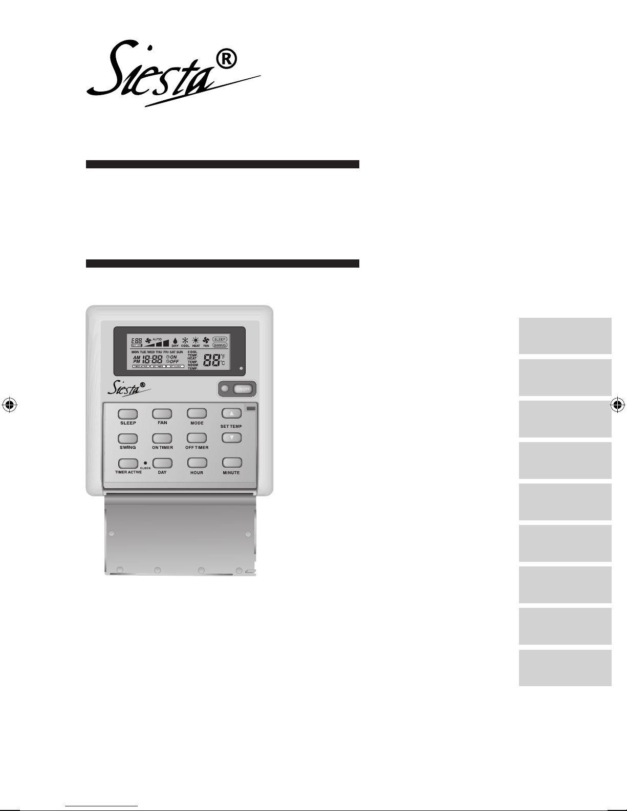
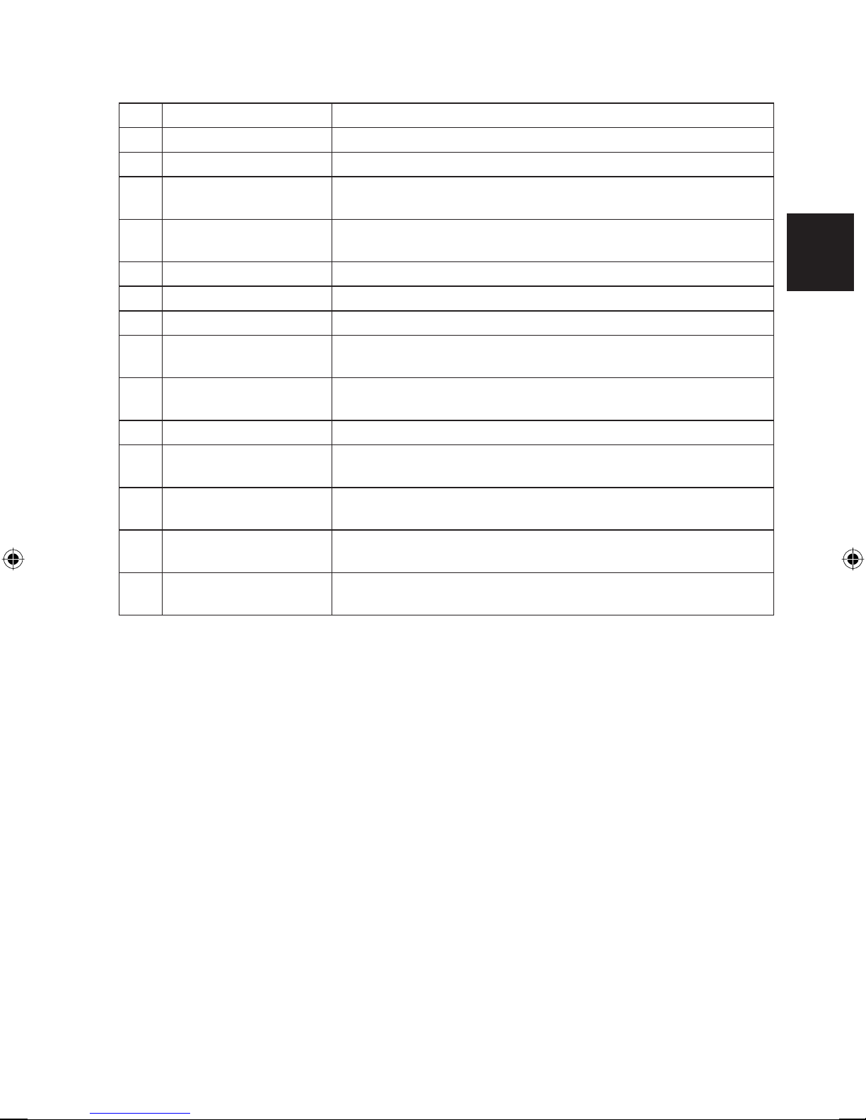
1.0 OPERATING GUIDE
There are all together 14 keys on the ARCWA wired controller.
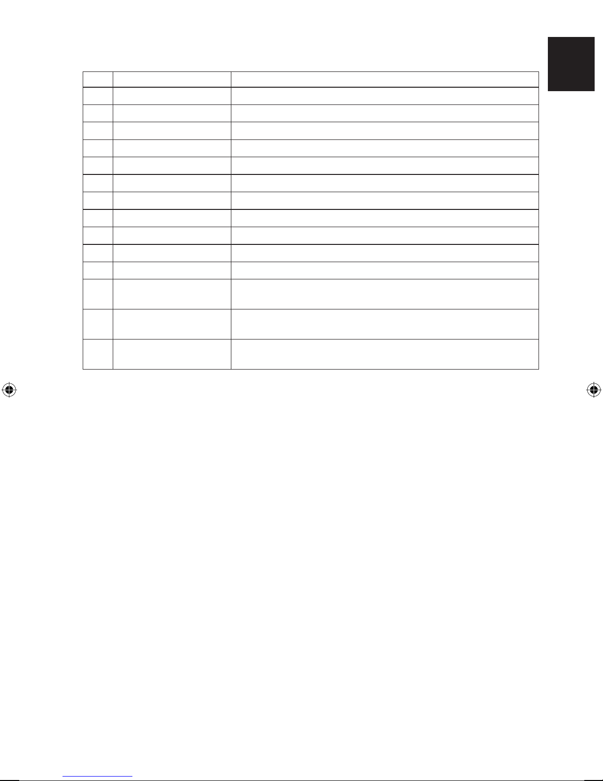
No KEY FUNCTION
1. ON/OFF
2. SLEEP
3. FAN
4. MODE
5. SET TEMP UP
6. SET TEMP DOWN
7. SWING
8. ON TIMER
9. OFF TIMER
10. TIMER ACTIVE
11. CLOCK
12. DAY
On/Off the unit with overriding all the timer settings
Activate/deactivate Sleep function
Select Fan speeds control (Auto/High/Med/Low)
Select operating Modes control (Cool/Heat/Dry/Fan)
Increase set temperature in °C or °F
Decrease set temperature in °C or °F
Activate/deactivate Swing control.
Enable/disable the Event 1, 2 and 3 ON TIMER setting mode
Enable/disable the Event 1, 2 and 3 OFF TIMER setting mode
Activate/deactivate all set timers
Enable/disable the Real Time Clock (RTC) setting mode
a) Select the day for RTC or timer setting
b) Enable/disable FAN Key lock
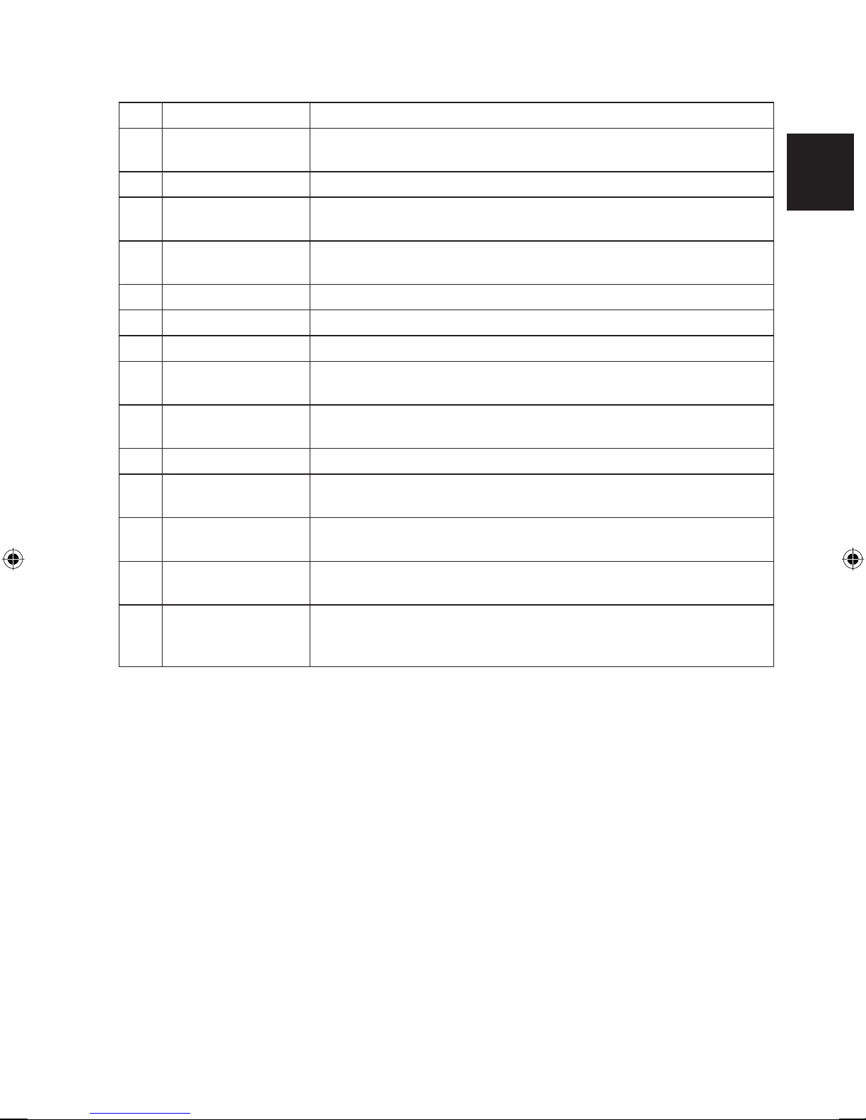
13. HOUR
a) Select the hour for RTC or timer settings
b) Set Override function for 1, 2 or 4 hours
14. MINUTE
a) Select the minute for RTC or timer settings
b) Enable/disable key lock
ENGLISH
Original Instruction
Note : Override Function
Press the HOUR key once will activate the override function for 1 hour. An indicator “H1” will show
on the top left corner of the LCD. Press the same key again will increase the setting to 2 hours. An
indicator “H2” will be shown. Press the 3rd times increase the setting to 4 hours. An indicator “H4”
will be shown. Subsequent press will deactivate the override function.
When the Override function is activated, all the timers will bypassed and turn ON the unit for a fi x
periods of 1 hour, 2 hours or 4 hours depends on the selection, after which it will turned off.
1

1.1 ON/OFF Button
Starting Operation:
•
When the unit is turned off, press the ON/OFF button.
The operation LED lights and the unit is turned on.
Stopping Operation:
•
When the unit is turned on, press the ON/OFF button. The operation LED is extinguished
and control are turned off.
1.2 SLEEP Button
Press SLEEP button to activate the sleep mode or energy saving mode.
1.3 FAN Button
Press FAN button to select AUTO, HIGH, MEDIUM or LOW fan speed.
1.4 MODE Button
Press the MODE button to switch operation from COOL, HEAT, DRY, FAN.
Check the display to see in which mode the control is set.
1.5 ‘▲’ or ‘▼’ Set Temperature Button
Press the temperature button and set the temperature of your choice. By pressing the ‘▲’ or
‘▼’ button once, temperature changes by 1°C [or 1°F].
Temperature can be set within the range 16°C~30°C (61°F~86°F).
During fan mode, temperature cannot be set.
If pressing ‘▲’ and ‘▼’ together, the unit of temperature will change from °C to °F and vice-versa.
1.6 SWING button
Press SWING button to activate the air sweep function.
1.7 Time Setting
i) Set Real Time Clock Setting
Press CLOCK key one time will activate RTC setting mode. Pressing the same key again
will disable RTC setting mode.
Under RTC setting mode, “SET CLOCK” will be shown on LCD and it will blink at 0.5 sec
interval. The RTC and Day setting can be changed by pressing DAY key, HOUR key or
MINUTE key. If there is no further time related (DAY, HOUR and MINUTE) key is pressed
for 15 sec, the unit will quit from the CLOCK setting mode.
ii) 7-Day Programmable Timers
The unit has 3 event functions, each event has an ON TIMER and an OFF TIMER.
Press the timer key (ON TIMER or OFF TIMER) will enable Event 1 timer setting mode.
Press the same key again will enable Event 2 timer setting mode. Press the 3rd times will
enable the Event 3 (Event handset) timer- setting mode. Subsequent key pressed the unit
will quit from timer setting mode.
All timers are event triggered timers and can be overridden by the ON/OFF button and
Override function.
2

iii) Set Event 1 and Event 2 Timers
Under timer setting mode, “SET TIMER” will be shown on LCD and blink at 0.5 sec interval.
For Event 1 Timer setting, ‘
displayed on the top left corner of the LCD. ‘ ON’ or ‘ OFF’ indication and digit “2” will
be displayed during Event 2 timer setting. The timer setting can be changed thru pressing
the DAY key, HOUR key or MINUTE key. If there is no further time related (DAY, HOUR
and MINUTE) key is pressed, the unit will quit from the timer setting mode.
iv) Set Event 3 Timer via remote control (Optional)
This timer can be controlled separately thru remote control as well as ON TIMER or OFF
TIMER keys. Timer 3 can be set like timers 1 and 2 like above except the DAY setting is
not provided as this timer setting is valid everyday. An indicator “3” will display during the
Event 3 timer setting mode. ‘
timer setting. If there is no futher time related (DAY, HOUR and MINUTE) key is pressed,
the unit will quit from the timer setting mode.
The ON/OFF timer setting received from remote control will override the Event 3 timer
setting from the unit.
ON’ or ‘ OFF’ indication will appear and digit “1” will be
ON’ or ‘ OFF’ will blink at 0.5 sec interval during the
1.8 Activating and canceling timers
These timers will not triggered if the timer is not active. To activate the timers, press the TIMER
ACTIVE key unit “TIMER ACTIVE” appears on LCD. This symbol is to indicate Event 1, Event
2 and/or Event 3 timers are active. Pressing the same steps will deactivate the timers and
“TIMER ACTIVE” symbol will disappear.
Another method to cancel the timers setting is changed all the hour setting of the timers to
null one by one. When the setting is null, the LCD display --:--, then this respective timer will
be disable.
ENGLISH
1.9 Key Lock
These key lock function to inhibit any setting change. Press the MINUTE key 3 times
consecutively will activate key lock function, “KEYLOCK” will be shown on LCD. Upon all
the keys are locked, only ON/OFF key and MINUTE key can be pressed. To cancel the key
lock function, press the MINUTE key 3 times consecutively, the word “KEYLOCK” will be
disappeared.
1.10 Fan Lock
When the DAY key is press 3 times consecutively within 1.5 sec, the fan symbol (shown
above) will disappear and fan key will be inhibit from pressing. Press the DAY key 3 times to
cancel the fan lock function.
1.11 Battery Backup
Battery backup is used to retain the RTC and 7-days programmable timer settings during
power down. For unit without battery backup, the default setting will be 12:00 am the timer
clear during power up.
3

2.0 INSTALLATION OF LCD REMOTE CONTROLLER
2.1 Accessories
The following accessories are included together with this manual. If any part is missing, contact
your dealer immediately.
1
Remote controller
2
Wooden screw 4.1 x 16 (2 pieces) & machine screw (2 pieces)
3
Instruction manual
4
Battery
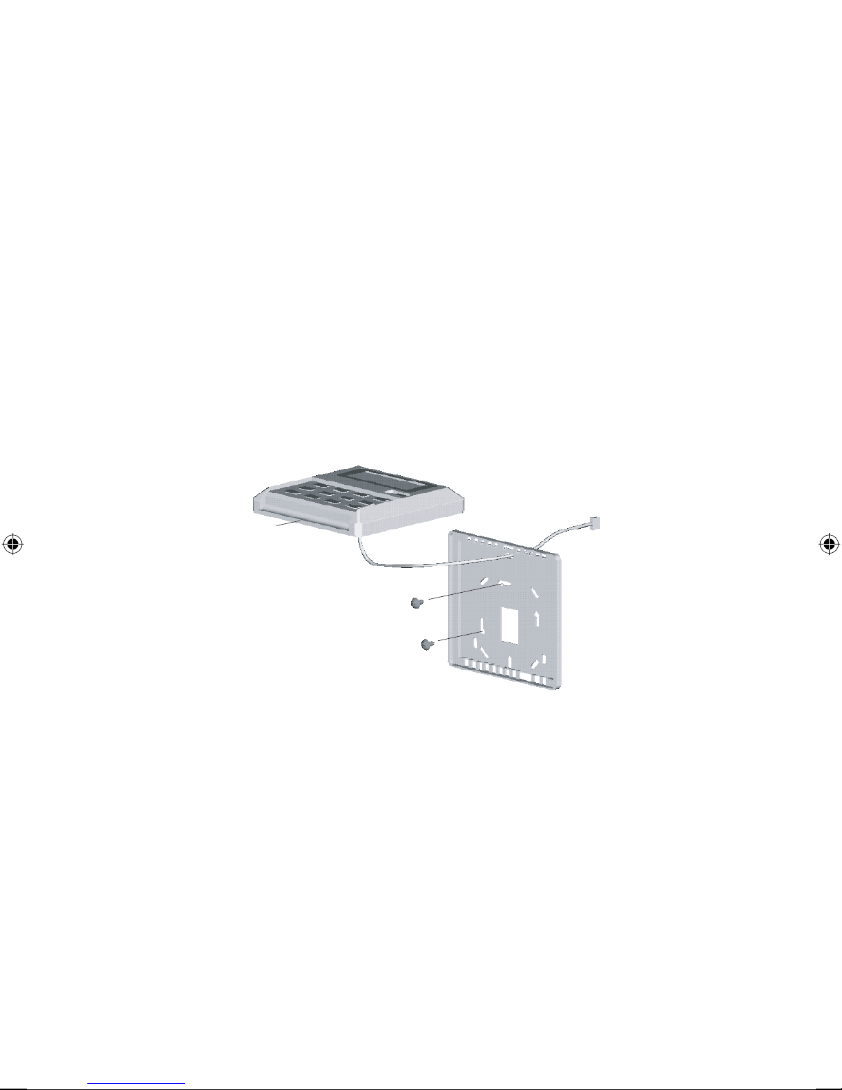
2.2 Step-by-step guide
i) First, open up the casing of the LCD remote controller into its top and bottom case using a
screwdriver. To do this, insert the screwdriver into the lower slot and slide it in the outward
direction.
ii) Fix the bottom case onto the wall with the 2 wooden screws provided.
Then, insert the 4-pin connection wires (from main board) through the slot on the upper
center of the case as shown below.
iii) To select cooling only model or heatpump model, some adjustment required in the shunt
jumper setting.
iv) Fasten back the top and bottom case into place. Hook the two upper claws into their
respective slots and snap the lower part shut.
LCD Remote
(Top case)
Lower slot
for opening LCD casing
2 x Wooden
Connection
wires
screw
LCD Remote
(Bottom case)
4

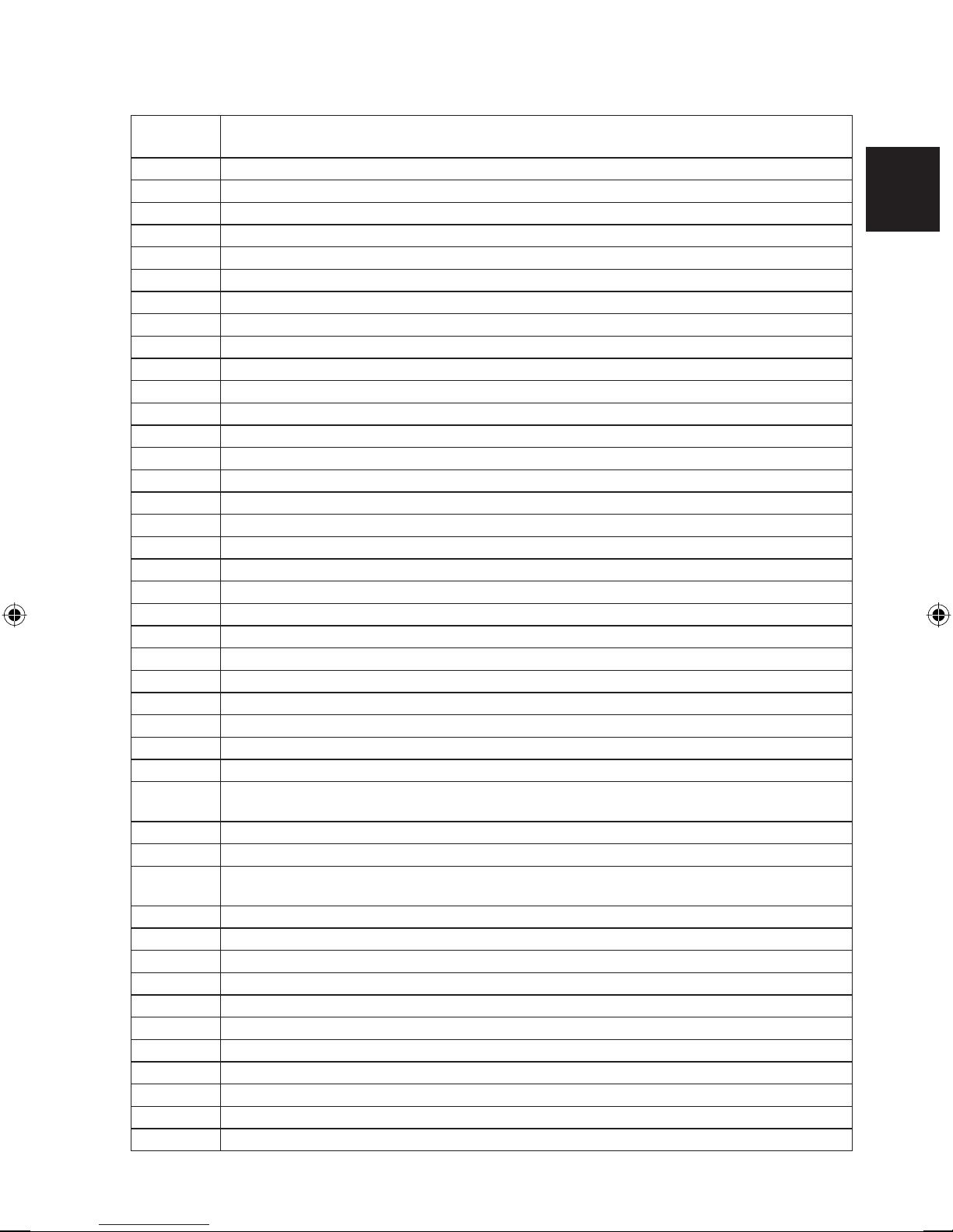
3.0 FAULT DIAGNOSIS (For Inverter only)
If there is any abnormal condition detected, ARCWA wired controller will blink the error code.
ERROR CODE MEANING
00 NORMAL
A1 INDOOR PCB ERROR
A3 DRAIN PUMP ABNORMAL
A5 ANTIFREEZE (COOLING)/HEAT EXCHANGER OVERHEAT (HEATING)
A6 INDOOR FAN MOTOR ABNORMAL
AH ELECTRICAL AIR CLEANER ABNORMAL
C4 INDOOR HEAT EXCHANGER (1) THERMISTOR SHORT/OPEN
C5 INDOOR HEAT EXCHANGER (2) THERMISTOR SHORT/OPEN
C7 LOUVER LIMIT SWITCH ERROR
C9 INDOOR ROOM THERMISTOR SHORT/OPEN
E1 OUTDOOR PCB ERROR
E3 HIGH PRESSURE PROTECTION
E4 LOW PRESSURE PROTECTION
E5 COMPRESSOR MOTOR LOCK/COMPRESSOR OVERLOADED
E6 COMPRESSOR START-UP ERROR
E7 OUTDOOR DC FAN MOTOR LOCK
E8 AC INPUT OVER CURRENT
E9 EXV ERROR
EA 4 WAY VALVE ERROR
F3 DISCHARGE PIPE OVERHEAT
F6 HEAT EXCHANGER OVERHEAT
HO COMPRESSOR SENSOR SYSTEM ERROR
H3 HIGH PRESSURE SWITCH ERROR
H6 COMPRESSOR FEEDBACK DETECTION ERROR
H7 FAN MOTOR OVERLOADED/OVERCURRENT/SENSOR ABNORMAL
H8 AC CURRENT SENSOR ERROR
H9 OUTDOOR AIR THERMISTOR SHORT/OPEN
J1 PRESSURE SENSOR ERROR
J3
COMPRESSOR DISCHARGE PIPE THERMISTOR SHORT/OPEN/MISPLACED
J5 SUCTION PIPE THERMISTOR SHORT/OPEN
J6 OUTDOOR HEAT EXCHANGER THERMISTOR SHORT/OPEN
J7 SUBCOOLING HEAT EXCHANGER THERMISTOR SHORT/OPEN
J8 LIQUID PIPE THERMISTOR SHORT/OPEN
J9 GAS PIPE THERMISTOR SHORT/OPEN
L1 INVERTER OUTDOOR PCB ERROR
L3 OUTDOOR CONTROL BOX OVERHEAT
L4 HEAT SINK OVERHEAT
L5 IPM ERROR/IGBT ERROR
L8 INVERTER COMPRESSOR OVERCURRENT
L9 COMPRESSOR OVERCURRENT PREVENTION
LC
COMMUNICATION ERROR (OUTDOOR CONTROL PCB AND INVERTER PCB)
P1 OPEN PHASE OR VOLTAGE UNBALANCE
P4 HEAT SINK THERMISTOR SHORT/OPEN
5
ENGLISH

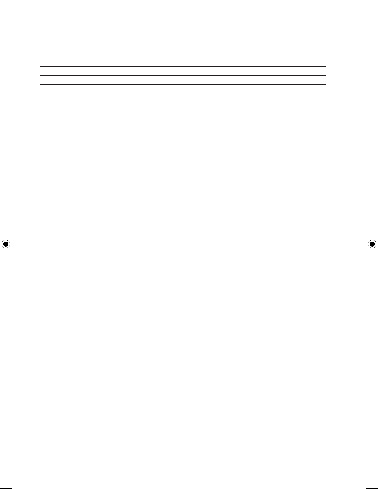
ERROR CODE MEANING
PJ CAPACITY SETTING ERROR
U0 INSUFFICIENT GAS
U2 DC VOLTAGE OUT OF RANGE
U4 COMMUNICATION ERROR
U7 COMMUNICATION ERROR (OUTDOOR CONTROL PCB AND IPM PCB)
UA INSTALLATION ERROR
UF
PIPING & WIRING INSTALLATION MISMATCH/WRONG WIRING/INSUFFICIENT GAS
UH ANTIFREEZE (OTHER ROOMS)
6
1.0 MODE D’EMPLOI
Il y a 14 touches en tout sur la télécommande câblée ARCWA.
No TOUCHE FONCTION
1. ON/OFF
2. SLEEP
3. FAN
4. MODE
5. SET TEMP UP
6. SET TEMP DOWN
7. SWING
8. ON TIMER
9. OFF TIMER
10. TIMER ACTIVE
11. CLOCK
12. DAY
Appuyez sur la touche On/Off de l’unité pour annuler tous les
réglage de la minuterie
Activez/désactivez la fonction Sommeil
Sélectionnez la commande des vitesses du ventilateur
(Auto/High/Med/Low)
Sélectionnez la commande des modes de fonctionnement
(Cool/Heat/Dry/Fan)
Augmentez la température réglée en °C ou en °F
Réduisez la température réglée en °C ou en °F
Activez/désactivez la commande d’oscillation.
Activez/désactivez le mode de réglage MINUTERIE DE MISE EN
MARCHE, événements 1, 2 et 3
Activez/désactivez le mode de réglage MINUTERIE DE MISE EN
ARRÊT, événements 1, 2 et 3
Activez/désactivez toutes les minuteries réglées
Activez/désactivez le mode de réglage de l’horloge temps réel
(HTR)
a) Sélectionnez le jour pour le réglage de l’HTR ou de la minuterie
b) Activez/désactiver le verrouillage de la touche FAN (ventilateur)
FRANÇAIS
Traduction des instructions d’origine
13. HOUR
a) Sélectionnez l’heure pour le réglage de l’HTR ou de la minuterie
b) Réglez la fonction prioritaire sur 1, 2 ou 4 heures
14. MINUTE
a) Sélectionnez la minute pour le réglage de l’HTR ou de la
minuterie
b) Activez/désactiver le verrouillage de touches
Remarque : Fonction prioritaire
Frappez la touche HOUR une fois pour activer la fonction prioritaire pendant une heure. Un indicateur
“H1” s’allumera dans l’angle supérieur gauche de l’écran LCD. Appuyez de nouveau sur la même
touche pour augmenter le réglage à 2 heures. Un indicateur “H2” s’allumera. Appuyer une troisième
fois augmente le réglage à 4 heures. Un indicateur “H4” s’allumera. Appuyer de nouveau désactivera
la fonction prioritaire.
Lorsque la fonction prioritaire est activée, toutes les minuteries sont contournées ; allumer l’unité pour
une période fi xe d’une, deux ou quatre heures dépend de la sélection faite. L’unité s’éteint ensuite.
7

1.1 Bouton de mise en ON/OFF
Mise en marche :
•
Lorsque l’unité est éteinte, appuyez sur la bouton ON/OFF.
Le lumineux LED s’allume et l’unité se met en marche.
Mise en arrêt :
•
Lorsque l’unité est en marche, appuyez sur la bouton ON/OFF. Le lumineux LED et les
contrôles s’éteignent.
1.2 Bouton de Nuit SLEEP
Appuyez sur le bouton de nuit SLEEP pour activer le mode de nuit et d’économie d’énergie.
1.3 Bouton de Nuit FAN
Appuyez sur le bouton FAN pour régler les vitesses de ventilation sur AUTO (AUTO),HIGH
(RAPIDE), MEDIUM (MOYEN) ou LOW (LENT).
1.4 Bouton de MODE
Appuyez sur le bouton MODE pour alterner entre COOL (FROID), HEAT (CHAUD), DRY
(SEC), FAN (VENTILATION).
Vérifi ez l’affi chage pour voir sur quel mode est réglée l’unité.
1.5 Le Bouton du Réglage de la Température ‘▲’ ou ‘▼’
Appuyez sur le bouton de la température et programmez la température de votre choix. En
appuyant une fois sur l’un des boutons ‘▲’ ou ‘▼’, la température varie de 1°C [ou de 1°F].
La température peut être programmée de 16°C à 30°C (61°F à 86°F).
Pendant le mode de ventilation, la température peut aussi être programmée.
Si vous appuyez sur les deux boutons ‘▲’ et ‘▼’ en même temps, l’unité de température passe
des °C aux °F ou vice-versa.
1.6 Bouton du Mouvement Oscillatoire SWING
Appuyez sur le bouton SWING pour actionner la fonction de ventilation oscillatoire.
1.7 Réglage de L’horloge
i) Fixez le réglage de l’horloge temps réel
Pressez la touche CLOCK une fois pour activer le mode de réglage HTR. Appuyez de
nouveau sur la même touche pour désactiver le mode de réglage HTR.
Dans le mode de réglage HTR, "SET CLOCK" (RÉGLEZ HORLOGE) s’affi chera sur l’écran
LCD et clignotera à 0,5 sec. d’intervalle. Le réglage HTR et de jour sont modifi ables en
appuyant sur les touches DAY, HOUR ou MINUTE. Si aucune autre touche de réglage de
l’horloge (DAY, HOUR et MINUTE) n’est pressée pendant 15 sec., l’unité sort du mode
de réglage HORLOGE.
ii) Minuteries programmables sur 7 jours
L’unité est dotée de 3 fonctions d’événement, chacune offrant une minuterie de mise
en marche (ON TIMER) et une de mise en arrêt (OFF TIMER). Pressez la touche de
minuterie (ON TIMER ou OFF TIMER) pour activer le mode de réglage de la minuterie de
l’événement 1. Appuyez de nouveau sur la même touche pour activer le mode de réglage
de la minuterie de l’événement 2. Appuyez pour la troisième fois pour activer le mode de
réglage de la minuterie de l’événement 3 (clavier d’événements). Appuyer de nouveau
sur une touche de l’unité fait sortir du mode de réglage de la minuterie.
Toutes les minuteries sont des minuteries déclenchées par des événements et peuvent
être annulées par la touche ON/OFF et la fonction prioritaire.
8
iii) Fixez les minuteries des événements 1 et 2
Dans le mode de réglage de la minuterie, “SET TIMER” s’affi chera sur l’écran LCD
et clignotera à 0,5 sec. d’intervalle. Lors du réglage de la minuterie de l’événement 1,
l’indicateur ‘ ON’ ou ‘ OFF’ apparaîtra, et le chiffre “1” s’affi chera dans l’angle supérieur
gauche de l’écran LCD. L’indicateur ‘ ON’ ou ‘ OFF’ et le chiffre “2” s’affi cheront
pendant le réglage de la minuterie de l’événement 2. Le réglage du minuteur peut être
modifi é en appuyant sur la touche DAY, la touche HOUR ou la touche MINUTE. Si aucune
autre touche de réglage de l’horloge (DAY, HOUR et MINUTE) n’est pressée, l’unité sortira
du mode de réglage de la minuterie.
iv) Fixez la minuterie de l’événement 3 par le biais de la télécommande (en option)
Ce minuteur peut être commandé séparément via la télécommande ainsi que via les
touches ON TIMER ou OFF TIMER. La minuterie 3 peut être réglée comme les minuteries
1 et 2 ci-dessus, sauf pour le réglage JOUR qui n’est pas fourni, car cette minuterie
s’applique tous les jours. Un indicateur “3” s’affi chera pendant le mode de réglage de la
minuterie de l’événement 3. ‘
le réglage de la minuterie. Si aucune autre touche de réglage de l’horloge (DAY, HOUR
et MINUTE) n’est pressée, l’unité sortira du mode de réglage de la minuterie.
Le réglage de la minuterie ON/OFF reçu de la télécommande annulera le réglage de la
minuterie de l’événement 3 de l’unité.
ON’ ou ‘ OFF’ clignotera à 0,5 sec. d’intervalle pendant
1.8 Activation et annulation des minuteries
Ces minuteries ne se déclencheront pas à moins d’être activées. Pour activer les minuteries,
appuyez sur la touche “TIMER ACTIVE” ; l’indicateur correspondant s’affi chera sur l’écran
LCD de l’unité. Ce symbole sert à indiquer que les minuteries d’événement 1, 2 ou 3 sont
actives. Répéter les mêmes étapes désactivera les minuteries, et le symbole “TIMER ACTIVE”
disparaîtra.
Une autre méthode pour annuler le réglage des minuteries consiste à mettre à zéro tous leurs
réglages d’heure, un par un. Une fois le réglage sur zéro, l’écran LCD affi che --:--. La minuterie
correspondante sera alors désactivée.
FRANÇAIS
1.9 Verrouillage de touches
La fonction de verrouillage de touches sert à empêcher tout changement de réglage. Appuyez
sur la touche MINUTE 3 fois de suite pour activer la fonction de verrouillage de touches ;
“KEYLOCK” s’affi che sur l’écran LCD. Dès que la totalité des touches est verrouillée, seules les
touches ON/OFF et MINUTE peuvent être pressées. Pour annuler la fonction de verrouillage
de touches, appuyez sur la touche MINUTE 3 fois, le mot “KEYLOCK” disparaît.
1.10 Verrouillage du ventilateur
Lorsque la touche DAY est pressée 3 fois de suite dans la première seconde et demie,
le symbole du ventilateur (illustration ci-dessus) disparaît et le verrouillage du ventilateur
empêche d’appuyer sur la touche. Appuyez sur la touche DAY 3 fois pour annuler la fonction
de verrouillage du ventilateur.
1.11 Batterie de secours
La batterie de secours sert à conserver l’HTR et les réglages de minuterie programmable sur
7 jours quand l’alimentation est coupée. Pour les unités sans batterie de secours, le réglage
par défaut est de 12:00, et la minuterie est effacée au démarrage.
9
2.0 INSTALLATION DE LA TÉLÉCOMMANDE LCD
2.1 Accessoires
Les accessoires suivants sont compris avec ce manuel. S’il manque des éléments, veuillez
contacter votre concessionnaire immédiatement.
1
Télécommande
2
Vis à bois 4,1 x 16 (2 vis) & Vis de l’unité (2 vis)
3
Manuel d’utilisation
4
Pile
2.2 Guide Détaillé
i) D’abord, ouvrez le boîtier de la télécommande LCD en séparant la partie supérieure de
la partie inférieure. Pour ce faire, utilisez un tournevis que vous insérez dans la fente et
faites glisser vers le haut.
ii) Fixez la partie inférieure du boîtier sur le mur avec les 2 vis à bois fournies.
Ensuite, insérez les fi ls de connexion à 4 broches (de la carte principale) à travers la fente
sur la partie centrale supérieure de l’enveloppe, comme dans l’illustration.
iii) Pour sélectionner le modèle de refroidissement ou de thermopompe, certains réglages
sont nécessaires au niveau de l’interrupteur à positions multiples.
iv) Rattachez la partie inférieure et supérieure du boîtier. Accrochez les deux pattes dans
leur fente respective et fermez la partie inférieure.
Télécommande LCD
(boîtier inférieur)
Fente inférieure
pour ouvrir le boîtier LCD
Fils de
raccordement
2 x Vis à bois
Télécommande LCD
(boîtier supérieur)
10
3.0 DIAGNOSTIC DES ERREURS (Pour Modèle à Inverseur Seulement)
Si une condition anormale est détectée, le code d’erreur clignote sur la télécommande fi laire ARCWA.
CODE
D’ERREUR
SIGNIFICATION
00 NORMAL
A1 ERREUR PCB DANS LA SECTION INTÉRIEURE
A3 ANOMALIE DE LA POMPE DE VIDANGE
A5
ANTIGEL (REFROIDISSEMENT) / ÉCHANGEUR DE CHALEUR DE SURCHAUFFE (CHAUFFAGE)
A6 ANOMALIE SUR LE VENTILATEUR D’INTÉRIEUR
AH ANOMALIE DU FILTRE À AIR ÉLECTRIQUE
C4
C5
THERMISTOR DE L'ÉCHANGEUR THERMIQUE INTÉRIEUR (1) EN COURT-CIRCUIT/OUVERT
THERMISTOR DE L'ÉCHANGEUR THERMIQUE INTÉRIEUR (2) EN COURT-CIRCUIT/OUVERT
C7 ERREUR DE L’INTERRUPTEUR DE LIMITE D’AILETTE
C9 COURT-CIRCUIT/OUVERTURE DANS LE THERMISTOR DE PIÈCE INTÉRIEURE
E1 ERREUR DE CARTE EXTÉRIEURE
E3 PROTECTION HAUTE PRESSION
E4 PROTECTION BASSE PRESSION
E5 VERROU DU MOTEUR DU COMPRESSEUR /COMPRESSEUR SURCHARGÉ
E6 ERREUR DE DÉMARRAGE DU COMPRESSEUR
E7 VERROU DU MOTEUR DE VENTILATEUR CC EXTÉRIEUR
E8 SURINTENSITÉ D’ENTRÉE CA
E9 ERREUR EXV
EA ERREUR DE VANNE À 4 VOIES
F3 TUYAUTERIE DE VIDANGE DE SURCHAUFFE
F6 ÉCHANGEUR DE CHALEUR DE SURCHAUFFE
HO ERREUR DU SYSTÈME DE CAPTEUR DU COMPRESSEUR
H3 ERREUR DE L’INTERRUPTEUR HAUTE PRESSION
H6 ERREUR DE DÉTECTION DE L’ALIMENTATION DU COMPRESSEUR
H7 SURCHARGE/SURINTENSITÉ DU MOTEUR DU VENTILATEUR/ANOMALIE DU CAPTEUR
H8 ERREUR DU CAPTEUR DE COURANT CA
H9 THERMISTANCE À AIR EXTÉRIEUR EN COURT-CIRCUIT/OUVERT
J1 ERREUR DU CAPTEUR DE PRESSION
J3 THERMISTANCE DE LA TUYAUTERIE DE VIDANGE DU COMPRESSEUR EN COURT-
CIRCUIT/OUVERTE/ MAL POSITIONNÉE
J5 COURT-CIRCUIT/OUVERTURE DANS LE THERMISTOR DU TUYAU D’ASPIRATION
J6
J7
THERMISTANCE D’ÉCHANGEUR DE CHALEUR EXTÉRIEUR EN COURT-CIRCUIT/OUVERT
COURT-CIRCUIT/OUVERTURE DANS LE THERMISTOR DE L’ÉCHANGEUR THERMIQUE
DE SOUS- REFROIDISSEMENT
J8 THERMISTANCE DE LA TUYAUTERIE DU LIQUIDE EN COURT-CIRCUIT/OUVERTE
J9 THERMISTANCE DE LA TUYAUTERIE DE GAZ EN COURT-CIRCUIT/OUVERTE
L1 ERREUR PCB EXTÉRIEURE DE L’INVERSEUR
L3 BOÎTIER DE COMMANDE EXTÉRIEUR DE SURCHAUFFE
L4 DISSIPATEUR THERMIQUE DE SURCHAUFFE
L5 ERREUR IPM /ERREUR IGBT
L8 SURINTENSITÉ DU COMPRESSEUR DE L’INVERSEUR
L9 PRÉVENTION DE SURINTENSITÉ DU COMPRESSEUR
LC
ERREUR DE COMMUNICATION (PCB DE LA COMMANDE EXTÉRIEURE ET PCB DE INVERSEUR)
P1 PHASE OUVERTE OU DÉSÉQUILIBRE DE TENSION
P4 THERMISTANCE DE DISSIPATEUR DE CHALEUR EN COURT-CIRCUIT/OUVERT
FRANÇAIS
11
CODE
D’ERREUR
PJ
U0
U2
U4
U7
UA
UF
UH
SIGNIFICATION
ERREUR DE RÉGLAGE DE LA CAPACITÉ
INSUFFISANCE DE GAZ
TENSION CC HORS PLAGE
ERREUR DE COMMUNICATION
ERREUR DE COMMUNICATION (CARTE DE COMMANDE ET CARTE IPM)
ERREUR D’INSTALLATION
MAUVAISE CORRESPONDANCE DANS L’INSTALLATION DU CÂBLAGE ET DE LA
TUYAUTERIE/MAUVAIS CÂBLAGE/INSUFFISANCE EN GAZ
ANTIGEL (AUTRES PIÈCES)
12
1.0 BETRIEBSANWEISUNG
Die drahtgebundenen ARCWA-Steuerung hat insgesamt 14 Tasten.
No TASTE FUNKTION
1. ON/OFF
An/Aus des Geräts mit Löschung aller Timer-Funktionen
2. SLEEP
3. FAN
4. MODE
5. SET TEMP UP
6. SET TEMP DOWN
7. SWING
8. ON TIMER
9. OFF TIMER
10. TIMER ACTIVE
11. CLOCK
12. DAY
13. HOUR
Aktivierung/Deaktivierung der Schlaffunktion
Auswahl der Steuerung für Ventilatorgeschwindigkeiten
(Auto/Hoch/Mittel/Niedrig)
Auswahl der Steuerung für Betriebsmodi
(Kühlen/Heizen/Trocknen/Ventilator)
Eingestellte Temperatur in °C oder °F erhöhen
Eingestellte Temperatur in °C oder °F senken
Pendelsteuerung aktivieren/deaktivieren
Einschalten/Ausschalten des ON TIMER-Einstellungsmodus
von Ereignis 1, 2 und 3
Einschalten/Ausschalten der OFF TIMER-Einstellungsmodus
von Ereignis 1, 2 und 3
Alle eingestellten Timer aktivieren/deaktivieren
Einschalten/Ausschalten des Einstellungsmodus der reellen Zeituhr
(RTC)
a) Den Tag für RTC oder Timereinstellung auswählen
b) Einschalten/Ausschalten der FAN-Tastensperre
a) Die Stunde für RTC oder Timereinstellungen auswählen
b) Override-Funktion für 1, 2 oder 4 Stunden einstellen
DEUTSCH
Übersetzung der Original-Anleitungen
14. MINUTE
a) Die Minute für RTC oder Timereinstellungen auswählen
b) Tastensperre einschalten/ausschalten
Anmerkung: Override-Funktion
Drücken Sie ein Mal die HOUR-Taste, dies aktiviert die Override-Funktion für 1 Stunde. Die Anzeige
“H1” wird in der oberen linken Ecke des LCD angezeigt. Drücken Sie die Taste erneut und die
Einstellung steigt auf 2 Stunden an. Es wird die Anzeige “H2” angezeigt. Wenn Sie die Taste zum
dritten Mal drücken, werden 4 Stunden eingestellt. Es wird die Anzeige “H4” angezeigt. Ein weiteres
Drücken deaktiviert die Override-Funktion.
Bei aktivierter Override-Funktion werden alle Timer umgangen und das Gerät wird für einen
festgelegten Zeitraum von 1 Stunde, 2 Stunden oder 4 Stunden, je nach Auswahl, angeschaltet.
Nach Ablauf dieser Zeit wird das Gerät automatisch abgeschaltet.
13

1.1 ON/OFF Taste
Beginn des Betriebs:
Ist das Gerät ausgeschaltet, die ON/OFF Taste betätigen.
Betriebs-LED leuchtet auf, das Gerät ist eingeschaltet.
Abschalten des Betriebs:
Ist das Gerät eingeschaltet, die ON/OFF Taste betätigen. Betriebs-LED erlischt und das
Gerät ist ausgeschaltet.
1.2 SLEEP-Taste
Zum Aktivieren des Schlaf- oder Energiespar-Betriebs die SLEEP-Taste betätigen.
1.3 FAN-Taste
Zur Auswahl der AUTO (AUTO), HIGH (HOCH), MEDIUM (MITTEL) oder LOW (NIEDRIG)
– Kühlgebläsedrehzahl die FAN-Taste betätigen.
1.4 MODE-Taste
Die MODE Taste betätigen, um den Betrieb von COOL (KÜHL), HEAT (WARM), DRY
(TROCKEN) oder FAN (GEBLÄSE) zu schalten.
Die Anzeige zeigt die eingestellte Betriebsart an.
1.5 ‘▲’ oder ‘▼’ Temperatur-Einstell-Taste
Die Temperaturtaste betätigen und die gewünschte Temperatur einstellen. Bei einmaligem
Betätigen der ‘▲’ oder ‘▼’ Taste ändert sich die Temperatur jeweils um 1°C (oder 1°F).
Die Temperatur kann im Bereich von 16°C~30°C (61°F~86°F).
Bei Kühlgebläse-Betrieb kann die Temperatur eingestellt werden.
Werden die ‘▲’ und ‘▼’ Tasten zusammen betätigt, ändert sich die Temperaturanzeige von
°C auf °F, und umgekehrt.
1.6 SWING-Taste
Zum Aktivieren der Luftpendelfunktion die SWING-Taste betätigen.
1.7 Zeiteinstellung
i) Einstellungen der reellen Zeituhr einrichten
Drücken Sie die CLOCK-Taste ein Mal, um den RTC-Einstellungsmodus zu aktivieren.
Durch erneutes Drücken der Taste wird der RTC-Einstellungsmodus ausgeschaltet.
Im RTC-Einstellungsmodus wird “SET CLOCK” auf dem LCD gezeigt und blinkt in
Intervallen zu 0,5 Sekunden. Die Einstellungen für RTC und DAY können geändert werden,
indem Sie die Tasten DAY, HOUR oder MINUTE drücken. Falls Sie 15 Sekunden lang
keine weitere mit, Zeit in Beziehung stehende, Taste drücken (DAY, HOUR, oder MINUTE),
verlässt das Gerät automatisch den Einstellungsmodus CLOCK.
ii) Für 7 Tage programmierbare Timer
Das Gerät hat 3 Ereignisfunktionen, jedes Ereignis hat jeweils einen ON TIMER und einen
OFF TIMER. Durch Drücken der Timer-Taste (ON TIMER oder OFF TIMER) wird der
Timereinstellungsmodus für Ereignis 1 eingeschaltet. Durch erneutes Drücken derselben
Taste wird Ereignis 2 eingeschaltet. Durch nochmaliges Drücken derselben Taste wird der
Timereinstellungsmodus für Ereignis 3 (Ereignis Handapparat) eingeschaltet. Durch jedes
weitere Drücken der Taste wird der Timereinstellungsmodus abgeschaltet.
Alle Timer sind durch Ereignisse ausgelöste Timer und können durch die ON/OFF-Taste
und die Override-Funktion deaktiviert werden.
14

iii) Stellen Sie die Timer für Ereignis 1 und Ereignis 2 ein
Im Timereinstellungsmodus wird “SET TIMER” im LCD angezeigt und blinkt in Intervallen
von 0,5 Sekunden. Bei Timereinstellung für Ereignis 1 erscheint ‘
und die Ziffer “1” wird in der linken oberen Ecke des LCD angezeigt. ‘ ON’ oder
‘ OFF’ und die Ziffer “2” werden während der Timereinstellung für Ereignis 2 angezeigt.
Die Einstellung des Timers kann durch Drücken der Taste DAY, HOUR oder MINUTE
geändert werden. Falls Sie 15 Sekunden lang keine weitere, mit Zeit in Beziehung
stehende, Taste drücken (DAY, HOUR, oder MINUTE), verlässt das Gerät automatisch
den Timereinstellungsmodus.
iv) Stellen Sie den Timer für Ereignis 3 über die Fernbedienung ein (Optional)
Dieser Timer kann getrennt sowohl durch die Fernbedienung, als auch durch die Tasten
ON TIMER oder OFF TIMER gesteuert werden. Timer 3 kann, wie bei Timer 1 und Timer
2 oben beschrieben, eingestellt werden; Ausnahme ist die Einstellung DAY. Diese ist nicht
verfügbar, da diese Timereinstellung jeden Tag gültig ist. Die Anzeige “3” wird während
des Timereinstellungsmodus für Ereignis 3 angezeigt. Während der Timereinstellung blinkt
ON’ oder ‘ OFF’ in Intervallen zu 0,5 Sekunden. Falls Sie 15 Sekunden lang keine
‘
weitere, mit Zeit in Beziehung stehende, Taste drücken (DAY, HOUR, oder MINUTE),
verlässt das Gerät automatisch den Timereinstellungsmodus.
Die Timereinstellung ON/OFF der Fernbedienung löscht die Timereinstellung für Ereignis
3 des Geräts.
ON’ oder ‘ OFF’
1.8 Aktivierung und Abbruch der Timer
Die Timer werden nicht ausgelöst, wenn der Timer nicht aktiv ist. Drücken Sie die Taste
TIMER ACTIVE, um die Timer zu aktivieren. Es erscheint dann “TIMER ACTIVE” auf dem
LCD. Durch dieses Symbol wird angezeigt, dass die Timer für Ereignis 1, Ereignis 2 und/oder
Ereignis 3 aktiv sind. Durch Drücken derselben Tasten werden die Timer deaktiviert und
“TIMER ACTIVE” verschwindet.
Eine andere Möglichkeit, die Timereinstellung abzubrechen, ist, alle Stundeneinstellungen der
Timer eine nach der anderen auf Null zu stellen. Sobald die Einstellung auf Null ist, zeigt die
LCD --:--, dann ist der entsprechende Timer deaktiviert.
DEUTSCH
1.9 Tastensperre
Die Tastensperrfunktion sperrt alle Änderungen der Einstellungen. Drücken Sie drei Mal
nacheinander die MINUTE-Taste, um die Tastensperre zu aktivieren. Es erscheint “KEYLOCK”
im LCD. Wenn alle Tasten gesperrt sind, können nur die Tasten ON/OFF und MINUTE betätigt
werden. Drücken Sie drei Mal nacheinander die MINUTE-Taste, um die Tastensperre zu
deaktivieren. Es verschwindet “KEYLOCK”.
1.10 Ventilatorsperre
Wenn Sie die DAY-Taste innerhalb von 1,5 Sekunden drei Mal hintereinander drücken,
verschwindet das Ventilatorsymbol (siehe oben) und die Ventilatortaste wird gesperrt. Drücken
Sie die DAY-Taste drei Mal, um die Ventilatorsperre wieder aufzuheben.
1.11 Netzausfallschutz
Der Netzausfallschutz wird benötigt, um die RTC und die für 7 Tage programmierbaren
Timereinstellungen beizubehalten, während das Gerät abgeschaltet ist. Für Geräte ohne
Netzausfallschutz ist die Standardeinstellung 12:00 a.m., wenn das Gerät wieder angeschaltet
wird.
15

2.0 INSTALLIERUNG DER LCD-FERNBEDIENUNG
2.1 Zubehör
Folgendes Zubehör wird zusammen mit diesem Handbuch mitgeliefert. Sollte etwas fehlen,
wenden Sie sich bitte sogleich an Ihren Fachhändler.
1
Fernbedienung
2
Holzschrauben 4,1 x 16 (2 Stück) & Maschinenschrauben (2 Stück)
3
Gebrauchsanweisung
4
Batterie
2.2 Installierungsschritte
i) Das Oberteil des Gehäuses der LCD-Fernbedienung vom Unterteil abnehmen. Dabei
einen Schraubenzieher in den unteren Schlitz einführen und nach aussen ziehen
ii) Das Unterteil des Gehäuses mit den beiden Holzschrauben an der Wand befestigen.
Fügen Sie die 4-Pin-Verbindungsdrähte (von der Hauptplatine) durch den Schlitz oben in
der Mitte des Gehäuses, wie unten zu sehen, ein.
iii) Zur Auswahl von Kühlbetrieb oder Betrieb der Wärmepumpe ist die Einstellung des
Dip–Schalters nachzustellen.
iv) Ober- und Unterteil des Gehäuses wieder zusammenfügen. Dabei die beiden oberen
Haken in die zugehörigen Schlitze einpassen und das Unterteil anpressen.
LCD-Fernbedienung
(Gehäuseoberteil)
Unterer Schlitz zum
Öffnen des LCDGehäuses
2 x Holzschrauben
Verbindungsdrähte
LCD-Fernbedienung
(Gehäuseunterteil)
16

3.0 FEHLERBEHANDLUNG (Nur für Inverter)
Bei Erkennung eines Fehlerzustands blinkt der Fehlercode auf dem Kabelsteuerung ARCWA.
FEHLER-
MELDUNG
BEDEUTUNG
00 NORMAL
A1 LEITERPLATTENFEHLER DER INNENEINHEIT
A3 ABLAUFPUMPE ANOMAL
A5 FROSTSCHUTZ (KÜHLUNG)/WÄRMEAUSTAUSCHER ÜBERHITZT (HEIZUNG)
A6 INNENLÜFTER, MOTOR ANOMAL
AH FEHLER AN ELEKTRO-LUFTREINIGER
C4
C5
INNENRAUMWÄRMETAUSCHER (1) THERMISTOR, KURZSCHLUSS/UNTERBRECHUNG
INNENRAUMWÄRMETAUSCHER (2) THERMISTOR, KURZSCHLUSS/UNTERBRECHUNG
C7 FEHLER AN ENDSCHALTER DER LUFTKLAPPE
C9 INNENRAUMTHERMISTOR, KURZSCHLUSS/UNTERBRECHUNG
E1 AUSSEN-PBC-FEHLER
E3 HOCHDRUCKSCHUTZ
E4 NIEDERDRUCKSCHUTZ
E5 KOMPRESSORMOTOR VERRIEGELT/KOMPRESSOR ÜBERLASTET
E6 KOMPRESSOR-ANLAUFFEHLER
E7 DC-AUSSENVENTILATORMOTOR VERRIEGELT
E8 AC-EINGANGSSTROM ZU HOCH
E9 EXV FEHLER
EA VIERWEGVENTILFEHLER
F3 AUSLASSROHR ÜBERHITZT
F6 WÄRMEAUSTAUSCHER ÜBERHITZT
HO KOMPRESSORENSENSOR-SYSTEMFEHLER
H3 FEHLER AN HOCHDRUCKSCHALTER
H6 KOMPRESSOR-FEEDBACK-ERFASSUNGSFEHLER
H7 VENTILATORMOTOR ÜBERLASTET/ÜBERSPANNUNG/SENSORFEHLER
H8 AC-STROM-SENSORFEHLER
H9 AUSSENLUFT-THERMISTOR KURZ/OFFEN
J1 FEHLER AN DRUCKFÜHLER
J3 KOMPRESSORABLUFTROHR-THERMISTOR KURZ/OFFEN/VERLEGT
J5 KURZSCHLUSS/UNTERBRECHUNG AN ANSAUGTHERMISTOR
J6 AUSSENTÜRWÄRMEAUSTAUSCHER KURZ/OFFEN
J7
KURZSCHLUSS/UNTERBRECHUNG AN UNTERKÜHLUNGSTHERMISTOR DES
WÄRMETAUSCHERS
J8 FLÜSSIGKEITSLEITUNGSROHR-THERMISTOR KURZ/OFFEN
J9 GASLEITUNGSROHR-THERMISTOR KURZ/OFFEN
L1 FEHLER AN LEITERPLATTE DES INVERTERS
L3 STEUERKASTEN AUSSEN ÜBERHITZT
L4 KÜHLKÖRPER ÜBERHEIZT
L5 IPM FEHLER/IGBT FEHLER
L8 ÜBERSPANNUNG AN INVERTERKOMPRESSOR
L9 ÜBERSPANNUNGSSCHUTZ AM KOMPRESSOR
LC
ÜBERTRAGUNGSFEHLER (LEITERPLATTE AN AUSSENSTEUERUNG UND INVERTER)
P1 OFFENE PHASE ODER SPANNUNGSUNTERSCHIEDE
P4 KÜHLKÖRPER-THERMISTOR KURZ/OFFEN
17
DEUTSCH

FEHLER-
MELDUNG
BEDEUTUNG
PJ FEHLER BEI LEISTUNGSEINSTELLUNG
U0 GAS UNGENÜGEND
U2 DC-SPANNUNG NICHT IM NORMALBEREICH
U4 KOMMUNIKATION, FEHLER
U7 KOMMUNIKATIONSFEHLER (STEUER-PCB UND IPM-PCB AUSSEN)
UA INSTALLATION , FEHLER
UF
FEHLERHAFTE VERROHRUNG & VERDRAHTUNG/FALSCH VERKABELT/ZU WENIG GAS
UH FROSTSCHUTZ (ANDERE RÄUME)
18

1.0 GEBRUIKSAANWIJZING
Er zijn bij elkaar 14 toetsen op de bedrade controller ARCWA.
No TOETS FUNCTIE
1. ON/OFF
2. SLEEP
3. FAN
4. MODE
5. SET TEMP UP
6. SET TEMP DOWN
7. SWING
8. ON TIMER
9. OFF TIMER
10. TIMER ACTIVE
11. CLOCK
12. DAY
13. HOUR
De unit Aan/Uit waarbij alle timer-instellingen worden uitgeschakeld
Activeer/deactiveer Slaapfunctie
Selecteer regeling Ventilatorsnelheden
(Auto/Hoog/Mid/Laag)
Selecteer regeling Bedieningsstanden
(Koelen/Verwarmen/Drogen/Ventileren)
Laat ingestelde temperatuur toenemen in °C of °F
Laat ingestelde temperatuur afnemen in °C of °F
Activeer/deactiveer regeling Zwenken
NEDERLANDS
Schakel de instelstand Gebeurtenis 1, 2 en 3 AAN-TIMER in/uit
Schakel de instelstand Gebeurtenis 1, 2 en 3 UIT-TIMER in/uit
Activeer/deactiveer alle ingestelde timers
Schakel de instelstand Real Time Clock (RTC) in/uit
a) Selecteer de dag voor RTC-instelling of timer-instelling
b) Schakel VENTILATOR-toetsvergrendeling in/uit
a) Selecteer het uur voor RTC-instelling of timer-instelling
b) Stel Uitschakelfunctie 1, 2 of 4 uur in
14. MINUTE
a) Selecteer de minuten voor RTC-instelling of timer-instelling
b) Schakel toetsvergrendeling in/uit
Opmerking: Uitschakelfunctie
Druk eenmaal op de toets UUR en de uitschakelfunctie wordt 1 uur geactiveerd. Er verschijnt in
de linkerbovenhoek van het LCD-scherm een indicator “H1”. Als u dezelfde toets nogmaals indrukt
neemt de instelling toe tot 2 uur. Er verschijnt een indicator “H2”. Als u dezelfde toets voor de derde
keer indrukt, neemt de instelling toe tot 4 uur. Er verschijnt een indicator “H4”. Wanneer u daarna de
toets nogmaals indrukt, wordt de uitschakelfunctie gedeactiveerd.
Wanneer de uitschakelfunctie is geactiveerd, worden alle timers genegeerd en wordt de unit
ingeschakeld (ON) voor vaste perioden van 1 uur, 2 uur of 4 uur, afhankelijk van de selectie, en
daarna wordt de unit uitgeschakeld.
Vertaling van de oorspronkelijke aanwijzing
19

1.1 ON/OFF-toets
Starten:
•
Druk op de ON/OFF-toets wanneer de unit uitgeschakeld is.
Het bedrijfs-LED-lampje licht op en de unit wordt ingeschakeld.
Stoppen:
•
Druk op de ON/OFF-toets wanneer de unit ingeschakeld is. De bedrijfs-LED is uit en
bedieningsfuncties zijn uitgeschakeld.
1.2 Toets SLEEP
Druk op de toets SLEEP als u de slaapstand of de energiespaarstand wilt activeren.
1.3 Toets FAN
Selecteer AUTO (AUTO), HIGH (HOOG), MEDIUM (MIDDEL) of LOW (LAAG) voor de
ventilatorsnelheid door op de toets FAN te drukken.
1.4 Toets MODE
Schakel over tussen COOL (KOELEN), HEAT (VERWARMEN), DRY (DROGEN), FAN
(VENTILEREN) door op de toets MODE te drukken.
In de display kunt u zien in welke stand het toestel staat.
1.5 ‘▲’ of ‘▼’ Toets Ingestelde Temperatuur
Druk op de temperatuurtoets en stel de temperatuur van uw keuze in. Wanneer u eenmaal
drukt op de toets ‘▲’ of ‘▼’ verandert de temperatuur met 1 °C [of 1°F].
U kunt de temperatuur instellen in een bereik van 16 °C ~ 30 °C (61 °F ~ 86 °F).
In de ventilatiestand is het niet mogelijk de temperatuur in te stellen.
Als u tegelijkertijd op '▲' en '▼' drukt, verandert de eenheid van temperatuur van °C in °F en
omgekeerd.
1.6 Toets SWING
Druk op de toets SWING als u de functie zwenken lucht wilt activeren.
1.7 Tijdsinstelling
i) De Real Time-klokinstelling (RTC) uitvoeren
Drukt u één keer op de toets CLOCK dan wordt de RTC-instelstand geactiveerd. Drukt u
nog een keer op de toets CLOCK, dan wordt de RTC-instelstand uitgeschakeld.
In de RTC-instelstand wordt "SET CLOCK" op de LCD getoond en deze tekst knippert
met tussenpozen van 0,5 seconde. U kunt de instelling van RTC en van de Dag wijzigen
door op de toets DAY, HOUR of MINUTE te drukken. Als u verder 15 seconden lang niet
een toets indrukt die met de tijd verband houdt (DAY, HOUR en MINUTE), verlaat de unit
de instelstand CLOCK.
ii) Programmeerbare timers voor 7 dagen
De unit heeft 3 gebeurtenisfuncties, iedere gebeurtenis heeft een ON TIMER en een
OFF TIMER. Druk op de timer-toets ON TIMER of OFF TIMER en timer-instelstand voor
Gebeurtenis 1 wordt ingeschakeld. Druk weer op deze toets en timer-instelstand voor
Gebeurtenis 2 wordt ingeschakeld. Druk een derde keer op deze toets en timer-instelstand
voor Gebeurtenis 3 (Gebeurtenis handset) wordt ingeschakeld. Een daaropvolgende
toetsdruk maakt dat de unit de timer-instelstand verlaat.
Alle timers worden door een gebeurtenis getriggerd en zij kunnen worden uitgeschakeld
met de ON/OFF-toets en de Uitschakelfuntie.
20

iii) Timers voor Gebeurtenis 1 en Gebeurtenis 2 instellen
In de timer-instelstand wordt “SET CLOCK” op de LCD getoond en deze tekst knippert met
tussenpozen van 0,5 seconde. Voor instelling van de Gebeurtenis 1-timer verschijnt de
aanduiding ‘
van de LCD. De aanduiding ‘ ON’ of ‘ OFF’ en het cijfer “2” wordt weergegeven bij
timer-instelling van Gebeurtenis 2. U kunt de timer-instelling wijzigen door op de toets
(DAY, HOUR of MINUTE) te drukken. Als u verder niet een toets indrukt die met de tijd
verband houdt, (DAY, HOUR en MINUTE), verlaat de unit de timer-instelstand.
iv) Gebeurtenis 3-timer instellen met de afstandsbediening (Optioneel)
Deze timer kan behalve met de toetsen ON TIMER of OFF TIMER apart worden bediend
met de afstandsbediening. Timer 3 kan worden ingesteld als timers 1 en 2 hierboven maar
er is geen DAG-instelling, omdat de instelling van deze timer elke dag geldt. Er verschijnt
een indicator “3” bij de timer-instelling voor Gebeurtenis 3. ‘
met tussenpozen van 0,5 seconde bij de instelling van de timer. Als u verder niet een toets
indrukt die met de tijd verband houdt, (DAY, HOUR en MINUTE), verlaat de unit de timerinstelstand.
De instelling van de ON/OFF-timer die van de afstandsbediening is ontvangen, schakelt de
instelling van de Gebeurtenis 3-timer van de unit uit.
ON’ of ‘ OFF’ en wordt het cijfer “1” weergegeven in de linkerbovenhoek
ON’ of ‘ OFF’ knippert
1.8 Timers activeren en annuleren
Deze timers worden niet getriggerd als de timer niet actief is. U kunt de timers activeren door op de
toets TIMER ACTIVE te drukken. Op de LCD verschijnt “TIMER ACTIVE”. Dit symbool duidt aan dat
de timer(s) voor Gebeurtenis 1, Gebeurtenis 2 en/of Gebeurtenis 3 actief is/zijn. U kunt de timers
deactiveren door dezelfde stappen weer te doorlopen, het symbool “TIMER ACTIVE” verdwijnt.
U kunt de timers ook annuleren door de instellingen een voor een op nul te zetten. Wanneer
u de instelling op nul zet, laat de LCD --:-- zien en de timer is dan uitgeschakeld.
NEDERLANDS
1.9 Toetsvergrendeling
Met deze toetsvergrendeling kunt u voorkomen dat een instelling wordt gewijzigd. Druk 3
keer op de toets MINUTE en de toetsvergrendeling wordt geactiveerd, in de LCD verschijnt
“KEYLOCK” . Alle toetsen zijn vergrendeld, u kunt alleen de ON/OFF-toets en de toets MINUTE
indrukken. Druk, als u de toetsvergrendeling wilt opheffen, 3 keer op de toets MINUTE, het
woord “KEYLOCK” verdwijnt.
1.10 Ventilatorvergrendeling
Drukt u binnen 1,5 seconde 3 keer op de toets DAG , dan verdwijnt het ventilatorsymbool
(hierboven afgebeeld) en kan de ventilatortoets niet meer worden ingedrukt. Druk 3 keer op
de toets DAG en de ventilatorvergrendeling wordt opgeheven.
1.11 Batterij-backup
Met een batterij-backup worden de RTC-instellingen en de instellingen van de programmeerbare
7-dagen-timers bewaard bij uitschakeling van de stroomvoorziening. Bij een unit zonder batterijbackup is de standaard-instelling 12:00 vm en zijn de timers gewist bij het inschakelen van
de stroomvoorziening.
21

2.0 INSTALLATIE VAN DE LCD-AFSTANDSBEDIENING
2.1 Accesoires
De volgende accessoires worden bij deze handleiding geleverd. Neem onmiddellijk contact
op met uw leverancier als er een onderdeel ontbreekt.
1
Afstandsbediening
2
Houtschroef 4,1 x 16 (2 stuks) & machineschroef (2 stuks)
3
Instructiehandleiding
4
Batterij
2.2 Stap-voor-stapgids
i) Open eerst het kastje van de LCD-afstandsbediening en maak met een schroevendraaier
het boven- en ondergedeelte van elkaar los. Steek hiertoe de schroevendraaier in de
onderste sleuf en schuif de schroevendraaier in buitenwaartse richting.
ii) Zet het onderste gedeelte van het kastje met de twee houtschroeven vast op de wand.
Steek vervolgens de draden van de 4-pens-aansluiting (uit het hoofd-board) door de sleuf
midden bovenin de behuizing, zoals hieronder wordt getoond.
iii) U kunt het model voor alleen koelen of het warmtepompmodel selecteren, maar dan moet
wel een wijziging worden aangebracht in de shunt-jumper-instelling.
iv) Zet de bovenzijde en de onderzijde van het kastje weer op elkaar vast. Haak de twee
bovenste klauwen in de bijbehorende sleuven en klik het onderste gedeelte dicht.
LCD-afstandsbediening
(Bovenste gedeelte kastje)
Onderste sleuf
voor het openen van het LCD-kastje
2 x houtschroeven
LCD-afstandsbediening
(Onderste gedeelte kastje)
Aansluitingsdraden
22

3.0 FOUTDIAGNOSE (Alleen voor Inverter)
Als er iets abnormaals wordt waargenomen, knippert op de bedrade controller ARCWA de foutcode.
FOUT CODE BETEKENIS
00 NORMAAL
A1 PCB-FOUT BINNENSHUIS
A3 AFVOERPOMP ABNORMAAL
A5 ANTIVRIES (KOELING)/WARMTEWISSELAAR OVERVERHIT (VERWARMING)
A6 VENTILATORMOTOR BINNENSHUIS ABNORMAAL
AH ELEKTRISCHE LUCHTREINIGER ABNORMAAL
C4 WARMTEWISSELAAR BINNENSHUIS (1) THERMISTOR KORTSLUITING/OPEN
C5 WARMTEWISSELAAR BINNENSHUIS (2) THERMISTOR KORTSLUITING/OPEN
C7 FOUT SCHAKELAAR UITERSTE STAND LAMELLEN
C9 THERMISTOR KAMER BINNENSHUIS KORTSLUITING/OPEN
E1 PCB-FOUT BUITENSHUIS
E3 HOGEDRUKBEVEILIGING
E4 LAGEDRUKBEVEILIGING
E5 VERGRENDELING COMPRESSORMOTOR/COMPRESSOR OVERBELAST
E6 OPSTARTFOUT COMPRESSOR
E7 VERGRENDELING GELIJKSTROOMMOTOR VENTILATIE BUITENSHUIS
E8 TE HOGE STROOMSTERKTE WISSELSTROOM
E9 EXV-FOUT
EA FOUT 4-WEG-KLEP
F3 OVERVERHITTING AFVOERLEIDING
F6 OVERVERHITTING WARMTEWISSELAAR
HO FOUT COMPRESSOR-SENSORSYSTEEM
H3 FOUT HOGEDRUKSCHAKELAAR
H6 FOUT COMPRESSOR-TERUGKOPPELINGSDETECTIE
H7
H8 FOUT WISSELSTROOMSENSOR
H9 THERMISTOR LUCHT BUITENSHUIS KORTSLUITING/OPEN
J1 FOUT DRUKSENSOR
J3 COMPRESSOR AFVOERLEIDING THERMISTOR KORTSLUITING/OPEN/VERKEERD
J5 AANZUIGLEIDING THERMISTOR KORTSLUITING/OPEN
J6 WARMTEWISSELAAR BUITENSHUIS THERMISTOR KORTSLUITING/OPEN
J7 SUBKOELING WARMTEWISSELAAR THERMISTOR KORTSLUITING/OPEN
J8 VLOEISTOFLEIDING THERMISTOR KORTSLUITING/OPEN
J9 GASLEIDING THERMISTOR KORTSLUITING/OPEN
L1 PCB-FOUT INVERTER BUITENSHUIS
L3 OVERVERHITTING REGELKAST BUITENSHUIS
L4 OVERVERHITTING KOELLICHAAM
L5 IPM-FOUT/IGBT-FOUT
L8 INVERTER COMPRESSOR TE HOGE STROOMSTERKTE
L9 PREVENTIE TE HOGE STROOMSTERKTE COMPRESSOR
LC COMMUNICATIEFOUT (REGEL-PCB EN INVERTER-PCB BUITENSHUIS)
P1 OPEN FASE OF SPANNINGSONBALANS
P4 KOELLICHAAM THERMISTOR KORTSLUITING/OPEN
VENTILATORMOTOR OVERBELAST/TE HOGE STROOMSTERKTE/SENSOR ABNORMAAL
GEPLAATST
NEDERLANDS
23

FOUT CODE BETEKENIS
PJ FOUT INSTELLING CAPACITEIT
U0 ONVOLDOENDE GAS
U2 GELIJKSTROOM BUITEN BEREIK
U4 COMMUNICATIEFOUT
U7 COMMUNICATIEFOUT (REGEL-PCB EN IPM-PCB BUITENSHUIS)
UA INSTALLATIEFOUT
UF ONJUISTE COMBINATIE INSTALLATIE LEIDING & BEDRADING /VERKEERDE
BEDRADING/ONVOLDOENDE GAS
UH ANTIVRIES (OVERIGE VERTREKKEN)
24

1.0 GUÍA DE OPERACIÓN
El controlador con cable ARCWA tiene 14 teclas.
No TECLA FUNCIÓN
1. ON/OFF
2. SLEEP
3. FAN
4. MODE
5. SET TEMP UP
6. SET TEMP DOWN
7. SWING
8. ON TIMER
9. OFF TIMER
10. TIMER ACTIVE
11. CLOCK
12. DAY
13. HOUR
14. MINUTE
Enciende/apaga la unida cancelando todos los ajustes del temporizador
Activa/desactiva la función de apagado automático
Selección el control de velocidad del ventilador
(Auto/High/Med/Low)
Selecciona el control de Modos de funcionamiento
(Cool/Heat/Dry/Fan)
Aumenta la temperatura seleccionada en °C o °F
Reduce la temperatura seleccionada en °C o °F
Activa/desactiva el control de inclinación
Activa/desactiva el modo de ajuste de Event 1, 2 y 3 de ON TIMER
Activa/desactiva el modo de ajuste de Event 1, 2 y 3 de OFF TIMER
Activa/desactiva todos los temporizadores seleccionados
Activa/desactiva el modo de selección de Reloj de tiempo real (RTC)
a) Selecciona el día para el ajuste de RTC o temporizador
b) Activa/desactiva el bloqueo de la tecla FAN
a) Selecciona la hora para el ajuste de RTC o temporizador
b) Ajusta la función de anulación para 1, 2 ó 4 horas
a) Selecciona los minutos para el ajuste de RTC o temporizador
b) Activa/desactiva el bloqueo de teclas
ESPAÑOL
Nota: Función de anulación
Pulse la tecla HOUR una vez y se activará la función de anulación durante 1 hora. Se mostrará un
indicador “H1” en el ángulo superior izquierdo del LCD. Pulse la misma tecla de nuevo y la selección
aumentará a 2 horas. Se mostrará un indicador “H2”. Pulse una tercera vez y la selección aumentará a
4 horas. Se mostrará un indicador “H4”. Si vuelve a pulsar se desactivará la función de anulación.
Cuando se activa la función de anulación, se omiten todos los temporizadores y la unidad se pone
en marcha en periodos fi jos de 1 hora, 2 horas o 4 horas, dependiendo de la selección, apagándose
posteriormente.
Traducción de las instrucciones originales
25

1.1 Botón ON/OFF
Operación de puesta en marcha:
Cuando desconecte la unidad, presione el botón ON/OFF.
La operación LED se ilumina y la unidad se conecta.
Operación de parada:
Cuando la unidad se conecta, presione el botón ON/OFF. La operación LED se extingue
y el control se desconecta.
1.2 Botón SLEEP
Presione el botón SLEEP para activar el modo de dormir o el modo de ahorro de energía.
1.3 Botón FAN
Presione el botón FAN para seleccionar la velocidad del ventilador en AUTO (AUTO), HIGH
(ALTO), MEDIUM (MEDIO) o LOW (BAJO).
1.4 Botón MODE
Presione el botón MODE para cambiar la operación de COOL (FRÍO), HEAT (CALOR), DRY
(SECO), FAN (VENTILADOR).
Compruebe el indicador para ver en que modo el control está ajustado.
1.5 Botón de Ajuste de la Temperatura ‘▲’ o ‘▼’
Presione el botón temperatura y ajuste la temperatura de su elección. Presionando el botón
‘▲’ o ‘▼’ una vez, la temperatura cambiará 1°C (o 1°F).
La temperatura se puede ajustar entre 16°C ~ 30°C (61°F ~ 86°F).
Durante el modo ventilador, se puede ajustar la temperatura.
Si presiona ‘▲’ y ‘▼’ a la vez, la unidad de la temperatura cambiará de C° a F° y viceversa.
1.6 Botón SWING
Presione el botón SWING para activar la función de barrido del aire.
1.7 Ajuste de la Hora
i) Ajuste del reloj de tiempo real
Pulse la tecla CLOCK una vez para activar el modo de selección de RTC. Si pulsa de
nuevo la misma tecla, se desactivará el modo de ajuste del RTC.
Bajo el modo de ajuste del RTC, se mostrará “SET CLOCK” en el LCD y parpadeará
en intervalos de 0,5 segundos. El ajuste del RTC y del día se pueden cambiar pulsando
la tecla DAY, la tecla HOUR o la tecla MINUTE. Si no se desean realizar más ajustes
(DAY, HOUR y MINUTE), mantenga pulsada la tecla durante 15 seg, y la unidad saldrá
del modo de ajuste del CLOCK.
ii) Temporizadores programables para 7 días
La unidad tiene 3 funciones de suceso, y cada suceso tiene una tecla ON TIMER o
OFF TIMER. Pulse la tecla del temporizador (ON TIMER o OFF TIMER) para activar el
modo de ajuste del Event 1. Si pulsa de nuevo la misma tecla, se activará el modo de
ajuste del temporizador Event 2. Si pulsa la tecla una tercera vez, se activará el modo de
ajuste del temporizador del Event 3 (Event handset). Si vuelve a pulsar la tecla, la unidad
saldrá del modo de ajuste de temporizadores.
Todos los temporizadores disparan los sucesos y pueden anularse con el botón ON/OFF
y la función de cancelación.
26

iii) Ajuste de los temporizadores Event 1 y Event 2
Bajo el modo de ajuste de los temporizadores, se mostrará “SET TIMER” en el LCD y
parpadeará en intervalos de 0,5 segundos. Para el ajuste del temporizador Event 1, se
mostrará la indicación ‘ ON’ u ‘ OFF’ y aparecerá el dígito “1” en la parte superior
izquierda del LCD. Se mostrará la indicación ‘ ON’ u ‘ OFF’ y aparecerá el dígito “2”
durante el ajuste del temporizador Event 2. El ajuste del temporizador puede ser cambiado,
presionando la tecla DAY, la tecla HOUR o MINUTE. Si no hay más ajustes, pulse la tecla
(DAY, HOUR y MINUTE) y la unidad saldrá de modo de ajuste del temporizador.
iv) Ajuste del temporizador Event 3 con el mando a distancia (Opcional)
Este temporizador puede ser controlado por separado desde el mando a distancia, así
como con las teclas ON TIMER u OFF TIMER. El temporizador se puede ajustar como
los 1 y 2 anteriores, con la excepción de que el ajuste DAY no se incluye con este
temporizador, porque tiene validez para todos los días. Se mostrará un indicador “3”
durante le modo de ajuste del temporizador Event 3. Parpadearán ‘
con intervalos de 0,5 segundos durante el ajuste del temporizador. Si no desea realizar
más ajustes (DAY, HOUR y MINUTE), mantenga pulsada la tecla y la unidad saldrá del
modo de ajuste del reloj.
El ajuste del temporizador ON/OFF recibido del mando a distancia anulará al ajuste del
temporizador Event 3 realizado desde la unidad.
ON’ u ‘ OFF’
1.8 Activación y cancelación de los temporizadores
Estos temporizadores no se disparan si el temporizador no está activo. Para activar los
temporizadores, pulse la tecla TIMER ACTIVE hasta que se muestre “TIMER ACTIVE” en el
LCD. El símbolo indica que los temporizadores Event 1, Event 2 y/o Event 3 están activos.
Realizando los mismos pasos se desactivan los temporizadores y desaparece el símbolo
“TIMER ACTIVE”.
Otro método para cancelar el ajuste de los temporizadores es el cambio de ajuste de la hora de
los temporizadores para ponerlos en cero, uno por uno. Cuando el ajuste es cero, la pantalla
LCD muestra --:--, y se desactiva el temporizador correspondiente.
ESPAÑOL
1.9 Bloqueo de teclas
Esta función de bloqueo evita cualquier cambio en los ajustes. Pulse la tecla MINUTE 3 veces
de forma consecutiva para activar la función de bloqueo de teclas, y se mostrará “KEYLOCK”
en la pantalla LCD. Una vez bloqueadas las teclas, sólo se podrán pulsar las teclas ON/OFF
y MINUTE. Pulse la tecla MINUTE 3 veces de forma consecutiva para cancelar lo función de
bloqueo de tecla, desaparecerá la palabra “KEYLOCK”.
1.10 Bloqueo del ventilador
Cuando se pulsa la tecla DAY 3 veces de forma consecutiva en 1,5 segundos, desaparece el
símbolo del ventilador (mostrado arriba) y no se puede pulsar la tecla del ventilador. Pulse la
tecla DAY 3 veces para cancelar la función de bloqueo del ventilador.
1.11 Reserva de batería
La reserva de batería se utiliza para retener los valores del RTC y los ajustes del temporizador
programable de siete días durante cortes de alimentación eléctrica. Para las unidades sin
reserva de batería, los ajustes por defecto serán 12:00 am y se borrará el temporizador
durante el encendido.
27

2.0 INSTALACIÓN DEL CONTROL REMOTO LCD
2.1 Accesorios
Los siguientes accesorios están incluidos junto con este manual. Si falta alguna pieza, contacte
a su distribuidor inmediatamente.
1
Control remoto
2
Tornillo de madera 4,1 x 16 (2 piezas) & Tornillo de máquina (2 piezas)
3
Manual de Instrucciones
4
Batería
2.2 Guía Paso a Paso
i) Primero, abra la placa del control remoto LCD dentro de la cubierta superior e inferior
utilizando un destornillador. Para realizar esto, inserte el destornillador en la hendidura
más baja y deslícelo hacia fuera.
ii) Fije la cubierta inferior en la pared con los dos tornillos de madera provistos.
Entonces, introduzca los cables de conexión de 4 pins (del cuadro principal) a través de
la ranura en el centro superior de la caja, según se muestra a continuación.
iii) Para seleccionar el modelo de refrigeración solamente o el modelo de bomba de calor
se requieren algunos ajustes en el montaje del interruptor de pendiente.
iv) Apriete la cubierta superior e inferior. Enganche los dos ganchos superiores en sus
hendiduras respectivas y cierre la parte inferior.
Remoto LCD
(Cubierta Superior)
Hendidura inferior
para abrir la placa LCD
2 x Tornillo de madera
Hilos de conexión
Remoto LCD
(Cubierta Inferior)
28

3.0 DIAGNÓSTICO DE ERROR (sólo para el tipo Invertido)
Si se detecta cualquier condición anormal, el mando a distancia ARCWA mostrará el código de
error intermitente.
CÓDIGO DE
ERROR
SIGNIFICADO
00 NORMAL
A1 ERROR EN PCB DE INTERIOR
A3 ANORMALIDAD EN BOMBA DE DRENAJE
A5
ANTICONGELACIÓN (FRÍO)/SOBRECALENTAMIENTO DEL INTERCAMBIADOR DE CALOR (CALOR)
A6 ANORMALIDAD EN MOTOR DE VENTILADOR INTERIOR
AH ANORMALIDAD DEL LIMPIADOR DE AIRE ELÉCTRICO
C4
C5
TERMISTOR DEL INTERCAMBIADOR DE CALOR (1) INTERIOR EN CORTO/ABIERTO
TERMISTOR DEL INTERCAMBIADOR DE CALOR (2) INTERIOR EN CORTO/ABIERTO
C7 ERROR DEL INTERRUPTOR DE LÍMITE DE REJILLA
C9 TERMISTOR HABITACIÓN EN CORTO/ABIERTO
E1 ERROR DE PCB EXTERIOR
E3 PROTECCIÓN DE ALTA PRESIÓN
E4 PROTECCIÓN DE BAJA PRESIÓN
E5
BLOQUEO DEL MOTOR DEL COMPRESOR/COMPRESOR SOBRECARGADO
E6 ERROR DE ARRANQUE DEL COMPRESOR
E7 MOTOR VENTILADOR CC EXTERIOR TRABADO
E8 SOBRECORRIENTE EN ENTRADA DE CA
E9 ERROR EXV
EA ERROR EN VÁLVULA DE 4 VÍAS
F3 SOBRECALENTAMIENTO TUBERÍA DE DESCARGA
F6 SOBRECALENTAMIENTO DEL INTERCAMBIADOR DE CALOR
HO ERROR DEL SISTEMA DEL SENSOR DEL COMPRESOR
H3 ERROR DEL INTERRUPTOR DE ALTA PRESIÓN
H6 ERROR DE DETECCIÓN DE RESPUESTA DEL COMPRESOR
H7
MOTOR DEL VENTILADOR SOBRECARGADO/SOBRETENSIÓN/ANORMALIDAD DEL SENSOR
H8 ERROR EN SENSOR DE CORRIENTE ALTERNA
H9 TERMISTOR DE AIRE EXTERIOR EN CORTO/ABIERTO
J1 ERROR DEL SENSOR DE PRESIÓN
J3
TUBERÍA DESCARGA DEL COMPRESOR EN CORTO/ABIERTO/MAL COLOCADO
J5 TERMISTOR DEL TUBO DE SUCCIÓN EN CORTO/ABIERTO
J6
TERMISTOR DEL INTERCAMBIADOR DE CALOR EXTERNO EN CORTO/ABIERTO
J7 TERMISTOR DEL INTERCAMBIADOR DE CALOR DE SUBREFRIGERACIÓN
EN CORTO/ABIERTO
J8 TERMISTOR DEL TUBO DE LÍQUIDO EN CORTO/ABIERTO
J9 TERMISTOR DEL TUBO DE GAS EN CORTO/ABIERTO
L1 ERROR DE PCB EXTERIOR DEL INVERSOR
L3 SOBRECALENTAMIENTO DE LA CAJA DE CONTROL EXTERIOR
L4 SOBRECALENTAMIENTO DEL DISIPADOR TÉRMICO
L5 ERROR DE IPM/ERROR DE IGBT
L8 SOBRETENSIÓN DEL COMPRESOR INVERSOR
L9 PREVENCIÓN DE SOBRETENSIÓN DEL COMPRESOR
LC
ERROR DE COMUNICACIÓN (PCB DE CONTROL EXTERIOR Y PCB INVERSOR)
P1 FASE ABIERTA O DESEQUILIBRIO DE TENSIÓN
P4 TERMISTOR DEL DISIPADOR TÉRMICO EN CORTO/ABIERTO
ESPAÑOL
29

CÓDIGO DE
ERROR
SIGNIFICADO
PJ ERROR DE CONFIGURACIÓN DE CAPACIDAD
U0 GAS INSUFICIENTE
U2 TENSIÓN DE CC FUERA DE RANGO
U4 ERROR DE COMUNICACIÓN
U7 ERROR DE COMUNICACIÓN (PCB DE CONTROL EXTERIOR Y PCB IPM)
UA ERROR DE INSTALACIÓN
UF DISCORDANCIA DE INSTALACIÓN DE TUBERÍA Y CABLEADO/CABLEADO
INCORRECTO/ GAS INSUFICIENTE
UH ANTICONGELACIÓN (OTRAS HABITACIONES)
30

1.0 РУКОВОДСТВО ПО ИСПОЛЬЗОВАНИЮ
Всего на пульте управления ARCWA есть 14 кнопок.
КОЛИЧЕСТВО КНОПКА ФУНКЦИЯ
1. ON/OFF
2. SLEEP
3. FAN
4. MODE
5. SET TEMP UP
6. SET TEMP DOWN
7. SWING
8. ON TIMER
9. OFF TIMER
10. TIMER ACTIVE
11. CLOCK
12. DAY
13. HOUR
Включение/выключение блока независимо от установок таймеров
Активация/деактивация функции “Сон”
Выбор оборотов вентилятора (авто/высокие/средние/ низкие)
Выбор режима работы (охлаждение/обогрев/ осушение/вентилятор)
Увеличение заданной температуры в °C или °F
Уменьшение заданной температуры в °C или °F
Активация/деактивация качания жалюзи
Включение/выключение режима установки ВКЛ ТАЙМЕРА
Событий 1, 2 и 3
Включение/выключение режима установки ВЫКЛ ТАЙМЕРА
Событий 1, 2 и 3
Активировать/деактивировать все установленные таймеры
Включить/выключить режим настройки Часов реального времени
(ЧРВ)
a) Выбрать день для ЧРВ или таймера
b) Включить/выключить блокировку кнопки FAN
a) Выбрать час для ЧРВ или таймера
b) Установить для функции Приоритет значение 1, 2 или 4 часа
РУCCKИЙ
14. MINUTE
a) Выбрать минуты для ЧРВ или таймера
b) Включить/выключить блокировку
Примечание: Функция “Приоритет”
При однократном нажатии кнопки HOUR функция “приоритет” активируется на 1 час.
В верхнем левом углу ЖКД появится индикация “H1”. При повторном нажатии этой же
кнопки устанавливается значение 2 часа. Появляется индикация “H2”. При третьем нажатии
значение параметра увеличивается до 4 часов. Появляется индикация “H4”. Еще одно нажатие
отключает функцию “приоритет”
При активации функции “Приоритет” кондиционер включается на заданный период времени
(1 час, 2 часа или 4 часа), по истечении которого он выключается. Это происходит независимо
от установок таймеров.
Перевод оригинальных инструкций
31

1.1 Кнопка ON/OFF
Начало работы:
Когда модуль выключен, нажмите кнопку ON/OFF.
Операционный СИД загорается и модуль включается.
Прекращение работы:
После включения модуля, нажмите кнопку ON/OFF. Операционный СИД потухнет
и пульт выключается.
1.2 Кнопка SLEEP
Нажмите кнопку SLEEP для включения режима сна или режима энергосбережения.
1.3 Кнопка FAN
Нажмите кнопку FAN для выбора скорости вентилятора AUTO (АВТО), HIGH (ВЫСОК),
MEDIUM (СРЕД) или LOW (НИЗК).
1.4 Кнопка MODE
Нажмите кнопку MODE для включения операции COOL (ХОЛОД), HEAT (ОБОГРЕВ),
DRY (ОСУШЕНИЕ), FAN (ВЕНТИЛЯЦИЯ).
Проверьте дисплей для просмотра пульта, в каком режиме он установлен.
1.5 Кнопка Установки Температуры ‘▲’ или ‘▼’
Нажмите кнопку температуры и установите желаемую темературу. Нажатием кнопки
‘▲’ или ‘▼’ один раз, температура изменяется на 1°С [или 1°F].
Температура может быть установлена в диапазоне 16°С ~ 30°С (61°F ~ 86°F).
Температура может быть установлена в режиме вентиляции.
Одновременным нажатием ‘▲’ и ‘▼’, показания температуры изменятся от °С к °F и наоборот.
1.6 Кнопка SWING
Нажмите кнопку SWING для включения функции поворотов направления потока.
1.7 Установка Времени
i) Установка часов реального времени
При однократном нажатии кнопки CLOCK включается режим настройки ЧРВ. При
повторном нажатии этой же кнопки режим настройки ЧРВ отключается.
В режиме настройки ЧРВ на ЖКД появляется индикация “SET CLOCK”, мигающая с
интервалом 0,5 сек. Изменение параметров ЧРВ и “День” производится нажатием
кнопки DAY, HOUR или MINUTE. Если в течение 15 сек не нажата ни одна из
кнопок установки времени (DAY, HOUR или MINUTE), режим настройки ЧАСОВ
выключается.
ii) 7-дневные программируемые таймеры
Кондиционер оснащен тремя функциями событий; для каждого события может
быть установлен ON TIMER и OFF TIMER. При нажатии кнопки таймера ON TIMER
или OFF TIMER включается режим установки таймера События 1. При повторном
нажатии этой же кнопки включается режим установки таймера События 2. При
третьем нажатии включается режим установки таймера События 3 (настройка с
пульта ДУ). Последующее нажатие выключает режим установки таймера.
Все таймеры срабатывают по наступлению определенного события. Кнопка ON/OFF
и функция “Приоритет” отменяют действие таймеров.
32

iii) Установка таймеров События 1 и События 2
В режиме установки таймера на ЖКД появляется индикация “SET TIMER”, мигающая
с интервалом 0,5 сек. При установке таймера События 1 в верхнем левом углу ЖКД
отображается индикация ‘ ON’ или ‘ OFF’ и цифра “1”. При установке таймера
События 2 отображается индикация ‘ ON’ или ‘ OFF’ и цифра “2”. Настройка
времени может быть изменена нажатием клавиши DAY, клавиши HOUR или клавиши
MINUTE. Если впоследствии не нажата ни одна из кнопок установки времени
(DAY, HOUR или MINUTE), режим установки таймера выключается.
iv) Установка таймера События 3 при помощи пульта ДУ (дополнительно)
Этот таймер может управляться отдельно посредством пульта дистанционного
управления, а также клавишами ON TIMER или OFF TIMER. Установка таймера 3
производится так же, как и таймеров 1 и 2, кроме параметра ДЕНЬ, который для
этого таймера недоступен, так как его настройки действуют ежедневно. В режиме
установки таймера События 3 отображается индикация ‘3’. Во время установки
индикация '
не нажата ни одна из кнопок установки времени (DAY, HOUR или MINUTE), режим
установки таймера выключается.
Установки таймера ON/OFF, введенные с пульта ДУ, имеют преимущество перед
установками таймера События 3, введенными с блока.
ON’ или ‘ OFF’ мигает с интервалом 0,5 сек. Если впоследствии
1. 8 Активация и отмена таймеров
Для того, чтобы эти таймеры срабатывали, их необходимо сначала активировать. Для
активации таймеров нажимайте кнопку TIMER ACTIVE до появления на ЖКД индикации
“TIMER ACTIVE”. Данный символ указывает на то, что активированы таймеры События
1, События 2 и/или События 3. Повторное нажатие этой же кнопки отменяет таймеры,
и символ “TIMER ACTIVE” исчезает.
Другой способ отменить таймеры — последовательно обнулить все настройки времени
таймеров. Когда установлено нулевое время, на ЖКД отображается индикация --:--, а
соответствующий таймер неактивен.
РУCCKИЙ
1. 9 Блокировка
Функция блокировки служит для предотвращения изменений настроек. Для включения
функции блокировки нажмите 3 раза подряд кнопку MINUTE; на ЖКД появится
индикация “KEYLOCK”. Когда активирована функция блокировки, не работают никакие
кнопки, кроме кнопок ON/OFF и MINUTE. Для отмены функции блокировки нажмите 3
раза подряд кнопку MINUTE; индикация “KEYLOCK” исчезнет с ЖКД.
1. 1 0 Блокировка вентиляторя
Если в течение 1,5 с нажать кнопку DAY 3 раза подряд, приведенный выше символ
исчезнет, а кнопка вентилятора будет заблокирована от нажатия. Для отмены функции
блокировки вентилятора нажмите 3 раза кнопку DAY.
1. 11 Резервная батарея
Резервная батарея используется для того, чтобы сохранять настройки ЧРВ и 7-дневного
программируемого таймера при отсутствии напряжения в электросети. Для агрегатов,
не оборудованных резервной батареей, ЧРВ после включения электропитания
автоматически показывают 12:00, а таймеры обнуляются.
33

2.0 Установка ЖКД Пульта Дистанционного Управления
2.1 Принадлежности
Нижеследующие принадлежности поставляются вместе с этим руководством. Если
что-либо отсутствует, то немедленно обращайтесь к Вашему дилеру.
1
Пульт дистанционного управления
2
Шуруп 4,1 х 16 (2 штуки) и крепежный винт (2 штуки)
3
Руководство по установке
4
Батарея
2.2 Подробное Руководство
i) Прежде всего, откройте низ и верх корпуса ЖКД пульта дистанционного управления
при помощи отвертки. Для этого, вставьте отвертку в нижнее отверстие и подденьте
ею наружу.
ii) Закрепите нижнюю панель на стену двумя имеющимися шурупами.
Пропустите провод с 4-штырьковой вилкой (от главной платы) через отверстие в
нижней части, расположенное верху в центре.
iii) Для выбора модели только охлаждение или модели обогревательного насоса,
требуются некоторые настройки при установке переключателя глубины.
iv) Зафиксируйте верхнюю и нижнюю части корпуса на их прежнее место. Зацепите
два верхних выступа в их соответствующие гнезда и плотно закройте нижнюю
часть.
Пульт ЖКД
(Верхняя Часть)
Нижнее отверстие для
открытия корпуса ЖКД
Соединительные
провода
2 x Шуруп
Пульт ЖКД
(Нижняя Часть)
34

3.0 ДИАГНОСТИКА НЕИСПРАВНОСТЕЙ (только для инверторного типа)
Если будет обнаружена любая неполадка, проводной контроллер ARCWA отобразит код
ошибки с помощью миганий светодиодов.
КОД ОШИБКИ КОДА
00 НОРМАЛЬНЫЙ
A1 ОШИБКА ПЛАТЫ ВНУТРЕННЕГО БЛОКА
A3 НЕИСПРАВНОСТЬ ДРЕНАЖНОГО НАСОСА
A5 АНТИФРИЗ (ОХЛАЖДЕНИЕ)/ПЕРЕГРЕВ ТЕПЛООБМЕННИКА (ОБОГРЕВ)
A6 НЕИСПРАВНОСТЬ ДВИГАТЕЛЯ ВЕНТИЛЯТОРА ВНУТРЕННЕГО БЛОК
AH ЭЛЕКТРИЧЕСКАЯ НЕИСПРАВНОСТЬ ВОЗДУХООЧИСТИТЕЛЯ
C4
C5
C7 ОШИБКА КОНЦЕВОГО ВЫКЛЮЧАТЕЛЯ ЖАЛЮЗИ
C9 ТЕРМОРЕЗИСТОР ВНУТРЕННЕГО БЛОКА ЗАМКНУТ/РАЗОМКНУТ
E1 ОШИБКА ПЕЧАТНОЙ ПЛАТЫНАРУЖНОГО БЛОКА
E3 ЗАЩИТА ВЫСОКОГО ДАВЛЕНИЯ
E4 ЗАЩИТА НИЗКОГО ДАВЛЕНИЯ
E5 БЛОКИРОВКА ДВИГАТЕЛЯ КОМПРЕССОРА/ПЕРЕГРУЗКА КОМПРЕССОРА
E6 ОШИБКА ЗАПУСКА КОМПРЕССОРА
E7
E8 СВЕРХТОК ВХОДНОГО ПЕРЕМЕННОГО ТОКА
E9 ОШИБКА EXV
EA ОШИБКА 4-X ХОДОВОГО КЛАПАНА
F3 ПЕРЕГРЕВ ВЫПУСКНОЙ ТРУБЫ
F6 ПЕРЕГРЕВ ТЕПЛООБМЕННИКА
HO СИСТЕМНАЯ ОШИБКА ДАТЧИКА КОМПРЕССОРА
H3 ОШИБКА РЕЛЕ ВЫСОКОГО ДАВЛЕНИЯ
H6 ОШИБКА ДЕТЕКЦИИ ОБРАТНОЙ СВЯЗИ КОМПРЕССОРА
H7
H8 ОШИБКА ДАТЧИКА ПЕРЕМЕННОГО ТОКА
H9 ТЕРМИСТОР НАРУЖНОГО ВОЗДУХА ЗАМКНУТ/ОТКРЫТ
J1 ОШИБКА ДАТЧИКА ДАВЛЕНИЯ
J3 ТЕРМИСТОР ВЫПУСКНОЙ ТРУБЫ КОМПРЕССОРА ЗАМКНУТ/ОТКРЫТ/
J5 ТЕРМОРЕЗИСТОР ВСАСЫВАЮЩЕЙ ТРУБЫ ЗАМКНУТ/РАЗОМКНУТ
J6 ТЕРМИСТОР ТЕПЛООБМЕННИКА НАРУЖНОГО БЛОКА ЗАМКНУТ/ОТКРЫТ
J7 ТЕРМОРЕЗИСТОР ПЕРЕОХЛАЖДЕНИЯ ЗАМКНУТ/РАЗОМКНУТ
J8 ТЕРМИСТОР ЖИДКОСТНОЙ ТРУБЫ ЗАМКНУТ/ОТКРЫТ
J9 ТЕРМИСТОР ГАЗОВОЙ ТРУБЫ ЗАМКНУТ/ОТКРЫТ
L1 ОШИБКА ПЛАТЫ ПРЕОБРАЗОВАТЕЛЯ НАРУЖНОГО БЛОКА
L3 ПЕРЕГРЕВ КОРОБКИ УПРАВЛЕНИЯ НАРУЖНОГО БЛОКА
L4 ПЕРЕГРЕВ РАДИАТОРА
L5 ОШИБКА IPM /ОШИБКА IGBT
L8 ПЕРЕГРУЗКА ПО ТОКУ ПРЕОБРАЗОВАТЕЛЯ КОМПРЕССОРА
L9 ПРЕДОТВРАЩЕНИЕ ПЕРЕГРУЗКИ ПО ТОКУ КОМПРЕССОРА
LC ОШИБКА СВЯЗИ (ПЛАТ УПРАВЛЕНИЯ НАРУЖНОГО БЛОКА И ПЛАТА
P1 ОБРЫВ ФАЗЫ ИЛИ НЕСБАЛАНСИРОВАННОСТЬ НАПРЯЖЕНИЯ
P4 ТЕРМИСТОР РАДИАТОРА ЗАМКНУТ/ОТКРЫТ
ТЕРМОРЕЗИСТОР ТЕПЛООБМЕННИКАВНУТРЕННЕГО БЛОКА (1) ЗАМКНУТ/РАЗОМКНУТ
ТЕРМОРЕЗИСТОР ТЕПЛООБМЕННИКАВНУТРЕННЕГО БЛОКА (2) ЗАМКНУТ/РАЗОМКНУТ
БЛОКИРОВКА ВЕНТИЛЯТОРНОГО ДВИГАТЕЛЯ ПРЯМОГО ТОКА НАРУЖНОГО БЛОКА
ПЕРЕГРУЗКА ДВИГАТЕЛЯ ВЕНТИЛЯТОРА/ПЕРЕГРУЗКА ПО ТОКУ/ОШИБКА ДАТЧИКА
НЕПРАВИЛЬНО УСТАНОВЛЕН
ПРЕОБРАЗОВАТЕЛЯ)
РУCCKИЙ
35

КОД ОШИБКИ КОДА
PJ ОШИБКА УСТАНОВКИ ПРОИЗВОДИТЕЛЬНОСТИ
U0 НЕДОСТАТОЧНО ГАЗА
U2 НЕДОПУСТИМОЕ ЗНАЧЕНИЕ НАПРЯЖЕНИЯ ПОСТОЯННОГО ТОКА
U4 ОШИБКА КОММУНИКАЦИИ
U7 ОШИБКА КОММУНИКАЦИИ (ПЕЧАТНАЯ ПЛАТА И ПЕЧАТНАЯ ПЛАТА ИСМ
НАРУЖНОГО УПРАВЛЕНИЯ)
UA ОШИБКА УСТАНОВКИ
UF
НЕСООТВЕТСТВИЕ ТРУБОПРОВОДА И ПРОВОДКИ / НЕСООТВЕТСТВУЮЩАЯ ПРОВОДКА
НЕДОСТАТОЧНО ГАЗА
UH
АНТИФРИЗ (ДРУГИЕ ПОМЕЩЕНИЯ)
36

TÜRKÇE
1.0
KULLANIM KILAVUZU
NUMARA
TUfi
IfiLEV
1.
ON/OFF
2.
SLEEP
3.
FAN
4.
MODE
5.
SET TEMP UP
6.
SET TEMP DOWN
7.
SWING
8.
ON TIMER
9.
OFF TIMER
10.
TIMER ACTIVE
11.
CLOCK
12.
DAY
13.
HOUR
14.
MINUTE
KULLANIM KILAVUZU
ARCWA kablolu kumandada toplamda 14 tufl bulunmaktadır.
NUMARA
1.
2.
3.
4.
5.
6.
7.
8.
9.
10.
11.
TUfi
ON/OFF Bütün zaman ayarlarını iptal ederek üniteyi açar/kapar
SLEEP Uyku fonksiyonunu etkinlefltirir/devre dıflı bırakır
FAN Fan hızı kontrolünü seçer (Otomatik/Yüksek/Orta/Düflük)
MODE Çalıfltırma modu kontrolünü seçer (So¤uk/Sıcak/Kuru/Fan)
SET TEMP UP °C ya da °F olarak ayarlanan sıcaklı¤ı arttırır
SET TEMP DOWN °C ya da °F olarak ayarlanan sıcaklı¤ı azaltır
SWING Hava yönlendirme kontrolünü etkinlefltirir/ devre dıflı bırakır
ON TIMER Durum 1,2 ve 3 ON TIMER (Zamanlayıcı açık) ayar modunu
seçer/iptal eder
OFF TIMER Durum 1,2 ve 3 ON TIMER (Zamanlayıcı kapalı) ayar modunu
seçer/iptal eder
TIMER ACTIVE Bütün zaman ayarlarını etkin hale getiri/devre dıflı bırakır
CLOCK Gerçek zamanlı saat (RTC) ayar modunu seçer/iptal eder
IfiLEV
12.
13.
14.
Not: Çıkıfl Fonksiyonu
HOUR (Saat) tufluna bir kez basılması çıkıfl fonksiyonunu 1 saatli¤ine etkin hale getirecektir. Bir “H1”
iflareti LCD’nin sol üst köflesinde görünecektir. Aynı tufla tekrar basılması yarı iki saate çıkaracaktır. Bir
“H2” iflareti gösterilecektir. 3'üncü kez basılması ayarı 4 saate çıkarır. Bir “H4” iflareti görüntülenecektir.
Sonraki basma çıkıfl fonksiyonunu devre dıflı bırakacaktır.
Çıkıfl fonksiyonu etkin hale getirildi¤inde, bütün zamanlayıcılar devre dıflı bırakılacak ve daha
sonra kapatılıncaya kadar, seçime ba¤lı olarak 1, 2 ya da 4 saatlik bir sabit süre için ünite
çalıfltırılacaktır.
DAY a) RTC ya da zamanlayıcı ayarı için günü seçer
b) FAN tufl kilidini seçer/iptal eder
HOUR a) RTC ya da zamanlayıcı ayarları için saati seçer
b) 1, 2 ya da 4 saat için çıkıfl fonksiyonunu ayarlar
MINUTE a) RTC ya da zaman ayarları için dakikayı seçer
b) Tufl kilitini seçer/iptal eder
TÜRKÇE
Orijinal talimatlar›n çevirisi
37

1.1
ON/OFF
ON/OFF
ON/OFF
SLEEP
SLEEP
FAN
FAN
MODE
MODE
SWING
SWING
Zaman Ayarı
ON/OFF Dü¤mesi
Çalıfltırma Ifllemi:
•
Ünite kapalıyken,
Çalıflma LED ıflıkları ve ünite çalıflır.
Durdurma Ifllemi:
•
Ünite açıkken,
1.2
SLEEP Dü¤mesi
Uyku modunu ya da enerji tasarrufu modunu etkin hale getirmek için
basın.
1.3
FAN Dü¤mesi
AUTO (OTOMATIK), HIGH (YÜKSEK), MEDIUM (ORTA)
seçmek için s
1.4
MODE Dü¤mesi
COOL (SO⁄UK), HEAT (SICAK), DRY (KURU), FAN iflleminden biri çalıfltırmak için
dü¤mesine basın.
Kontrolün hangi moda ayarlandı¤ını anlamak için ekranı kontrol edin.
ON/OFF dü¤mesine basın.
ON/OFF dü¤mesine basın. Çalıflma LED’i söner ve kontrol kapanır.
SLEEP dü¤mesine
FAN dü¤mesine basın.
yada
LOW (DÜfiÜK)
1.5 ‘▲’ ya da ‘▼’ Cihaz Termostat Dü¤mesi
Sıcaklık dü¤mesine basın ve seçti¤iniz sıcaklı¤ı ayarlayın. ‘▲’ ya da ‘▼’ dü¤mesine bir kez
basılması ile, sıcaklık 1°C [ya da 1°F] kadar de¤iflir.
Sıcaklık 16°C~30°C (61°F~86°F) derece arasında ayarlanabilir.
Fan modunda, sıcaklık ayarlanamayabilir.
‘▲’ ya da ‘▼’ ye birlite basılırsa, sıcaklık birimi °C’dan °F’a ve tersine de¤iflecektir.
fan hızını
MODE
1.6
SWING dü¤mesi
Hava üfl eme fonksiyonunu etkin hale getirmek için
1.7
Zaman Ayarı
i) Gerçek Zamanlı Saat Ayarının Yapılması
CLOCK tufluna bir kez basılması RTC ayar modunu etkin hale getirecektir. Aynı tufla
tekrar basılması RTC ayar modunu devre dıflı bırakacaktır.
RTC ayar modu altında, “SET CLOCK” LCD ekranda gösterilecek ve 0,5 saniyelik
aralıklarla yanıp sönecektir. RTC ve Gün ayarı DAY tufluna, HOUR tufluna ya da MINUTE
tufluna basılarak de¤ifltirilebilir. E¤er 15 saniye kadar, daha fazla basılan zamanla ilgili
(DAY, HOUR ve MINUTE) tufl yoksa, Unite CLOCK ayar modundan çıkacaktır.
ii) 7- Gün programlanabilen zaman ayarlayıcıları
Ünite 3 durum fonksiyonuna sahiptir her bir durum bir ON TIMER’a ve bir OFF TIMER’a
sahiptir. Zamanlayıcı tufluna ON TIMER veya OFF TIMER basılması ile Durum 1
zamanlayıcı ayar modunu seçilecektir. Aynı tufla tekrar basılması ile Durum 2 zamanlayıcı
ayar modu seçilecektir. Aynı tufla tekrar basılması ile Durum 2 zamanlayıcı ayar modu
seçilecektir. 3’üncü kez bas›lmas› ile Durum 3 (elle ayar durumu) zamanlay›c› ayar›
seçilecektir. Daha sonra basılan tufllar üniteyi zamanlayıcı ayarlama modundan çıkarır.
Bütün zamanlayıcılar durum tetiklemeli zamanlayıcılardır ve ON/OFF dü¤mesine basılarak
ve Çıkıfl fonksiyonu ile çıkılabilir.
SWING dü¤mesine basın.
38

TÜRKÇE
iii) Durum 1 ve Durum 2 Zamanlayıcılarının Ayarlanması
Zamanlayıcıların etkin hale getirilmesi ve iptal edilmesi
Tu
fl Kiliti
Fan Kiliti
Pil
fiarj Aygıtı
Zamanlayıcı ayar modun altında, “SET TIMER” LCD’de gösterilecek ve 0,5 saniyelik
aralıklarla yanıp sönecektir. Durum 1 zamanlayıcı ayarı için, LCD’nin sol üst köflesinde ‘
ON’ veya ‘ OFF’ iflareti belirecek ve “1” rakamı ekrana gelecektir. Durum 2 zamanlayıcı
ayarı esnasında ‘ ON’ veya ‘ OFF’ iflareti ve “2” rakamı gösterilecektir. Zamanlayıcı
ayarını de¤ifltirmek için DAY tuflu ile HOUR tufluna ya da MINUTE tufluna basabilirsiniz.
E¤er daha fazla basılan zamanla ilgili (DAY, HOUR ve MINUTE) tufl yoksa, ünite
zamanlayıcı ayar modundan çıkacaktır.
iv) Uzaktan kumanda ile Durum 3 Zamanlayıcısının ayarlanması (lste¤e Ba¤lı)
Zamanlayıcıyı kontrol etmek için uzaktan kumandayı kullanabilece¤iniz gibi, ON TIMER
veya OFF TIMER tufllarını da kullanabilirsiniz. Durum 3 yukarıdaki zamanlayıcı 1 ve
2 gibi ayarlanabilir, ancak DAY ayarı bulunmamaktadır zira bu zamanlayıcı her gün
geçerlidir. Durum 3 zamanlayıcı ayar modu esnasında bir “3” iflareti ekrana gelecektir.
Zamanlayıcı ayarı sırasında, ‘
E¤er zamanla ilgili basılan her hangi bir tufl (DAY, HOUR, MINUTE) yoksa, ünite
zamanlayıcı ayar modundan çıkacaktir.
Uzaktan kumandadan yapılan ON/OFF zamanlayıcı ayarı ünitedeki Durum 3 zamanlayıcı
ayarını geçersiz kılacaktır.
1.8
Zamanlayıcıların etkin hale getirilmesi ve iptal edilmesi
Bu zamanlayıcılar, zamanlayıcı etkin hale getirilmedi ise bafllatılamayacaktır. Zamanlayıcıları
etkin hale getirmek için TIMER ACTIVE tufl ünitesine basın “TIMER ACTIVE” LCD’de
belirecektir. Bu iflaret, Durum 1, Durum 2 ve/veya Durum 3 zamanlayıcılarının etkin oldu¤unu
göstermektedir. Aynı flekilde basılarak zamanlayıcılar devre dıflı bırakılacak ve “TIMER
ACTIVE” iflareti kaybolacaktır.
Zamanlayıcı ayarlarını Iptal etmenin bir baflka yolu, bütün zamanlayıcıların saat ayarlarının
birer birer bofl hale getirilmesidir. Ayar bofl olduflunda, LCD --:-- gösterir, o zaman bu ayrı
zamanlayıcı iptal olacaktır.
ON’ veya ‘ OFF’ 0,5 saniyelik aralıklar yanıp sönecektir.
1.9
Tu
fl Kiliti
Bu tufl kiliti fonksiyonu her hangi bir ayar de¤iflimini engeller. MINUTE tufluna ardarda 3 kez
basılması tufl kiliti fonksiyonunu etkin hale getirecektir, “KEYLOCK” LCD’de gösterilecektir.
Bütün tufllar kilitliyken, yalnızca ON/OFF ve MINUTE tufluna basılabilir. Tufl kiliti fonksiyonunu
iptal etmek için, MINUTE tufluna ardarda üç kez basın, “KEYLOCK” kelimesi kaybolur.
1.10
Fan Kiliti
DAY tufluna, 1,5 saniye içerisinde ardarda 3 kez basıldıflında, Fan iflareti (yukarıda gösterilen)
gidecek ve fan tuflu engellenecektir. Fan kiliti fonksiyonunu iptal etmek için DAY tufluna üç
kez basın.
1.11
Pil
arj Aygıtı
Pil flarj aygıtı, güç kesintisi sırasında RTC ve 7- Gün programlanabfllen zamanlayıcı ayarlarını
korumak için kullanılır. Pil flarj aygıtsız ünite için, varsayılan ayar 12:00 am olacak ve
zamanlayıcı güç gelifli esnasında silinecektir.
TÜRKÇE
39

2.0
LCD UZAKTAN KUMANDANIN MONTAJI
Aksesuarlar
Adım adım montaj
LCD UZAKTAN KUMANDANIN MONTAJI
Aksesuarlar
2.1
Bu kılavuz ile birlikte afla¤ıdaki aksesuarlar verilmektedir. E¤er her hangi bir parça eksik ise,
derhal bayiniz ile temasa geçin.
1
Uzaktan kumanda
2
Ahflap vida 4,1 x 16 (2 adet) & makine vidası (2 adet)
3
Kullanma kılavuzu
4
Pil
2.2
Adım adım montaj
i) ‹lk önce bir tornavida kullanarak, LCD uzaktan kumandanın muhafazasını üst ve
alt kutusunu açın. Bunu yapmak için, tornavidayı alt deli¤e sokun ve dıflarıya do¤ru
kaydırın.
ii) Alt kutuyu, verilen 2 ahflap vida ile duvara sabitleyin.
Daha sonra aflaflıda gösterildi¤i gibi kutunun üst ortasındaki deli¤e (ana devreden gelen)
4- pin ba¤lantı kablosunu takın.
iii) Yalnız so¤utma modelini ya da ısıtmalı/so¤utmalı modeli seçmek Için, paralel devre
ba¤lantı teli ayarında bazı ayarlamalar gereklidir.
iv) Üst ve alt kutuyu yerine sabitleyin. Üstteki iki tırna¤ı yuvalarına takın ve alt kapalı
parçaya çat diye yerlefltirin.
LCD Kumanda
(Üst kutu)
LCD muhafazasının
açılması için alt yuva
Bafllantı kabloları
2 x Ahfl ap vida
LCD Kumanda
(Alt kutu)
40

TÜRKÇE
3.0
ARIZA TEfiH‹S‹ (Yalnızca ‹nvertör için)
HATA KODU
ANLAMI
ARIZA TEfiH‹S‹ (Yalnızca ‹nvertör için)
Anormal bir durum algılanırsa, ARCWA kablolu kumandada hata kodu yanıp sönecektir.
HATA KODU
00 NORMAL
A1 DAH‹L‹ PCB HATASI
A3 TAHL‹YE POMPASI ANORMAL
A5 ANT‹FR‹Z (SO⁄UTMA) / IfiI EfiANJÖRÜ AfiIRI ISINDI (ISITMA)
A6 DAH‹L‹ FAN MOTORU ANORMAL
AH ELEKTR‹KL‹ HAVA TEM‹ZLEY‹C‹S‹ ANORMAL
C4 DAHILI ISI ESANJÖRÜ (1)TERM‹STÖR KISA/AÇIK
C5 DAHILI ISI ESANJÖRÜ (2)TERM‹STÖR KISA/AÇIK
C7 PANJUR L‹M‹T DÜ⁄MES‹ HATASI
C9 DAH‹L‹ ODA TERM‹STÖRÜ KISA/AÇIK
E1 DIfi ÜN‹TE PCB HATASI
E3 YÜKSEK BASINÇ KORUMASI
E4 DÜfiÜK BASINÇ KORUMA
E5 KOMPRESÖR MOTORU K‹L‹D‹/KOMPRESÖR AfiIRI YÜKLEND
E6 KOMPRESÖR ÇALIfiTIRMA HATASI
E7 DIfi DC FAN MOTORU K‹L‹D‹
E8 AC G‹R‹fi‹NDE AfiIRI AKIM
E9 EXV HATASI
EA 4 YOLLU VALF HATASI
F3 BOfiALTMA BORUSU AfiIRI ISINDI
F6 ISI EfiANJÖRÜ AfiIRI ISINDI
HO KOMPRESÖR SENSÖR S‹STEM‹ HATASI
H3 YÜKSEK BASINÇ DÜ⁄MES‹NDE HATA
H6 KOMPRESÖR GER‹B‹LD‹R‹M ALGILAMA HATASI
H7 FAN MOTORU AfiIRI YÜKLÜ/AfiIRI AKIM/SENSÖR ANORMAL
H8 AC AKIMI SENSÖRÜ HATASI
H9 DIfi HAVA TERM‹STÖRÜ KISA DEVRE YAPTI/AÇIK
J1 BASINÇ SENSÖRÜNDE HATA
J3 KOMPRESÖR BOfiALTMA BORUSU TERM‹STÖRÜ KISA DEVRE YAPTI/
AÇIK/YANLIfi YERLEfiT‹RD‹
J5 EMME BORUSU TERM‹STÖRÜ KISA/AÇIK
J6 DIfi ISI EfiANJÖRÜ TERM‹STÖRÜ KISA DEVRE YAPTI/AÇIK
J7 ALT SO⁄UTMA ISI ESANJÖRÜ TERM‹STÖRÜ KISA/AÇIK
J8 SIVI BORUSU TERM‹STÖRÜ KISA DEVRE YAPTI/AÇIK
J9 GAZ BORUSU TERM‹STÖRÜ KISA DEVRE YAPTI/AÇIK
L1 ‹NVERTÖR DIfi ÜN‹TE PCB HATASI
L3 DIfi KONTROL KUTUSU AfiIRI ISINDI
L4 ISI HAZNES‹ AfiIRI ISINDI
L5 IPM HATASI/IGBT HATASI
L8 ‹NVERTÖR KOMPRESÖRÜNDE AfiIRI AKIM
L9 KOMPRESÖR AfiIRI AKIM ÖNLEME
LC ‹LET‹fi‹M HATASI (DIfi KONTROL PCB’S‹ VE ‹NVERTÖR PCB’S‹)
P1 AÇIK FAZ VEYA VOLTAJ DENGES‹ZL‹⁄‹
P4 ISI HAZNES‹ TERM‹STÖRÜ KISA DEVRE YAPTI/AÇIK
ANLAMI
TÜRKÇE
41

HATA KODU
ANLAMI
HATA KODU
PJ KAPAS‹TE AYARI HATASI
U0 YETERS‹Z GAZ
U2 DC GER‹L‹M‹ ARALIK DIfiI
U4 ‹LET‹fi‹M HATASI
U7 ‹LET‹fi‹M HATASI (DIfi KONTROL BDP VE IPM BDP)
UA KURULUM HATASI
UF BORU VE KABLO TERT‹BATI UYUfiMUYOR/YANLIfi KABLO TERT‹BATI/
UH ANT‹FR‹Z (D‹⁄ER ODALAR)
YETERS‹Z GAZ
ANLAMI
42

1.0 ΟΔΗΓΟΣ ΛΕΙΤΟΥΡΓΙΑΣ
Συνολικά υπάρχουν 14 πλήκτρα στο ενσύρματο χειριστήριο ARCWA.
NO ΚΟΥΜΠΙ ΛΕΙΤΟΥΡΓΙΑ
1. ON/OFF Ενεργοποίηση/απενεργοποίηση της μονάδας με παράκαμψη όλων των
ρυθμίσεων χρονοδιακόπτη
2. SLEEP Ενεργοποίηση/απενεργοποίηση της λειτουργίας Sleep (Ύπνος)
3. FAN Επιλογή της ταχύτητας Ανεμιστήρα (Auto/High/Med/Low (Αυτόματη/
Υψηλή/Μεσαία/Χαμηλή))
4. MODE Επιλογή του τρόπου λειτουργίας
(Cool/Heat/Dry/Fan (Ψύξη/Θέρμανση/Αφύγρανση/Ανεμιστήρας))
5. SET TEMP UP Αύξηση της ρυθμισμένης θερμοκρασίας σε °C ή °F
6. SET TEMP DOWN Μείωση της ρυθμισμένης θερμοκρασίας σε °C ή °F
7. SWING Ενεργοποίηση/απενεργοποίηση της παλινδρόμησης.
8. ON TIMER Ενεργοποίηση/απενεργοποίηση του τρόπου λειτουργίας ρύθμισης
ON TIMER (Χρονοδιακόπτης ON) του Συμβάντος 1, 2 και 3
9. OFF TIMER Ενεργοποίηση/απενεργοποίηση του τρόπου λειτουργίας ρύθμισης
OFF TIMER (Χρονοδιακόπτης OFF) του Συμβάντος 1, 2 και 3
10. TIMER ACTIVE Ενεργοποίηση/απενεργοποίηση όλων των ρυθμισμένων χρονοδιακοπτών
11. CLOCK Ενεργοποίηση/απενεργοποίηση του τρόπου λειτουργίας ρύθμισης
Real Time Clock (RTC - Ρολόι πραγματικού χρόνου)
12. DAY α) Επιλογή της ημέρας για το RTC ή τη ρύθμιση χρονοδιακόπτη
b) Ενεργοποίηση/απενεργοποίηση του κλειδώματος του κουμπιού
FAN (Ανεμιστήρας)
13. HOUR α) Επιλογή της ώρας για το RTC ή τις ρυθμίσεις χρονοδιακόπτη
b) Ρύθμιση της λειτουργίας Παράκαμψης για 1, 2 ή 4 ώρες
14. MINUTE α) Επιλογή των λεπτών για το RTC ή τις ρυθμίσεις χρονοδιακόπτη
b) Ενεργοποίηση/απενεργοποίηση του κλειδώματος κουμπιών
Σημειωση: Λειτουργία Παράκαμψης
Πατήστε το κουμπί HOUR μία φορά για να ενεργοποιηθεί η λειτουργία παράκαμψης για 1 ώρα. Η ένδειξη
"H1" εμφανίζεται στην επάνω δεξιά γωνία της οθόνης LCD. Πατήστε το ίδιο κουμπί πάλι για να αυξηθεί η
ρύθμιση στις 2 ώρες. Εμφανίζεται η ένδειξη "H2". Πατήστε το 3 φορές για να αυξηθεί η ρύθμιση στις 4 ώρες.
Εμφανίζεται η ένδειξη “H4”. Πατήστε το κουμπί πάλι για να απενεργοποιηθεί η λειτουργία παράκαμψης.
Όταν είναι ενεργοποιημένη η λειτουργία Παράκαμψης, όλοι οι χρονοδιακόπτες παρακάμπτονται και η
μονάδα ενεργοποιείται για ένα σταθερό διάστημα 1 ώρας, 2 ωρών ή 4 ωρών ανάλογα με την επιλογή, έπειτα
από το οποίο απενεργοποιείται.
ΕΛΛΗΝΙΚΆ
Μετά ραση της αρ ικής οδηγίας
43

1.1 Κουμπί ON/OFF
•
Έναρξη της λειτουργίας:
Όταν η μονάδα είναι απενεργοποιημένη, πατήστε το κουμπί ON/OFF.
Το LED λειτουργίας ανάβει και η μονάδα ενεργοποιείται.
•
Διακοπή της λειτουργίας:
Όταν η μονάδα είναι ενεργοποιημένη, πατήστε το κουμπί ON/OFF. Το LED λειτουργίας σβήνει και το
χειριστήριο απενεργοποιείται.
1.2 Κουμπί SLEEP
Πατήστε το κουμπί SLEEP για να ενεργοποιήσετε τον τρόπο λειτουργίας ύπνου ή τον τρόπο
λειτουργίας εξοικονόμησης ενέργειας.
1.3 Κουμπί FAN
Πατήστε το κουμπί FAN για να επιλέξετε την ταχύτητα ανεμιστήρα AUTO (Αυτόματη), HIGH (Υψηλή),
MEDIUM (Μεσαία) ή LOW (Χαμηλή).
1.4 Κουμπί MODE
Πατήστε το κουμπί MODE για να αλλάξετε τη λειτουργία σε COOL (Ψύξη), HEAT (Θέρμανση), DRY
(Αφύγρανση), FAN (Ανεμιστήρας).
Ελέγξτε την οθόνη για να δείτε σε ποιον τρόπο λειτουργίας έχει ρυθμιστεί το χειριστήριο.
1.5 Κουμπί ρύθμισης θερμοκρασίας '▲' ή '▼'
Πατήστε το κουμπί θερμοκρασίας και ρυθμίστε τη θερμοκρασία που θέλετε. Πατώντας το κουμπί
'▲' ή '▼' μία φορά, η θερμοκρασία αλλάζει κατά 1°C [ή 1°F].
Η θερμοκρασία μπορεί να ρυθμιστεί εντός του εύρους 16°C~30°C (61°F~86°F).
Κατά τη διάρκεια του τρόπου λειτουργίας ανεμιστήρα, δεν είναι εφικτή η ρύθμιση της
θερμοκρασίας.
Πατώντας τα κουμπιά '▲' και '▼' ταυτόχρονα, η μονάδα θερμοκρασίας αλλάζει από °C σε °F και
αντίστροφα.
1.6 Κουμπί SWING
Πατήστε το κουμπί SWING για να ενεργοποιηθεί η λειτουργία παλινδρόμησης αέρα.
1.7 Ρύθμιση ώρας
i) Ρύθμιση του ρολογιού πραγματικής ώρας
Πατήστε το κουμπί CLOCK μία φορά για να ενεργοποιηθεί ο τρόπος λειτουργίας ρύθμισης RTC.
Πατώντας πάλι το ίδιο κουμπί απενεργοποιείται ο τρόπος λειτουργίας ρύθμισης RTC.
Στον τρόπο λειτουργίας ρύθμισης RTC, η ένδειξη "SET CLOCK" εμφανίζεται στην οθόνη LCD και
αναβοσβήνει ανά 0,5 δευτερόλεπτο. Η ρύθμιση RTC και Day μπορεί να αλλάξει πατώντας το
κουμπί DAY, το κουμπί HOUR ή το κουμπί MINUTE. Αν δεν πατηθεί κανένα άλλο κουμπί σχετικό
με την ώρα (DAY, HOUR και MINUTE) για 15 δευτερόλεπτα, η μονάδα πραγματοποιεί έξοδο από
τον τρόπο λειτουργίας ρύθμισης CLOCK.
ii) Προγραμματιζόμενοι χρονοδιακόπτες 7 ημερών
Η μονάδα διαθέτει 3 λειτουργίες συμβάντων, όπου κάθε συμβάν έχει ένα ON TIMER και ένα
OFF TIMER . Πατήστε το κουμπί χρονοδιακόπτη ON TIMER ή OFF TIMER για να ενεργοποιηθεί ο
τρόπος λειτουργίας ρύθμισης χρονοδιακόπτη του Συμβάντος 1. Πατήστε το ίδιο κουμπί πάλι για
να ενεργοποιηθεί ο τρόπος λειτουργίας ρύθμισης χρονοδιακόπτη του Συμβάντος 2. Πατήστε το
και 3η φορά για να ενεργοποιηθεί ο τρόπος λειτουργίας ρύθμισης χρονοδιακόπτη του Συμβάντος
3 (Συμβάν χειριστηρίου). Πατήστε πάλι το κουμπί για να πραγματοποιήσει η μονάδα έξοδο από
τον τρόπο λειτουργίας ρύθμισης χρονοδιακόπτη.
Όλοι οι χρονοδιακόπτες είναι χρονοδιακόπτες που ενεργοποιούνται από συμβάντα και μπορούν
να παρακαμφθούν από το κουμπί ON/OFF και τη λειτουργία Παράκαμψης.
44

iii) Ρύθμιση των χρονοδιακοπτών του Συμβάντος 1 και Συμβάντος 2
Στον τρόπο λειτουργίας ρύθμισης χρονοδιακόπτη, η ένδειξη "SET TIMER" εμφανίζεται στην οθόνη
LCD και αναβοσβήνει ανά 0,5 δευτερόλεπτο. Για τη ρύθμιση χρονοδιακόπτη του Συμβάντος
1, εμφανίζεται η ένδειξη ' ON' ή ' OFF' και το ψηφίο "1" στην επάνω αριστερή γωνία της
οθόνης LCD. Η ένδειξη ' ON' ή ' OFF' και το ψηφίο "2" εμφανίζονται κατά τη ρύθμιση
χρονοδιακόπτη του Συμβάντος 2. Η ρύθμιση χρονοδιακόπτη μπορεί να αλλάξει πατώντας το
κουμπί DAY, το κουμπί HOUR ή το κουμπί MINUTE. Αν δεν πατηθεί κανένα άλλο κουμπί σχετικό
με την ώρα (DAY, HOUR και MINUTE), η μονάδα πραγματοποιεί έξοδο από τον τρόπο λειτουργίας
ρύθμισης χρονοδιακόπτη.
iv) Ρύθμιση του χρονοδιακόπτη του Συμβάντος 3 μέσω τηλεχειριστηρίου (Προαιρετικό)
Μπορείτε να χειρίζεστε τον χρονοδιακόπτη αυτό ξεχωριστά μέσω τηλεχειριστηρίου καθώς
και από τα κουμπιά ON TIMER ή OFF TIMER. Ο χρονοδιακόπτης 3 μπορεί να ρυθμιστεί όπως οι
χρονοδιακόπτες 1 και 2 παραπάνω με εξαίρεση τη ρύθμιση DAY (Ημέρα) που δεν παρέχεται,
καθώς η ρύθμιση αυτού του χρονοδιακόπτη ισχύει για κάθε μέρα. Η ένδειξη "3" εμφανίζεται
κατά τον τρόπο λειτουργίας ρύθμισης χρονοδιακόπτη του Συμβάντος 3. ‘Η ένδειξη '
OFF' αναβοσβήνει ανά 0,5 δευτερόλεπτο κατά τη ρύθμιση του χρονοδιακόπτη. Αν δεν πατηθεί
κανένα άλλο κουμπί σχετικό με την ώρα (DAY, HOUR και MINUTE), η μονάδα πραγματοποιεί
έξοδο από τον τρόπο λειτουργίας ρύθμισης χρονοδιακόπτη.
Η ρύθμιση χρονοδιακόπτη ON/OFF που λαμβάνεται από τηλεχειριστήριο παρακάμπτει τη
ρύθμιση χρονοδιακόπτη του Συμβάντος 3 από τη μονάδα.
1.8 Ενεργοποίηση και ακύρωση των χρονοδιακοπτών
Οι χρονοδιακόπτες αυτοί δεν ενεργοποιούνται αν ο χρονοδιακόπτης δεν είναι ενεργοποιημένος. Για
να ενεργοποιήσετε τους χρονοδιακόπτες, πατήστε το κουμπί TIMER ACTIVE έως ότου εμφανιστεί
η ένδειξη "TIMER ACTIVE" στην οθόνη LCD. Το σύμβολο αυτό υποδηλώνει ότι οι χρονοδιακόπτες
του Συμβάντος 1, Συμβάντος 2 ή/και Συμβάντος 3 είναι ενεργοί. Ακολουθώντας τα ίδια βήματα
απενεργοποιούνται οι χρονοδιακόπτες και το σύμβολο "TIMER ACTIVE" εξαφανίζεται.
Μια άλλη μέθοδος για την ακύρωση της ρύθμισης χρονοδιακοπτών είναι η αλλαγή, μία προς μία,
όλων των ρυθμίσεων ώρας των χρονοδιακοπτών σε μηδέν. Όταν η ρύθμιση είναι μηδενική, η οθόνη
LCD εμφανίζει την ένδειξη --:--, και ο αντίστοιχος χρονοδιακόπτης απενεργοποιείται.
ON' ή '
1.9 Κλείδωμα κουμπιών
Τα κουμπιά μπορούν να κλειδώσουν για την αποτροπή αλλαγής των ρυθμίσεων. Πατήστε το κουμπί
MINUTE 3 φορές συνεχόμενα για να ενεργοποιηθεί η λειτουργία κλειδώματος κουμπιών. Η ένδειξη
"KEYLOCK" εμφανίζεται στην οθόνη LCD. Όταν κλειδωθούν όλα τα κουμπιά, μόνο το κουμπί ON/OFF
και το κουμπί MINUTE μπορούν να πατηθούν. Για να ακυρώσετε τη λειτουργία κλειδώματος κουμπιών,
πατήστε το κουμπί MINUTE 3 φορές συνεχόμενα. Η ένδειξη "KEYLOCK" εξαφανίζεται.
1.10 Κλείδωμα ανεμιστήρα
Όταν το κουμπί DAY πατηθεί 3 φορές συνεχόμενα εντός 1,5 δευτερολέπτου, το σύμβολο ανεμιστήρα
(απεικονίζεται παραπάνω) εξαφανίζεται και το κουμπί ανεμιστήρα δεν μπορεί να πατηθεί. Πατήστε
το κουμπί DAY 3 φορές για να ακυρώσετε τη λειτουργία κλειδώματος ανεμιστήρα.
1.11 Εφεδρική παροχή ισχύος από μπαταρία
Η εφεδρική παροχή ισχύος από μπαταρία χρησιμοποιείται για τη διατήρηση του RTC και των
προγραμματιζόμενων χρονοδιακοπτών 7 ημερών σε περίπτωση διακοπής ρεύματος. Για τις μονάδες
χωρίς εφεδρική παροχή ισχύος από μπαταρία, η προεπιλεγμένη ρύθμιση του χρονοδιακόπτη θα είναι
12:00 π.μ. όταν επανέλθει το ρεύμα.
ΕΛΛΗΝΙΚΆ
45

2.0 ΕΓΚΑΤΑΣΤΑΣΗ ΤΗΛΕΧΕΙΡΙΣΤΗΡΙΟΥ LCD
2.1 Aξεσουάρ
Τα παρακάτω εξαρτήματα περιλαμβάνονται μαζί με αυτό το εγχειρίδιο. Αν λείπει οποιοδήποτε
εξάρτημα, επικοινωνήστε αμέσως με τον αντιπρόσωπο.
1
Τηλεχειριστήριο
2
Ξυλόβιδα 4,1 x 16 (2 τεμάχια) και κοχλίας κίνησης (2 τεμάχια)
3
Εγχειρίδιο οδηγιών
4
Μπαταρία
2.2 Οδηγός βήμα προς βήμα
i) Πρώτα, ανοίξτε το περίβλημα του τηλεχειριστηρίου LCD στο πάνω και κάτω κάλυμμα
χρησιμοποιώντας ένα κατσαβίδι. Για το σκοπό αυτό, εισαγάγετε το κατσαβίδι στην κάτω
εσοχή και σύρετέ το προς τα έξω.
ii) Στερεώστε το κάτω κάλυμμα στον τοίχο με τις 2 παρεχόμενες ξυλόβιδες.
Στη συνέχεια, εισαγάγετε τα καλώδια σύνδεσης 4 ακίδων (από την κύρια πλακέτα) μέσω της
επάνω κεντρικής υποδοχής του καλύμματος όπως φαίνεται παρακάτω.
iii) Για να επιλέξετε το μοντέλο μόνο ψύξης ή το μοντέλο αντλίας θερμότητας, απαιτούνται
κάποιες προσαρμογές στη ρύθμιση παρακαμπτήρα.
iv) Τοποθετήστε πάλι στη θέση τους το πάνω και κάτω κάλυμμα. Γαντζώστε τους δύο επάνω
γάντζους στις αντίστοιχες υποδοχές και κουμπώστε το κάτω μέρος.
LCD οθόνη τηλεχειριστηρίου
(Πάνω θήκη)
Κάτω υποδοχή για
το άνοιγμα του περιβλήματος LCD
2 x Ξυλόβιδα
LCD οθόνη τηλεχειριστηρίου
Καλώδια σύνδεσης
(Κάτω κάλυμμα)
46

3.0 ΔΙΑΓΝΩΣΗ ΣΦΑΛΜΑΤΩΝ (Μόνο για Αναστροφέα)
Αν εντοπιστεί κάποια μη φυσιολογική κατάσταση, στο ενσύρματο τηλεχειριστήριο ARCWA αναβοσβήνει
ο κωδικός σφάλματος.
ΚΩΔΙΚΟΣ
ΣΦΑΛΜΑΤΟΣ
ΣΗΜΑΣΙΑ
00 ΦΥΣΙΟΛΟΓΙΚΟ
A1 ΣΦΑΛΜΑ ΕΣΩΤΕΡΙΚΟΥ PCB
A3 ΜΗ ΦΥΣΙΟΛΟΓΙΚΗ ΑΝΤΛΙΑ ΑΠΟΣΤΡΑΓΓΙΣΗΣ
A5 ΥΠΕΡΘΕΡΜΑΝΣΗ ΑΝΤΙΨΥΚΤΙΚΟΥ (ΨΥΞΗ)/ΕΝΑΛΛΑΚΤΗ ΘΕΡΜΟΤΗΤΑΣ (ΘΕΡΜΑΝΣΗ)
A6 ΜΗ ΦΥΣΙΟΛΟΓΙΚΟ ΕΣΩΤΕΡΙΚΟ ΜΟΤΕΡ ΑΝΕΜΙΣΤΗΡΑ
AH ΜΗ ΦΥΣΙΟΛΟΓΙΚΟΣ ΗΛΕΚΤΡΙΚΟΣ ΚΑΘΑΡΙΣΤΗΣ ΑΕΡΑ
C4 ΒΡΑΧΥΚΥΚΛΩΜΑ/ΑΝΟΙΧΤΗ ΘΕΡΜΙΚΗ ΑΝΤΙΣΤΑΣΗ ΕΣΩΤΕΡΙΚΟΥ ΕΝΑΛΛΑΚΤΗ ΘΕΡΜΟΤΗΤΑΣ (1)
C5 ΒΡΑΧΥΚΥΚΛΩΜΑ/ΑΝΟΙΧΤΗ ΘΕΡΜΙΚΗ ΑΝΤΙΣΤΑΣΗ ΕΣΩΤΕΡΙΚΟΥ ΕΝΑΛΛΑΚΤΗ ΘΕΡΜΟΤΗΤΑΣ (2)
C7 ΣΦΑΛΜΑ ΔΙΑΚΟΠΤΗ ΟΡΙΟΥ ΠΕΡΣΙΔΩΝ
C9 ΒΡΑΧΥΚΥΚΛΩΜΑ/ΑΝΟΙΧΤΗ ΘΕΡΜΙΚΗ ΑΝΤΙΣΤΑΣΗ ΕΣΩΤΕΡΙΚΟΥ ΔΩΜΑΤΙΟΥ
E1 ΣΦΑΛΜΑ ΕΞΩΤΕΡΙΚΟΥ PCB
E3 ΠΡΟΣΤΑΣΙΑ ΥΨΗΛΗΣ ΠΙΕΣΗΣ
E4 ΠΡΟΣΤΑΣΙΑ ΧΑΜΗΛΗΣ ΠΙΕΣΗΣ
E5 ΚΛΕΙΔΩΜΑ ΜΟΤΕΡ ΣΥΜΠΙΕΣΤΗ/ ΥΠΕΡΦΟΡΤΙΣΗ ΣΥΜΠΙΕΣΤΗ
E6 ΣΦΑΛΜΑ ΕΚΚΙΝΗΣΗΣ ΣΥΜΠΙΕΣΤΗ
E7 ΚΛΕΙΔΩΜΑ ΜΟΤΕΡ ΕΞΩΤΕΡΙΚΟΥ ΑΝΕΜΙΣΤΗΡΑ ΣΥΝΕΧΟΥΣ ΤΑΣΗΣ (DC)
E8 ΥΠΕΡΕΝΤΑΣΗ ΕΙΣΟΔΟΥ ΕΝΑΛΛΑΣΣΟΜΕΝΟΥ ΡΕΥΜΑΤΟΣ (AC)
E9 ΣΦΑΛΜΑ EXV
EA ΣΦΑΛΜΑ 4-ΟΔΗΣ ΒΑΝΑΣ
F3 ΥΠΕΡΘΕΡΜΑΝΣΗ ΣΩΛΗΝΑ ΕΚΡΟΗΣ
F6 ΥΠΕΡΘΕΡΜΑΝΣΗ ΕΝΑΛΛΑΚΤΗ ΘΕΡΜΟΤΗΤΑΣ
HO ΣΦΑΛΜΑ ΣΥΣΤΗΜΑΤΟΣ ΑΙΣΘΗΤΗΡΑ ΣΥΜΠΙΕΣΤΗ
H3 ΣΦΑΛΜΑ ΔΙΑΚΟΠΤΗ ΥΨΗΛΗΣ ΠΙΕΣΗΣ
H6 ΣΦΑΛΜΑ ΑΝΙΧΝΕΥΣΗΣ ΤΡΟΦΟΔΟΣΙΑΣ ΣΥΜΠΙΕΣΤΗ
H7 ΥΠΕΡΦΟΡΤΙΣΗ/ΥΠΕΡΕΝΤΑΣΗ/ΜΗ ΦΥΣΙΟΛΟΓΙΚΟΣ ΑΙΣΘΗΤΗΡΑΣ ΜΟΤΕΡ ΑΝΕΜΙΣΤΗΡΑ
H8 ΣΦΑΛΜΑ ΑΙΣΘΗΤΗΡΑ ΕΝΑΛΛΑΣΣΟΜΕΝΟΥ ΡΕΥΜΑΤΟΣ (AC)
H9 ΒΡΑΧΥΚΥΚΛΩΜΑ/ΑΝΟΙΧΤΗ ΘΕΡΜΙΚΗ ΑΝΤΙΣΤΑΣΗ ΕΞΩΤΕΡΙΚΟΥ ΑΕΡΑ
J1 ΣΦΑΛΜΑ ΑΙΣΘΗΤΗΡΑ ΠΙΕΣΗΣ
J3
ΒΡΑΧΥΚΥΚΛΩΜΑ/ΑΝΟΙΧΤΗ/ΣΕ ΕΣΦΑΛΜΕΝΗ ΘΕΣΗ ΘΕΡΜΙΚΗ ΑΝΤΙΣΤΑΣΗ ΣΩΛΗΝΑ ΕΚΡΟΗΣ ΣΥΜΠΙΕΣΤΗ
J5 ΒΡΑΧΥΚΥΚΛΩΜΑ/ΑΝΟΙΧΤΗ ΘΕΡΜΙΚΗ ΑΝΤΙΣΤΑΣΗ ΣΩΛΗΝΑ ΑΝΑΡΡΟΦΗΣΗΣ
J6 ΒΡΑΧΥΚΥΚΛΩΜΑ/ΑΝΟΙΧΤΗ ΘΕΡΜΙΚΗ ΑΝΤΙΣΤΑΣΗ ΕΞΩΤΕΡΙΚΟΥ ΕΝΑΛΛΑΚΤΗ ΘΕΡΜΟΤΗΤΑΣ
J7 ΒΡΑΧΥΚΥΚΛΩΜΑ/ΑΝΟΙΧΤΗ ΘΕΡΜΙΚΗ ΑΝΤΙΣΤΑΣΗ ΕΝΑΛΛΑΚΤΗ ΘΕΡΜΟΤΗΤΑΣ ΥΠΟΨΥΞΗΣ
J8 ΒΡΑΧΥΚΥΚΛΩΜΑ/ΑΝΟΙΧΤΗ ΘΕΡΜΙΚΗ ΑΝΤΙΣΤΑΣΗ ΣΩΛΗΝΑ ΥΓΡΟΥ
J9 ΒΡΑΧΥΚΥΚΛΩΜΑ/ΑΝΟΙΧΤΗ ΘΕΡΜΙΚΗ ΑΝΤΙΣΤΑΣΗ ΣΩΛΗΝΑ ΑΕΡΙΟΥ
L1 ΣΦΑΛΜΑ ΕΞΩΤΕΡΙΚΟΥ PCB ΑΝΑΣΤΡΟΦΕΑ
L3 ΥΠΕΡΘΕΡΜΑΝΣΗ ΕΞΩΤΕΡΙΚΟΥ ΚΙΒΩΤΙΟΥ ΕΛΕΓΧΟΥ
L4 ΥΠΕΡΘΕΡΜΑΝΣΗ ΨΥΚΤΡΑΣ
L5 ΣΦΑΛΜΑ IPM/ΣΦΑΛΜΑ IGBT
L8 ΥΠΕΡΕΝΤΑΣΗ ΣΥΜΠΙΕΣΤΗ ΑΝΑΣΤΡΟΦΕΑ
L9 ΠΡΟΣΤΑΣΙΑ ΥΠΕΡΕΝΤΑΣΗΣ ΣΥΜΠΙΕΣΤΗ
LC ΣΦΑΛΜΑ ΕΠΙΚΟΙΝΩΝΙΑΣ (PCB ΕΞΩΤΕΡΙΚΟΥ ΕΛΕΓΧΟΥ ΚΑΙ PCB ΑΝΑΣΤΡΟΦΕΑ)
P1 ΑΝΟΙΚΤΗ ΦΑΣΗ Ή ΑΝΙΣΟΡΡΟΠΙΑ ΤΑΣΗΣ
P4 ΒΡΑΧΥΚΥΚΛΩΜΑ/ΑΝΟΙΧΤΗ ΘΕΡΜΙΚΗ ΑΝΤΙΣΤΑΣΗ ΨΥΚΤΡΑΣ
ΕΛΛΗΝΙΚΆ
47

ΚΩΔΙΚΟΣ
ΣΦΑΛΜΑΤΟΣ
ΣΗΜΑΣΙΑ
PJ ΣΦΑΛΜΑ ΡΥΘΜΙΣΗΣ ΙΚΑΝΟΤΗΤΑΣ
U0 ΑΝΕΠΑΡΚΕΣ ΑΕΡΙΟ
U2 ΤΑΣΗ DC ΕΚΤΟΣ ΕΥΡΟΥΣ
U4 ΣΦΑΛΜΑ ΕΠΙΚΟΙΝΩΝΙΑΣ
U7 ΣΦΑΛΜΑ ΕΠΙΚΟΙΝΩΝΙΑΣ (PCB ΕΞΩΤΕΡΙΚΟΥ ΕΛΕΓΧΟΥ ΚΑΙ PCB IPM)
UA ΣΦΑΛΜΑ ΕΓΚΑΤΑΣΤΑΣΗΣ
UF ΑΝΑΝΤΙΣΤΟΙΧΙΑ ΕΓΚΑΤΑΣΤΑΣΗΣ ΣΩΛΗΝΩΣΕΩΝ ΚΑΙ ΚΑΛΩΔΙΩΣΕΩΝ/ΕΣΦΑΛΜΕΝΗ ΚΑΛΩΔΙΩΣΗ/
ΑΝΕΠΑΡΚΕΣ ΑΕΡΙΟ
UH ΑΝΤΙΨΥΚΤΙΚΟ (ΑΛΛΑ ΔΩΜΑΤΙΑ)
48

1.0 GUIA DE FUNCIONAMENTO
O controlador com fi os ARCWA tem 14 teclas no total.
NÃO TECLA FUNÇÃO
1. ON/OFF
2. SLEEP
3. FAN
4. MODE
5. SET TEMP UP
6. SET TEMP DOWN
7. SWING
8. ON TIMER
9. OFF TIMER
10. TIMER ACTIVE
11. CLOCK
12. DAY
Ligar/desligar a unidade cancelando todas as defi nições do cronómetro
Activar/desactivar a função Descanso
Seleccionar o controlo de velocidade de Ventilação
(Automático/Alto/Médio/Baixo)
Seleccionar o controlo de velocidade de Ventilação
(Automático/Alto/Médio/Baixo)
Aumentar a temperatura defi nida para °C ou °F
Diminuir a temperatura defi nida para °C ou °F
Activar/desactivar a função Rotação
Activar/desactivar os Eventos 1, 2 e 3 para o modo de defi nição de
ON TIMER
Activar/desactivar os Eventos 1, 2 e 3 para o modo de defi nição de
OFF TIMER
Activar/desactivar todos os cronómetros defi nidos
Activar/desactivar o modo de defi nição do Real Time Clock (RTC)
a) Seleccionar o dia do RTC ou a defi nição do cronómetro
b) Activar/desactivar a tecla de bloqueio FAN
13. HOUR
a) Seleccionar a hora do RTC ou a defi nição do cronómetro
b) Defi nir a função Cancelar para 1, 2 ou 4 horas
14. MINUTE
a) Seleccionar a hora do RTC ou a defi nição do cronómetro
b) Activar/desactivar a tecla de bloqueio
Nota : Função Cancelar
Ao pressionar a tecla HOUR uma vez activará a função Cancelar durante 1 hora. Um indicador “H1”
será mostrado no canto superior esquerdo do LCD. Ao pressionar a mesma tecla de novo aumentará
a defi nição para 2 horas. Um indicador “H2” será mostrado. Ao pressionar 3 vezes a tecla aumentará
a defi nição para 4 horas. Um indicador “H4” será mostrado. Ao pressionar continuamente a tecla
desactivará a função Cancelar.
Quando a função Cancelar é activada, todos os cronómetros serão desviados e ligar a unidade
durante períodos fi xos de 1 hora, 2 horas ou 4 horas dependendo da selecção, após a qual será
desligada.
PORTUGUÊS
Tradução da instrução original
49

1.1 Botão ON/OFF
Início do funcionamento:
•
Quando a unidade é desligada, pressionar o botão ON/OFF.
O botão LED de funcionamento acende e a unidade é ligada.
Paragem do funcionamento:
•
Quando a unidade é ligada, pressionar o botão ON/OFF. O botão LED de funcionamento
apaga-se e o controlo é desligado.
1.2 Botão SLEEP
Pressionar o botão SLEEP para activar o modo de descanso ou o modo de poupança de
energia.
1.3 Botão FAN
Pressionar o botão FAN para seleccionar a velocidade da ventoinha para AUTOMÁTICO,
(ALTO), HIGH (ALTO), MEDIUM (MÉDIO) ou LOW (BAIXO).
1.4 Botão MODE
Pressione o botão MODE para alternar entre o funcionamento COOL (FRIO), HEAT (QUENTE),
DRY (SECO), FAN (VENTILAÇÃO).
Verifi car o ecrã para ver em que modo o controlo está defi nido.
1.5 Botão de defi nição da temperatura ‘▲’ ou ‘▼’
Pressionar o botão da temperatura e defi nir a temperatura à sua escolha. Pressionando os
botões ‘▲’ ou ‘▼’ uma vez, a temperatura muda para 1°C [ou 1°F].
A temperatura pode ser defi nida dentro do intervalo de 16°C~30°C (61°F~86°F).
Durante o modo de ventilação, a temperatura não pode ser defi nida.
Se pressionar ‘▲’ e ‘▼’ em simultâneo, a unidade da temperatura passará de °C para °F e
vice versa.
1.6 Botão SWING
Pressione o botão SWING para activar a função de rotação.
1.7 Defi nição da hora
i) Defi nir o Real Time Clock Setting
Ao pressionar a tecla CLOCK uma vez, a hora será activada para o modo de defi nição do
RTC. Ao pressionar a mesma tecla de novo desactivará o modo de defi nição do RTC.
No modo de defi nição do RTC, “SET CLOCK” será mostrado no LCD e piscará em
intervalos de 0,5 segundos. O RTC e a defi nição Dia podem ser alterados pressionando
as teclas DAY, HOUR e MINUTE. Se não houver mais nenhuma hora relacionada e as
teclas (DAY, HOUR e MINUTE) forem pressionadas durante 15 segundos, a unidade
sairá do modo de defi nição CLOCK.
ii) Cronómetros programáveis de 7 dias
A unidade tem 3 funções de eventos, cada uma tem um ON TIMER e um OFF TIMER.
Ao pressionar a tecla dos cronómetros (ON TIMER ou OFF TIMER) activará o modo de
defi nição do cronómetro de Evento 1. Ao pressionar a mesma tecla de novo activará o
modo de defi nição do cronómetro de Evento 2. Ao pressionar 3 vezes a tecla activará o
modo de defi nição do cronómetro de Evento 3 (evento telefónico). Ao pressionar a tecla
seguinte, a unidade sairá do modo de defi nição do cronómetro.
Todos os cronómetros são cronómetros que activam eventos e podem ser desviados
pelo botão ON/OFF e pela função Cancelar.
50

iii) Defi nir os cronómetros do Evento 1 e do Evento 2
No modo de defi nição do cronómetro, “SET TIMER” será mostrado no LCD e piscará em
intervalos de 0,5 segundos. Para a defi nição do cronómetro do Evento 1, os indicadores
ON’ ou ‘ OFF’ aparecerão e o número “1” será mostrado no canto superior esquerdo
‘
do LCD. Os indicadores ‘ ON’ ou ‘ OFF’ e o número “2” serão apresentados durante
a defi nição do cronómetro do Evento 2. A defi nição do cronómetro pode ser alterada
pressionando as teclas DAY, HOUR e MINUTE. Se não houver mais nenhuma hora
relacionada e as teclas (DAY, HOUR e MINUTE) forem pressionadas, a unidade sairá
do modo de defi nição do cronómetro.
iv) Defi nir o cronómetro do Evento 3 através do controlo remoto (opcional)
Este cronómetro pode ser controlado separadamente através do controlo remoto assim
como com as teclas ON TIMER ou OFF TIMER. O cronómetro 3 pode ser defi nido como
os cronómetros 1 e 2 tal como acima, excepto a defi nição DAY que não está disponível
porque esse cronómetro está activo diariamente. Um indicador “3” será apresentado
durante o modo de defi nição do cronómetro do Evento 3. Os indicadores ‘
‘ OFF’ piscarão em intervalos de 0,5 durante a defi nição do cronómetro. Se não houver
mais nenhuma hora relacionada e as teclas (DAY, HOUR e MINUTE) forem pressionadas,
a unidade sairá do modo de defi nição do cronómetro.
A defi nição do cronómetro ON/OFF recebida do controlo remoto cancelará a defi nição
do cronómetro do Evento 3 a partir da unidade.
1.8 Activar e cancelar os cronómetros
Estes cronómetros não despertarão se não estiverem activados. Para activar os cronómetros,
pressione na unidade a tecla TIMER ACTIVE E “TIMER ACTIVE” aparece no LCD. Este
símbolo serve para indicar que os cronómetros do Evento 1, do Evento 2 e/ou do Evento
3 estão activos. Ao pressionar as mesmas teclas desactivará os cronómetros e o símbolo
“TIMER ACTIVE” desaparecerá.
Outro método para cancelar a defi nição dos cronómetros é alterar todas as defi nições da hora
dos cronómetros anulando-o um a um. Quando a defi nição for anulada, o ecrã LCD mostra
--:-- e respectivo cronómetro será desactivado.
ON’ ou
1.9 Tecla de bloqueio
Esta função de tecla de bloqueio serve para impedir qualquer alteração de defi nição. Ao
pressionar a tecla MINUTE 3 vezes consecutivamente, activará a função de tecla de bloqueio
e “KEYLOCK” será mostrado no LCD. Assim que todas as teclas estiverem bloqueadas, só a
tecla ON/OFF e a tecla MINUTE podem ser pressionadas. Para cancelar a função de bloqueio,
pressionar a tecla MINUTE 3 vezes consecutivamente e “KEYLOCK” desaparecerá.
1.10 Bloqueio da ventilação
Quando a tecla DAY for pressionada 3 vezes consecutivamente durante 1,5 segundos, o
símbolo da ventilação (mostrado acima) desaparecerá e a tecla ventilação será impedida
de ser pressionada. Pressione a tecla DAY 3 vezes para cancelar a função de bloqueio da
ventilação.
1.11 Bateria de reserva
A bateria de reserva é utilizada para reter o RTC e as defi nições do cronómetro programável
de 7 dias durante uma falha de energia. Para unidades sem bateria de reserva, a predefi nição
do cronómetro será 12:00 am quando a energia for retomada.
PORTUGUÊS
51

2.0 INSTALAÇÃO DO CONTROLO REMOTO DO LCD
2.1 Acessórios
Os seguintes acessórios estão incluídos juntamente com este manual. No caso de faltar
alguma peça, entre em contacto com o vendedor imediatamente.
1
Controlo remoto
2
Parafuso de madeira 4,1 x 16 (2 peças) e parafuso da máquina (2 peças)
3
Manual de instruções
4
Bateria
2.2 Guia de funcionamento passo a passo
i) Em primeiro lugar, abra a caixa do controlo remoto do LCD pelas partes inferior e
superior com uma chave de fendas. Para fazê-lo, insira a chave de fendas na ranhura
inferior e deslize-a para fora.
ii) Fixe a caixa inferior na parede com os 2 parafusos de madeira fornecidos.
A seguir, insira os fi os de ligação de 4 pinos (a partir da placa mãe) através da ranhura
na parte superior central da caixa conforme mostrado abaixo.
iii) Para seleccionar só o modelo de refrigeração ou o modelo de bomba de calor, são
necessários alguns ajustes na defi nição do derivador-conector.
iv) Apertar as partes inferior e superior da caixa no seu lugar. Encaixar as pinças
superiores nas suas ranhuras respectivas e encaixar a parte inferior.
Controlo remoto do LCD
(Parte superior da caixa)
Ranhura inferior
para abrir a caixa do LCD
2 parafusos de madeira
Fios de ligação
Controlo remoto do LCD
(Parte inferior da caixa)
52

3.0 DIAGNÓSTICO DE FALHAS (Só para o inversor)
Se não houver nenhuma condição anormal detectada, o controlador com fi os ARCWA fará com
que o código de erro pisque.
CÓDIGO
DE ERRO
SIGNIFICADO
00 NORMAL
A1 ERRO PCB INTERNO
A3 BOMBA DE DRENAGEM ANORMAL
A5 ANTICONGELAMENTO (REFRIGERAÇÃO)/PERMUTADOR DE CALOR (AQUECIMENTO)
A6 MOTOR DA VENTILAÇÃO INTERIOR ANORMAL
AH LIMPEZA ELÉCTRICA DO AR ANORMAL
C4 PERMUTADOR DE CALOR INTERIOR (1) TERMISTOR CURTO/ABERTO
C5 PERMUTADOR DE CALOR INTERIOR (2) TERMISTOR CURTO/ABERTO
C7 ERRO DO INTERRUPTOR DE LIMITE DA GRELHA DE VENTILAÇÃO
C9 TERMISTOR CURTO/ABERTO DE INTERIOR
E1 ERRO PCB EXTERNO
E3 PROTECÇÃO DE ALTA PRESSÃO
E4 PROTECÇÃO DE BAIXA PRESSÃO
E5 MOTOR DO COMPRESSOR BLOQUEADO/COMPRESSOR SOBRECARREGADO
E6 ERRO NO ARRANQUE DO COMPRESSOR
E7 BLOQUEIO DO MOTOR DA VENTILAÇÃO DC EXTERIOR
E8 SOBRECORRENTE DA ENTRADA AC
E9 ERRO EXV
EA ERRO DA VÁLVULA DE 4 VIAS
F3 SOBREAQUECIMENTO DO TUBO DA DESCARGA
F6 SOBREAQUECIMENTO DO PERMUTADOR DE CALOR
HO ERRO DO SISTEMA DO SENSOR DO COMPRESSOR
H3 ERRO DO INTERRUPTOR DA ALTA PRESSÃO
H6 ERRO DA DETECÇÃO DE RESPOSTA DO COMPRESSOR
H7
MOTOR DA VENTILAÇÃO SOBRECARREGADO/COM SOBREINTENSIDADE/SENSOR ANORMAL
H8 ERRO SENSOR CORRENTE AC
H9 TERMISTOR CURTO/ABERTO DO AR EXTERIOR
J1 ERRO DO SENSOR DE PRESSÃO
J3
TERMISTOR DO TUBO DE DESCARGA DO COMPRESSOR CURTO/ABERTO/MAL POSICIONADO
J5 TERMISTOR CURTO/ABERTO DO TUBO DE SUCÇÃO
J6 TERMISTOR CURTO/ABERTO DO PERMUTADOR DE CALOR EXTERIOR
J7 TERMISTOR CURTO/ABERTO DO PERMUTADOR DE CALOR SUBREFRIGERANTE
J8 TERMISTOR CURTO/ABERTO DO TUBO LÍQUIDO
J9 TERMISTOR CURTO/ABERTO DO TUBO DE GÁS
L1 ERRO PCB EXTERNO DO INVERSOR
L3 SOBREAQUECIMENTO DA CAIXA DE CONTROLO EXTERIOR
L4 SOBREAQUECIMENTO DA CUBA DE CALOR
L5 ERRO IPM/ERRO IGBT
L8 SOBREINTENSIDADE DO COMPRESSOR DO INVERSOR
L9 PREVENÇÃO DA SOBREINTENSIDADE DO COMPRESSOR
LC ERRO DE COMUNICAÇÃO (CONTROLO PCB EXTERIOR E PCB DO INVERSOR)
P1 ABRIR FASE OU DESEQUILÍBRIO DA TENSÃO
P4 TERMISTOR CURTO/ABERTO DA CUBA DE CALOR
PORTUGUÊS
53

CÓDIGO
DE ERRO
SIGNIFICADO
PJ ERRO DA DEFINIÇÃO DE CAPACIDADE
U0 GÁS INSUFICIENTE
U2 TENSÃO DC FORA DO LIMITE
U4 ERRO DE COMUNICAÇÃO
U7 ERRO DE COMUNICAÇÃO (CONTROLO PCB EXTERIOR E PCB IPM)
UA ERRO DA INSTALAÇÃO
UF INSTALAÇÃO ERRADA DA TUBAGEM E CABLAGEM/CABLAGEM INCORRECTA/
GÁS INSUFICIENTE
UH ANTICONGELAMENTO (OUTRAS SALAS)
54


•
In the event that there is any confl ict in the interpretation of this manual and any translation of the same
in any language, the English version of this manual shall prevail.
•
The manufacturer reserves the right to revise any of the specifi cation and design contain herein at any
time without prior notifi cation.
•
En cas de désaccord sur lʼinterprétation de ce manuel ou une de ses traductions, la version anglaise fera
autorité.
•
Le fabriquant se réserve le droit de modifi er à tout moment et sans préavis la conception et les caractéristiques
techniques des appareils présentés dans ce manuel.
•
Im Falle einer widersprüchlichen Auslegung der vorliegenden Anleitung bzw. einer ihrer Übersetzungen
gilt die Ausführung in Englisch.
•
Änderungen von Design und technischen Merkmalen der in dieser Anleitung beschriebenen Geräte bleiben
dem Hersteller jederzeit vorbehalten.
•
In het geval dat een versie van deze handleiding in vertaling anders kan worden geïnterpreteerd dan de
Engelse versie, geldt de Engelse versie.
•
De fabrikant behoudt zich het recht voor specifi caties en ontwerpkenmerken die in dezes worden vermeld,
te allen tijde te herzien zonder voorafgaande kennisgeving.
•
En caso de confl icto en la interpretación de este manual, y en su traducción a cualquier idioma, prevalecerá
la versión inglesa.
•
El fabricante se reserva el derecho a modifi car cualquiera de las especifi caciones y diseños contenidos en
el presente manual en cualquier momento y sin notifi cación previa.
•
В случае противоречия перевода данного руководства с другими переводами одного и
того же текста, английский вариант рассматривается как приоритетный.
•
Завод-изготовитель оставляет за собой право изменять характеристики и конструкцию
в любое время без предварительного уведомления.
•
Bu k›lavuzun anlafl›lmas›nda bir çat›flma oldu¤unda ve farkl› dillerdeki tercümeler farkl›l›k
gösterdi¤inde, bu k›lavuzun ‹ngilizce sürümü üstün tutulacakt›r.
•
Üretici burada bulunan herhangi teknik özellikleri ve tasar›mlar› herhangi bir zamanda ve
önceden haber vermeden de¤ifltirme hakk›n› sakl› tutar.
•
Σε περίπτωση διαφορών μεταξύ του εγχειριδίου αυτού και τυχόν μετάφρασής του σε οποιαδήποτε
γλώσσα, υπερισχύει η Αγγλική έκδοση αυτού του εγχειριδίου.
•
Ο κατασκευαστής διατηρεί το δικαίωμα αναθεώρησης των προδιαγραφών και σχεδίων που
περιέχονται στο παρόν οποιαδήποτε στιγμή χωρίς προηγούμενη ειδοποίηση.
•
A versão em inglês do Manual prevalecerá na eventualidade de qualquer confl ito na interpretação deste
Manual e de qualquer tradução do mesmo.
•
O fabricante reserva-se o direito de rever qualquer uma das especifi cações e concepção/design aqui contido
a qualquer altura sem aviso prévio.
Zandvoordestraat 300, B-8400 Oostende, Belgium
 Loading...