

Sierra Woodstoves Shenandoah R77-E,Shenandoah R77-E Installation & Operating Instructions Manual
Shenandoah R77-E Wood Burning
Heater Manual (EPA Exempt)
Installation & Operating Instructions
Please read this entire manual before installation. Save these instructions.
GENERAL INFORMATION
Congratulations on your purchase of the Sierra Stove. W e
are confident that your new stove will provide you with years
of safe, comfortable and efficient heating.
This manual describes the installation and operation of the
Shenandoah R-77E wood burning heater.
Please read this entire manual before you install and use
your new room heater. Failure to follow instructions may
result in property damage, bodily injury, or even death.
Save these instructions for future reference.
SAFETY NOTICE
If this appliance is not properly installed, a house fire may
result. For your safety, follow the installation instructions.
Check with local building or fire officials about restrictions and
installation inspection requirements in your area.
It is best to have a professional install your Sierra Stove. If
you prefer to install it yourself (see Installation Instructions),
be sure to obtain the proper permits. Have the local building
officials inspect the stove and chimney pipe for safety and
code compliance after the installation is
complete.
<CAUTION: HOT WHILE IN OPERATION. KEEP
SAFETY NOTICE
CHILDREN, CLOTHING AND FURNITURE AWAY.
CONTACT MAY CAUSE SKIN BURNS.
<IF THIS HEATER IS NOT PROPERLY INSTALLED,
A HOUSE FIRE MAY RESULT.
<CONTACT LOCAL BUILDING OFFICIALS ABOUT
RESTRICTIONS AND INSTALLATION INSPECT ION
REQUIREMENTS IN YOUR AREA.
<FAILURE TO COMPLY WITH OW NERS' MANUAL
INSTRUCTIONS WILL VOID YOUR WARRANTY!
DO NOT CONNECT TO ANY AIR DISTRIBUTION
DUCT OR SYSTEM
DO NOT CONNECT THIS APPLIANCE TO A CHIMNEY
FLUE SERVING ANOTHER APPLIANCE.
PLEASE LEAVE THIS MANUAL WITH THE OWNER !!
Listed by Warnock Herseyl
FAILURE TO FOLLOW INSTRUCTIONS MAY
RESULT IN PROPERTY DAMAGE, BODILY INJURY,
OR EVEN DEATH.
NOT APPROVED FOR MOBILE HOMES.
DO NOT USE CHEMICALS OR FLUIDS TO START
THE FIRE!
DO NOT BURN GARBAGE OR FLAMMABLE FLUIDS.
ALL SHENANDOAH SOLID FUEL ROOM HEATERS
HAVE BEEN TESTED IN ACCORDANCE WITH
U.L.TEST STANDARD 1482-1998 TEST STANDARD
1482-1998
INSTALLATION INSTRUCTIONS
• Installing a wood or coral heater is different than
other fuel burning appliances.
• Failure to install correctly could result in a serious
fire with loss of life and property.
These instructions are to be used in conjunction
with the fire codes and ordinances for your specific
area which can be obtained from your local
building inspector for Fire Marshall. If required, the
proper permit must be obtained! To protect your
family and property, you should determine the
applicable codes and ordinances and strictly
adhere to them.
A proper draft is absolutely essential to achieve
satisfactory performance.
• Too little draft will cause poor burning and
smoking.
• Too high a draft will cause the unit to burn too hot
and use excessive fuel.
• The draft reading should be from .04 to .07 inches
of water column (.06 W.C. is the desired draft). It
is the responsibility of the user to obtain the
proper draft range.
• Low draft conditions may be corrected by using a
larger flue pipe, shorter connector pipe, or
extending the chimney height.
• High draft conditions may be corrected by
installing a barometric damper.
• A qualified serviceman should be consulted of
correction of chimney draft.
A. CHOOSING A LOCATION
A central location is most desirable, however, the
minimum required run of pipe to the chimney
should be the deciding factor.
Shenandoah Heaters must use an approved
system for venting flue gases. Figures
2 - 5 indicate various methods.
B. PRIOR TO INSTALLATION
1. Remove carton, crating and all packing
material from the heater.
2. Fire the stove outdoors to cure the paint, and
burn off odor of oils and solvents used in
manufacturing. Could cause unpleasant odors
in the home.
C. CLEARANCE FOR SHEANDOAH HEATERS (Floor
Protector)
1. SET THE HEATER ON A NON-COMBUSTIBLE
FLOOR PROTECTOR WITH AN R-VALVE OF
1.0 OR LISTED FLOOR PROTECTION that
covers an area 8” larger than the heater on
three sides and extends 16” beyond the ash
and loading doors and under the chimney
connector 2” beyond each side.
determine if a proposed alternate floor
protector meets the requirements listed in the
appliance manual.
a. Convert specification to R-value.
i. R-value is given – no conversion is needed.
ii. K-factor is given with a required thickness
(T) in inches: R = 1/k x T
iii. C-factor is given: r = 1
b. Determine the R-value of the proposed
alternate floor protector.
i. Use the formula in step (a) to convert
values not expressed as ”R”.
ii. For multiple layers, add R-values of each
layer to determine the overall R value.
c. If the overall R-value of the system is greater
than the R-value of the specified floor
protector, the alternate is acceptable..
Example:
The specified floor protector should be ¾ inch
thick material with a K-factor of 0.84. The
proposed alternate is 4” brick with a C-factor of
1.25 over 1/8” mineral board with a K-factor of
0.29.
Step (a.) Use the formula above to convert
specification to R-value.
R = 1/k x T = 1/0.84 x .75 = 0.893
Step (b.) Calculate R of proposed system
4” brick of C= 1.25, therefore
R brick = 1/C = 1/1.25 = 0.80
1/8”mineral board of k=0.29, therefore
R min.bd = 1/0.29 x0.125 = 0.431
Total R = Rbrick + Rmineral board =
0.8 + 0.431 = 1.231
Step (c.) Compare proposed system R of 1.231 to
specified R of 0.893. Since proposed
system R is greater than required, the
system is acceptable.
Definitions:
Thermal Conductance = C = Btu = W
2 B 2 B
(hr)(ft )(F) (m )(K)
Thermal Conductance =
k = Btu = W = Btu
Thermal Conductance = R = (ft )(hr)( F) = (m )( K)
2 B 2 BB
(hr)(ft )( F) (m )( K) (hr)(ft)( F)
2 B 2 B
Btu W
3. Do not install in closets or alcoves.
4. Keep combustibles at least three feet from the
heater. This includes furniture, magazine racks,
rugs, clothing and firew ood.
Do not dry clothes on or within three feet of the
heater, or store flammable liquids in the same room
as the heater.
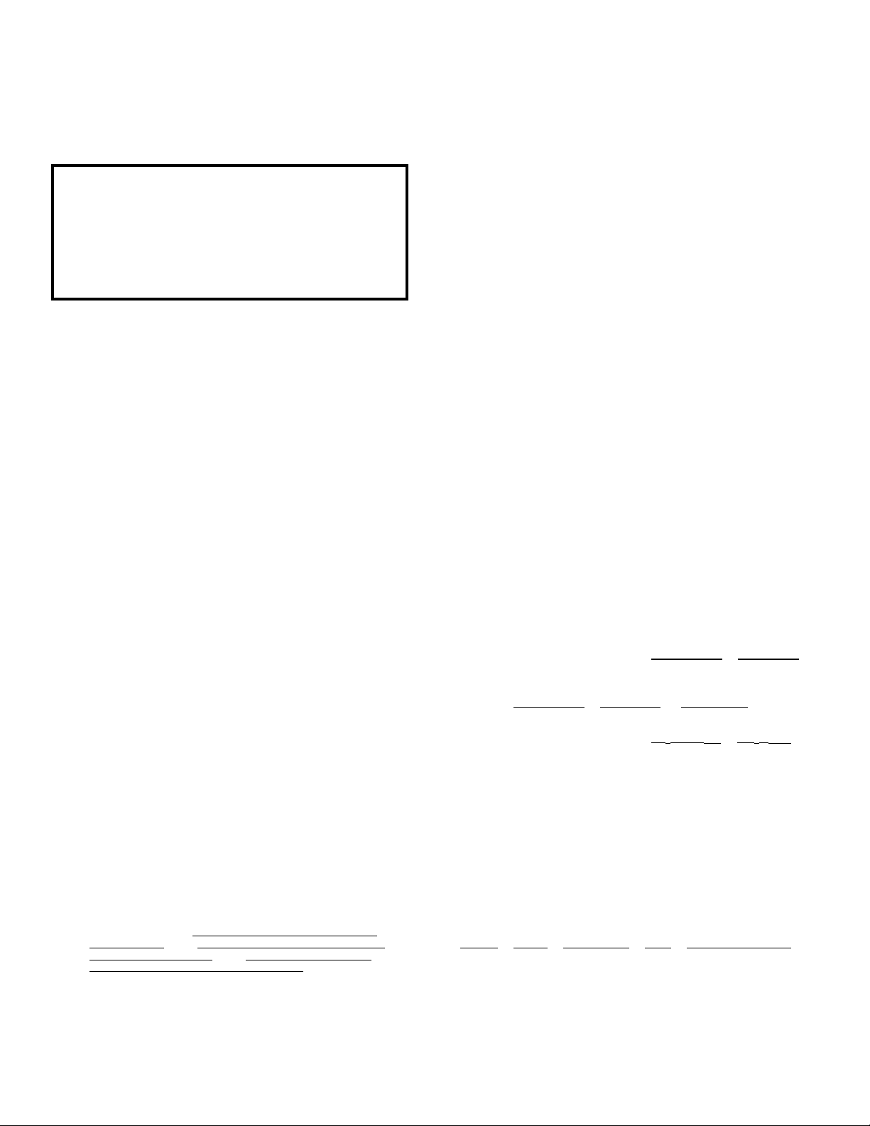
Minimum clearances from combustible materials
without protection:
Model R77 ( See figure 1)
Sides Back Fuel Door Top Connector Pipe
A B
36" 36" 36" 36" 18"
2. IF APPROVED FLOOR PROTECTION IS NOT
USED: Use the following calculation to
5. Minimum clearances from combustible materials
with protection:
2
The distances between the sides and/or back can be
reduced by placing an approved wall protection
panel over the combustible walls.
Consult NFPA 211 for reduced clearances allowed a
proper installation.
Figure 1
way, any possible creosote formation will drain
dow n the inside pipe.
(The R77-E comes equipped with a cast iron
damper in the flue collar. You may need to cut
slots in your stove pipe to fit over the dam per rod.)
IMPORTANT: ALL PIPE JOINTS AND THE
CONNECTION TO THE HEATER COLLAR SHOULD
BE SECURED WITH AT LEAST THREE METAL
SCREWS.
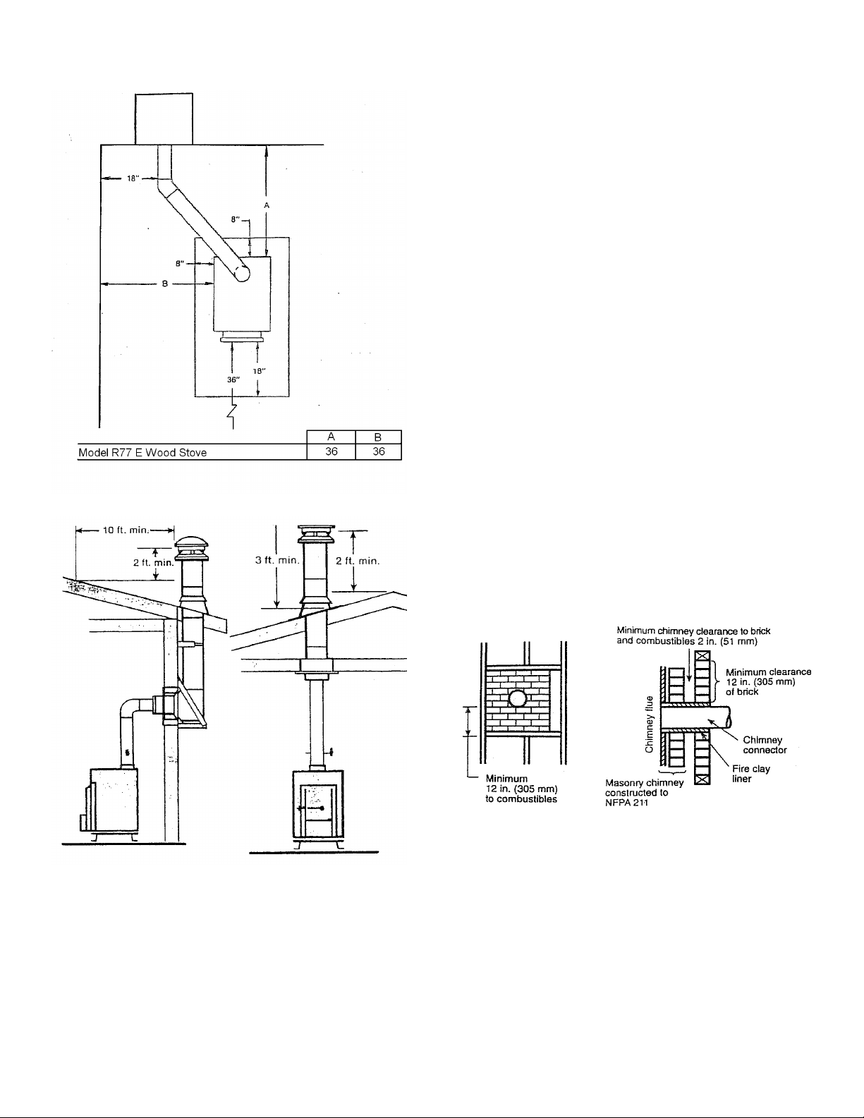
The connector pipe should be at least 18 inches or
more from combustible materials.
The connector pipe should be as straight and
short as possible (keeping minimum clearances in
mind). It should have no more than two 90 degree
elbows.
The horizontal connectors are required by NFPA
(National Fire Protection Association) No.211 to
have at least ¼ inch rise to the linear foot. It
should be easily accessible for cleaning, and
should not pass through walls, floors or ceiling
without being properly insulated for heat.
The connector pipe should not be installed outside
or through unheated inside areas because
condensation of hot gasses coming in contact
with a cold pipe will cause rapid creosote
accumulations.
THIS ROOM HEATER MUST BE CONNECTED TO:
(1) A Listed Type HT (2100F) chimney per UL 103
or ULC S629
(2) A code-approved masonry chimney with a flue
liner. The chimney size should not be less than
or more than three times greater than the cross
sectional area of the flue collar.
Figure 2 Figure 3
D. Connector Pipe Installation
This connector pipe connects the heater to the
chim ney.
On Shenandoah heaters, this pipe should be at
least 6 inches in diameter, 24 gauge, or heavier,
black pipe.
It is recommended that connector pipes be
installed with the crimped end down, including the
section which goes into the heater collar. In this
CHIMNEY CONNECTOR SYSTEMS AND
CLEARANCES FROM COMBUSTIBLE WALLS FOR
RESIDENTIAL HEATING APPLIANCES
A. Minimum 3.5 inch thick brick masonry all framed
into combustible wall with a minimum of 12 inch
brick separation from clay liner to combustibles.
The fireclay liner shall run from outer surface of
brick to wall, but not beyond the inner surface of the
chim ney flue liner and shall be firmly cemented in
place.
3
 Loading...