

Page 1
CoverTitle
PinPoint X
Quick Start Guide
for AT&T
20070914
Rev 3.0C
Page 2

Activating your PinPoint X on AT&T
• Installing the SIM
• Configuring the
APN
• Hardware
Installation
• Indicator Lights
• Optional: Setting up
a DUN
Connection
This Quick Start guide provides step-by-step directions for activating
your PinPoint X on AT&T’s network.
Tip:
For additional configuration options, refer to the User Guide for your
PinPoint X.
H
Installing the SIM
The Subscriber Identity Module (SIM) in the PinPoint X is a
smartcard that securely stores the key identifying a cellular
subscriber. Generally, you will only need to install a SIM once in the
life of the modem and it may be pre-installed by your Sierra Wireless
Representative.
If the SIM was pre-installed, unless you need to set a custom APN,
activation of your modem is complete. Skip to the PinPoint X
Placement section and/or to the DUN instructions, if you need DialUp Networking.
Cellular Account Required
• Cellular Account Required- To use your modem, you need to
have a SIM with an active account with your cellular provider.
Software Required
• ACEmanager - Graphical interface for entering most AT
Commands. You can download ACEmanager from the Sierra
Wireless AirLink Solutions website: http://
www.sierrawireless.com/support/. A default installation of this
utility is assumed later in these directions
Hardware Required
• Ethernet cable or serial cable - An Ethernet cable or straight
through serial cable.
Rev 3.0C Mar.10 23
Page 3
PinPoint X HSUPA/HSDPA
• Serial cable - A straight through serial cable.
Note: Until you install a driver for the USB port, you cannot use your USB port to configure
the modem.
• Power adapter and a power source - You will need a power supply and
power source for the modem.
• PC or laptop - To configure the modem, you will need a computer with an
available Ethernet port or serial port.
Tools Required
• Small Phillips screw driver - The Phillips screw driver is the one which is
also called a plus (+) or X screw driver.
• Slim stylus - A PDA stylus, an unbent paperclip, or other such item.
Procedure
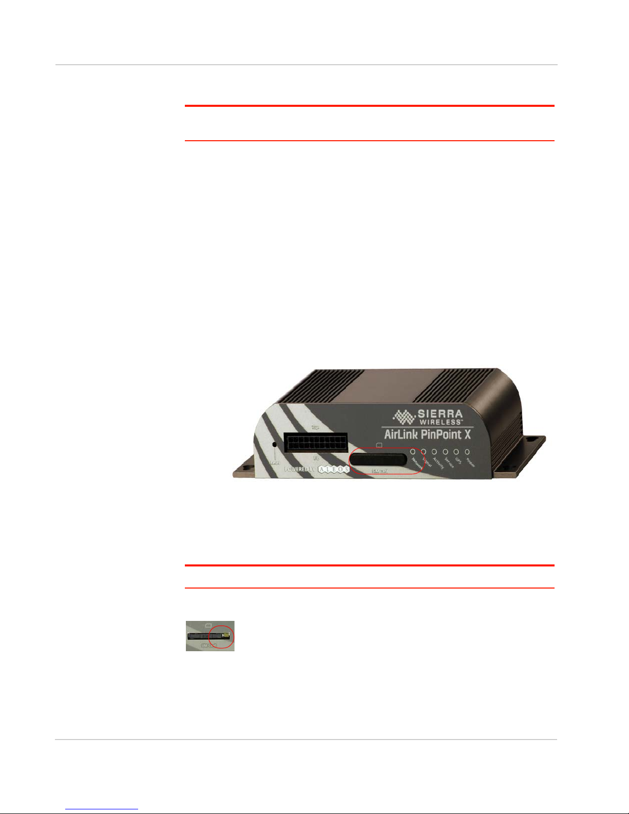
a. Unplug the PinPoint X power and all cables.
b. Remove slot cover on the front of the PinPoint X to reveal the SIM slot.
Figure 0-1: Slot Cover
c. Carefully remove the SIM card from the card you received from AT&T.
d. Using the tip of a PDA stylus, an unbent paperclip, or other slim blunt item
press the yellow button of the SIM tray.
Tip:
The button is between two boards.
e. Slide the tray out completely.
Figure 0-2: SIM tray button
24 20070914
Page 4
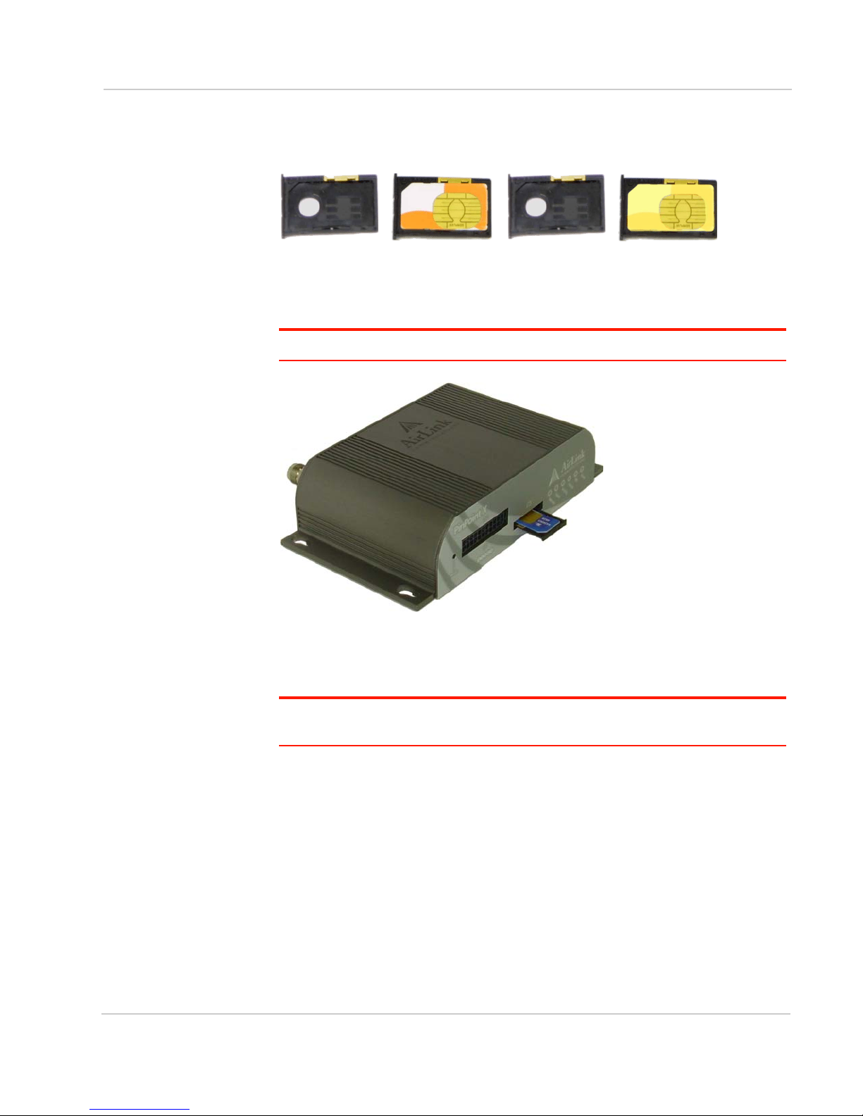
f. Place the SIM into the tray and gently press to click it into place.
Figure 0-3: Empty SIM Tray and a Tray with a Sample SIM
g. Slide the tray back into the modem.
h. Gently press the SIM to click it into place.
Tip:
The top of the card faces the bottom of the modem.
Figure 0-4: Inserting the SIM
Replace the cover to prevent dust or other unwanted particles from entering the
PinPoint X. Once the cover is replaced, the installation is complete.
Note: The first time you power on your PinPoint X with your new SIM, there may be a
delay of up to 10 minutes for the initial network connection to occur.
Rev 3.0C Mar.10 25
Page 5

PinPoint X HSUPA/HSDPA
Configuring the APN
The APN (Access Point Name) is the way your device knows how it will be
communicating with the network. The APN allows custom IP addressing and
tailoring your company's wireless IP solution to meet the security and IP
addressing requirements of your applications.
Note: Most accounts use the default addressing solution of Private or Public IP addresses
supplied by the Internet and Proxy APNs. Only if you have a Static or Custom IP address
should you need to configure a custom APNs.
The default APN is Internet. If you need a different APN, use ACEmanager to
configure it.
Hardware Installation
Note: During installation,
please be sure that the
cables are secure but do
not bear any additional
weight that could loosen
the connector from the
unit.
Your PinPoint X should be mounted in a position that allows easy access for the
cables so they are not bent, constricted, in close proximity to high amperage, or
exposed to extreme temperatures. The LEDs on the front panel should be visible
for ease of operational verification. You should ensure that there is adequate
airflow around the modem but that it is kept free from direct exposure to the
elements, such as sun, rain, dust, etc.
Caution:
extreme environments. However, unless you are using cables expressly designed for such
environments, they can fail if exposed to the same conditions the PinPoint X can
withstand.
The PinPoint X is in a hardened case and designed for use in industrial and
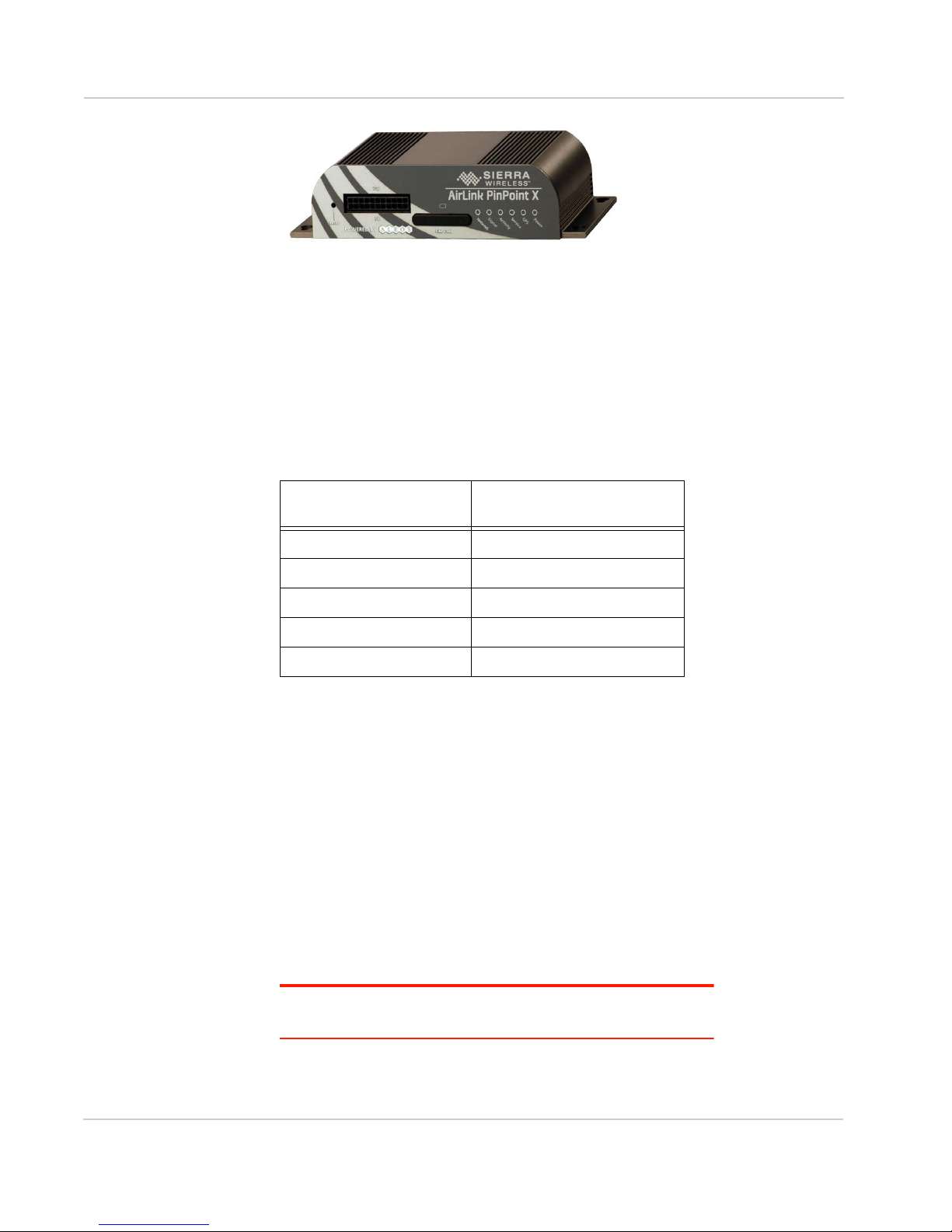
Figure 0-5: PinPoint X Connectors
26 20070914
Page 6
Cellular
Note: This device is not
intended for use within
close proximity of the
human body. Antenna
installation should provide
for at least a 20 CM
separation from the
operator.
Antennas selected should not exceed a maximum gain of 5 dBi under standard
installation configuration. In more complex installations (such as those requiring
long lengths of cable and/or multiple connections), it’s imperative that the installer
follow maximum dBi gain guidelines in accordance with the radio communications
regulations of the Federal Communications Commission (FCC), Industry Canada,
or your country’s regulatory body (if used outside the US).
Your PinPoint X will work with most cellular antennas with a connector. Connect
the primary antenna or primary RF cable directly to the antenna connector on the
back of the PinPoint X.
Tip:
When using a cable to an antenna placed away from the modem, minimize the length
of your cable. All gain from a more advantageous antenna placement can be lost with a
long cable to the modem.
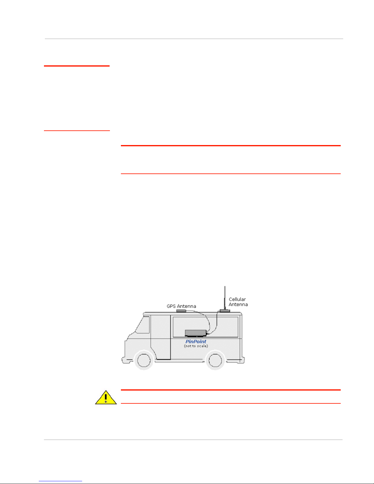
Your PinPoint X will work with most standard active GPS antennas. Connect the
GPS antenna or cable directly to the threaded SMA connector.
Mount the GPS Antenna in the vehicle. The less the cable is wrapped and bound
together, the better it will perform. Place it on the roof, or on the dash, or rear
panel where it has a good view of the sky (greater than a 90 angle view of the
sky).
There are three options for antenna mounts:
• Magnetic roof-mount
• Through glass-mount
• Permanent mount
Figure 0-6: GPS Antenna Placement for a Vehicle
Warning:
Rev 3.0C Mar.10 27
Risk of electric shock: Only use the supply voltages listed in this user guide.
Page 7
PinPoint X HSUPA/HSDPA
Ignition Sense (white)
Power (red)Ground (black)
Not Used
Warning:
40 0C.
Your PinPoint X can be used with either DC or AC, with the appropriate power
adapter. DC cables and AC adapters are available as optional accessories in
addition to the one included with your PinPoint X.
The DC power cable positive lead should be connected to the battery or power
source positive terminal. The power cable negative lead should be connected to
the battery or power source negative terminal.
The battery cable used for a car, truck, or other mobile connection must be less
than 3 meters in length.
The PinPoint X has an internal polysilicon circuit breaker that opens at 0.5 to 1.0
amps of current.
If you wish to use the Standby Ignition Sense (SISE) feature of your PinPoint X,
the white wire of the three wire DC power cable should be used to connect to your
ignition. When SISE is enabled in the modem and the ignition sense connector is
wired to your vehicle, the ignition sense will provide a link to the modem to enable
it to enter a low-power, standby mode when your vehicle is turned off and power
up more quickly when the ignition is started.
Figure 0-7: Ignition Sense power connector
When using AC to DC adapter the ambient temperature should not exceed
Warning:
switched off or the area is known to be non-hazardous.
Explosion Hazard - Do not disconnect equipment unless power has been
Connecting to a Computer or other
Device
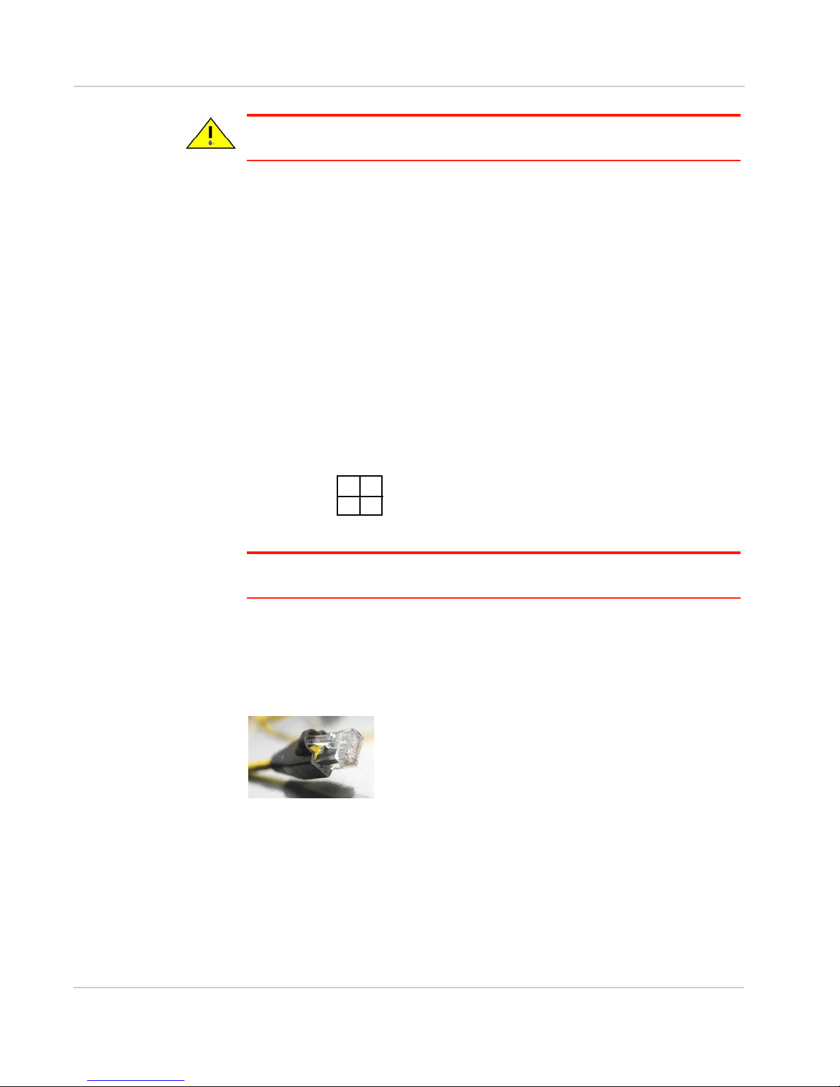
Figure 0-8: Ethernet
The Ethernet port of your PinPoint X can be connected directly to a computer or
other Ethernet device with either a cross-over cable or a straight-through cable.
The Ethernet port on the PinPoint X is auto-sensing and will auto-detect the
speed of the connecting device for 100baseTX or 10baseT. If you are connecting
the modem to a hub or switch you should use a straight through cable or use the
uplink port on the hub or switch with a cross-over cable.
28 20070914
Page 8
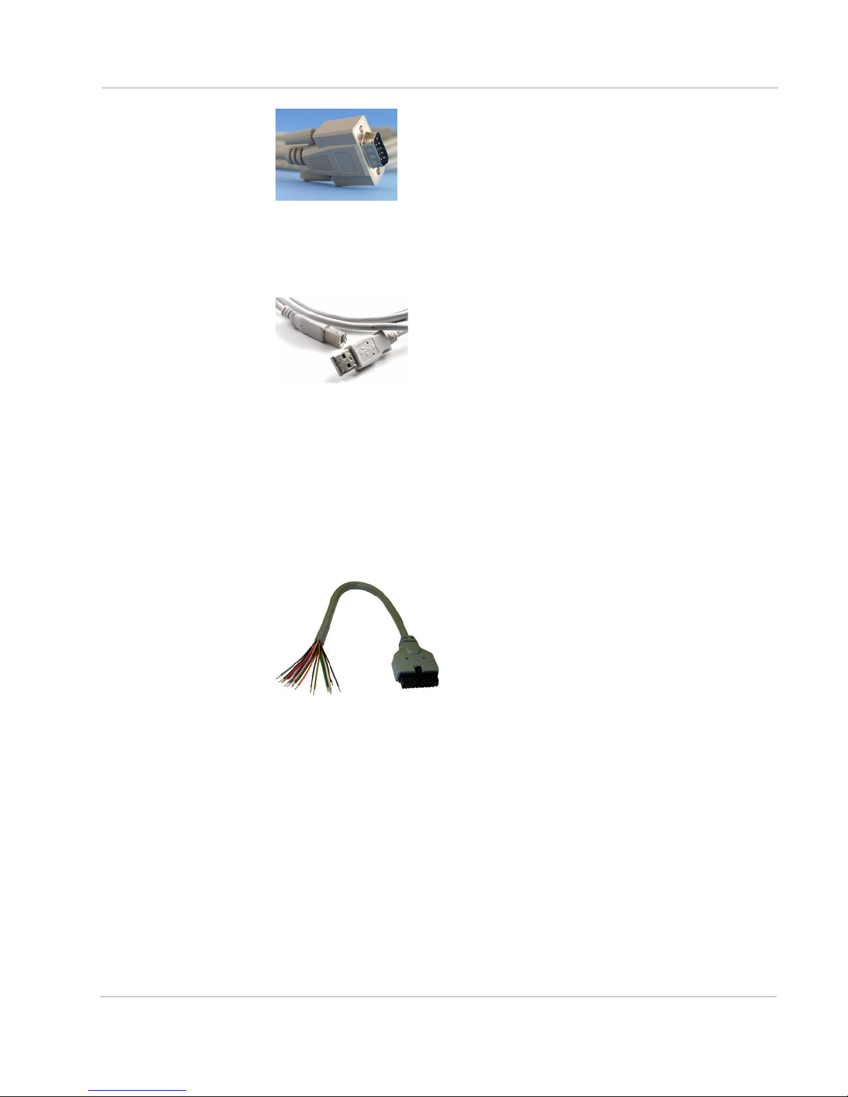
Figure 0-9: Serial
The serial port of your PinPoint X can be connected directly to most computers or
other devices using a standard straight through cable. If you have a DCE device,
you will need a null modem or null modem cable.
Figure 0-10: USB
Your PinPoint X’s full-speed (12 Mbit) USB 2.0 port can be connected directly to
most computers or other devices using a standard full-speed USB 2.0 cable. If the
computer or device you are connecting or the cable is not rated for full-speed, the
modem will communicate at a reduced speed to match. The PinPoint X functions
as a device, not a host.
When it is connected to a computer, the USB port should be seen as a COM port
or Ethernet port after the applicable driver is installed.
The PinPoint X has a standard B connector.
Figure 0-11: I/O
Your PinPoint X also has an I/O port with digital inputs, analog inputs, and relay
outputs which can be connected to external devices.
The I/O port can use an optional I/O harness available through Sierra Wireless.
Indicator Lights
When solid, PinPoint X indicates a successful connection. When your PinPoint X
is connected to power and an antenna, there is a specific pattern to the lights to
indicate its operation mode.
Rev 3.0C Mar.10 29
Page 9
PinPoint X HSUPA/HSDPA
Figure 0-12: PinPoint X Indicator lights
•Network - Indicates a successful connection to the cellular network with an
IP address given and a channel acquired.
• Signal - Light shows the strength of the signal and may be nearly solid
(strong signal) or flashing (weaker signal). A slow flash indicates a very weak
signal.
RSSI LED Ranges
RSSI/Signal LED
Status
On Solid Equal to or stronger than -69
Fast Blink -70 to -79
Normal blink -80 to -89
Slow Blink -90 to -99
Extinguished Equal to or weaker than -100
Ranges of RSSI (dBm)
•Activity - Lights will flash as data is transferred to and from the PinPoint
modem on the remote network.
• Service - Indicates when the connection is HSUPA/HSDPA or UMTS. Unlit
indicates EDGE or GPRS.
•GPS - Indicates a GPS fix. When lit, the PinPoint X has GPS coordinates to
report.
•Power - Indicates the power adapter is connected and there is power getting
to the PinPoint X.
• The Reset button (on the left side of the PinPoint X) has two functions. If it is
quickly depressed and released, the modem will simply power cycle the
internal hardware. If, however, the reset is depressed and held for several
seconds (count 10 slowly, and wait for the power light to go off after the light
pattern stops), the ALEOS configuration settings will return to the factory
defaults.
Caution:
you may to reconfigure your APN.
30 20070914
If you reset the modem configuration using the reset button,
Page 10

Light Patterns
The LEDs on the front of the modem will respond in different patterns to indicate
modem states.
• Normal - Each LED, mentioned above, is lit as applicable.
•Start up - The LEDs will cycle from left to right.
• PassThru mode - Network and Signal LEDs will blink in tandem. The
Activity LED will blink when transmitting or receiving data.
•SOS - The Network Channel and Service Err or Service LEDs will blink
alternate to each other.
•Low Power - All LEDs will be off except the power LED which will blink every
3 seconds.
• Configuration Reset - The LEDs will cycle left to right and then right to left 4
times.
• Authentication Failure - The Network, Signal, and Activity LEDs blink every
2 seconds.
• Data Retry - The Network, Signal, and Activity LEDs blink every 3 seconds.
• Invalid MAC Address or Ethernet Initiation Fail - The Service LED will
blink.
Optional: Setting up a DUN Connection
Dial-up Networking (DUN) allows a computer or other device to use the serial port
or ethernet port on your PinPoint X to connect to the Internet or private network
using PPP just like an analog modem using a standard phone line.
Caution:
istrator or have Administrator privileges for your login.
Microsoft Windows XP is used in the examples below. The modem driver
installation and DUN setup and configuration is similar in Microsoft Windows
products. Examples are not provided here for installing the driver or configuring
DUN for any other operating system.
\
Standard installations of Microsoft Windows XP and 2000 include a generic
device driver which will work with your PinPoint X.
1. Connect the PinPoint X.
2. Install the driver.
To install any driver on your computer, you may need to be logged in as Admin-
a. Connect the device to the computer with a DB-9 cable or the USB port in
serial mode.
b. Plug in the AC adapter, connect the antenna(s) and power on the device.
a. Select Start > Control Panel > Phone and device Options (in Classic
View).
Rev 3.0C Mar.10 31
Page 11

PinPoint X HSUPA/HSDPA
Figure 0-13: Phone and device Options
b. Select the devices tab.
Figure 0-14: Phone and device Options: devices
c. Select Add.
32 20070914
Page 12

Figure 0-15: Add Hardware Wizard
d. Check Don’t detect my device; I will select it from a list.
e. Select Next.
Figure 0-16: Add Hardware Wizard: Install New device
Tip:
use the Standard device that matches the speed you configured.
Rev 3.0C Mar.10 33
f. Select (Standard device Types) from the Manufacturers column.
g. Select Standard 33600 bps device from the Models column.
If you have the speed for your device configured as something other than the default,
h. Select Next.
Page 13

PinPoint X HSUPA/HSDPA
Figure 0-17: Add Hardware Wizard: Select Ports
i. Check Selected Ports.
j. Select the COM port the device is connected to (commonly COM1).
k. Select Next.
Figure 0-18: Add Hardware Wizard: Finish
l. Once the device driver is installed, select Finish.
When you return to the Phone and device Options window, you should see the
newly installed device “attached to” the correct COM port.
34 20070914
Page 14

Figure 0-19: Phone and device Options: devices
a. Highlight the device and select Properties.
Figure 0-20: device Properties
Rev 3.0C Mar.10 35
b. Select the device tab.
Page 15

PinPoint X HSUPA/HSDPA
Figure 0-21: device Properties: device
c. Maximum Port Speed should be set to 115200 (default).
d. Select OK to exit.
e. Select OK again to exit out of the Phone and device Options.
Creating a Dial-Up Networking (PPP)
Connection
Once you have the driver for the modem installed on your computer, you can set
up and configure Dial Up Networking (DUN) to use the modem as your
connection to the Internet using PPP.
Note: No other device or program can be using the same COM port (serial port)
configured for the modem driver.
Caution:
interfere with the LAN connection. It's recommended to disconnect your LAN connection
before using a PPP connection with your PinPoint X.
Once the DUN connection is initiated, by default, it will take over as the “default
route” for network communication and specifically for Internet access. If you want
the two connections to co-exist, you will need to de-select “Use default gateway
on remote network” (described later) and use the route command in Windows to
setup routing through the modem properly. This guide does not provide
information on the route command. You may need to consult with your network
administrator to properly configure routing.
1. Create a new network connection.
If you have an existing LAN connection, installing DUN for the modem may
36 20070914
Page 16

a. Select Start > Connect To > Show All Connections to open the Network
Connections window.
Figure 0-22: Windows : Start menu
b. Select Create a New Connection under Network Tasks in the menu area
on the left.
Figure 0-23: Create New Connection
c. Select Next to start installing and configuring the DUN connection.
Rev 3.0C Mar.10 37
Page 17

PinPoint X HSUPA/HSDPA
Figure 0-24: New Connection Wizard
d. Select Connect to the Internet.
e. Select Next.
Figure 0-25: New Connection: Type
f. Select Set up my connection manually.
g. Select Next.
Figure 0-26: New Connection: How do you want to connect?
h. Select Connect using a dial-up modem.
i. Select Next.
38 20070914
Page 18

Figure 0-27: New Connection: Connect using...
j. Optional: If you have multiple modems installed on your computer, you
may be prompted to select the modem to be used. If you only have one
modem installed, this option will be omitted.
k. Check Standard 33600 bps Modem.
l. Select Next.
Figure 0-28: New Connection: Select Modem
m. Type in a name for the connection, such as Sierra Wireless AirLink
Modem.
n. Select Next.
Figure 0-29: New Connection: Connection Name
Tip:
the icon. It can be the name of your wireless service provider (Provider), your modem
(PinPoint X), or any other designation for the connection.
Rev 3.0C Mar.10 39
The name provided here will not effect the connection in any way. It is only a label for
o. Typ e i n 10001 as the phone number for the modem to dial.
p. Select Next.
Page 19

PinPoint X HSUPA/HSDPA
Figure 0-30: New Connection: Phone Number
q. Optional: If you have multiple users configured for your computer, you
may be prompted for Connection Availability. If you select My use only,
the account currently logged on will be the only one able to use this DUN
connection.
r. Select Next.
Figure 0-31: New Connection: Permissions
Generally the modem takes care of the Account Information, User name and
Password, for the connection, so you can leave the fields blank (unless otherwise
instructed by Support).
s. If you want to allow others to use the same login for the modem, select
Use this account name and password....
t. Select Next.
Figure 0-32: New Connection: Connection Information
Caution:
Internet Connection for the DUN configuration, you will not be able to use the LAN to
connect to the Internet and may also affect the network connection on your computer to
the rest of the LAN. Select this option ONLY if the PinPoint X will be your sole network
connection.
If you have a LAN connection to the Internet and select Make this the default
40 20070914
Page 20

u. If you want to add a shortcut for this DUN connection to your desktop,
check Add a shortcut.
v. Select Finish to exit the Network Connection Wizard.
Figure 0-33: New Connection: Finish
2. Configure the DUN connection
After you complete the New Connection Wizard, there are a few more things you
will want to configure in the connection.
a. Select Properties.
Figure 0-34: DUN Connection
Rev 3.0C Mar.10 41
Page 21

PinPoint X HSUPA/HSDPA
b. Uncheck Use dialing rules.
c. Check Show icon...when connected.
d. Select Configure, below the Connect using line.
Figure 0-35: DUN Properties
e. Select 115200 as the Maximum speed.
f. Check Enable hardware flow control.
g. Do not check any other option.
h. Select OK.
Figure 0-36: Modem Configuration
42 20070914
Page 22

i. Back at the main properties screen, select the Networking tab.
Figure 0-37: Networking
j. Select Settings.
k. Remove the checks from all three PPP settings.
l. Select OK.
Figure 0-38: PPP Settings
m. Select (highlight) Internet Protocol (TCP/IP) and then select Properties.
Tip:
For most configurations, you will be obtaining the IP address and the DNS server
address automatically.
n. Select Advanced.
Rev 3.0C Mar.10 43
Page 23

PinPoint X HSUPA/HSDPA
Figure 0-39: TCP/IP Properties
o. Uncheck Use IP header compression.
p. Check Use default gateway on remote network.
q. Select OK.
Figure 0-40: Advanced TCP/IP
Tip:
You may want to check the Options tab and change the settings for applications you
might be using. The default options are generally applicable for most uses.
Caution:
Unless specifically directed to do so by Support or your network administrator,
you do not need to make any changes to the options on the Security tab.
r. Select OK until you return to the Connect window.
44 20070914
Page 24

Connecting to the Internet Using DUN
There are two methods you can use to connect with PinPoint X to the Internet
using DUN, AceView and the Windows DUN connection directly.
ACEview
ACEview is a small utility which can maintain your DUN connection and monitor
the connection of your PinPoint X to Provider. If you have not already installed
ACEview you can obtain the most recent version from the Sierra Wireless AirLink
website.
Note: The direct DUN
connection features of
ACEview are not available
in Windows 98 or Windows
NT.
This guide assumes you have a default installation of ACEview.
1. Start ACEview.
Start > All Programs > AirLink Communications > ACEview
Figure 0-41: ACEview: Menu
a. Right-click on the ACEview window to open the menu.
b. Select Connection Settings.
Figure 0-42: ACEview: Connection Settings
When checked, ACEview will continually check the DUN connection to ensure it is
not down. If so, ACEview will attempt to connect again.
Rev 3.0C Mar.10 45
c. Select Auto Start in the DUN section.
d. Select Maintain Persistent Connection.
Page 25

PinPoint X HSUPA/HSDPA
Tip:
When using the DUN connection, make sure the IP Address is set to the local IP
address of the modem, 192.168.13.31 by default.
e. Select OK.
f. OK.
Windows DUN
You can directly use the Dial-up link for the DUN connection.
1. Start the DUN session.
Start > Connect To > Sierra Wireless AirLink Modem
If you named the connection differently, use the name of the PPP connection you
made earlier.
Figure 0-43: DUN Connection
Tip:
Generally you will not need to enter a Username or Password. If you do need to enter
either, you can enter these parameters beforehand using *NETUID and *NETPW.
2. Select Dial to connect to the modem and the cellular network.
46 20070914
Page 26

Note: The speed shown in
the connection is the
speed between the
modem and your
computer, it is not the
speed of the modem’s
connection to Provider or
the Internet.
When you’re connected, an icon should appear in the system tray showing the
connection status.
Figure 0-44: Connection indicator
Caution:
For DUN connections on a Windows Mobility or other non-personal computer,
the DNS settings may not be configured with the DUN connection. You may need to go into
the network settings and add DNS servers manually.
Rev 3.0C Mar.10 47
Page 27

 Loading...