

Page 1

PC3320 Wireless Network
Card
Installation Guide
2130361
Rev 1.0
Page 2

Page 3

Preface
Important Notice
Due to the nature of wireless communications, transmission and reception of data
can never be guaranteed. Data may be delayed, corrupted (i.e., have errors) or
be totally lost. Although significant delays or losses of data are rare when wireless
devices such as the modem are used in a normal manner with a well-constructed
network, the modem should not be used in situations where failure to transmit or
receive data could result in damage of any kind to the user or any other party,
including but not limited to personal injury, death, or loss of property. Verizon
accepts no responsibility for damages of any kind resulting from delays or errors
in data transmitted or received using the modem, or for failure of the modem to
transmit or receive such data.
Safety and Hazards
Do not operate the modem in areas where blasting is in progress, where
explosive atmospheres may be present, near medical equipment, near life
support equipment, or any equipment which may be susceptible to any form of
radio interference. In such areas, the modem MUST BE POWERED OFF. The
modem can transmit signals that could interfere with this equipment.
Do not operate the modem in any aircraft, whether the aircraft is on the ground or
in flight. In aircraft, the modem MUST BE POWERED OFF. When operating, the
modem can transmit signals that could interfere with various onboard systems.
Note: Some airlines may permit the use of cellular phones while the aircraft is on
the ground and the door is open. The modem may be used at this time.
The driver or operator of any vehicle should not operate the modem while in
control of a vehicle. Doing so will detract from the driver or operator's control and
operation of that vehicle. In some states and provinces, operating such communications devices while in control of a vehicle is an offence.
Limitation of Liability
The information in this manual is subject to change without notice and does not
represent a commitment on the part of Verizon. VERIZON AND ITS AFFILIATES
SPECIFICALLY DISCLAIM LIABILITY FOR ANY AND ALL DIRECT, INDIRECT,
SPECIAL, GENERAL, INCIDENTAL, CONSEQUENTIAL, PUNITIVE OR
EXEMPLARY DAMAGES INCLUDING, BUT NOT LIMITED TO, LOSS OF
PROFITS OR REVENUE OR ANTICIPATED PROFITS OR REVENUE ARISING
OUT OF THE USE OR INABILITY TO USE ANY VERIZON PRODUCT, EVEN IF
VERIZON AND/OR ITS AFFILIATES HAS BEEN ADVISED OF THE POSSIBILITY OF SUCH DAMAGES OR THEY ARE FORESEEABLE OR FOR CLAIMS
BY ANY THIRD PARTY.
Rev 1.0 Mar.04 1
Page 4

Installation Guide
Notwithstanding the foregoing, in no event shall Verizon and/or its affiliates
aggregate liability arising under or in connection with the product, regardless of
the number of events, occurrences, or claims giving rise to liability, be in excess
of the price paid by the purchaser for the product.
Patents
Portions of this product are covered by some or all of the following US patents:
5,515,013 5,617,106 5,629,960 5,682,602 5,748,449 5,845,216 5,847,553
5,878,234 5,890,057 5,929,815 6,169,884 6,191,741 6,199,168 6,327,154
6,339,405 6,359,591 6,400,336 6,643,501 6,516,204 6,561,851 6,653,979
D367,062 D372,248 D372,701 D416,857 D442,170 D452,495 D452,496
D453,733 D459,303
and other patents pending.
This product includes
technology licensed from
QUALCOMM Incorporated under one or more of the following United States patents and/or
their counterparts in other nations:
4901307 5056109 5101501 5109390 5228054 5267261 5267262 5337338
5414796 5416797 5490165 5504773 5506865 5511073 5535239 5544196
5568483 5600754 5657420 5659569 5710784 5778338
Copyright
©2004 Sierra Wireless. All rights reserved.
2 2130361
Page 5

Trademarks
Windows® is a registered trademark of Microsoft Corporation.
Qualcomm
InstallShield
ration.
Other trademarks are the property of the respective owners.
®
is a registered trademark of Qualcomm Incorporated.
®
is a registered trademark and service mark of InstallShield Corpo-
Preface
Rev 1.0 Mar.04 3
Page 6

Installation Guide
4 2130361
Page 7

Table of Contents
Introducing the PC3320 Wireless Network Card . . . . . . . . . . . . . . .7
Welcome . . . . . . . . . . . . . . . . . . . . . . . . . . . . . . . . . . . . . . . . . . . . . . . . . . . . 7
Feature summary . . . . . . . . . . . . . . . . . . . . . . . . . . . . . . . . . . . . . . . . . . . . . . 7
Network card . . . . . . . . . . . . . . . . . . . . . . . . . . . . . . . . . . . . . . . . . . . . . . .7
Modem . . . . . . . . . . . . . . . . . . . . . . . . . . . . . . . . . . . . . . . . . . . . . . . . . . . . 8
Other . . . . . . . . . . . . . . . . . . . . . . . . . . . . . . . . . . . . . . . . . . . . . . . . . . . . .8
CDMA 1X services . . . . . . . . . . . . . . . . . . . . . . . . . . . . . . . . . . . . . . . . . . .8
Additional PC3320 features . . . . . . . . . . . . . . . . . . . . . . . . . . . . . . . . . . . .9
Package contents. . . . . . . . . . . . . . . . . . . . . . . . . . . . . . . . . . . . . . . . . . . . . . 9
System components. . . . . . . . . . . . . . . . . . . . . . . . . . . . . . . . . . . . . . . . . . . . 9
Your host computing device . . . . . . . . . . . . . . . . . . . . . . . . . . . . . . . . . . . .9
The PC3320 wireless network card . . . . . . . . . . . . . . . . . . . . . . . . . . . . . .9
The PC3320 card drivers and enabling software . . . . . . . . . . . . . . . . . . .10
A CDMA service provider account . . . . . . . . . . . . . . . . . . . . . . . . . . . . . .10
The CDMA wireless network . . . . . . . . . . . . . . . . . . . . . . . . . . . . . . . . . .11
Care and Maintenance of Your PC3320 card . . . . . . . . . . . . . . . . .13
Getting Started . . . . . . . . . . . . . . . . . . . . . . . . . . . . . . . . . . . . . . . 15
The PC3320 software. . . . . . . . . . . . . . . . . . . . . . . . . . . . . . . . . . . . . . . . . . 15
Account activation and configuration . . . . . . . . . . . . . . . . . . . . . . . . . . . . . . 15
Installation . . . . . . . . . . . . . . . . . . . . . . . . . . . . . . . . . . . . . . . . . . . 17
System requirements . . . . . . . . . . . . . . . . . . . . . . . . . . . . . . . . . . . . . . . . . . 17
PC3320 card software installation procedures. . . . . . . . . . . . . . . . . . . . . . . 18
Venturi™ Software Installation . . . . . . . . . . . . . . . . . . . . . . . . . . . . . . . . .19
Card insertion and removal . . . . . . . . . . . . . . . . . . . . . . . . . . . . . . . . . . . . . 20
Inserting the PC3320 card . . . . . . . . . . . . . . . . . . . . . . . . . . . . . . . . . . . . 20
Removing the PC3320 card . . . . . . . . . . . . . . . . . . . . . . . . . . . . . . . . . . .20
Rev 1.0 Mar.04 5
Page 8

Installation Guide
Activation . . . . . . . . . . . . . . . . . . . . . . . . . . . . . . . . . . . . . . . . . . . 21
Account configuration procedures . . . . . . . . . . . . . . . . . . . . . . . . . . . . . . . . 21
Activation Wizard . . . . . . . . . . . . . . . . . . . . . . . . . . . . . . . . . . . . . . . . . . . 21
Manual activation. . . . . . . . . . . . . . . . . . . . . . . . . . . . . . . . . . . . . . . . . . . . . 22
Automated activation . . . . . . . . . . . . . . . . . . . . . . . . . . . . . . . . . . . . . . . . . . 22
Mobile Connection Manager™ Basics . . . . . . . . . . . . . . . . . . . . . . 23
Starting and closing Mobile Connection Manager . . . . . . . . . . . . . . . . . . . . 23
Components of the Mobile Connection Manager window . . . . . . . . . . . . . . 24
Window controls . . . . . . . . . . . . . . . . . . . . . . . . . . . . . . . . . . . . . . . . . . . 24
Docking . . . . . . . . . . . . . . . . . . . . . . . . . . . . . . . . . . . . . . . . . . . . . . . . . . 25
Always On Top . . . . . . . . . . . . . . . . . . . . . . . . . . . . . . . . . . . . . . . . . . . . 25
Interpreting icons . . . . . . . . . . . . . . . . . . . . . . . . . . . . . . . . . . . . . . . . . . . . . 25
Connection Status Area . . . . . . . . . . . . . . . . . . . . . . . . . . . . . . . . . . . . . 26
Call Status Area . . . . . . . . . . . . . . . . . . . . . . . . . . . . . . . . . . . . . . . . . . . 27
Indicator area . . . . . . . . . . . . . . . . . . . . . . . . . . . . . . . . . . . . . . . . . . . . . 27
Minimized Icons . . . . . . . . . . . . . . . . . . . . . . . . . . . . . . . . . . . . . . . . . . . . 28
Online Help . . . . . . . . . . . . . . . . . . . . . . . . . . . . . . . . . . . . . . . . . . . . . . . . . 28
Troubleshooting. . . . . . . . . . . . . . . . . . . . . . . . . . . . . . . . . . . . . . . . . . . . . . 29
Technical Specifications . . . . . . . . . . . . . . . . . . . . . . . . . . . . . . . 31
LED operation . . . . . . . . . . . . . . . . . . . . . . . . . . . . . . . . . . . . . . . . . . . . . . . 31
Radio frequency and electrical specifications . . . . . . . . . . . . . . . . . . . . . . . 32
Environmental specifications . . . . . . . . . . . . . . . . . . . . . . . . . . . . . . . . . . . . 32
Glossary . . . . . . . . . . . . . . . . . . . . . . . . . . . . . . . . . . . . . . . . . . . . 33
6 2130361
Page 9

Wireless Network Card
•Welcome
• Feature Summary
• Package Contents
• System Components
Welcome
Note: Do not insert the PC3320 card into your PC Card slot prior to installing the
software. It is important to install the software and driver in the correct order. For
detailed procedures, see page 17.
The PC3320 wireless network card is a dual-band wireless PC Card for cellular
and North American PCS networks. It enhances the functionality of your mobile
computing devices by adding wireless data and 2-way messaging.
The PC3320 functions as a wireless network card (with LAN-like connectivity),
and a modem. This card allows you to connect to the Internet, send and receive
e-mail, connect to a corporate network, without the need of a network cable or
phone line.
11: Introducing the PC3320
Feature summary
Note: For step-by-step instructions to access features of the PC3320, consult the
online help available with Mobile Connection Manager.
The PC3320 wireless network card is designed to provide a wide range of
capabilities using CDMA network technology. Implementation of these features
will depend on the particular service provider and account features you have
chosen.
Some features described in this manual may not be supported by your service
provider or may not be available with your network account. Contact your service
provider for details of the services and accounts available.
Network card
During high-speed packet connections, the PC3320 is a true network card,
functioning just like the network cards familiar to most corporate computer users.
Once installed and configured, the PC3320 card can connect to the CDMA
Rev 1.0 Mar.04 7
Page 10

Installation Guide
network automatically. You just insert the PC3320, start Mobile Connection
Manager and allow it to authenticate your account on the network, then launch
your Internet browser—you’re online!
Modem
As a modem, the PC3320 allows you to dial up any other modem (such as a
corporate server).
Other
Short Messaging Service (SMS) is available to exchange brief text messages with
other CDMA subscribers.
CDMA 1X services
The PC3320 operates over a type of wireless network called CDMA (Code
Division Multiple Access).
CDMA 1X technology provides a variety of connectivity features, depending on
your service provider and account:
• NationalAccess
supports Internet connections with data rates up to 153.6 kbps (downlink from
the network) and 76.8 kbps (uplink to the network). Actual speed will depend
on the network conditions. With this type of connection, the PC3320 card
functions as a network card.
Once the connection is established, you can open your browser and connect
to any web site that is accessible through the Internet, or access other Internet
services (such as e-mail).
SM
high-speed packet data, sometimes known as 1X,
Note: You may increase your data transmission speed by using compression
software. Contact your service provider for details.
• Circuit switched (dial-up) data, using the earlier CDMA IS-95 specification,
supports data connections to any dial-in service at rates up to 14.4 kbps.
Using Venturi data compression, the maximum data rate is 56 kbps.
• Quick 2 Net
SM
, provides a simplified way to dial into an Internet connection
(using circuit switched data).
• SMS (Short Message Service), allows you to send and receive short text
messages using the PC3320 card.
8 2130361
Page 11

Introducing the PC3320 Wireless Network Card
Additional PC3320 features
Beyond the features of the CDMA network, the PC3320 provides additional
software features:
• PIN security code to protect your PC3320 card and account from unautho-
rized use.
• An Activation Wizard (page 21) to assist with configuring your CDMA
accounts. The PC3320 supports two accounts.
• Sound options to customize ringtones for SMS messages.
• A Call Log to track outgoing calls and determine the amount of data trans-
ferred.
Package contents
Your PC3320 package contains the following components:
• PC3320 wireless network card
• Antenna
• Installation CD containing the PC3320 card software and this installation and
troubleshooting guide
• Quick Start Guide
• Warranty Card
System components
Your PC3320 wireless network card is just one part of a system designed to
provide you with a wide range of communication features. Every component of
the system is needed to enable these capabilities.
Your host computing device
Your notebook hosts the PC3320 card hardware and runs the communication
software: your web browser and e-mail application, and Mobile Connection
Manager—the PC3320 card enabling software.
You may also have other software on your computer that can be used wirelessly
with the PC3320, such as: file transfer applications (FTP), chat or instant
messaging, a VPN (Virtual Private Network) client, client software for a corporate
server application.
The PC3320 wireless network card
Along with the antenna, this equips your computer with a radio modem.
Rev 1.0 Mar.04 9
Page 12

Installation Guide
The PC3320 card fits into a standard Type II PC Card slot available on most
notebook PCs.
Every CDMA network operates on one of three radio frequency bands. As a dualband product, the PC3320 operates on two of these bands (see page 32),
providing a wide coverage area.
The PC3320 provides all the advantages of 1X where it is available while allowing
you to use the older CDMA IS-95 standard where 1X has not yet been implemented. The benefits to you are that you can use the PC3320 card in any area
that has coverage (assuming there are no account restrictions) and you will be
able to take advantage of the fastest possible data transmission speed.
The PC3320 card drivers and enabling software
Required to control, monitor, and manage your wireless connections, this includes
the Mobile Connection Manager application. The device drivers are the software
that enables the PC3320 card to work with your computer’s operating system.
The PC3320 card comes with a CD containing this software:
• Mobile Connection Manager application that you use to manage the PC3320
card and monitor your connections. Use the application’s online help for stepby-step instructions to access features of Mobile Connection Manager.
• Venturi compression software that increases data throughput, effectively
increasing the data transmission speed
• The device driver software that provides the interface between the PC3320
and your Windows
®
operating system.
The driver and application software must be installed before you insert the
PC3320 for the first time. Detailed instructions are provided in the following
chapter.
A CDMA service provider account
Companies that operate CDMA networks and provide access to these networks
are called service providers. You must have an account with a CDMA service
provider to use the PC3320.
Note: You can use the Lock Code feature to prevent others from using your
account should your PC3320 card be stolen. See the online help for information
on this feature.
Each service provider has its own pricing options. There may be flat rate
accounts, which provide you a maximum number of minutes of network usage for
a fixed monthly fee. There may be accounts for which you are charged for
network usage by the minute or by the amount of data transmitted.
Your account may include a variety of other services such as SMS messaging.
10 2130361
Page 13

Introducing the PC3320 Wireless Network Card
Each PC3320 has been provisioned at the factory for use with a particular service
provider. This sets the PC3320 card to use particular radio channels and enables
services specific for that provider.
The process of setting up your account is called activation. Activation involves
action by the service provider and configuration of the PC3320.
The procedure to configure (activate) your PC3320 card is covered in “Activation”
on page 21.
The CDMA wireless network
Note: More information about CDMA networks is available on the CDMA Development Group web site, www.cdg.org.
This is the worldwide infrastructure providing the radio coverage that allows you
to stay connected. Made up of radio towers, and a variety of network switches,
routers, and servers, the network is an interconnection of many service provider
companies.
Note: Most service providers have coverage maps on their web sites.
There are CDMA networks that operate in the frequency bands supported by the
PC3320 throughout North America and parts of Latin America, Asia, New
Zealand, and Australia. However, each service provider operates a network that
covers a limited geographical area within the overall CDMA coverage area.
Note: The fee for service is usually higher when you are roaming (connecting to a
network other than the one belonging to your service provider). The Call Guard
feature (subject to feature availability) can warn you before making or answering
calls while roaming.
Most service providers have “roaming” agreements with other service providers,
so that they can offer service outside of the coverage area of their own networks.
For example, assuming you live in Vancouver and travel frequently to Seattle, you
can obtain an account with a Vancouver service provider that has a roaming
agreement with a service provider in Seattle. You would then have local service in
Vancouver, and roaming service in Seattle. (Most service providers charge more
for roaming service than local service.)
Rev 1.0 Mar.04 11
Page 14

Installation Guide
12 2130361
Page 15

Your PC3320 card
As with any electronic device, the PC3320 card must be handled with care to
ensure reliable operation. Follow these guidelines in using and storing the
PC3320 card:
• Do not apply adhesive labels to the PC3320 card. This may cause the
PC3320 card to become jammed inside the card slot.
• Optimal signal strength is usually obtained when the antenna is perpendicular
to the modem. The antenna should bend easily at the hinge. Do not forcefully
bend the antenna.
• When storing or transporting your PC in a case (such as a notebook case),
remove the PC3320 card antenna and store it in a compartment where it
cannot be crushed or broken.
• The PC3320 card should fit easily into your PC Card slot. Forcing the PC3320
card into a slot may damage connector pins.
• Protect the card from liquids, dust, and excessive heat.
• When not installed in your computer, store the PC3320 card in a safe place.
22: Care and Maintenance of
Rev 1.0 Mar.04 13
Page 16

Installation Guide
14 2130361
Page 17

• The PC3320 Software
• Account Activation and Configuration
Before you can begin using the PC3320 wireless network card, you must:
1. Install the PC3320 enabling software and driver.
2. Activate an account and configure the PC3320 card to use your account (unless the
PC3320 card has been pre-activated).
This section provides an overview of this process.
The PC3320 software
The PC3320 card comes with this software:
• Mobile Connection Manager application that you use to manage the PC3320
card and monitor your connections
• The driver software that provides the interface between the network card and
your Windows operating system
Note: When you have the Venturi software installed and enabled, the
compression will automatically be used where it is available on the network. In
areas where the Venturi server is implemented, you should notice an increase in
the speed of your dial-up data connections.
33: Getting Started
• Venturi compression software that increases data throughput, effectively
increasing the data transmission speed
The Mobile Connection Manager software should be installed before you insert
the PC3320 for the first time. The Venturi software should only be installed after
the driver is installed. Detailed instructions are provided in “Installation” on
page 17.
Account activation and configuration
You must have an account with a CDMA service provider to use the PC3320. The
process of setting up an account is called activation.
If you purchased the PC3320 directly from a service provider, you may already
have an account; your PC3320 card may be pre-activated.
Unless your PC3320 card has been pre-activated, Mobile Connection Manager
automatically detects that no account has been configured when you run it for the
first time. Mobile Connection Manager then runs the Activation Wizard to guide
you through the activation and configuration process.
Rev 1.0 Mar.04 15
Page 18

Installation Guide
Configuring the PC3320 card involves setting the phone number assigned by
your service provider and may involve entering other network parameters and
settings.
Your service provider needs to know:
• The billing information to use to collect payment for your network usage.
• The ESN (Electronic Serial Number) assigned to your modem during the
manufacturing process. (The ESN is printed on a label on the PC3320 and
can be displayed in Mobile Connection Manager.) This number is used to help
authenticate your account when you connect for service.
You require from your service provider:
• An activation code that gives you access to configure the account
• A phone number for your PC3320 card
• Additional information specific to your service provider such as:
· A SID (System IDentifier) that identifies your home network area and is used in
conjunction with your phone number to determine if you are “home” or “roaming”.
16 2130361
Page 19

• System Requirements
• Installation on Windows 98, Me, 2000 and XP
• Venturi Software Installation
• Card Insertion and Removal
This chapter guides you through the steps necessary to install the PC3320 card
on a notebook PC.
Note: Do not insert the PC3320 card into your PC Card slot before installing the
software.
The basic steps are:
1. Insert the PC3320 installation CD into your CD-ROM drive and install Mobile
Connection Manager.
2. Insert the PC3320 card into the PC Card slot (refer to page 20) to install the PC3320
card drivers.
3. Install the Venturi software from the installation CD (refer to page 19).
4. If the PC3320 card has not been pre-activated, use the Activation Wizard to configure
the PC3320 card (as described in “Activation” on page 21).
Before you begin the installation process, ensure your PC is running a supported
operating system and meets the hardware requirements described below.
44: Installation
System requirements
The PC3320 wireless network card is supported on:
• Windows 98 / 98 SE
• Windows Me
• Windows 2000 with Service Pack 1 or later (Service Pack 4 is recommended)
• Windows XP (Home and Professional versions)
Rev 1.0 Mar.04 17
Page 20
Installation Guide
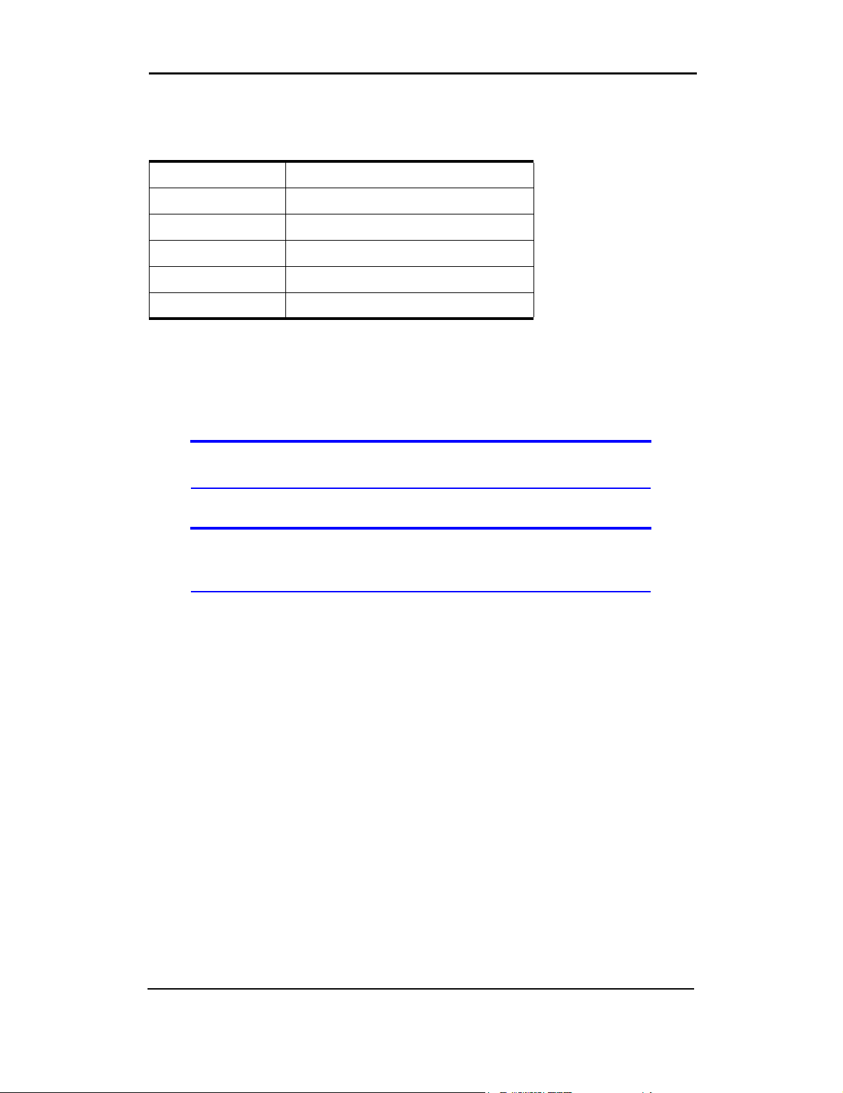
To install the PC3320 card, you require these system resources:
Table 4-1: System Resource Requirements
Card Slots 1 Type II PCMCIA (PC Card) Slot
Communications Ports 1 Available
Disk Drive CD-ROM (for installation only)
I/O Resources 1 IRQ, 40 bytes I/O Space
Memory 10 MB
Disk Space 2MB
PC3320 card software installation procedures
This section provides detailed installation instructions.
Note: A driver is software that provides the interface between a device (such as
the PC3320 card) and the operating system on your PC (such as Windows 98).
To install Mobile Connection Manager and the PC3320 card driver:
Note: Users of Windows 2000 must be logged in with administrative privileges to
install the PC3320 card software. Users of Windows XP may require administrative privileges, depending on the XP installation.
1. If the installation CD is not already in your CD-ROM drive, insert it. The CD should
autostart and display the Mobile Connection Manager Setup window.
If the CD does not autostart, select Start > Run and enter d:\launch.exe where d
is the drive letter of your CD-ROM drive.
2. From the CD startup window, select PC3320 Notebook Software Installation to launch
®
the InstallShield
3. Follow the instructions in the window, and click OK.
4. Use the Next and Back buttons to navigate through the wizard noting the following:
· You must click Yes to indicate your acceptance of the terms of the license
agreement to proceed with the installation.
· Use the default settings for the
ments and an advanced understanding of PC configuration.
5. If you are running Windows XP, a window indicates that the driver files will be copied
to your notebook. Click OK and click Continue Anyway on the Software Installation
window if it appears. The window may appear more than once; the PC3320 card is a
multifunction card.
Wizard.
Destination Folder unless you have special require-
18 2130361
Page 21

Installation
Note: Do not forcefully connect the antenna, or forcefully insert the PC3320 card.
This may damage connector pins. See page 20 for instructions on removing the
PC3320 card.
6. Click OK when you are prompted to insert the PC3320 card. Attach the antenna and
insert the PC3320 card into your PC Card slot (refer to page 20).
Note: For Windows 98, and Me Users: If your computer has a built-in network
adapter, your computer may appear to have stopped responding during the card
detection process. The operating system is resolving resource issues related to
your built-in adapter and the PC3320 card. Do not abort the installation
process. Allow several minutes for the process to complete.
7. If your operating system is Windows 98 or Me, restart your PC from the Start menu.
Note: Windows 98 and Me users: If your computer has a built-in network adapter,
another long delay occurs the first time the PC3320 card is inserted after this
restart. Subsequent insertions of the card will not experience this delay.
On completion of this step, Mobile Connection Manager and the PC3320 card
driver are installed.
You may now install the Venturi compression software if desired. See “Venturi™
Software Installation” on page 19.
Venturi™ Software Installation
To install the Venturi™ compression software:
Note: Users of Windows 2000 must be logged in with administrative privileges to
install the Venturi software. Users of Windows XP may require administrative
privileges, depending on the XP installation.
1. If the PC3320 Wireless Network Card screen is not displayed:
If the installation CD is already in your CD-ROM drive, select Start > Run and enter
d
:\launch.exe (where d is the drive letter of your CD-ROM drive) to display the startup
menu. Otherwise, insert the CD in your CD-ROM drive. (The CD should autostart and
display the menu.)
2. From the PC3320 Wireless Network Card screen, select Venturi Software Installation.
The InstallShield® Wizard starts.
3. Use the Next and Back buttons to navigate through the wizard noting the following:
· You must click Yes to indicate your acceptance of the terms of the license
agreement to proceed with the installation.
Rev 1.0 Mar.04 19
Page 22

Installation Guide
· Use the default settings for the Destination Location unless you have special
requirements and an advanced understanding of PC configuration. (The Destination Location dictates where the software is installed.)
· You must restart your PC before you can use the software. Click Finish to close the
last screen of the wizard and to restart your PC.
On completion of this step, the Venturi software is installed and, after your PC
reboots, you can proceed to configure the PC3320 card to use your account (if it
was not pre-activated). See “Activation” on page 21.
Card insertion and removal
Inserting the PC3320 card
To insert the PC3320 into a notebook:
1. Attach the antenna to the circular gold connector on the end of the PC3320 card. DO
NOT FORCE.
2. With the picture label facing up, insert the PC3320 card into the slot.
When you insert the PC3320, the following should occur:
• If sound effects are enabled, the PC beeps.
• The PC Card icon appears in the status area, if it is not already displayed for
another card, (and unless the feature has been disabled).
The PC3320 card is powered as soon as you insert it.
Removing the PC3320 card
To remove the PC3320 card:
1. Close Mobile Connection Manager if it is open.
2. Click the PC Card icon in the status area to display the option to stop the card.
3. Click “
4. If a dialog box appears notifying you that it is safe to remove the card, click OK.
5. Use the ejector to remove the PC3320 card from the slot. Do not pull the PC3320
Stop CDMA 1X Parent” (Windows 98, 2000, or Me) or “Safely remove CDMA 1X
Parent
” (Windows XP).
card out by the antenna.
20 2130361
Page 23

• Manual Activation
• Automated Activation
Account configuration procedures
The final step to making the PC3320 card operational is configuring it to use your
CDMA service provider account. The process of activation configures your
PC3320 with the required account parameters (phone number, etc.).
If you purchased a pre-activated PC3320 card, this step is not necessary. Once
the application software and driver are installed, the PC3320 card is ready for
use.
Note: The PC3320 can support two accounts (phone numbers), allowing, for
example, one account for business and another for personal use.
Otherwise, you must use the Activation Wizard to activate and configure your
account.
Activation Wizard
55: Activation
The Activation Wizard walks you through the process of configuring an account.
The process and options vary based on the service provider. The wizard supports
Automated Activation in addition to Manual Activation where the service provider
supports them.
This section is a guide only. Consult the Quick Start Guide, and follow the directions on screen and instructions given by your service provider representative.
To activate an account and configure your PC3320 card for use:
1. Attach the antenna and insert the PC3320 card into your PC Card slot (refer to
“Inserting the PC3320 card” on page 20).
2. Start Mobile Connection Manager by selecting:
Start > Programs > Verizon Wireless > Mobile Connection Manager
3. Mobile Connection Manager should detect that the PC3320 card has not been
activated and automatically start the Activation Wizard. If it does not start the wizard,
in Mobile Connection Manager select:
· Tools > Activation Wizard
4. The wizard presents a selection window, offering the activation methods supported by
your service provider:
· Manual Activation involves entering your account information into the appropriate
fields in the wizard using information from your package or product shipment.
· Automated Activation involves the PC3320 placing a call to a special number at
the service provider. Follow onscreen prompts.
Rev 1.0 Mar.04 21
Page 24

Installation Guide
5. To begin activation of the PC3320, select the method and click Next.
Manual activation
Verizon has provided the required information on your package or with the
product shipment.
1. Select the Manual Activation radio button and click Next.
2. The wizard prompts for your activation code.
Enter six zeroes (000000) then click Next.
3. Enter the phone number provided with your package. Enter the IMSI. Click Next.
4. Enter the SID (System ID) provided with your package. Click Next.
5. Click Finish on the final window of the wizard.
On completion, the PC3320 card is ready for use. The next chapter explains how
to use Mobile Connection Manager to manage and monitor your connections.
Automated activation
To use automated activation:
1. Select the Automated Activation radio button and click Next.
2. The wizard advises that it will make a network connection, dialing the displayed
number. Leave the number unchanged unless told by a technical service representative to enter a different value. Click Next.
3. Follow any instructions or prompts provided to activate the card.
Mobile Connection Manager displays the activation progress in the call status
area. When the process is complete you should see the message
Connect”. At this point your PC3320 card is ready to use. The next chapter
“Ready to
explains how to use Mobile Connection Manager to manage and monitor your
connections.
Note: If you do not get the “Ready to Connect” message, retry the process. If the
process continues to fail, use manual activation or contact your service provider.
22 2130361
Page 25

Manager™ Basics
• Starting and Closing Mobile Connection Manager
• Components of the Mobile Connection Manager Window
• Interpreting Icons
• Online Help
• Troubleshooting
Mobile Connection Manager is the application that allows you to manage and
monitor the connection between the PC3320 wireless network card and the
CDMA network. You use Mobile Connection Manager to:
• Determine your signal strength, roaming status, 1X high-speed data avail-
ability, and other network connection parameters
• Initiate data calls
• View call statistics
• Receive and send SMS messages
• Customize features and options
Anytime you use the PC3320 card you must run Mobile Connection Manager.
Once you make a connection in Mobile Connection Manager, you can launch
whatever application you want to use (such as your web browser or e-mail application).
66: Mobile Connection
Starting and closing Mobile Connection Manager
You can launch Mobile Connection Manager by:
• Double-clicking the Mobile Connection Manager icon on your desktop
• Selecting Start > Programs > Verizon Wireless > Mobile Connection Manager
The standard Windows control buttons in the upper right corner of the window are
used to minimize or close Mobile Connection Manager. When minimized, Mobile
Connection Manager does not appear as a taskbar button. Instead, an icon is
shown in the status area, usually at the right end of the taskbar. (See “Minimized
Icons” on page 28.)
Rev 1.0 Mar.04 23
Page 26

Installation Guide
Components of the Mobile Connection Manager window
The window has three areas that display messages and icons: the Connection
Status Area, Call Status Area, and Indicator Area.
The window allows you to connect and disconnect Internet and dial-up data
services.
A menu bar is located on the upper left side of the window.
Windows control buttons are in the top right corner.
Menu Bar
Toggle Full/Compact Button
Close ButtonMinimize Button
Connection Status Area
Call Status Area
Connection
Indicator Area
Figure 6-1: Mobile Connection Manager
For a detailed description of each option in the menus, see the online Help.
Window controls
• The Minimize button closes the Mobile Connection Manager window but
leaves the application running. When Mobile Connection Manager is
minimized, the Mobile Connection Manager icon in the status area can be
used to determine the PC3320 card status. (See page 28.) This icon replaces
a taskbar button for Mobile Connection Manager.
Once minimized, you can redisplay the Mobile Connection Manager window
by selecting the Mobile Connection Manager icon in the status area. You can
also restore the window by double-clicking the desktop shortcut or launching
Mobile Connection Manager from the Start menu.
Manager
Button
24 2130361
Page 27

Mobile Connection Manager™ Basics
• The Toggle Full/Compact button is used to switch between the full Mobile
Connection Manager window and the compact view:
The compact view allows you to see connection status and indicators while
using less space on the desktop.
You must use full view to make calls, data connections, disconnect, or access
Mobile Connection Manager features. To return to full view, select the view
toggle button in the top right.
• The Close button is used to exit Mobile Connection Manager.
Docking
You can set the Mobile Connection Manager window to “jump” to the edge of your
screen when you move the window close to an edge. This lets you easily position
Mobile Connection Manager in a corner of the screen.
• Select View > Docking
Always On Top
You can set Mobile Connection Manager to always display in front of other
windows. This allows you to monitor connection status while using another
maximized application, such as your web browser.
• Select View > Always On Top
Interpreting icons
Mobile Connection Manager makes extensive use of icons to indicate status and
events. The various icons are described in the following sections on the display
areas of Mobile Connection Manager.
Rev 1.0 Mar.04 25
Page 28

Installation Guide
Connection Status Area
Note: Optimal signal strength is obtained when the antenna is perpendicular to
the PC3320 card.
The Connection Status Area uses the icons shown in Table 6-1.
Table 6-1: Connection Status Area icons
Icon Meaning
The Signal Strength indicator uses bars to show the intensity of the
radio signal. The number of bars increases as signal strength increases
to a maximum of five bars.
When the bars are dimmed and the antenna icon is crossed out, no
connection is possible for one of these reasons:
• No antenna is attached
• You are outside the CDMA network coverage area
• The signal strength is too weak
• A network or account problem is preventing the PC3320 from
obtaining service
The 1X indicator shows whether 1X is available in this area.
The Roaming Status indicator shows whether you are roaming within a
The In Use indicator shows whether a call is in progress. No icon is displayed when the
PC3320 card is idle. Otherwise, one of these icons is displayed:
“preferred” roaming area.
When the indicator is off (gray), you are within the local coverage area
of your service provider. When the indicator is on (solid black), you are
in a “preferred” roaming area. When the indicator is blinking, you are
within the coverage area of a CDMA network but not in a “preferred”
roaming area.
Your coverage area and account charges depend upon your service
provider and the type of account you have. There may be surcharges
for roaming service that vary based on whether you are in a preferred or
non-preferred roaming area. If there is no roaming agreement between
your service provider and the local carrier, you may be unable to
complete calls.
A circuit switched data call is in progress.
26 2130361
Page 29

Mobile Connection Manager™ Basics
Table 6-1: Connection Status Area icons (cont.)
Icon Meaning
A high-speed (1X) packet data call is in progress.
A fatal error has occurred and the PC3320 card is inoperable. (This may
be resolved by closing Mobile Connection Manager and restarting your
PC.)
Call Status Area
The Call Status Area displays messages related to the status or progress of a
connection.
Where a duration timer is shown, timing begins when the call is initiated—not
from the time the call is fully connected. This is a measure of the time the PC3320
has been using the radio channel (a wireless network resource).
“
PowerSave - Click this display to exit” indicates that the PC3320 card could not find a
CDMA system within a 15 minute interval. To conserve power, the PC3320 card
reduces channel scanning to once every three minutes. To force the PC3320 card
out of PowerSave mode, click in the Call Status Area. The PC3320 card performs
a channel scan and, if no network is detected, returns to PowerSave mode.
Indicator area
The Indicator area displays icons that notify you when you receive messages and
indicate whether certain options and features are enabled. The icons are black
when “on” and gray when “off”.
Table 6-2: Indicator Area icons
Icon Meaning
The SMS message indicator shows whether you have
unread messages. A blinking icon indicates that there are
one or more urgent or important unread messages. To
display the Mobile Messenger window (in which the
messages are displayed) select
Messenger…
or double- click the icon.
Tools > Mobile
Rev 1.0 Mar.04 27
Page 30

Installation Guide
Minimized Icons
Mobile Connection Manager displays an icon in the Windows status area (which
is usually located in the lower right corner of your screen). The status area icon
indicates your connection status or notifies you when you have SMS messages.
Table 6-3: Status Area icons
Icon Meaning
You are not in service on the CDMA network.
You are in service on the CDMA network but have no
active data connection.
The number of red bars indicates the signal strength.
You have an active data connection.
The number of green bars indicates the signal
strength.
You have unread SMS message(s).
Only one icon can be displayed at a time. The priority of icons, from highest to
lowest, is:
• SMS message(s)
• Active or inactive connection.
For example, if you have unread SMS messages, and then establish a data
connection, the icon still displays as an unread SMS message.
Online Help
Mobile Connection Manager includes extensive online help to provide operating
hints and step-by-step instructions for getting the most from your PC3320
wireless network card.
You can access online help in several ways:
• Press <F1> in any window.
• Click the Hints button available in many windows.
• Use Windows Explorer to navigate to Program Files > Verizon Wireless >
Mobile Connection Manager > CM.chm
The help file has a table of contents and an index.
. Double-click to open the help file.
28 2130361
Page 31

Mobile Connection Manager™ Basics
Troubleshooting
The online help includes descriptions of most common error messages. Look in
the table of contents under Troubleshooting.
For help with other problems:
• Contact your service provider.
Rev 1.0 Mar.04 29
Page 32

Installation Guide
30 2130361
Page 33
• LED Operation
• Radio Frequency and Electrical Specifications
• Environmental Specifications
This chapter describes the function of the LED, and provides technical product
data for the PC3320 wireless network card.
LED operation
The PC3320 has a single red/green LED on the antenna end of the card. The
LED operates as follows:
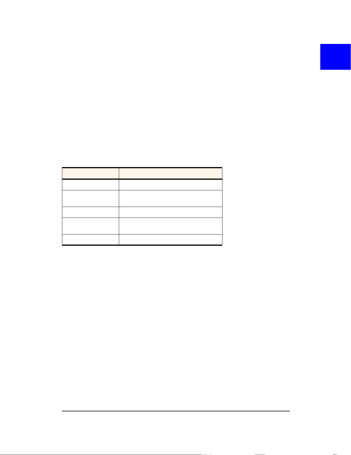
Table 7-1: LED operation
LED Behavior Indicates
Solid amber* The PC3320 card is powering up.
77: Technical Specifications
Blinking amber The PC3320 card is searching for a
Solid green A call is in progress.
Blinking green The PC3320 card has acquired a channel
Solid red An error has occurred.
* Amber is used to describe the color of the LED when both red and green are lit.
channel.
and is in idle mode (no call is in progress).
Rev 1.0 Mar.04 31
Page 34
Installation Guide
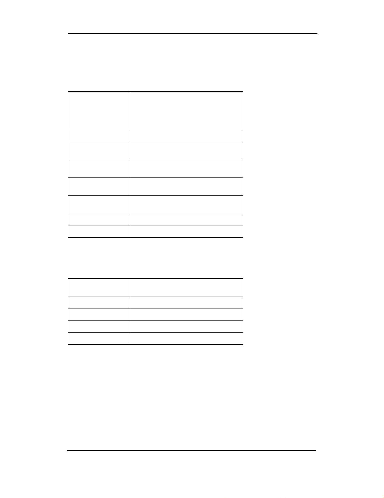
Radio frequency and electrical specifications
Table 7-2: Radio frequency and electrical specifications
Approvals Compliant with:
IS-95A, IS-95B, IS-98D, IS-707A,
IS707A-1, CDMA Developers Group
FCC (ID: N7NACRD555)
Industry Canada
Vol tage +5 Vdc from PCMCIA Slot
Current Maximum: 680 mA
Typical: 150 mA
Transmitter
Power
Transmit PCS: 1850 to 1910 MHz
Receive PCS: 1930 to 1990 MHz
Channel Spacing 1.25 MHz
Freq. Stability ±150 Hz
200 mW (+23 dBm)
Cellular: 824 to 849 MHz
Cellular: 869 to 894 MHz
Environmental specifications
Table 7-3: Environmental specifications
Operating Temp. -30 to +60°C (ambient, outside PCMCIA
enclosure)
Storage Temp. -30 to +85°C
Humidity 95%, non-condensing
Vibration 15 g peak 10 to 2000 Hz (non-operating)
Drop 30” (76.2 cm) on to vinyl covered concrete
32 2130361
Page 35

Appendix A: Glossary
1X
One Times Radio Transmission Technology (the "one times" refers to the frequency
spectrum)
bps
bits per second—The actual data speed over the transmission medium. See also
baud.
CDMA
Code Division Multiple Access—A wideband spread spectrum technique used in
digital cellular, personal communications services, and other wireless networks.
Wide channels (1.25 MHz) are obtained through spread spectrum transmissions,
thus allowing many active users to share the same channel. Each user is assigned
a unique digital code, which differentiates the individual conversations on the same
channel.
CDMA 1X
Also known as 1X, this is a high-speed standard for CDMA cellular communications.
circuit switched cellular
V.xx modem communications over a cellular network. It uses a dedicated
connection circuit, in contrast to packet-switched. The user is charged by the
carrier for the duration of the connection.
ESN
Electronic Serial Number—The unique serial number assigned to the modem for
cellular network use.
FCC
Federal Communications Commission—The U.S. federal agency that is respon-
sible for interstate and foreign communications. The FCC regulates commercial and
private radio spectrum management, sets rates for communications services, determines standards for equipment, and controls broadcast licensing. Consult
www.fcc.gov.
Rev 1.0 Mar.04 33
Page 36

Installation Guide
host
1. A computer that uses a modem or a similar device to answer a calling computer.
2. A source or destination in the communication network.
3. A computer that contains data or files to be accessed by client computers. Also
known as a server.
IMSI
International Mobile Station Identity—A 15-digit number used to identify the
mobile device to the base station.
IS
Interim Standard—After receiving industry consensus, the TIA forwards the
standard to ANSI for approval.
IS-95
The standard for CDMA.
kbps
kilobits per second—Actually 1000, not 1024, as used in computer memory size
measurements of kilobytes.
LED
Light Emitting Diode—A semiconductor diode that emits visible or infrared light.
MHz
Mega-Hertz—One million cycles per second.
packet
A short fixed-length block of data including a header that is transmitted as a unit in a
communications network.
PC Card™
Add-in memory and communications cards for portable computers. PC Card is a
trademark of the PCMCIA.
PCMCIA
Personal Computer Memory Card International Association—The organization
that standardizes PC Cards.
34 2130361
Page 37

PCS
Personal Communications Services—A cellular communication infrastructure
that uses a different frequency range than AMPS.
QNC
Quick Net Connect—A CDMA connection method that reduces call setup time for
circuit switched connections to the Internet.
roaming
A cellular subscriber is in an area where service is obtained from a cellular service
provider that is not the subscriber’s provider.
SMS
Short message services—A feature that allows users of a wireless device on a
wireless network to receive or transmit short electronic alphanumeric messages (up
to 160 characters, depending on the service provider).
Glossary
TIA
Telecommunications Industry Association—A standards setting trade organi-
zation, whose members provide communications and information technology
products, systems, distribution services and professional services in the United
States and around the world. Consult
www.tiaonline.org.
Rev 1.0 Mar.04 35
Page 38

Installation Guide
36 2130361
Page 39

Index
Numerics
1X, 8, 10
indicator, 26
A
account
activation, 15
configuration, 21
activation
automated, 22
manual, 22
Activation Wizard, 21
always on top, 25
antenna
care and maintenance, 13
C
call status area, 27
care and maintenance, 13
CDMA network
frequency bands, 10
service providers, 10
circuit switched data, 8
close button, 25
compact view, 25
connection status
indicator, 28
connection status area, 26
coverage, 11
D
data
circuit switched, 8
dial-up, 8
high-speed, 8
Quick 2 Net, 8
dial-up data, 8
disk space
notebooks, 18
docking, 25
drivers
description, 10
F
frequency bands, CDMA network, 10
full view
description, 24
toggle button, 25
H
help, 28
high-speed packet data, 8
I
I/O space (input/output space), 18
icons
connection status, 26
indicator area, 27
minimized, 28
in use indicator, 26
indicator area, 27
indicators
connection status, 28
SMS messages, 27, 28
inserting the PC3320, 20
installation, 18
Internet, 8, 8
IRQ (interrupt request), 18
IS-95, 10
M
memory
notebooks, 18
minimize button, 24
minimized icons, 28
Mobile Connection Manager, 10
N
NationalAccess high-speed packet data, 8
not in service indicator, 28
notebooks
installing the software, 17– 20
removing the PC3320, 20
E
ESN, 16
O
online Help, 28
operating hints, 28
Rev 1.0 Mar.04 37
Page 40

Index
P
PowerSave, 27
pre-activation, 15
Q
Quick 2 Net, 8
R
removing the PC3320, 20
roaming
definition, 11
indicator, 26
S
signal strength
indicator, 26
obtaining optimal, 13
SMS message indicator, 27, 28
software, 10
software installation, 17– 20
system requirements
notebooks, 17
T
taskbar icons, 28
troubleshooting, 29
38 2130361
 Loading...