

Page 1

oMG
Operation and Configuration
Guide 3.14
4118618
Rev 4
Page 2

Operation and Configuration Guide 3.14
Important
Notice
Safety and
Hazards
Due to the nature of wireless communications, transmission and reception of data can
never be guaranteed. Data may be delayed, corrupted (i.e., have errors) or be totally
lost. Although significant delays or losses of data are rare when wireless devices such
as the Sierra Wireless modem are used in a normal manner with a well-constructed
network, the Sierra Wireless modem should not be used in situations where failure to
transmit or receive data could result in damage of any kind to the user or any other
party, including but not limited to personal injury, death, or loss of property. Sierra
Wireless accepts no responsibility for damages of any kind resulting from delays or
errors in data transmitted or received using the Sierra Wireless modem, or for failure
of the Sierra Wireless modem to transmit or receive such data.
Do not operate the Sierra Wireless modem in areas where blasting is in progress,
where explosive atmospheres may be present, near medical equipment, near life
support equipment, or any equipment which may be susceptible to any form of radio
interference. In such areas, the Sierra Wireless modem MUST BE POWERED OFF.
The Sierra Wireless modem can transmit signals that could interfere with this
equipment.
Do not operate the Sierra Wireless modem in any aircraft, whether the aircraft is on
the ground or in flight. In aircraft, the Sierra Wireless modem MUST BE POWERED
OFF. When operating, the Sierra Wireless modem can transmit signals that could
interfere with various onboard systems.
Note: Some airlines may permit the use of cellular phones while the aircraft is on the ground
and the door is open. Sierra Wireless modems may be used at this time.
Limitation of
Liability
The driver or operator of any vehicle should not operate the Sierra Wireless modem
while in control of a vehicle. Doing so will detract from the driver or operator's control
and operation of that vehicle. In some states and provinces, operating such
communications devices while in control of a vehicle is an offence.
The information in this manual is subject to change without notice and does not
represent a commitment on the part of Sierra Wireless. SIERRA WIRELESS AND ITS
AFFILIATES SPECIFICALLY DISCLAIM LIABILITY FOR ANY AND ALL DIRECT,
INDIRECT, SPECIAL, GENERAL, INCIDENTAL, CONSEQUENTIAL, PUNITIVE OR
EXEMPLARY DAMAGES INCLUDING, BUT NOT LIMITED TO, LOSS OF PROFITS
OR REVENUE OR ANTICIPATED PROFITS OR REVENUE ARISING OUT OF THE
USE OR INABILITY TO USE ANY SIERRA WIRELESS PRODUCT, EVEN IF
SIERRA WIRELESS AND/OR ITS AFFILIATES HAS BEEN ADVISED OF THE
POSSIBILITY OF SUCH DAMAGES OR THEY ARE FORESEEABLE OR FOR
CLAIMS BY ANY THIRD PARTY.
Notwithstanding the foregoing, in no event shall Sierra Wireless and/or its affiliates
aggregate liability arising under or in connection with the Sierra Wireless product,
regardless of the number of events, occurrences, or claims giving rise to liability, be in
excess of the price paid by the purchaser for the Sierra Wireless product.
Rev 4 May.17 2 4118618
Page 3

Preface
Patents This product may contain technology developed by or for Sierra Wireless Inc. This
product includes technology licensed from QUALCOMM
manufactured or sold by Sierra Wireless Inc. or its affiliates under one or more
patents licensed from InterDigital Group and MMP Portfolio Licensing.
®
. This product is
Copyright © 2017 Sierra Wireless. All rights reserved.
Trademarks Sierra Wireless
registered trademarks of Sierra Wireless, Inc.
Windows
QUALCOMM
license.
Other trademarks are the property of their respective owners.
®
, AirPrime®, AirLink®, AirVantage® and the Sierra Wireless logo are
®
and Windows Vista® are registered trademarks of Microsoft Corporation.
®
is a registered trademark of QUALCOMM Incorporated. Used under
Contact
Information
Sales information and technical
support, including warranty and returns
Corporate and product information Web: sierrawireless.com
Web: sierrawireless.com/company/contact-us/
Global toll-free number: 1-877-687-7795
6:00 am to 6:00 pm PST
Revision
History
Revision
number
1 May 2016 Imported content from oMG-ED-121006 r4.9
2 September 2016 Added Pilot Ping field to WAN Configuration screens
3 January 2017 DFS channels re-enabled, so removed rev2 note concerning removal of Wi-Fi
4 May 2017 Replaced ‘oCM’ and ‘oMM’ references with ‘ACM’ and ‘AMM’
Release date Changes
Added topic Accessing the Console on page 57
Updated MTBF
Added Configuring DNS Zones for Private DNS Server Use and updated Automatic
DNS field descriptions
Noted removal of Wi-Fi channels to comply with FCC rules
Noted special character restriction for Pre-Shared Key format
Updated Server List format for Remote Forwarding
channels.
Updated section NMEA Messaging ‘Additional Options’—changed label for ESN
option, added option to group sentences
Updated Auto Software Updates options
Rev 4 May.17 3 4118618
Page 4

Contents
1: Overview . . . . . . . . . . . . . . . . . . . . . . . . . . . . . . . . . . . . . . . . . . . . . . . . . . . . .8
1.1 Who Should Read This Guide . . . . . . . . . . . . . . . . . . . . . . . . . . . . . . . . . 8
1.2 What is the oMG. . . . . . . . . . . . . . . . . . . . . . . . . . . . . . . . . . . . . . . . . . . . 8
1.3 Pre-Installation Requirements . . . . . . . . . . . . . . . . . . . . . . . . . . . . . . . . . 9
1.4 Related Publications. . . . . . . . . . . . . . . . . . . . . . . . . . . . . . . . . . . . . . . . . 9
2: Powering the oMG On and Off . . . . . . . . . . . . . . . . . . . . . . . . . . . . . . . . . .10
2.1 Powering On. . . . . . . . . . . . . . . . . . . . . . . . . . . . . . . . . . . . . . . . . . . . . . 10
2.2 Powering Off. . . . . . . . . . . . . . . . . . . . . . . . . . . . . . . . . . . . . . . . . . . . . . 10
3: Accessing the Configuration Settings . . . . . . . . . . . . . . . . . . . . . . . . . . . .11
3.1 Viewing the Configuration Settings . . . . . . . . . . . . . . . . . . . . . . . . . . . . 12
4: Preparing the Network Interfaces . . . . . . . . . . . . . . . . . . . . . . . . . . . . . . . .13
5: Setting up the WAN . . . . . . . . . . . . . . . . . . . . . . . . . . . . . . . . . . . . . . . . . . .14
5.1 Basic WAN Link Configuration. . . . . . . . . . . . . . . . . . . . . . . . . . . . . . . . 14
5.1.1 Cellular WAN Link Configuration . . . . . . . . . . . . . . . . . . . . . . . . . .15
5.1.2 WiFi WAN Link Configuration . . . . . . . . . . . . . . . . . . . . . . . . . . . . .16
5.1.3 Ethernet WAN Link Configuration . . . . . . . . . . . . . . . . . . . . . . . . . .16
5.1.4 Serial WAN Link Configuration . . . . . . . . . . . . . . . . . . . . . . . . . . . .17
5.2 Defining an Access Point Profile for WiFi Links . . . . . . . . . . . . . . . . . . . 18
5.3 Maintaining Communications with Services of a WAN. . . . . . . . . . . . . . 19
5.4 Setting up a Link Policy . . . . . . . . . . . . . . . . . . . . . . . . . . . . . . . . . . . . . 22
5.4.1 Special Considerations for WiFi Links . . . . . . . . . . . . . . . . . . . . . .23
5.4.2 Dynamic Priority Policy Overview . . . . . . . . . . . . . . . . . . . . . . . . . .23
5.4.3 Geographical Regions Policy Overview . . . . . . . . . . . . . . . . . . . . .26
5.4.4 Time Period Policy Overview . . . . . . . . . . . . . . . . . . . . . . . . . . . . .27
5.4.5 Velocity Policy Overview . . . . . . . . . . . . . . . . . . . . . . . . . . . . . . . . .28
5.4.6 Signal Strength Policy Overview . . . . . . . . . . . . . . . . . . . . . . . . . . .29
5.4.7 Use Cases . . . . . . . . . . . . . . . . . . . . . . . . . . . . . . . . . . . . . . . . . . .29
Rev 4 May.17 4 4118618
Page 5

Contents
5.5 Setting up Firewall Rules. . . . . . . . . . . . . . . . . . . . . . . . . . . . . . . . . . . . 31
5.5.1 Configuring the WAN Rule Firewall Settings . . . . . . . . . . . . . . . . . 31
5.5.2 Deleting WAN Rules . . . . . . . . . . . . . . . . . . . . . . . . . . . . . . . . . . . . 31
5.5.3 Recovering from Dead WAN Connections . . . . . . . . . . . . . . . . . . . 31
6: Setting up the LAN . . . . . . . . . . . . . . . . . . . . . . . . . . . . . . . . . . . . . . . . . . . . 33
6.1 Configuring LAN Access . . . . . . . . . . . . . . . . . . . . . . . . . . . . . . . . . . . . 33
6.2 Configuring LAN Segments. . . . . . . . . . . . . . . . . . . . . . . . . . . . . . . . . . 34
6.3 Configuring DHCP and Static IP Addresses . . . . . . . . . . . . . . . . . . . . . 36
6.4 Setting up the LAN Firewall. . . . . . . . . . . . . . . . . . . . . . . . . . . . . . . . . . 36
6.4.1 Configuring the LAN Rule Firewall Settings . . . . . . . . . . . . . . . . . . 36
6.4.2 Deleting a LAN Network Rules: . . . . . . . . . . . . . . . . . . . . . . . . . . . 37
6.5 Attaching a Network Printer. . . . . . . . . . . . . . . . . . . . . . . . . . . . . . . . . . 37
6.6 Setting up Virtual LANs . . . . . . . . . . . . . . . . . . . . . . . . . . . . . . . . . . . . . 38
7: How to Configure a VPN . . . . . . . . . . . . . . . . . . . . . . . . . . . . . . . . . . . . . . . 39
7.1 Detecting Dead VPN Connections. . . . . . . . . . . . . . . . . . . . . . . . . . . . . 40
7.2 Multi-VPN Support. . . . . . . . . . . . . . . . . . . . . . . . . . . . . . . . . . . . . . . . . 41
7.3 Configuring DNS Zones for Private DNS Server Use . . . . . . . . . . . . . . 43
8: Setting up GPS Connectivity . . . . . . . . . . . . . . . . . . . . . . . . . . . . . . . . . . . 44
9: Performance Tuning . . . . . . . . . . . . . . . . . . . . . . . . . . . . . . . . . . . . . . . . . . 47
9.1 Configuring Load balancing. . . . . . . . . . . . . . . . . . . . . . . . . . . . . . . . . . 47
9.2 Setting Quality of Service (QoS) . . . . . . . . . . . . . . . . . . . . . . . . . . . . . . 47
9.3 Configuring LAN Throughput Reporting Frequency . . . . . . . . . . . . . . . 48
10: Configuring the oMG's startup and shutdown Behavior . . . . . . . . . . . . 50
11: Administration . . . . . . . . . . . . . . . . . . . . . . . . . . . . . . . . . . . . . . . . . . . . . . 52
11.1 Obtaining General Information. . . . . . . . . . . . . . . . . . . . . . . . . . . . . . . 52
11.2 Obtaining Network Status . . . . . . . . . . . . . . . . . . . . . . . . . . . . . . . . . . 52
Rev 4 May.17 5 4118618
Page 6

Operation and Configuration Guide 3.14
11.3 Configuring User Access. . . . . . . . . . . . . . . . . . . . . . . . . . . . . . . . . . . 53
11.4 Changing the Root Password . . . . . . . . . . . . . . . . . . . . . . . . . . . . . . . 54
11.5 Backing up and Restoring Configuration Settings. . . . . . . . . . . . . . . . 54
11.6 Configuring Services . . . . . . . . . . . . . . . . . . . . . . . . . . . . . . . . . . . . . . 55
11.7 Using the Diagnostic Tools . . . . . . . . . . . . . . . . . . . . . . . . . . . . . . . . . 56
11.8 Running Custom Scripts . . . . . . . . . . . . . . . . . . . . . . . . . . . . . . . . . . . 56
11.9 Accessing the Console . . . . . . . . . . . . . . . . . . . . . . . . . . . . . . . . . . . . 57
12: Applications . . . . . . . . . . . . . . . . . . . . . . . . . . . . . . . . . . . . . . . . . . . . . . . . 58
13: Updating the System . . . . . . . . . . . . . . . . . . . . . . . . . . . . . . . . . . . . . . . . . 59
13.1 Configuring Auto Software Updates . . . . . . . . . . . . . . . . . . . . . . . . . . 59
13.2 Over the Air Updates. . . . . . . . . . . . . . . . . . . . . . . . . . . . . . . . . . . . . . 61
14: Troubleshooting . . . . . . . . . . . . . . . . . . . . . . . . . . . . . . . . . . . . . . . . . . . . . 62
14.1 Viewing Advanced System Event Information. . . . . . . . . . . . . . . . . . . 62
A: Configuration Settings . . . . . . . . . . . . . . . . . . . . . . . . . . . . . . . . . . . . . . . . 64
A.1 Policies . . . . . . . . . . . . . . . . . . . . . . . . . . . . . . . . . . . . . . . . . . . . . . . . . 64
A.1.1 Dynamic Priority Policy . . . . . . . . . . . . . . . . . . . . . . . . . . . . . . . . . 64
A.1.2 Geographic Region Policy . . . . . . . . . . . . . . . . . . . . . . . . . . . . . . . 64
A.1.3 Time Period Policy . . . . . . . . . . . . . . . . . . . . . . . . . . . . . . . . . . . . . 64
A.1.4 Velocity Policy . . . . . . . . . . . . . . . . . . . . . . . . . . . . . . . . . . . . . . . . 65
A.1.5 Signal Strength Policy . . . . . . . . . . . . . . . . . . . . . . . . . . . . . . . . . . 65
A.2 Networking Rules . . . . . . . . . . . . . . . . . . . . . . . . . . . . . . . . . . . . . . . . . 65
A.2.1 Access Blocking . . . . . . . . . . . . . . . . . . . . . . . . . . . . . . . . . . . . . . . 65
A.2.2 Access Granting . . . . . . . . . . . . . . . . . . . . . . . . . . . . . . . . . . . . . . . 66
A.2.3 Port Forwarding . . . . . . . . . . . . . . . . . . . . . . . . . . . . . . . . . . . . . . . 66
A.2.4 QoS Priority . . . . . . . . . . . . . . . . . . . . . . . . . . . . . . . . . . . . . . . . . . 67
Rev 4 May.17 6 4118618
Page 7

Contents
A.3 WAN Link Configuration Settings . . . . . . . . . . . . . . . . . . . . . . . . . . . . . 68
A.3.1 Cellular WAN Link Configuration Settings . . . . . . . . . . . . . . . . . . . 68
A.3.2 WiFi Link Configuration Settings . . . . . . . . . . . . . . . . . . . . . . . . . . 71
A.3.3 Ethernet Link Configuration Settings . . . . . . . . . . . . . . . . . . . . . . . 72
A.3.4 TTY Serial Port Link Configuration Settings . . . . . . . . . . . . . . . . . 74
A.4 WAN Monitor Settings. . . . . . . . . . . . . . . . . . . . . . . . . . . . . . . . . . . . . . 76
A.5 WiFi Networks Configuration. . . . . . . . . . . . . . . . . . . . . . . . . . . . . . . . . 76
A.6 LAN Settings . . . . . . . . . . . . . . . . . . . . . . . . . . . . . . . . . . . . . . . . . . . . . 80
A.6.1 Access Point Settings . . . . . . . . . . . . . . . . . . . . . . . . . . . . . . . . . . 80
A.6.2 LAN Segment Settings . . . . . . . . . . . . . . . . . . . . . . . . . . . . . . . . . . 83
A.6.3 VLAN Settings . . . . . . . . . . . . . . . . . . . . . . . . . . . . . . . . . . . . . . . . 84
A.6.4 LAN Ethernet 802.1x Settings . . . . . . . . . . . . . . . . . . . . . . . . . . . . 84
A.7 LAN Throughput Settings . . . . . . . . . . . . . . . . . . . . . . . . . . . . . . . . . . . 84
A.8 WAN Recovery Settings . . . . . . . . . . . . . . . . . . . . . . . . . . . . . . . . . . . . 85
A.9 VPN Configuration Settings. . . . . . . . . . . . . . . . . . . . . . . . . . . . . . . . . . 85
A.10 Bluetooth Support . . . . . . . . . . . . . . . . . . . . . . . . . . . . . . . . . . . . . . . . 88
A.10.1 Supported Adaptors . . . . . . . . . . . . . . . . . . . . . . . . . . . . . . . . . . . 88
A.10.2 Configuration . . . . . . . . . . . . . . . . . . . . . . . . . . . . . . . . . . . . . . . . 89
A.11 GPS Configuration Settings . . . . . . . . . . . . . . . . . . . . . . . . . . . . . . . . 89
A.12 General Configuration Settings. . . . . . . . . . . . . . . . . . . . . . . . . . . . . . 91
A.12.1 Startup . . . . . . . . . . . . . . . . . . . . . . . . . . . . . . . . . . . . . . . . . . . . . 91
A.12.2 Shutdown . . . . . . . . . . . . . . . . . . . . . . . . . . . . . . . . . . . . . . . . . . . 91
A.12.3 Tools . . . . . . . . . . . . . . . . . . . . . . . . . . . . . . . . . . . . . . . . . . . . . . 92
A.12.4 Advanced Routing Rules . . . . . . . . . . . . . . . . . . . . . . . . . . . . . . . 93
A.12.5 Auto Software Updates . . . . . . . . . . . . . . . . . . . . . . . . . . . . . . . . 93
B: Technical Information . . . . . . . . . . . . . . . . . . . . . . . . . . . . . . . . . . . . . . . . . 96
B.1 Technical Specifications . . . . . . . . . . . . . . . . . . . . . . . . . . . . . . . . . . . . 96
B.2 LED Blink Patterns . . . . . . . . . . . . . . . . . . . . . . . . . . . . . . . . . . . . . . . . 99
C: Supported USB-To-Serial Adaptors . . . . . . . . . . . . . . . . . . . . . . . . . . . . 101
Rev 4 May.17 7 4118618
Page 8
1: Overview
This document provides operation and configuration instructions for the oMG running
software version 3.14.
1.1 Who Should Read This Guide
IT specialists who configure and oversee usage of the oMG should read this guide.
This guide contains common configuration tasks, while the appendices contain
detailed information on the available configuration options.
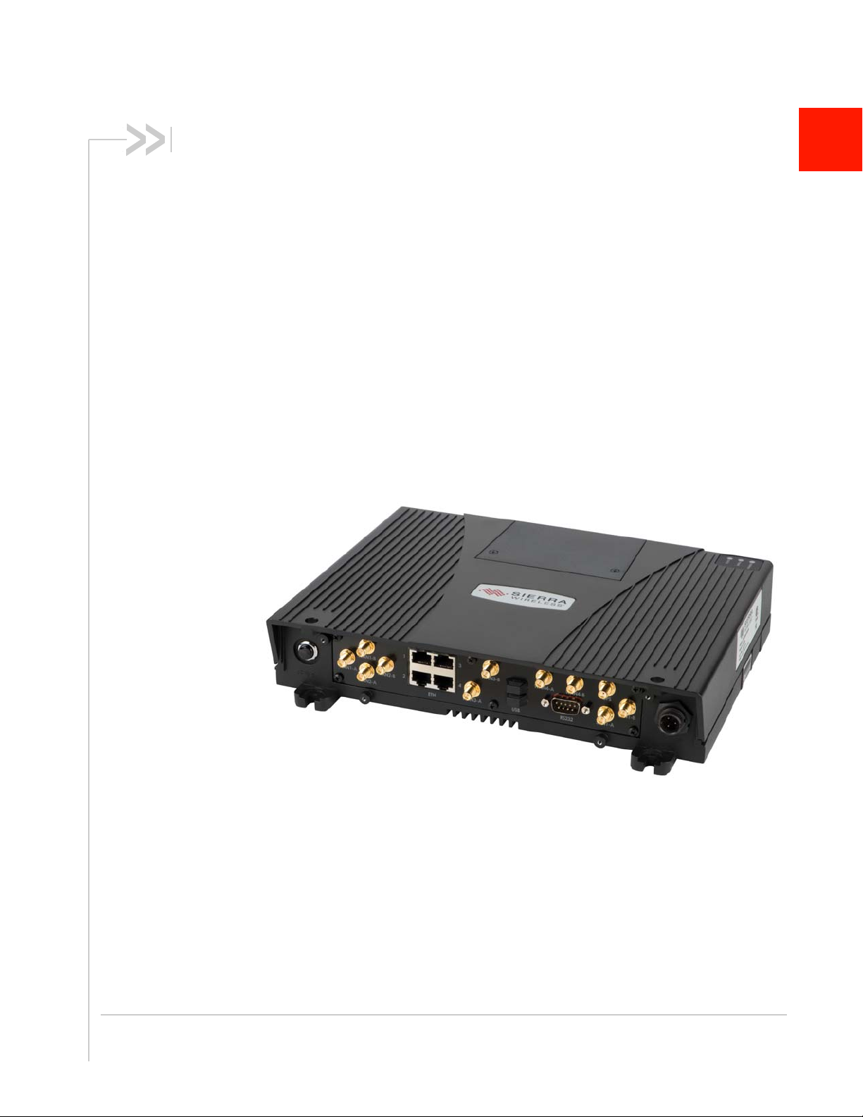
1.2 What is the oMG
The oMG is a ruggedized wireless gateway, designed for use in harsh mobile and
portable environments. The gateway extends the utility and convenience of LAN
networking to devices and applications in vehicles. The oMG interfaces with the AMM,
Sierra Wireless’ mobile network management system.
1
Figure 1-1: The back panel of an oMG
Key Features of the oMG:
• works in conjunction with the AMM to transmit data such as GPS, telemetry,
GPIO, and asset tracking information
• supports customization through the installation of select applications (purchased
separately) which tailor the unit to the needs of a fleet
• supports a variety of network interfaces including Ethernet, USB, Bluetooth,
Serial, a wide range of 802.11 WiFi/frequencies, 3G cellular networks, and LTE
networks
• supports network redundancy through multiple network interface installations
Rev 4 May.17 8
Page 9

Overview
• supports DHCP and static IPs
• provides high security through technologies like ESP, authentication,
encryption, firewall etc.
• supports VLANs and VPNs
1.3 Pre-Installation Requirements
This manual assumes that the appropriate cellular modem card is already
installed in the oMG base unit and that the cellular network provider has activated
the card.
In some cases, the cellular modem card may be pre-installed at the factory prior
to shipping. If a network card must be installed, please read the oMG Installation
and Configuration Guide for your model of oMG.
1.4 Related Publications
Table 1-1: Related Publications
Title and Publication Number Description
oMG 2000 Quick Setup Guide Describes how to quickly setup the oMG for
oMG 2000 Installation Guide Describes how to install the oMG in a vehicle.
Application Configuration
Guide
Passenger WiFi Application
Configuration Guide
basic operation.
Describes how to configure the oMG to work with
optional applications.
Describes how to configure the oMG's
passenger WiFi settings including customization
of the web portal.
Rev 4 May.17 9
Page 10

2: Powering the oMG On and Off
2.1 Powering On
The oMG has a factory default configuration that enables it to establish a WAN
connection if a cellular modem is installed along with an appropriate SIM card, and
the APN is configured correctly. Note that additional configuration is always
recommended.
Start the unit using the following steps:
1. Apply power to the system: if the oMG has been installed and wired into a
vehicle’s electrical system, turn on the ignition. If the oMG is not in a vehicle, an
optional AC power adaptor can also be used to supply 12V-DC power to the
system.
2. Turn on the unit: by default the oMG should start up automatically once it receives
power. If it does not, press the reset button on the back of the unit. Once power
up is complete the amber and green LED's will remain solid. For more information
on the LED patterns see LED Blink Patterns on page 99.
3. Test the unit: connect a test device such as a PC, equipped with Ethernet or WiFi,
to the oMG LAN. An oMG with factory default settings will provide an unsecured
WiFi access point (AP) broadcasting its own Serial Number as the SSID (e.g.
H100109D0002) and will also provide LAN access using Ethernet ports 1 to 3.
2
1
Once these steps have been completed, the oMG is ready for use, however further
configuration of the unit should be performed using the sections provided in this
document.
2.2 Powering Off
When powering down the unit, ensure that at least three minutes have elapsed since
the unit’s green Status light began to blink or at least two minutes have elapsed since
the light went solid.
This is necessary to ensure proper preparation of configuration files, in particular,
upon the first boot after a factory reset which takes longer than normal to prepare
these files. If this process is interrupted by a premature shutdown and/or removal of
power from the oMG, the process will repeat on subsequent boots until it is
successfully completed.
1. oMG 1000 series has only one Ethernet Port
Rev 4 May.17 10
Page 11
3: Accessing the Configuration Settings
The oMG Local Configuration Interface (LCI) is the oMG's browser-based
configuration utility which organizes the various configuration pages under a series of
tabs and sub tabs.
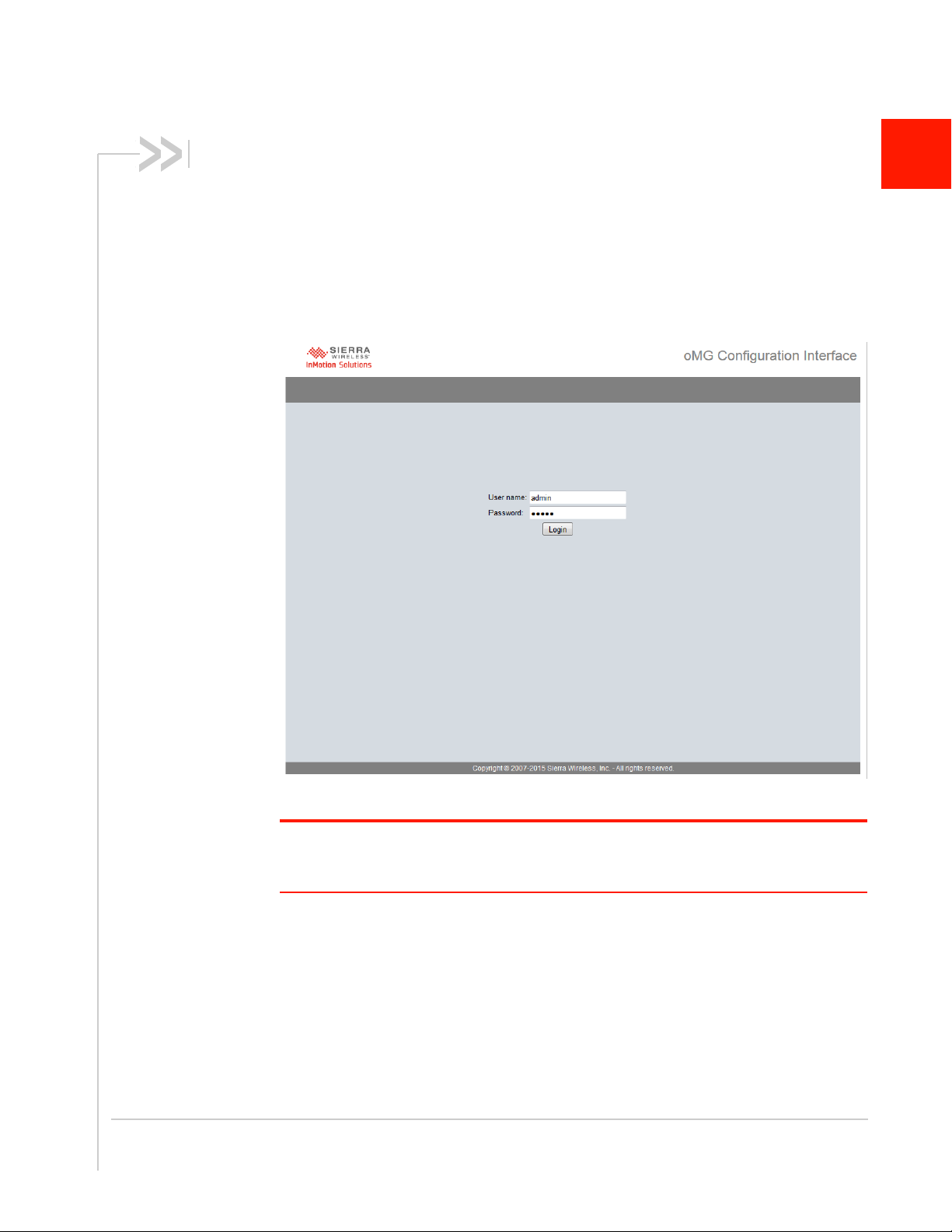
To access the LCI, navigate to the following URL using a web browser:
http://welcome.to.inmotion/MG-LCI. If this URL is not reachable, try entering:
172.22.0.1/MG-LCI. This will display the LCI login screen:
3
Figure 3-1: LCI Login Panel
Note: Configuration of the unit is best performed using a web browser running on a Windows 7
or Windows XP PC. As of version 3.8, the oMG supports Internet Explorer 9. Other devices and
other browsers may work but have not been certified by Sierra Wireless.
Log in using the following default credentials:
• User Name: admin
• Password: admin
Most configuration settings take effect immediately. However those related to the use
of the serial port only take effect after reboot.
The browser’s Forward and Back arrows can be used to navigate through the LCI.
Note that unless the Save button is clicked after making configuration changes, the
changes will not be saved and applied.
Rev 4 May.17 11
Page 12
Operation and Configuration Guide 3.14
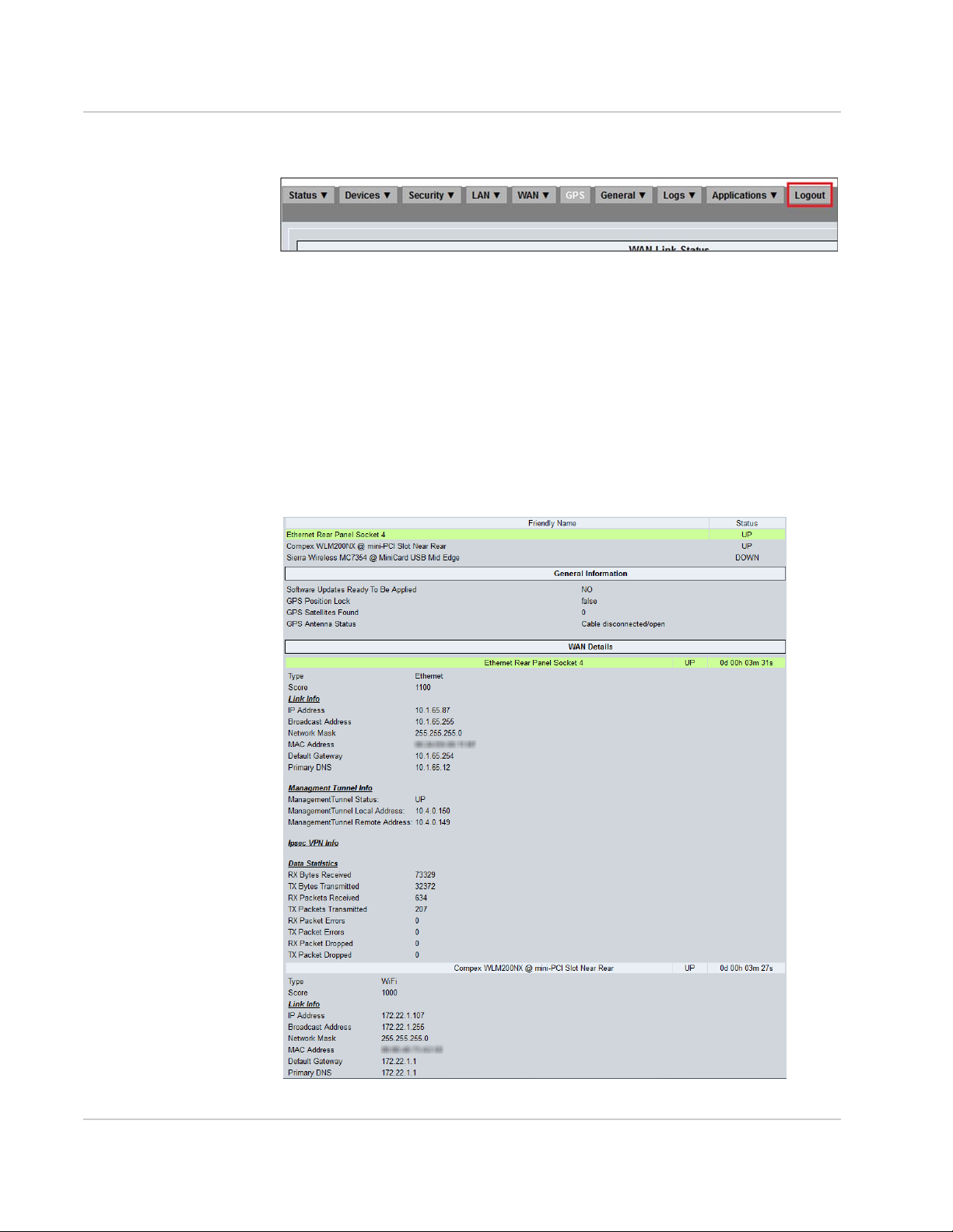
To log out of the LCI, click on the Logout tab which will log out the current user
and return to the login screen:
Figure 3-2: Using the Logout tab to log out of the system
3.1 Viewing the Configuration Settings
The oMG includes an Easy Access page, which allows users on all devices
connected to the unit to view the unit’s operational status without having to log
into the unit.
To view the Easy Access page from a device (e.g. laptop) connected to the unit,
navigate to the following URL using a web browser:
http://welcome.to.inmotion/MG-LCI/easyaccess.html.
This will display a read-only page showing the oMG’s operational status:
Figure 3-3: Easy Access Page
12 4118618
Page 13
4: Preparing the Network Interfaces
By default the oMG comes pre configured with devices which can provide both WAN
and LAN connectivity. It's recommended that the settings for each device be verified
before using the oMG. This will help to ensure that each device has been recognized
by the system and is properly configured to provide LAN or WAN data
communications.
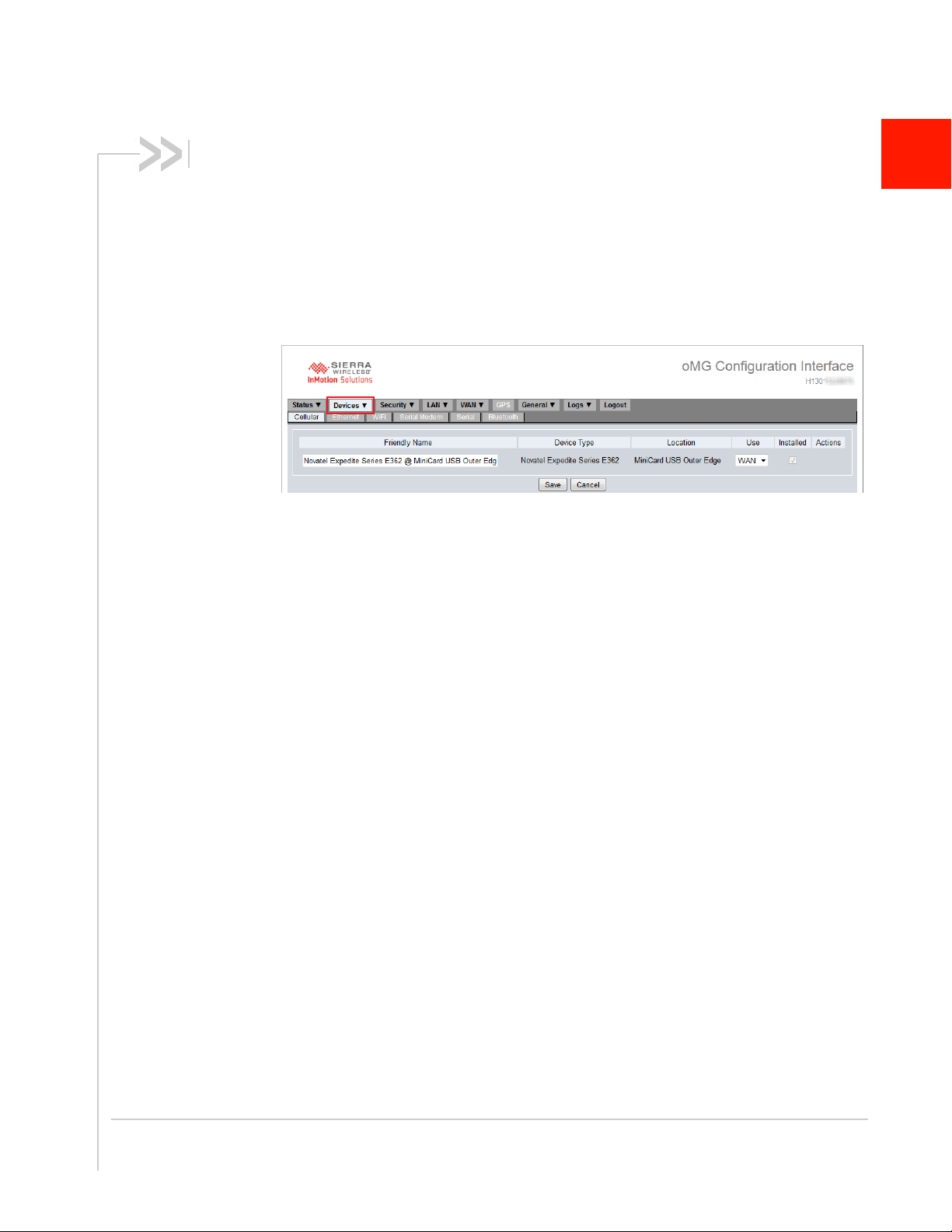
To view device settings, navigate to the Devices tab in the LCI:
Figure 4-1: An example of a Cellular Device on the Device Configuration Tab
A custom/descriptive name can be entered into the Friendly Name field. This can be
useful for example, to identify which access point the device will be used for.
Access the sub tabs to set each of the networking devices available on the oMG for
WAN or LAN usage:
• Cellular: cellular connectivity is the most common method for accessing the WAN
when an oMG is outside of a depot. Verify that the Installed field is checked for
each device listed on the Cellular tab and that the Use field has been set to WAN
for at least one of the devices listed.
• Ethernet: verify that the Installed field is checked for each Ethernet port listed.
· Optional: if Ethernet is to be used for LAN devices, ensure that the Use field
has been set to LAN for at least one of the ports.
· Optional: if Ethernet is to be used for WAN connectivity, ensure the Use field
is set to WAN for at least one of the ports.
• WiFi: verify that the Installed field is checked for each device listed and that the
Use field has been set to WAN or LAN according to how the WiFi device will be
used by the oMG. A common use of WiFi WAN connectivity is for when the oMG
returns to a depot which has a wireless AP available.
• Serial Modem: any modems attached to the serial port can be added via the
Serial Modem tab. Select the available serial modem from the drop down and
click Add New Serial Modem. Set the Use field to WAN to enable the device.
• Serial: by default the serial port can be used to output information about the oMG
to a console window. Change the Use field to Application if you plan to use a
device with the oMG which has a serial connection, or when using a third party
GPS device.
• Bluetooth: if you plan to use a device with the oMG which communicates via
Bluetooth, ensure that a Bluetooth device is listed and that its Installed field is
checked. Click on Configure under the Actions column to configure the device.
4
Rev 4 May.17 13
Page 14
5: Setting up the WAN
The oMG can access a WAN through cellular, WiFi, and wired Ethernet
connection(s). Cellular WAN access is the most common method while the oMG is
travelling in a vehicle and WiFi WAN access is often used when a vehicle returns to a
depot where an AP is available for the oMG to connect to as a client. By default,
Ethernet Port 4 is configured for WAN access, while ports 1 to 3 are configured for
LAN access. While the Ethernet ports can be used for WAN access, they are more
commonly used for providing connectivity to devices on the oMG's LAN.
Multiple devices can also be configured to provide redundant WAN access should one
connection go down.
Note: The oMG does not support USB-to-Ethernet adapters for WAN operation.
5.1 Basic WAN Link Configuration
Each device which has been enabled for WAN connectivity (as described in Preparing
the Network Interfaces on page 13) will be listed as a WAN link, configurable under
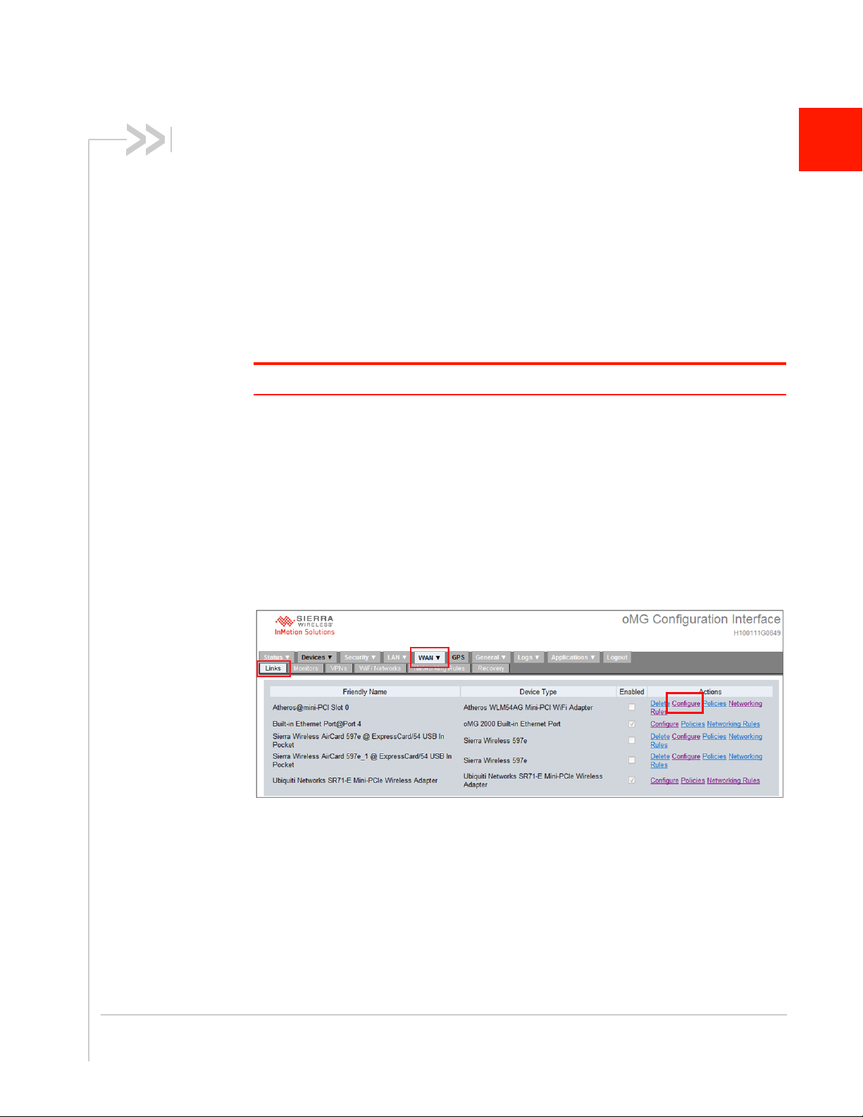
the WAN > Links tab.
To configure how these links provide WAN access:
1. Navigate to the WAN > Links tab.
2. Click Configure in the Actions column for a link:
5
Figure 5-1: WAN Link Tab
The following subsections provide an overview of the configuration for the most
common WAN links.
Rev 4 May.17 14
Page 15
Setting up the WAN
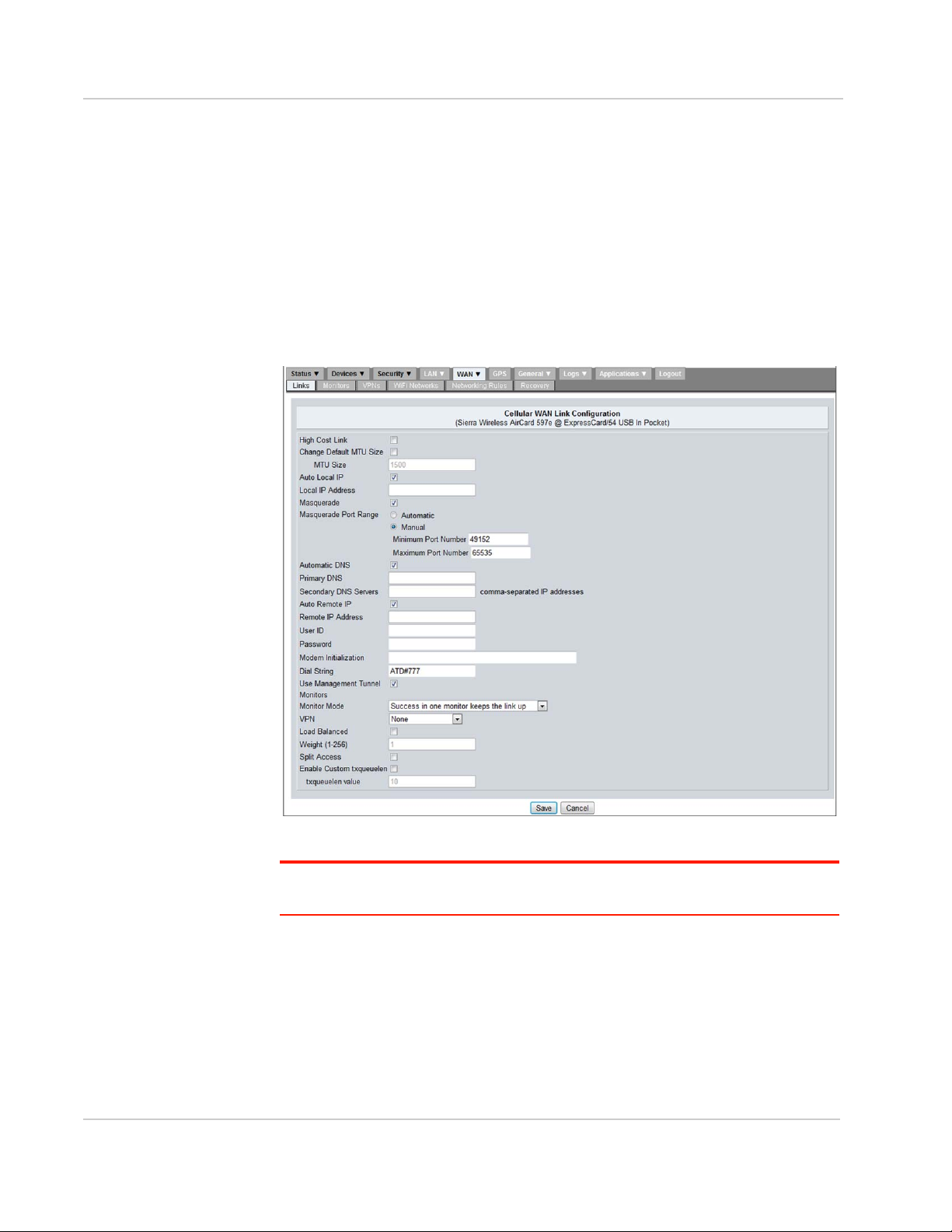
5.1.1 Cellular WAN Link Configuration
Cellular WAN is the most common type of WAN connection used on the oMG
because it provides connectivity from wherever cellular reception is available. This
type of link requires that a cellular card be installed in the oMG with a preauthorized cellular data plan from your Mobile Network Operator.
Configuration settings are specific to each type of cellular card installed, however
typical settings can include a dial string, user ID/password, and modem
initialization.
The screenshot below shows the cellular configuration settings for a Sierra
Wireless Aircard:
Figure 5-2: Common Cellular WAN Link Configuration Settings
Tip: Always test the cell card in a laptop with the APN before using it in the oMG, to
ensure the card has been properly configured.
Additional information on common cellular settings is available in Cellular WAN
Link Configuration Settings on page 68. For more information on specific settings
for your card contact your Mobile Network Operator or Sierra Wireless Technical
Support (see Contact Information on page 3).
Rev 4 May.17 15
Page 16
Operation and Configuration Guide 3.14
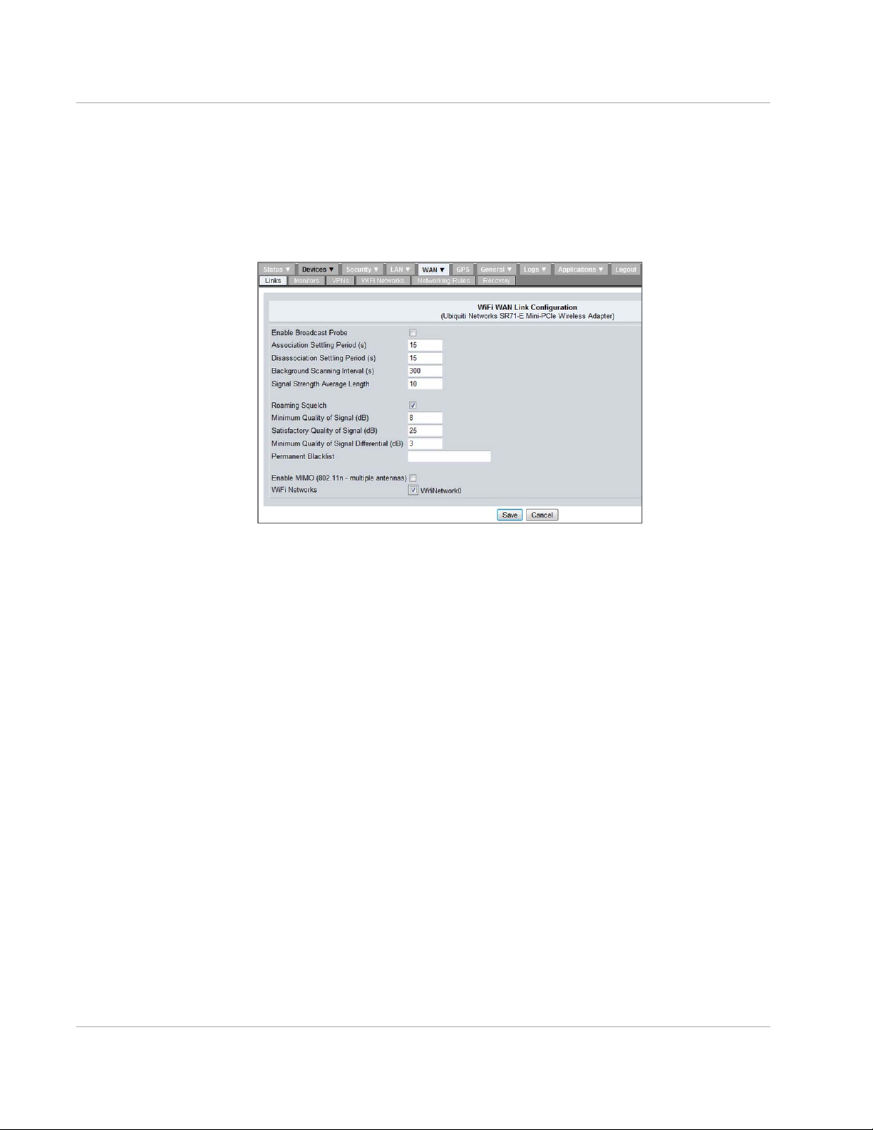
5.1.2 WiFi WAN Link Configuration
A WiFi link provides WAN access to the oMG via a WiFi AP which is often
available in locations such as vehicle depots. Since it's usually preferable to utilize
an AP when available, WiFi links are usually configured as the primary WAN
access method on the oMG.
The following screenshot shows the settings for a WiFi WAN link configuration:
Figure 5-3: WiFi WAN Link Configuration
Additional details on these settings are available in WiFi Link Configuration
Settings on page 71.
Once a WiFi WAN link has been configured it must then be assigned to an AP
profile which stores credential and other information required to communicate
with an AP. The creation of an AP profile and its assignment to a WiFi link is
described in Defining an Access Point Profile for WiFi Links on page 18.
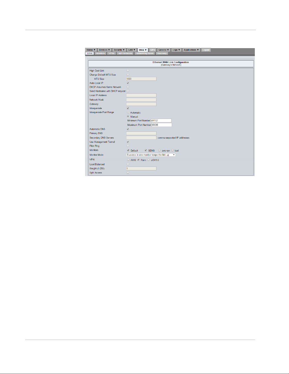
5.1.3 Ethernet WAN Link Configuration
An Ethernet (wired) connection can also be used to provide WAN access to the
oMG, though this is less common since the main purpose of the oMG is to
provide mobile WAN access using wireless methods.
16 4118618
Page 17
Setting up the WAN
The following screenshot shows the settings for an Ethernet WAN link:
Figure 5-4: Ethernet WAN Configuration Settings
For information about Ethernet WAN configuration settings see Ethernet Link
Configuration Settings on page 72.
5.1.4 Serial WAN Link Configuration
A serial modem can be connected to the serial port and will have a Device Type
of TTY Serial Port on the Serial Modem device listing screen.
Rev 4 May.17 17
Page 18
Operation and Configuration Guide 3.14
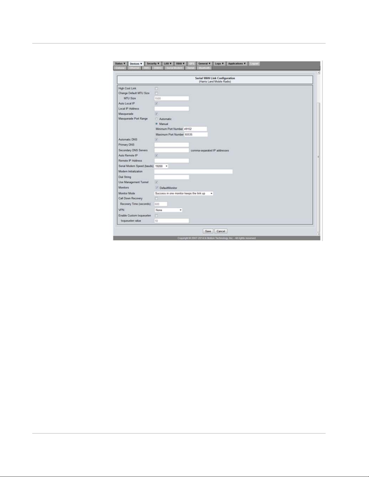
The following screenshot shows the settings for a serial modem WAN link:
Figure 5-5: Serial WAN Link Configuration
For more information see TTY Serial Port Link Configuration Settings on page 74.
5.2 Defining an Access Point Profile for
WiFi Links
An AP profile must be created for each WiFi AP that an oMG will use to access
the WAN. A profile creates an association between the actual AP and the
credentials (i.e. access, security, etc) required to connect to that AP from the
oMG. The settings for a profile must therefore match those defined at the actual
WiFi AP itself.
To define an AP profile:
1. Navigate to WAN > WiFi Networks, click Add New WiFi Network. The WiFi
Network Configuration page will be shown.
2. Configure the AP profile settings based on how they are configured in the
actual AP itself. Information about these settings can be found in WiFi
Networks Configuration on page 76.
3. Click Save to save the AP profile settings.
4. Set the WiFi link to use the WiFi AP profile:
a. Locate the WiFi link under WAN > Links.
18 4118618
Page 19
Setting up the WAN
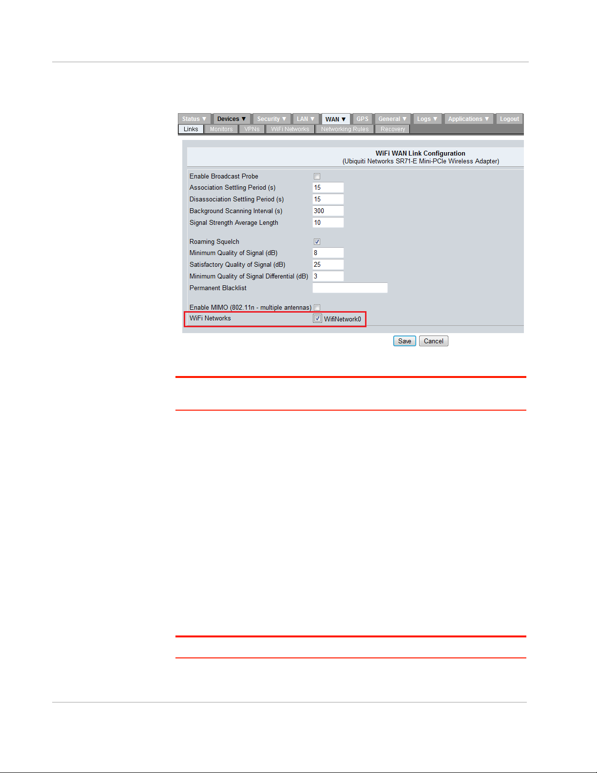
b. Click Configure, select the AP profile from the list next to WiFi Networks,
and click Save:
Figure 5-6: Selecting a WiFi AP profile for a WiFi WAN Link
Note: If multiple WiFi access points have been defined, each access point will be listed
and available for selection in the WiFi link's configuration settings.
5.3 Maintaining Communications with
Services of a WAN
The oMG can use a monitor to detect and try to recover from "high level"
communication failures occurring on a healthy connection between a WAN link
and a LAN segment (e.g. server timeouts due to a server being rebooted). A
monitor accomplishes detection and recovery by periodically checking against its
preconfigured parameters for problems such as a minimum number of connection
failures, timeouts, etc.
Using a monitor helps to ensure that communication sessions between devices
connected to the oMG's LAN, and services or hosts being accessed over the
WAN, are maintained and reestablished if possible.
It's highly recommended that a monitor be created and configured for cellular
devices.
Note: Currently, the only supported monitoring method is ICMP ping monitoring.
Rev 4 May.17 19
Page 20

Operation and Configuration Guide 3.14
Note: A monitor cannot be used for detecting "low level" communication problems such as
the loss of WAN connectivity (e.g. loss of cellular reception). These types of problems must
be dealt with using the oMG's WAN recovery feature as described in Recovering from
Dead WAN Connections on page 31.
To create or modify a monitor:
1. Navigate to WAN > Monitors.
2. Click the Add New WAN Monitor button to create a new monitor, or click on
Configure in the Actions column to modify an existing monitor.
3. Modify the monitor settings as required to detect a dead connection, ensuring
that the correct LAN segment is selected for the Source Address field. See
WAN Monitor Settings on page 76 for information on specific settings.
4. Click Save to save the monitor configuration.
5. Enable the monitor for a link:
a. If configuring a cellular or Ethernet link, enable the monitor on the link as
follows:
i. Navigate to WAN > Links, select the link to assign a monitor to and
click Configure.
ii. Locate and enable the Monitor in the link's Monitors settings.
iii. Click Save to save the link configuration.
b. If configuring a WiFi Link, enable the monitor in the AP profile assigned to
the link:
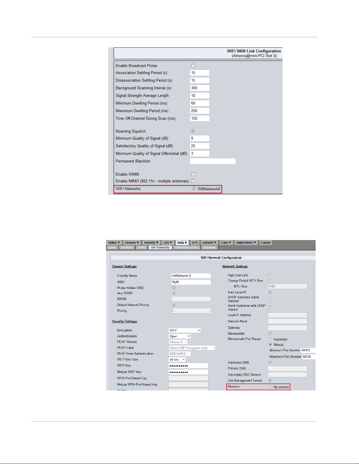
i. (Optional) Identify the AP profile assigned to the WiFi link if not
already identified, from under the WiFi Networks option in the link's
configuration settings:
20 4118618
Page 21
Setting up the WAN
Figure 5-7: Identifying the assigned access point profile
ii. Navigate to WAN > WiFi Networks , locate the AP and click
Configure.
iii. Select the monitor under network settings:
Figure 5-8: Assigning the Monitor to the WiFi Access Point Profile
iv. Click Save to save the AP profile settings.
Rev 4 May.17 21
Page 22

Operation and Configuration Guide 3.14
To delete a monitor:
1. Navigate to WAN > Monitors.
2. Locate the desired monitor to delete and click Delete in the Actions column.
3. Click OK when prompted to confirm the deletion.
5.4 Setting up a Link Policy
After configuring WAN link(s), it's recommended that one or more policies be
defined for each link.
Policies are one of the more powerful features of the oMG because they provide a
variety of ways to maintain network connectivity across a range of external
conditions.
The oMG includes a rich set of configurable policies, which define how and when
the various WAN devices installed in the unit should provide connectivity. These
policies can help maintain connections as signal strengths fluctuate, and can help
to maintain the most optimal and cost efficient connectivity.
This section describes how the various policies work and how to tune them for
optimal connectivity and performance. Since policies can be set up to work in
concert with other policies across links, this section includes a discussion and
examples on how to set up multi-policy configurations.
Policies determine which link should be used based on some sort of criteria such
as stability. Selection is based on a scoring system where penalties for issues
(e.g. a link being down) reduce a link's score. Each link is evaluated based on its
score and the link with the highest score is set to the active link. Policies can be
combined to form an arithmetic score that affects active link determination.
The general goals for implementing policies are as follows:
• Reduce or eliminate loss of connectivity and associated downtime
• Reduce or eliminate issues associated with the loss and re establishment of a
connection such as having to rebuild a VPN connection
• Maintain a stable connection
• Maintain the fastest throughput available
• Reduce cellular usage costs
• Use "low cost" links including WIFI
To achieve these goals and make the most of these policies, oMGs are usually
equipped with multiple WAN devices which include both WiFi and multiple cellular
devices. This allows for the managed switching between these devices as defined
by the policies.
Policies work on a system of scores which can be decremented (penalized) when
some condition is exceeded (e.g. a connection is lost), and gradually incremented
again once the condition has been met (e.g. a connection is eventually
re-established).
These parameters allow for the dynamic selection of links based on a variety of
factors and multiple policies can be combined to select a link amid a wide range
of external and environmental factors.
22 4118618
Page 23

Setting up the WAN
To define a policy for a link:
1. Navigate to WAN > Links and click on Policies in the Actions column.
2. Locate the desired policy in the list and click Configure in the Actions
column.
3. Set Enable this policy to checked and proceed to configure the policy
settings. See Policies on page 64 for detailed information about the policy
settings.
4. Click Save when the configuration is complete. Back on the policy listing
screen, verify that the Enabled field is checked for the policy.
5. Repeat the steps above for any additional policies that should be configured.
Note: Policy configurations are not global across all links, and must configured on a per
link basis as required.
5.4.1 Special Considerations for WiFi Links
When planning how policies will be used to select/deselect WiFi links, be sure to
take the Association Settling Period and Disassociation Settling Period of WiFi
links into account (see WiFi Link Configuration Settings on page 71 for a
description of these settings). These settings prevent the accidental selection and
de selection of a WiFi link which could occur when brief WiFi connectivity is
available (e.g. when driving past a depot's WiFi hostspot).
Note: These settings are not available on cellular devices.
By default, both are set to 15 seconds, and will prevent a WiFi link's status from
changing from "down" to "up" and or "up" to "down" respectively. This makes the
link unavailable for selection by a policy during that 15 second time frame.
As a result, penalties and recovery periods of policies on WiFi links can generally
be set to 0, since the two settling periods already handle most situations where
brief WiFi connectivity is to be ignored.
5.4.2 Dynamic Priority Policy Overview
The Dynamic Priority Policy is used to provide a managed switch between WAN
links for when the current link in use goes down. This policy is typically applied
when multiple WAN devices have been installed in an oMG so that backup
connections are available.
A key aspect of the Dynamic Priority Policy is its inherent ability to handle the "flip
flopping" of connection states, where by the link may repeatedly come back online
again but then return to its disconnected state. In other words, it is intended to
hold off switching back to a particular link until it has proven itself stable/
trustworthy.
The Dynamic Priority Policy avoids such flip flopping between links that might
occur, by effectively waiting for the unstable device to regain an acceptable level
of stability before switching back to it.
Rev 4 May.17 23
Page 24

Operation and Configuration Guide 3.14
There are actually two sets of settings on the Dynamic Priority Policy
configuration screen:
Figure 5-9: Settings on the Dynamic Priority Screen
The first set allows for the enabling and setting of a Priority Score on a link. The
priority score is added to a base score of 1000 which is assigned by the system.
This combined score then indicates the priority (preference) of the link which the
system determines by comparing against the scores from other links. Note that
equal values can be specified when enabling the policy on different links to
indicate that those links are equally preferable.
It's important to note that although this setting appears on the configuration
screen of the Dynamic Priority Policy, it's actually not specific to that policy and
can be set and used in conjunction with any policy.
The second category of settings are for the Dynamic Priority policy itself and
include the ability to enable and specify a Link Down Penalty value which can
reduce a link's score when some condition is not being met (e.g. a link has not
been able to establish a connection for some time). The other value that can be
defined is the Recovery Period which specifies the amount of time that a link's
score will be incremented again by the system. A link "proves" itself when its
score increments back to its original combined score over this period, at which
point the system may reselect it as the active link.
Consider the following example where there is a WiFi device and two cellular
devices (C1 and C2) installed on an oMG. The WiFi device is the most preferred
device while C1 is preferred over C2. To model this in the Dynamic Priority policy
the following settings were used:
Table 5-1: Example of Dynamic Priority Settings
WiFi C1 C2
Base Score 1000 1000 1000
Priority Score 300 200 100
Link Down Penalty Not Enabled 300 300
Recover Period Not Enabled 120 120
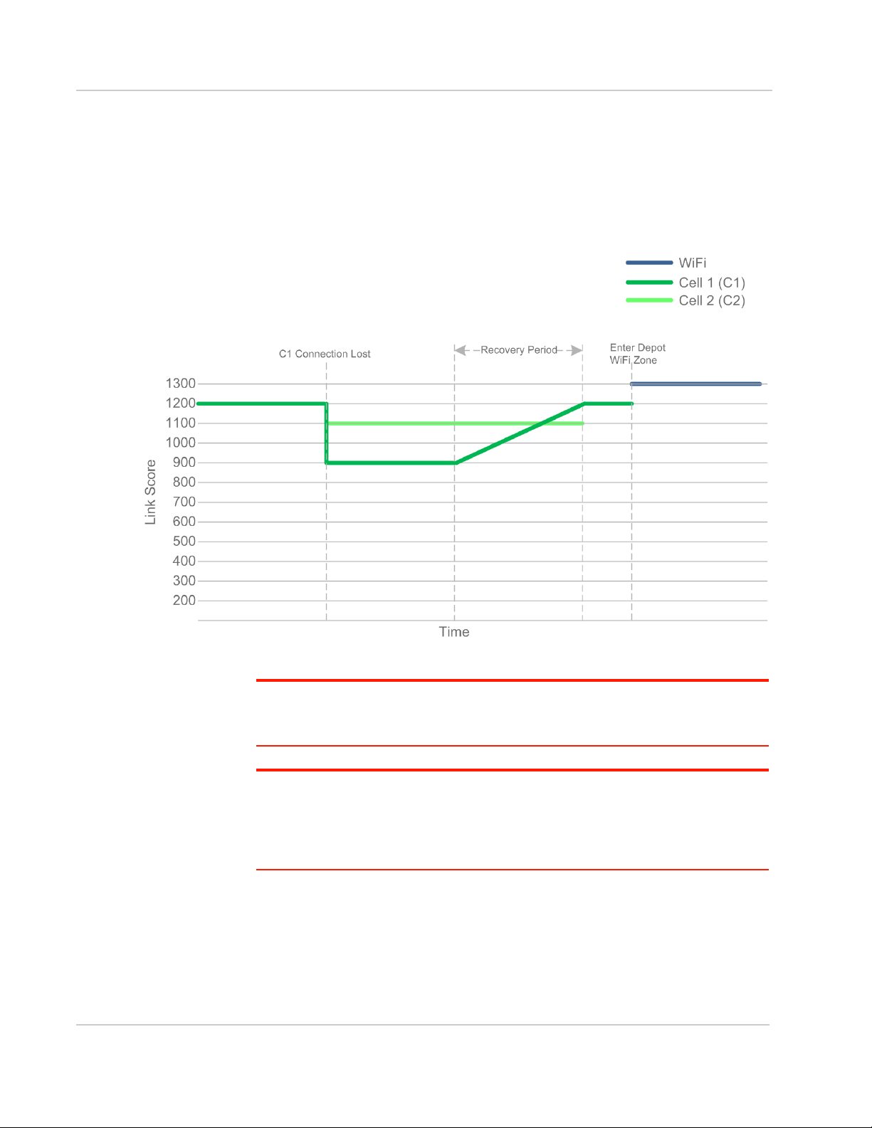
The graph in Figure 5-10 on page 25 shows a simple time line in which a vehicle
is outside of a depot, C1 is the current WAN link, but the connection is eventually
lost. As a result C1's overall score is re calculated using its current score minus its
assigned penalty (1200-300) to give a new score of 900. Since this is lower than
C2's current score of 1100, C2 takes over.
24 4118618
Page 25
Setting up the WAN
When C1's connection is re-established, its recovery period of 120 seconds
begins, during which C2 remains as the current WAN link, and C1's score
gradually increases. When C1's score finally becomes greater than C2 again, C1
is restored as the active link, even if its recovery period has not yet completed.
The graph also shows that a short time later, the vehicle enters the WiFi zone of a
depot, at which point the WiFi link, which is the most preferred link, becomes the
active link.
Figure 5-10: Basic example with WiFi and two Cellular links
Note: This graph is intended to provide a basic introduction to how policies use scoring to
switch between links. In practice, other factors such as a WiFi device's Association Settling
Period mean that switches won't happen instantaneously.
Tip: A priority score of 100 with a penalty of 300 and a 120 second recovery time, make
for good, "granular" numbers to use because they make it easy to monitor switchovers
(e.g. via logging) when using the Dynamic Priority policy. In particular a 120 second
recovery time will allow for a ping monitor to occur every 30 seconds so that three pings
occur during the recovery period.
See Dynamic Priority Policy on page 64 for a summary of this policy's settings.
Rev 4 May.17 25
Page 26

Operation and Configuration Guide 3.14
5.4.3 Geographical Regions Policy Overview
The Geographic Region Policy increments a link's score to make it the preferable
WAN link for a defined geographic bounding region. Up to three regions can be
defined per link. This policy is often used when the quality and/or cost of coverage
for a particular area is known ahead of time and selection of the best WAN link
can be decided in advance (i.e. when configuring the WAN link).
For example, if the cellular coverage for different Mobile Network Operators is
known to be good in certain areas, then regions for those areas can be defined on
the respective links and scores applied accordingly.
Similarly, if there is a WiFi connection available (e.g. within and around a depot),
then a region for the depot could be defined for the WiFi WAN link with a very high
score to ensure that the WiFi WAN link is used when the vehicle is in or near the
yard.
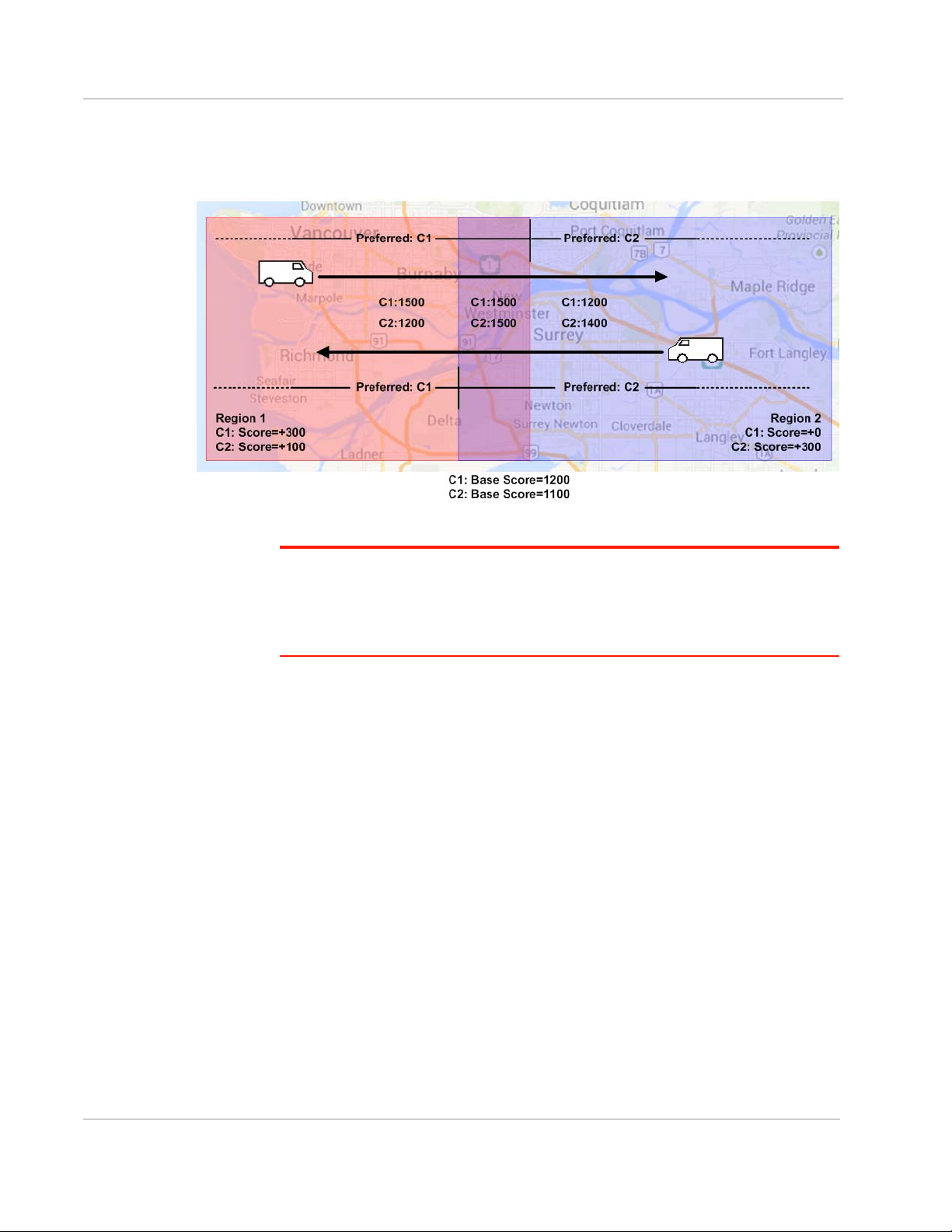
As a basic example, consider the following in which there are two regions, where
part of each overlaps the other. The coverage in Region 1 is known to best for
Mobile Network Operator 1 (C1), and the coverage in Region 2 is known to be
best for Mobile Network Operator 2 (C2).
To provide the best coverage and prevent unnecessary switchovers throughout
the vehicle's journey, the following policy settings were defined for two cellular
WAN links and the following settings were specified:
Table 5-2: Example of Geographical Region Policy Settings
Dynamic Priority
Policy
Cellular Link 1 (C1) Priority (Base) Score:
1200
Cellular Link 2 (C2) Priority (Base) Score:
1100
Geographic Region
Policy
Region 1 Score: 300
Region 2 Score: 0
Region 1 Score: 100
Region 2 Score: 300
The overall score for a cellular link is then calculated as follows:
Overall score = Priority Score + Score for current region
For example, when a vehicle is in Region 1, C1's score is 1200+300=1500 and
C2's score is 1100+100=1200.
In the case of overlapping regions, each link's score is calculated by including the
link's score for all regions which are part of the overlap.
For example, when a vehicle is in an overlapping region comprised of Region 1
and Region 2, C1's score is 1200+300+0=1500 and C2's score is
1100+100+300=1500.
26 4118618
Page 27
Setting up the WAN
Note that the scores match in the overlapping region, so a switch between cellular
links will not occur when entering the overlapping zone in order to prevent an
unnecessary switch as illustrated in Figure 5-11:
Figure 5-11: Geographic Region Example with overlapp ing Regio ns
Tip: Configuring the bounding boxes for each region requires knowledge about the
latitude and longitude coordinates for the upper and lower points which make up each
region, since the oMG's LCI does not provide a mapping interface to visually define zones.
Therefore, configuring this policy will require you to determine the coordinates to be
entered in the policy.
See Geographic Region Policy on page 64 for a summary of this policy's settings.
5.4.4 Time Period Policy Overview
The Time Period Policy promotes one link over others when operating within a
defined time period. Up to three time periods can be defined per link. This can be
used to make use of reduced data costs or to compensate for bandwidth
saturation periods.
For example, when a link's throughput is known to drop during a particular time of
day (e.g. due to network congestion), a time period could be defined on a backup
link for this known period with a fairly high score applied, so that the backup link is
temporarily selected and used to maintain acceptable throughput.
Another use case includes switching to the link of a Mobile Network Operator who
provides cheaper cellular coverage during evenings.
See Time Period Policy on page 64 for a summary of this policy's settings.
Rev 4 May.17 27
Page 28
Operation and Configuration Guide 3.14
5.4.5 Velocity Policy Overview
The Velocity Policy penalizes one link so that others become preferable based on
velocity. It accomplishes this by applying a penalty on a WAN link when the oMG
detects that the vehicle is exceeding a specified speed threshold. This is done to
proactively switch off a link in a managed way prior to the link actually failing,
which would require both the connection and VPN to be re-established.
Since this policy applies a penalty when the defined speed threshold has been
met and continues to penalize the link's score while the threshold is being
exceeded, this policy is typically applied to a WiFi link to facilitate a managed
hand off from that link to a cellular link, such as when leaving a depot.
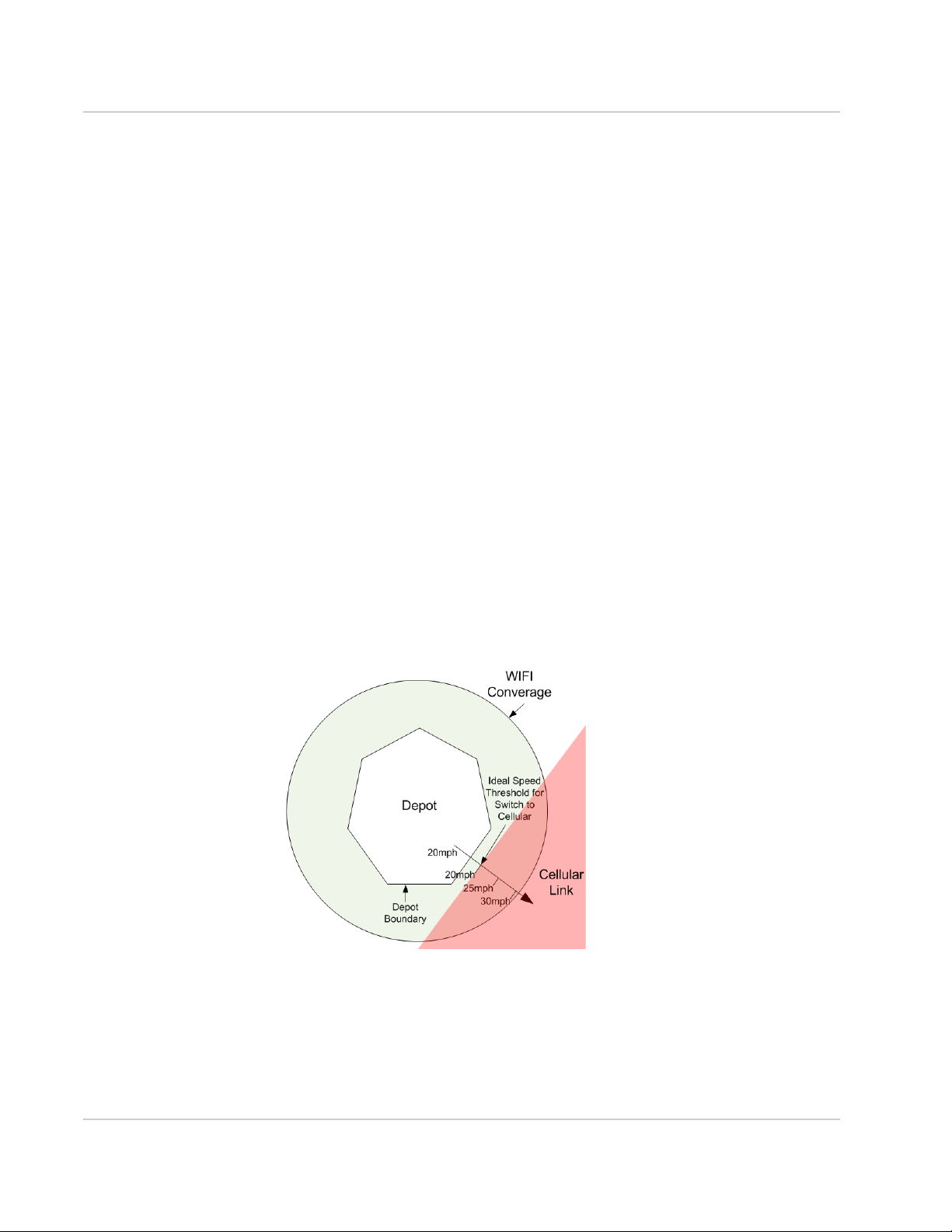
For example, when applied to a WiFi link, the policy could define a speed
threshold of 20mph so that the vehicle can travel around a depot, utilizing that
link. However, once the vehicle leaves the depot and the speed threshold is met,
the link becomes penalized and another link (e.g. cellular) becomes active.
A key aspect in tuning this policy is to define an appropriate speed threshold such
that the switch from WiFi to cellular happens before WiFi connectively is lost. This
will provide a seamless switch without a drop in connection and will prevent
issues such as having to rebuild a VPN connection which normally occur when a
connection is lost.
In the example of a vehicle leaving a depot, there would likely be a small area of
WiFi coverage outside of the depot, and the vehicle would also likely increase its
speed as it exits the region and travels through this zone. Therefore an
appropriate speed threshold should be chosen to ensure that a switch to cellular
occurs before WiFi connectively is completely lost, thus preventing any drop in
connection during the transition from WiFi to cellular as illustrated here:
Figure 5-12: Setting a Speed Threshold to Switch to Cellular before WiFi Coverage is lost
Note that GPS "jitter" can occur when a vehicle is parked in a location which can
cause the speed threshold(s) defined in the Velocity Policy to be satisfied, thus
resulting in an inadvertent switch in links. It's therefore recommended that a GPS
repeater be installed near the depot to reduce such jitter.
See Velocity Policy on page 65 for a summary of this policy's settings.
28 4118618
Page 29

Setting up the WAN
5.4.6 Signal Strength Policy Overview
The Signal Strength Policy is typically used for the selection of WiFi and cellular
connections based on signal strengths (e.g. when located in an area with good
cellular coverage). In other words, it penalizes a link so that other links become
preferable and thus proactively selected based on signal strengths. This requires
that multiple wireless devices have been installed, often with one link identified as
the preferred link and the other(s) as the backup link(s).
Note: For cellular devices, this policy is only available for "Direct IP" cell cards and not for
older "PPP style" cards. This is because the signal strength of the latter cannot be determined while the call is up.
The policy applies a penalty to a link when its signal strength falls below a
specified threshold to decrease its score. The link's penalty is removed when the
signal strength returns and the recovery period is successfully met. This helps to
ensure that signal strengths stabilize before switching back to preferred links.
If one link has been configured as the preferred link (e.g. due to lower data plan
costs), then the Signal Strength Policy should be configured on each link such
that lower quality signal strengths are acceptable on that preferred link. This will
help to ensure that the preferred link is utilized the most as signal strengths
between devices fluctuate.
If devices from different Mobile Network Operators are equally preferable, the
signal strength in the policy for each device's link should be set the same. This
will prevent an unnecessary switchover from occurring since both devices have
been designated as equally capable.
Note that since a weak signal can still provide good throughput and a good signal
may not always provide good throughput (e.g. due to the variance of the Internet),
the Signal Strength policy is typically used to drop a bad connection that doesn't
necessarily cause a ping monitor failure. A typical threshold for switching to
another link is when the signal strength drops to -85 dBm. Dropping the
connection at higher levels may unnecessarily deprive the oMG from good
performance or result in the switch over to a lower performing link.
See Signal Strength Policy on page 65 for a summary of this policy's settings.
5.4.7 Use Cases
5.4.7.1 Dynamic Priority Policy and Velocity Policy
Combination
The following example shows how to combine the Dynamic Priority Policy with the
Velocity Policy to choose between links.
In this example, an oMG is equipped with a WiFi and a cellular link. The Dynamic
Priority Policy has been applied to both links with a default score of 1200 for the
WiFi link, and 1000 for cellular. The goal here is to choose WiFi as the preferred
link whenever possible since its performance, cost of use, and connection quality
Rev 4 May.17 29
Page 30
Operation and Configuration Guide 3.14
should be superior to that of the cellular link, when WiFi is available. The WiFi link
has been assigned a penalty of 600 which will cause its score to fall below that of
the cellular link when the WiFi connection is lost.
The Velocity Policy has also been applied to the WiFi link with a speed threshold
of 25mph and a penalty of 600. This ensures that the WiFi link's score falls below
that of the cellular link when the vehicle's speed becomes too high.
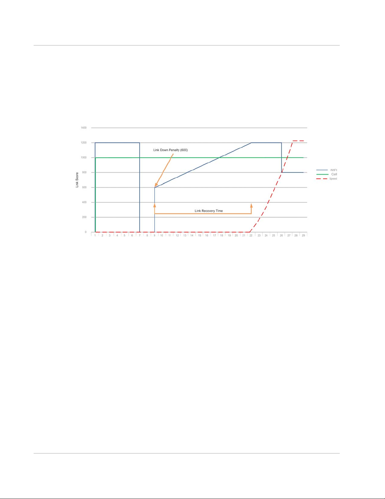
Figure 5-13 provides a timeline showing how an oMG uses this configuration to
choose between a WiFi link and a cellular link:
Figure 5-13: Dynamic Priority and Velocity Policy Combination
The following can be observed on this timeline:
• WiFi starts with a higher score of 1200; cellular with 1000. The vehicle is
stationary with no speed.
• At 6 minutes, the WiFi connection is lost and the cellular connection takes
over because the Dynamic Priority Policy drops the WiFi link's score below
that of the cellular link's.
• At 9 minutes, the WiFi link recovers and a link down penalty of 600 is applied.
• The WiFi connection's score continues to increase over its link recovery
period.
• At 18 minutes, the WiFi's score exceeds that of the cellular link and it
becomes the active link.
• At around the same time the vehicle starts to accelerate.
• At 26 minutes, the vehicle’s speed exceeds the speed threshold defined in
the Velocity Policy on the WiFi link. This reduces the score of that link by 600
causing the cellular link to take over.
30 4118618
Page 31

Setting up the WAN
5.5 Setting up Firewall Rules
5.5.1 Configuring the WAN Rule Firewall
Settings
WAN firewall settings are configured through the creation of WAN networking
rules under the WAN > Networking Rules tab.
The oMG's WAN firewall can deny/allow access to both incoming and outgoing
traffic based on a source/destination IP address combination and on TCP, UDP, or
both protocols. The firewall also allows for port forwarding so that services within
the oMG's LAN may be accessible over the WAN.
To define firewall rules on the oMG:
1. Navigate to WAN > Networking Rules.
2. Select Accessing Blocking, Accessing Granting, or Portforwarding in the rule
dropdown and click Add New Networking Rule.
3. Enter a descriptive name for the rule.
4. Set the desired traffic direction in the Direction field to allow/deny access or to
port forward on.
5. Configure the remaining fields and click Save. See Networking Rules on
page 65 for more information about the specific configuration fields for each
rule type.
Note: Both Access Blocking and Access Granting rules may be created to implement very
specific access policies. Multiple rules of each type may also be created.
5.5.2 Deleting WAN Rules
To delete a WAN network rule:
1. Navigate to WAN > Networking Rules.
2. Locate the desired networking rule to delete and click Delete in the Actions
column.
3. Confirm the deletion when prompted by clicking OK.
5.5.3 Recovering from Dead WAN Connections
The oMG can be configured to reboot the entire unit after WAN connectivity has
been down for a certain amount of time. This type of recovery is used when a "low
level" communications problem has occurred such as the loss of cellular
coverage. In such a case the "high level" monitoring provided by a WAN Monitor
(described in Maintaining Communications with Services of a WAN on page 19)
will not be sufficient since monitors deal with problems like trying to access a
remote server that has gone down. Therefore it's important that WAN recovery be
enabled as described below.
Rev 4 May.17 31
Page 32

Operation and Configuration Guide 3.14
To enable WAN recovery:
1. Navigate to WAN > Recovery.
2. Set the WAN Link Recovery field to enabled.
3. Configure each of the recovery settings as required. See WAN Recovery
Settings on page 85 for detailed information on these settings.
Enabling WAN Link Recovery will restart the entire unit and force the oMG to
boot up again if WAN connectivity is lost.
The Remote Configuration WAN Recovery and Restore previous configura-
tion after settings can be used to discard changes made remotely on an AMM
which have caused a loss of WAN connectivity.
4. Click Save to save and activate the recovery settings.
32 4118618
Page 33
6: Setting up the LAN
One of the main features of the oMG is its ability to provide a mobile LAN via both
wired (Ethernet) ports and wireless (WiFi).
Note: The oMG does not support USB-to-Ethernet adapters for LAN operation.
6.1 Configuring LAN Access
By default, an oMG is usually preconfigured to provide LAN access via multiple
Ethernet ports and through at least one unsecured WiFi AP. Therefore it's important to
assess and configure the type(s) of LAN access currently available on the unit before
the oMG is deployed, using the following steps. The careful and deliberate
configuration of LAN access will help to ensure a more secure system.
Note: To add or remove LAN devices see Preparing the Network Interfaces on page 13.
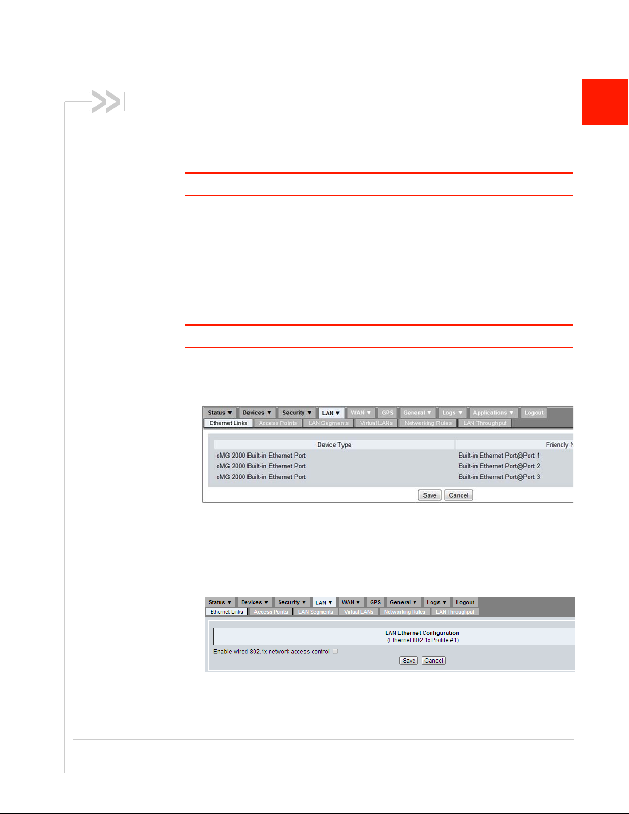
1. Determine which Ethernet ports are set to provide LAN access, by navigating to
LAN > Ethernet Links. The following status screen will display all Ethernet ports
through which the LAN can be accessed:
6
Figure 6-1: Listing of Ethernet Links
2. (Optional) Enable 802.1x network access control for Ethernet:
a. Click on Configure beside the desired Ethernet port to configure.
b. Enable the Enable wired 802.1x network access control option to display the
configuration fields:
Figure 6-2: Enabling 802.1x for an Ethernet Link
Rev 4 May.17 33
Page 34

Operation and Configuration Guide 3.14
c. Configure the 802.1x settings and click Save to save the changes. For
information on each setting see LAN Ethernet 802.1x Settings on
page 84.
3. Configure the LAN APs: navigate to LAN > Access Points and click on
Configure under the Actions column for each access point listed:
Figure 6-3: Defining a LAN WiFi Access Point
Modify the AP settings if required and click Save. See Access Point Settings on
page 80 for detailed information about each setting.
6.2 Configuring LAN Segments
By default, the oMG comes preconfigured with one LAN segment called Default
LAN on which all factory enabled LAN links operate. Ethernet links can only be
assigned to one segment while a WiFi link can be used across multiple segments
when configured with additional BSSIDs (maximum of three).
LAN segmentation and the process of adding LAN segments, is used for
advanced networking scenarios when LAN traffic from different devices must not
be partitioned (e.g. when public internet access is made available for WiFi users
while private onboard equipment hooked up to the oMG's Ethernet ports must not
be accessible by WiFi users). The creation of multiple LAN segments can also be
useful for specifying different network policies or routing rules on each segment.
Before deploying an oMG, it's important to review how the LAN segment(s) are
configured on the unit to ensure that network traffic visibility remains as secure as
possible.
To add or configure LAN segments:
1. Navigate to LAN > LAN Segments.
2. To add a new LAN segment, click the Add New LAN Segment button. To
modify an existing LAN segment, locate the subnet to be configured and click
Configure in the Actions column.
Figure 6-4: Configuring or adding a segment
34 4118618
Page 35

Setting up the LAN
3. Configure the segment's settings and click Save. See LAN Segment Settings
on page 83 for information on each specific setting.
Figure 6-5: LAN segment configuration screen
Note that each LAN segment must have a different scope (i.e. IP address range)
from the other segments. A warning will be provided if an attempt is made to
cross segment scopes as shown in Figure 6-6:
Figure 6-6: Warning for a segment configuration address range which overlaps another
To assign a device to a different LAN segment:
1. Navigate to LAN > LAN Segments.
2. Locate the device to assign and select the LAN segment from the dropdown
in the Actions column.
Rev 4 May.17 35
Page 36

Operation and Configuration Guide 3.14
3. Click the Apply Changes button. After a brief period, the screen will refresh
and the device listing will move down to the new LAN segment.
To delete a LAN segment:
1. Navigate to LAN > LAN Segments.
2. Locate the segment to delete and click Delete in the Actions column.
3. Click OK when prompted to confirm the deletion.
After a segment has been deleted, the interface(s) that were assigned to that
segment will be reassigned to the “Default” segment.
6.3 Configuring DHCP and Static IP
Addresses
Each LAN segment can be configured to assign IP addresses to LAN devices
using DHCP or can utilize statically assigned IP addresses.
By default a LAN segment is set to use DHCP with an address range of
172.22.0.100 to 172.22.0.200. The default gateway address for the default LAN
segment is 172.22.0.1.
1. Navigate to LAN > LAN Segments.
2. Locate the LAN segment to modify, and click Configure in the Actions column.
See LAN Segment Settings on page 83 for details on each setting.
3. To enable DHCP, set the Enable DHCP Server field to enabled and assign the
DHCP address range and lease time in the DHCP Low Address, DHCP High
Address, and DHCP Client Lease Time fields.
4. To use static IP addresses, set the Enable DHCP Server to disabled. Also
ensure that each device on that segment has been configured with a static IP
address via the configuration settings available on each device.
5. Click the Save button.
6.4 Setting up the LAN Firewall
6.4.1 Configuring the LAN Rule Firewall
Settings
LAN firewall settings are configured through the creation of LAN networking rules
under the LAN > Networking Rules tab.
The oMG's LAN firewall can deny/allow access to both incoming and outgoing
traffic based on a source/destination IP address combination, and on TCP, UDP,
or both protocols.
To define firewall rules on the oMG:
1. Navigate to LAN > Networking Rules.
2. Select Accessing Blocking or Accessing Granting in the rule dropdown and
click Add New Networking Rule.
36 4118618
Page 37

Setting up the LAN
3. Enter a descriptive name for the rule in the Rule Name field.
4. Set the desired traffic direction in the Direction field to allow or deny access
on.
5. Configure the remaining fields and click Save. See Networking Rules on
page 65 for more information about the specific configuration fields for each
rule type.
Note: Both Accessing Blocking and Access Granting rules may be created to implement
very specific access policies. Multiple rules of each type may also be created.
6.4.2 Deleting a LAN Network Rules:
1. Navigate to LAN > Networking Rules.
2. Locate the desired networking rule to delete and click Delete in the Actions
column.
3. Confirm the deletion when prompted by clicking OK.
6.5 Attaching a Network Printer
The oMG can support a network printer via an Ethernet port for use on its LAN.
Use the following steps to configure a network printer:
1. Identify the Ethernet port number that the printer is attached to.
2. Navigate to LAN > LAN Segments and ensure that the Ethernet port is
assigned to the Default LAN Segment. Also set the Enable DHCP Server field
depending on if the printer will use a static IP address or will obtain one
through DHCP from the oMG and click Save. See Configuring LAN Segments
on page 34 for information on configuring and assigning LAN segments.
3. Configure the printer to use either a static IP address or to obtain an IP
address from the oMG using DHCP. Refer to your printer manual for more
information.
Note: If a static IP address is used, it must be within the subnet range defined by the IP
address and network mask in the Default LAN segment configuration. To avoid collisions
with DHCP clients, the static address should also be outside the specified DHCP address
range.
4. Attach the network printer to the oMG and print the network status page to
verify that an IP address is correctly assigned. If the printer is using DHCP
and an IP address is not shown, verify that there is a connection light on the
printer indicating LAN activity, and that the printer is properly configured to
use DHCP. Refer to your printer manual for more information.
5. Attach a PC to the oMG through either a WiFi connection or through an
Ethernet port. From a command prompt on the PC, verify that a ping to the
printer IP address is successful. If the ping is successful, use the PC's printer
utility software to add a local printer using a standard TCP/IP port. Use the
Rev 4 May.17 37
Page 38

Operation and Configuration Guide 3.14
printer’s IP address (as determined above) when asked for the Printer Name
or IP Address.
6.6 Setting up Virtual LANs
A VLAN can be used when devices inside the vehicle require VLAN tagging for
their operation, or the vehicle LAN has a switch with VLAN tagging enabled. If a
vehicle has VLANs configured, or four Ethernet ports are not enough, they can be
multiplied by using a switch and VLAN tagging.
For information on VLAN configuration settings see VLAN Settings on page 84.
38 4118618
Page 39

7: How to Configure a VPN
The oMG can be configured to provide access to one or more Virtual Private
Networks (VPNs). A VPN allows LAN devices connected the oMG to access an
enterprise network and vice versa.
The oMG supports the following VPNs and VPN related technologies:
• IPSec VPNs: LAN to LAN (most common) and Host to LAN. For documentation
on configuring IPSec VPNs, see source.sierrawireless.com.
• Certificates and pre-shared keys.
VPN configuration on the oMG consists of creating a VPN profile with settings that
match those of a VPN server. Before configuring a VPN on the oMG it's important to
first gather some or all of the following information:
oMG
• LAN IP Subnetwork
• LAN Mask
• LAN IP Address
• Security components such as pre-shared key, certificates etc.
Note: Using pre-shared keys (PSK) for authentication on some VPN servers will require the
oMG to have a static IP on the WAN interface used for VPN.
7
VPN Server
• Server IP Address
• Destination Network IP Address
• Destination Network Mask
• Security components such as pre-shared key, server certificates etc.
To configure a VPN Profile:
1. Ensure one or more WAN links have been properly configured as described in
Section 5.1 - Basic WAN Link Configuration.
2. Ensure one or more LAN segments have been configured as described in 6.2 Configuring LAN Segments.
3. Navigate to WAN > VPNs to display the available VPNs and click Add New IPsec
VPN to access the VPN Configuration page.
Figure 7-1: VPN Listing Screen
Rev 4 May.17 39
Page 40

Operation and Configuration Guide 3.14
4. Configure the VPN fields in accordance with the settings on the VPN server
being used. See VPN Configuration Settings on page 85 for detailed infor-
mation on each setting.
5. Click Save to save the VPN.
Tip: When first testing a VPN, it's recommended that monitors be disabled initially in order
to test that all of the other configuration parameters are working properly.
Note: IPSec VPN has a maximum throughput of 40 Mbps due to the processing required
for encapsulation.
7.1 Detecting Dead VPN Connections
An oMG VPN profile can be configured to send packets to a VPN server in an
effort to detect dead connections. Doing so helps to protect resources by
attempting to reconnect to a VPN server.
When using IKEv1 for a VPN, Dead Peer Detection (DPD) can be enabled on the
VPN configuration screen which will detect when a VPN service is down.
For IKEv2, it is recommended that MOBIKE be enabled if multiple WAN links are
available which will automatically switch links when one goes down. MOBIKE has
been tested by Sierra Wireless against Sierra Wireless’ ACM VPN server. For
more information on compatibility with VPN servers contact Sierra Wireless
Technical Support (see Contact Information on page 3).
Important: When MOBIKE is enabled, DPD should be disabled on the gateway side
because it can interfere with the fast switching provided by MOBIKE.
For both IKEv1 and IKEv2, it is recommended that a monitor be configured as
follows to detect a dead connection to the VPN server and to attempt to reconnect
to it.
• The monitor's Host field must be set to a host which can only be reached
through the VPN.
• The Source Address field must be set to a LAN segment assigned to the
VPN.
• The monitor must then be assigned to the VPN profile by selecting it under
the Monitors field in the profile.
For information on creating a monitor see Maintaining Communications with
Services of a WAN on page 19.
40 4118618
Page 41

How to Configure a VPN
7.2 Multi-VPN Support
oMG 3.14 and above support the creation of multiple VPN tunnels per WAN link.
With this feature, one or more VPN policies can be applied to one or more WAN
links in the LCI:
Figure 7-2: Selecting Multiple WAN Links
The VPNs assigned to a WAN link can also be viewed by navigating to
Status > WAN, enabling Show Extended Status and locating information for the
WAN link:
Rev 4 May.17 41
Page 42

Operation and Configuration Guide 3.14
Figure 7-3: Viewing the VPNs assigned to a WAN Link
The multi-VPN feature has the following attributes and restrictions:
• Each WAN link / WiFi Network can have up to 10 VPNs.
• If a WAN link / WiFi Network has two or more VPNs, any of these VPNs
cannot be in HOST2LAN mode.
• If a WAN link / WiFi Network has two or more VPNs, any of these VPNs
cannot use IKEv1.
• If a WAN link / WiFi Network has two or more VPNs, any of these VPNs
cannot have both a local and remote subnet overlapping at the same time.
• Distinct ping monitors can be assigned to each VPN tunnel.
• The oMG’s LCI provides validation to ensure there is no address space
collision between VPNs applied to same WAN link.
• The oMG provides bandwidth control to ensure a single VPN doesn’t
consume all available bandwidth on a WAN link.
Note: When using multiple VPN tunnels configured for non-MOBIKE, VPNs may fail to
reconnect after a WAN link switch. Customers should only use MOBIKE when configuring
a multi-tunnel VPN.
42 4118618
Page 43

How to Configure a VPN
7.3 Configuring DNS Zones for Private
DNS Server Use
In deployments that make use of VPNs with internal DNS servers (to resolve
specific internal domains) and public DNS servers, the oMG must be configured
to use DNS zones.
To configure one or more oMGs for DNS zones:
1. In the LCI, set the Primary DNS and Secondary DNS Servers fields to the
addresses of the public DNS servers to be used. (Applies to the WAN > Links
configuration screens (Ethernet, Cellular) and WAN > Wi-Fi Networks configuration screen.)
2. On a computer, create a DNS zones file named “private-zone.conf”. In this
file, indicate the domains to be resolved by the indicated internal DNS
servers.
For example (filename: private-zone.conf):
zone "customer.local" IN {
type forward;
forward only;
forwarders { 10.5.1.1; 10.6.1.1; };
};
zone "customer.internal" IN {
type forward;
forward only;
forwarders { 10.5.1.1; 10.6.1.1; };
};
In this example, the domains “customer.local” and “customer.internal” are
both to be resolved by the internal DNS servers “10.5.1.1” or “10.6.1.1”. Any
other domains will be resolved by the public DNS servers specified in the
WAN Link’s Primary DNS and Secondary DNS Servers fields.
3. Use AMM to store the file on the oMG(s):
a. In AMM, select Config > Deploy > Upload to copy the file to the AMM.
b. Select Config > Deploy > Deploy to store the file on selected oMGs.
Note: Refer to the AMM Operation and Configuration Guide for details or contact
Sierra Wireless Support for assistance.
Rev 4 May.17 43
Page 44

8: Setting up GPS Connectivity
An important feature of the oMG is its ability to determine and report its GPS location
to an AMM and to the customer’s mapping system. The oMG is equipped with an
internal GPS receiver but can also be configured to use an external GPS device
connected to the unit via a serial or USB (e.g. an antenna) connection, or through
Ethernet (using the UDP protocol). The unit comes pre-configured to use the built in
GPS device by default.
The GPS data can also be forwarded to additional servers with a static IP address or
host name over the WAN, to a local host connected via the LAN, or to a device
connected to the unit's serial port.
Note: When using an external GPS source only the TAIP LN message can be forwarded. If
using the internal GPS as the source, any TAIP or NMEA message can be forwarded either
locally or remotely.
8
Rev 4 May.17 44
Page 45

Setting up GPS Connectivity
Figure 8-1: GPS Configuration Screen
The following steps can be used to configure or change GPS settings. See GPS
Configuration Settings on page 89 for detailed information on each field.
1. Navigate to the GPS tab.
2. Select Enable.
3. In the GPS Sources section, select the GPS source:
· Built-in GPS
· External GPS via UDP port (through WAN)
· External GPS via Serial or USB
Rev 4 May.17 45
Page 46

Operation and Configuration Guide 3.14
4. Configure the NMEA Messaging and TAIP Messaging if required.
If using TAIP Messaging, ensure the Enable checkbox under Additional
Options is selected.
5. Configure the Local Forwarding options as required:
· TCP/UDP— Allows data to be sent to the LAN using the respective
protocol
· Serial— Allows data to be sent to a device connected to the oMG's serial
port. (The oMG’s serial port settings must match those of the receiving
system.)
Note that Serial forwarding requires that the Serial port “Use” value be set
to Application in the Devices > Serial tab.
6. Configure the Remote Forwarding options if required—enter a spaceseparated list of IP addresses or host names to send the GPS data to.
7. Configure the Event Thresholds, which control how frequently GPS information will be broadcast to the AMM.
8. Click Submit.
46 4118618
Page 47

9: Performance Tuning
9.1 Configuring Load balancing
When multiple cellular devices are configured as active WAN links, load balancing
can be used to control the amount of traffic transmitted over each link. This is useful
for example, when an alternative link has more bandwidth or lower costs are
associated with it than another link. In this case it may be desirable to direct more
traffic over this alternative link.
To use this feature, load balancing must be enabled on two or more WAN links, each
of which is assigned a "weight". The system then divides the value for each weight by
the accumulated total of weight values assigned to all links to determine the ratio for
distributing traffic (e.g. if link A is assigned a value of 50 and link B is assigned 100,
then link A's ratio will be 50/150=33% and link B's ratio will be 66%. In this scenario,
link B will handle twice as much traffic as link A.
To enable load balancing:
1. Navigate to WAN > Links.
2. Locate a WAN link to enable load balancing on and click Configure in the Actions
column.
3. Set the Load Balanced option to enabled.
4. Specify a weight.
5. Click Save to save the WAN link configuration.
6. Repeat these steps on at least one other WAN link.
9
Note: Load balancing is accomplished by randomly assigning TCP sessions or UDP packet
streams to connected WAN links participating in the load balanced group. Therefore, load
balancing is NOT link bonding (i.e. datagrams from a single session sent over multiple WAN
connections).
9.2 Setting Quality of Service (QoS)
Quality of (QoS) can be defined to ensure that certain applications or services receive
a minimum and/or maximum level of data transmission performance. QoS is
configured by creating networking rules for QoS prioritization. These rules can be
created for an entire WAN, individual WAN links, the entire LAN and/or individual LAN
segments. Since multiple rules can be created and also configured at these different
levels, care must be taken to ensure that QoS settings don't conflict.
Note that QoS policies are egress based. For example, applying a QoS policy to a
WAN interface is recommended to limit the bandwidth being consumed by video
traffic being viewed remotely. The oMG applies QoS policies to the traffic in the queue
for the WAN link before the traffic is encrypted. Therefore QoS also works for VPN
traffic.
Rev 4 May.17 47
Page 48

Operation and Configuration Guide 3.14
To define a QoS policy for WAN:
1. Navigate to WAN > Networking Rules.
2. Select QoS Prioritizing in the rule dropdown and click Add New Networking
Rule.
3. Enter a descriptive name for the rule in the Rule Name field.
4. Configure the fields and click Save. See QoS Priority on page 67 for more
information about the specific QoS configuration fields.
To define a QoS policy for a WAN link:
1. Navigate to WAN > Links.
2. Click on Networking Rules under the Actions column.
3. Select QoS Prioritizing in the rule dropdown and click Add New Networking
Rule.
4. Enter a descriptive name for the rule in the Rule Name field.
5. Configure the fields and click Save. See QoS Priority on page 67 for more
information about the specific QoS configuration fields.
To define a QoS policy for LAN:
1. Navigate to LAN > Networking Rules.
2. Select QoS Prioritizing in the rule dropdown and click Add New Networking
Rule.
3. Enter a descriptive name for the rule in the Rule Name field.
4. Configure the fields and click Save. See QoS Priority on page 67 for more
information about the specific QoS configuration fields.
To define a QoS policy for a LAN segment:
1. Navigate to LAN > LAN Segments.
2. Click on Networking Rules under the Actions column.
3. Select QoS Prioritizing in the rule dropdown and click Add New Networking
Rule.
4. Enter a descriptive name for the rule in the Rule Name field.
5. Configure the fields and click Save. See QoS Priority on page 67 for more
information about the specific QoS configuration fields.
9.3 Configuring LAN Throughput
Reporting Frequency
The oMG periodically sends statistical data called LAN Throughput to the AMM
containing details about traffic on the LAN. This information is then used by the
AMM for reports related to LAN usage.
The frequency of transmission for this data can be controlled by navigating to
LAN > LAN Throughput and configuring the LAN Throughput options:
48 4118618
Page 49

Performance Tuning
Figure 9-1: LAN Throughput Configuration
Data transmission occurs when the amount of data to report meets or exceeds
the data size specified in the Threshold field, but only if the Minimum Report
Interval time has elapsed. If the threshold hold has not been reached, it will be
sent when the Maximum Report Interval elapses.
For more information on these fields see LAN Throughput Settings on page 84.
Note: It's recommended that the default interval and threshold values be used in order to
maintain the optimum frequency for sending out the LAN Throughput report.
Rev 4 May.17 49
Page 50

10: Configuring the oMG's startup and shutdown Behavior
Startup Behavior
The oMG can be configured to turn on automatically once power has been detected
as follows:
1. Navigate to General > Startup:
Figure 10-1: Startup Configuration Screen
2. Set the AutoPower field to enabled.
3. Enter a delay (in seconds) to wait before powering on. This is used to delay
powering on the unit until after a certain amount of time has elapsed after turning
on the ignition.
4. Click Save to save the startup configuration settings.
10
See Startup on page 91 for detailed information on each field.
Shutdown Behavior
The oMG has been configured to automatically shut down after excessive or
insufficient power is detected, and when extreme temperature conditions are
countered (using the unit's built-in temperature sensor).
To adjust the Shutdown Behavior settings:
1. Navigate to General > Shutdown.
Rev 4 May.17 50
Page 51

Configuring the oMG's startup and shutdown Behavior
Figure 10-2: Shutdown Configuration Screen
2. Configure the voltage and temperature fields. See Shutdown on page 91 for
detailed information on each field. Note that voltage readings are subject to
cable length and will always be slightly lower than the voltage measured at
the source.
3. Click Save to save the shutdown configuration.
When a shut down occurs due to a high/low voltage or high/low temperature
condition, the unit's red LED will blink two times per second and will continue to
do so after shutdown until the condition is resolved. For more information on the
LED patterns see LED Blink Patterns on page 99.
Rev 4 May.17 51
Page 52

11: Administration
11.1 Obtaining General Information
General information about the unit such as the ESN, version number, etc. can be
obtained by navigating to the General > General tab which displays the following:
11
Figure 11-1: General Status Information
11.2 Obtaining Network Status
Network status information such as the unit's IP address, data transmissions etc. can
be obtained by navigating to Status > WAN and enabling the Show Extended Status
checkbox:
Rev 4 May.17 52
Page 53

Administration
Figure 11-2: Enabling Extended Status
11.3 Configuring User Access
Access to the oMG's LCI for administration purposes can be configured from the
Security > Users tab.
Figure 11-3: User Configuration Screen
To Add a New Administrator
1. Navigate to Security > Users.
2. Enter the name of the new user in the User Name field.
3. Enter a password for the user in the Password field.
4. Select Administrator for the Role.
5. Click Add User to save the new user.
Rev 4 May.17 53
Page 54

Operation and Configuration Guide 3.14
To Modify an Existing Administrator
1. Navigate to Security > Users.
2. Locate a user to modify in the list at the bottom and click Edit in the Action
column.
3. Modify the User Name and/or Password fields.
4. Click Edit User to save the changes.
To Delete a User
1. Navigate to Security > Users.
2. Locate a user to modify in the list at the bottom and click Delete in the Action
column.
3. Click OK when prompted to confirm the deletion.
11.4 Changing the Root Password
Remote administration access on the oMG is controlled using a root password
which is defaulted to the oMG's serial number.
If another password is used, password entry may be required when accessing the
unit through an AMM. Consult with Sierra Wireless Technical Support before
changing the password to ensure that Sierra Wireless can continue to provide
remote administration support.
The root password for the oMG can be changed by navigating to
Security > Change Root Password in the oMG's LCI and then entering both the
old and new root passwords:
Figure 11-4: Security Screen for Changing the Root Password
Note: In the event that the root password is lost, it cannot be recovered except by
restoring the serial number as a password through a factory reset of the oMG.
11.5 Backing up and Restoring
Configuration Settings
The oMG’s configuration can be backed up and restored directly from the LCI.
Navigate to General > Backup/Restore to display the Backup/Restore
Configuration screen:
54 4118618
Page 55

Administration
Figure 11-5: Backup/Restore Configuration Screen
In addition to backing up and restoring configuration settings, a common use case
for this feature is to save out a "master" configuration and then load that
configuration onto other oMG's. In this scenario be sure that any oMG specific
settings are configured on the unit after loading the configuration.
Note: Before restoring a configuration to an oMG, ensure that unit's version number
matches the version number of the unit on which the configuration file was created on. See
Obtaining General Information on page 52 for information on obtaining an oMG's version
information.
To backup the oMG’s configuration
1. Navigate to General > Backup/restore.
2. Click on Backup beside Backup configuration and save the file in an appro-
priate location.
To restore a configuration from a previous backup
1. Navigate to General > Backup/restore.
2. Click on Browse beside Restore configuration, select an oMG backup file and
click OK on the file dialog. The fully qualified filename will be shown in the
Restore configuration field.
3. Click on Restore to complete the process. Once restoration is complete,
comprehensive details are provided under Restore Results.
Note: To cancel a configuration, click Cancel to remove the file details from the Restore
Configuration field and cancel the restore.
11.6 Configuring Services
Events generated on the oMG are reported to the AMM's DNS record set. The
configuration for this reporting can be accessed by navigating to
General > Services. These settings should only be modified under advisement of
Sierra Wireless Technical Support.
Rev 4 May.17 55
Page 56

Operation and Configuration Guide 3.14
11.7 Using the Diagnostic Tools
The oMG is equipped with several command line tools to help with upgrading,
provisioning, and troubleshooting which are accessible from the LCI.
To use these Tools
1. Navigate to General > Tools.
2. Select the command line tool to use in the Command dropdown. See Tools
on page 92 for descriptions of each available tool.
3. Enter any command line arguments to use with the tool in the Arguments
field.
4. Click Execute. If the tool produces an output it will be shown under Results:
Figure 11-6: Tool example: executing the ping command against a known website URL
11.8 Running Custom Scripts
The General > Advanced Routing Rules tab allows administrators to run custom
scripts on the oMG to perform advanced functionality and customization.
Figure 11-7: Advanced Routing Rules Screen
This should only be attempted by individuals who are proficient with Linux shell
scripting and when a result cannot be achieved using the standard configuration
measures available from the LCI. Since incorrect use of this feature may disable
the unit, it's recommended that such configuration be done in consultation with
Sierra Wireless Technical Support.
For information about each option see Advanced Routing Rules on page 93.
56 4118618
Page 57

Administration
11.9 Accessing the Console
Additional administration of the oMG can be performed by connecting the
gateway to a laptop that is running a terminal emulator such as PuTTY. The
connection requires a straight-through (i.e. non-null modem) DB-9 serial cable
between the oMG and laptop, and the following settings must be configured on
the oMG via the LCI:
1. Navigate to the Devices > Serial tab and ensure that Use is set to Application.
2. Navigate to the GPS tab and locate the Local Forwarding sub-section.
3. Turn on the RS-232 checkbox under the Serial settings and apply the
following settings:
· Speed (baud): 115200
· Data bits: 8
· Stop bits: 1
· Parity: None
· StopBitX2: 1
· HW Flow: XON/XOFF
4. Click Submit.
5. Connect the oMG to a laptop using the DB-9 cable and proceed to run
PuTTY.
Rev 4 May.17 57
Page 58

12: Applications
A number of value added applications are available for the oMG which enhance and
extend the oMG's capabilities. Applications are purchased separately and details on
pricing are available through your Sierra Wireless account manager.
Examples of common applications include:
• Telemetry: monitors and reports information about key vehicle telemetry param-
eters such as speed, acceleration etc.
• Passenger WiFi: enables the oMG to provide internet access for WiFi LAN users.
• Nav: provides vehicle routing and two way messaging between a control center
and an oMG equipped with a Garmin personal navigation device.
Each application requires configuration on both the oMG and the AMM. Configuration
settings are application specific and may include modifiable settings, status
information or both. Documentation for each application and its configuration is
available at source.sierrawireless.com.
Note: While configurations for all applications are listed under the Applications tab in the oMG's
LCI, only those applications which have been purchased and configured on the AMM side can
be used. Contact your Sierra Wireless Account Manager or Channel Partner to inquire about
Application Licensing options.
12
Rev 4 May.17 58
Page 59

13: Updating the System
The oMG can be updated by downloading software and BIOS updates over the WAN
either automatically or by having a Sierra Wireless Technical Support person
manually "push" the update to the unit.
After an update has been downloaded, the software will be installed on the next
reboot. During the installation, the green LED will blink three times and pause, and
then repeat. The user should not remove power during this LED pattern. For more
information on the LED patterns see LED Blink Patterns on page 99.
13.1 Configuring Auto Software Updates
The oMG can be configured to check for and download updates for its software, its
BIOS, and for its on board MC7354 cellular module, over a WAN link. Since there are
many factors which can interfere with over the air updates (e.g. loss of cellular
connectivity, loss of power when ignition is turned off, etc.), a number of configuration
options for auto software updates have been provided to deal with these issues. To
access these options navigate to General > Auto Software Updates as shown in
Figure 13-1:
13
Figure 13-1: Accessing the configuration options for Auto Software Updates
For detailed information on these settings see Auto Software Updates on page 93.
Rev 4 May.17 59
Page 60

Operation and Configuration Guide 3.14
Module Firmware Switching
oMG 3.14 and above include an MC7354 cellular module as well as module
firmware image packages for AT&T, Sprint, and Verizon. A generic package is
also included for other Mobile Network Operators including T-Mobile, US Cellular,
Bell, Telus, and Rogers. When the oMG boots, it checks if a firmware image has
been installed and whether the image’s Mobile Network Operator matches that of
the SIM card.
The available packages can be viewed in the oMG’s LCI by navigating to
Status > General:
Figure 13-2: Viewing the Available Module Firmware Image Packages
Note: Each module firmware image is approximately 33MB in size.
If the firmware has not been installed or there is a mismatch between the Mobile
Network Operator for the currently installed image and that specified on the SIM
card, the oMG will automatically install the appropriate image on next boot when
a connection is available. In other words, Mobile Network Operator switching is as
simple as inserting a SIM for a different Mobile Network Operator.
When installation begins on next boot, the oMG’s green LED will blink as per the
normal pattern for software updates (see LED Blink Patterns on page 99). Also
note that the boot time will increase by three to four minutes while the installation
is in progress.
When the installation is complete and the oMG is rebooted, the image packages
may be purged to save space on the oMG after a connection has been
established with the Mobile Network Operator,
Caution: When switching Mobile Network Operators after the images have been purged,
first contact Sierra Wireless Technical Support who will assist in pushing a new Mobile
Network Operator image package to the oMG. Once obtained, the SIM card can then be
60 4118618
Page 61

Updating the System
replaced with that of the new Mobile Network Operator, and the correct image installation
will automatically take place. Be sure to follow this procedure to avoid disruption in cellular
connectivity.
Note: Updated Mobile Network Operator images may be automatically downloaded and
installed when obtaining updated oMG software and BIOS updates.
For detailed information on these settings see Auto Software Updates on
page 93.
13.2 Over the Air Updates
Sierra Wireless Technical Support can publish upgrades "over the air" based on
the terms of a service contract agreement. Note that a customer must request
upgrades from Sierra Wireless Technical Support before they are automatically
published.
If an oMG has been configured to automatically check for updates, the software
will be downloaded when the unit comes online. When the software is
successfully downloaded to an oMG, it will be installed and will take effect after
the gateway is rebooted.
Alternatively, the unit can be forced to download and install the software using the
Diagnostic/Service Tools page of the LCI. To access this page navigate to
General > Tools:
Figure 13-3: Accessing the Diagnostic/Service Tools page
To download software updates select download-new-software-updates and click
Execute. A series of messages will be displayed. Reboot the oMG when a
message appears prompting for a reboot.
Rev 4 May.17 61
Page 62

14: Troubleshooting
The following steps can be used for troubleshooting common issues:
1. If the vehicle loses the network connection, the green LED will begin to flash
rapidly. Possible causes include:
a. Random call drops: the oMG will generally re-establish a connection within 60
seconds.
b. No signal: the vehicle has driven out of range or into a shielded structure (e.g.
an underground parking garage). The oMG will automatically re-establish a
connection when the vehicle returns to a location with a good network signal.
For more information on the LED patterns, see LED Blink Patterns on page 99.
2. To check the operational status of the oMG, open the LCI (http://
welcome.to.inmotion/MG-LCI) and go to Status > General.
3. For more advanced troubleshooting, open the LCI (http://welcome.to.inmotion/
MG-LCI), navigate to the Logs tab and review the logs as noted in Section 14.1 -
Viewing Advanced System Event Information.
4. If the LCI page is not accessible, ensure that the browser has the proxy server
disabled. If using Internet Explorer 7, add the LCI’s URL as a trusted host.
Note: For additional documentation resources, refer to source.sierrawireless.com.
14
14.1 Viewing Advanced System Event
Information
While operational, the oMG continuously generates diagnostic logs which provide
important information for troubleshooting by Sierra Wireless Technical Support. The
oMG transmits these logs to the AMM over “low cost” links.
The format and content of these logs are not documented because of their complexity
and because they are subject to change every release. In some cases Sierra
Wireless Technical Support may ask you to send one or more of these logs in for
analysis. The following information outlines how to find these log files if requested by
Sierra Wireless Technical Support.
The Current Logs sub tab shown in Figure 14-1 on page 63 provides access to the
current log files, and the Archived Logs sub tab provides access to log files older than
7 days.
Rev 4 May.17 62
Page 63

Troubleshooting
Figure 14-1: Logs Tab
Notes on log files:
• Logs are stored in a compressed file format to optimize memory usage
• The log file naming convention describes its function
(e.g. yyyy-mm-ddfirewall.log records firewall activity)
• Log files should only be used as requested by Sierra Wireless Technical
Support
Rev 4 May.17 63
Page 64

A: Configuration Settings
A.1 Policies
A.1.1 Dynamic Priority Policy
Assigns a score which dynamically changes based on the solidity of the connection.
Fields:
• Priority Score: defines the initial score of the link. The link with the highest score
will be the active link when multiple links are available.
• Enable Dynamic Priority: when enabled, the Link Down Penalty and Recovery
Period fields are applied to a link when communication on that link is restored.
This ensures that the link's score is incrementally increased over the recovery
period (using a prorating formula) before the oMG will allow the link to become
the active link again. If this field is disabled, active link selection is chosen solely
on the priority score.
• Link Down Penalty: the amount to reduce the priority score by when the link
comes up again and the Recovery Period starts.
• Recovery Period: the amount of time, in seconds, a link which has come online
again must wait before it can become an active link. This is used to help ensure
that the link is stable.
· If the link disconnects again during the recovery period, then the recovery
period ends. A new recovery period will begin when the links comes online
again.
A
A.1.2 Geographic Region Policy
Allows the location to be taken into consideration when determining which network to
use. Up to three regions can be defined. When the vehicle travels into a defined
region, a score is added for the link.
Each region is defined by a rectangular area consisting of:
• Upper Left Latitude
• Upper Left Longitude
• Lower Right Latitude
• Lower Right Longitude
When the oMG is in a defined region, the score is added to determine the active link.
A.1.3 Time Period Policy
Allows the time of day to be taken into consideration to determine the network
selection. Up to three time periods can be defined. Each period score is added to
determine the network selection when the current time falls within the period.
Rev 4 May.17 64
Page 65

Configuration Settings
Fields:
• Start and End time: defines the time period (specified in 24 hour notation).
• Score: the value that will be added for determining the network selection.
A.1.4 Velocity Policy
Switches networks based on the velocity of the vehicle. This allows for proactive
network switching instead of relying only on network outage switching. For
example, you may prefer to give WiFi a preference while stationary (e.g. in a
depot) and cellular a preference while moving.
Fields:
• Threshold: the velocity at which the WAN link is penalized.
• Penalty: the amount to reduce the priority score when the velocity exceeds
the threshold. It is applied by subtracting the value from the current score.
The penalty is removed when the velocity drops below the threshold for the
amount of time specified in Threshold.
• Recovery Period: the period of time the vehicle’s velocity must remain below
the threshold for the penalty to be removed.
A.1.5 Signal Strength Policy
Switches networks based on the signal strength of the WAN connection.
Signal Strength Threshold (dBm): the threshold of signal strength below which
a penalty should be applied.
Penalty: the amount to reduce the priority score when the signal strength falls
below the threshold. It is applied by subtracting the value from the current score.
The penalty is removed when the strength increases above the threshold for the
amount of time specified in Signal Strength Threshold. Note that the penalty is
removed linearly during the recovery period and recovers completely when
reaching Recovery Period (see below) after the signal strength increases above
the threshold.
Recovery Period (sec): the period of time the signal strength must remain above
the threshold for the penalty to be removed.
A.2 Networking Rules
A.2.1 Access Blocking
Adding an Access Blocking rule will block all incoming or outgoing traffic (from the
oMG’s perspective) based on the following criteria:
• Source IP address
• Source Port range defined by the first and last port, inclusively, of the range
• Protocol: TCP, UDP, Both or Internet Control Message Protocol (ICMP)
• Destination IP Address
Rev 4 May.17 65
Page 66

Operation and Configuration Guide 3.14
• Destination IP port range defined by the first and last port, inclusively, of the
range
• Action specifies what action to take for the rule, Reject (default) or Drop.
· When the rule is set to Drop, the packets that match the specification are
dropped. This is useful when attempting to prevent hacking.
· When the rule is set to Reject, a Reject Cause can be included.
Unreachable shows the site as unreachable while Prohibited informs the
user that the site is banned.
• Reject Cause can be set to Prohibited (default) or Unreachable when Action
is set to Reject
• Enter a rule name for identification purposes
• Fields that are left blank are treated as “wildcards”
A.2.2 Access Granting
Adding an Access Granting rule will permit incoming or outgoing traffic based on
the following criteria:
• Source IP address
• Source Port range defined by the first and last port, inclusively, of the range
• Protocol: TCP, UDP, Both, or ICMP
• Destination IP Address
• Destination IP port range defined by the first and last port, inclusively, of the
range
• Enter a rule name for identification purposes
• Fields that are left blank are treated as “wildcards”.
• By default, all ports to the oMG from the WAN side are blocked with the
exception of ports 22 and 2222 (SSH). Access granting rules will not open
additional ports to the oMG but are designed to act as exceptions to access
blocking rules.
A.2.3 Port Forwarding
Adding a Port Forwarding rule allows traffic from the WAN interface to be
forwarded to a specific IP address and port on the LAN interfaces. Traffic can be
selected based on:
• Source IP address
• Destination Port range defined by the first and last port, inclusively, of the
range
• Protocol: TCP, UDP, Both, or ICMP
• Rule name: identifies the rule.
• Traffic will be forwarded to a host in the local area network defined by:
• Forward to Host: Local IP Address of Host. This is a static IP address.
• Forward Port Range: Port range defined by the first and last port, inclusively,
of the range
• These fields are mandatory in order for the rule to be effective
• Fields that are left blank are treated as “wildcards”
66 4118618
Page 67

Configuration Settings
A.2.4 QoS Priority
QoS policies provide different priorities to various applications and guarantee a
certain level of performance to data flow.
QoS policies are egress based. For example, applying a QoS policy to a WAN
interface is recommended to limit the bandwidth being consumed by video traffic
being viewed remotely. The oMG applies QoS policies to the traffic in the queue
for the WAN link before the traffic is encrypted. Therefore QoS also works for VPN
traffic.
Adding a QoS priority rule gives traffic priority based on the following:
• Destination Port: enter the port number.
• Destination Address: enter the application server IP address.
· Leaving this field blank will give priority to all traffic on this port.
• Source Port: enter the port number.
· Use for applications that do not have a predetermined IP address (e.g.
VoIP)
• Source Address: enter the source IP address.
· Use for applications that do not have a predetermined IP address (e.g.
VoIP)
• Priority: Traffic to the WAN in the specified port and destination IP address
will be given priority based on the priority value specified in integers. The
lowest priority is 0. The higher the number, the higher the priority.
• Maximum Guaranteed Bandwidth: Enter a rate and select the unit of data
transfer rate. The default is No guarantee (i.e. 0).
· The maximum guaranteed bandwidth is used to ensure that higher
priority classes do not deny lower priority classes when the available
bandwidth is less than the sum of the minimum guaranteed bandwidth for
all classes.
• Minimum Allowed Bandwidth: Enter a rate and select the unit of data transfer
rate. The default is Use available.
· The minimum guaranteed bandwidth is used to ensure high priority
classes do not receive a better level of service than for which they have
paid.
• Example:
For a 100mbit connection:
· Client A: MAB = 10mbit, MGB = 0 (no limit)
· Client B: MAB = 10mbit, MGB = 15mbit
· Client C: MAB = 40mbit, MGB = 40mbit
Assuming all clients want to use data, the following is what would be available:
· C: 40mbit
· B: 15mbit
· A: 100 - 40 - 15 = 45mbit
• Fields that are left blank are treated as “wildcards”.
• Enter a rule name for identification purposes.
For applications that do not have a predetermined destination IP address such as
Voice-over-IP, using the Source IP Address and Source Port is supported.
Rev 4 May.17 67
Page 68

Operation and Configuration Guide 3.14
A.3 WAN Link Configuration Settings
For a Wide Area Network (WAN), the oMG supports three types of network
interfaces: cellular, WiFi and Ethernet. The following subsections describe the
configuration settings for each type.
A.3.1 Cellular WAN Link Configuration Settings
• High Cost Link: Defines this link as High Cost, limiting the frequency and
amount of management data sent over the link. During initial testing avoid
enabling this feature to ensure all management events are emitted. If data
plan costs are a concern, enable this after the oMG is put into operation.
• Change Default MTU Size: May be required to accommodate some network
configurations. Only change if advised by Sierra Wireless. Default is disabled.
• Auto Local IP: Enables DHCP for this interface. The IP address will be
assigned by a DHCP server connected to the access point network. For most
applications, the IP addresses should be obtained automatically from the
network.
• Local IP Address: Specifies the static IP address if Auto Local IP is disabled.
• Masquerade: This enables Network Address Translation for all LAN-origi-
nated traffic leaving the oMG WAN interface. This is almost always a
mandatory setting. Many Mobile Network Operators will disconnect a cellular
modem that emits IP datagrams which bear an address other than that of the
cellular modem.
• Masquerade Port Range: Auto/Manual—manual is the default and should be
used in most cases to avoid using “defined” or “reserved” ports.
· Minimum/Maximum Port Number: The range of ports to use for
masquerade. The default range is: 49152 to 65535. The minimum value
is 0 and the maximum is 65535. If the minimum is set below 49152:
traffic on ports lower than 512 are mapped to other ports lower than 512.
traffic on ports 512 to 1024 are mapped to ports lower than 1024.
traffic on ports greater than 1024 are mapped to ports greater than 1024.
• Automatic DNS: if selected, the DNS servers provided by the network
service provider (via DHCP) will be used to resolve host names.
If Automatic DNS is not selected, specific DNS server IP addresses can be
specified in the Primary DNS and Secondary DNS fields. All servers are considered as a group that optimizes DNS response time. The initial host name
resolution request is broadcast to all these servers and the one with the fastest response time is selected for future requests.
When a DNS resolution request times out, another broadcast is sent to all
DNS servers, and occasional DNS broadcasts are made to ensure the current
server is still the fastest.
Note: This forwarder optimization mechanism can create resolution issues when
VPNS are used in conjunction with internal DNS servers. This requires DNS zones to
be defined on the oMG—see Configuring DNS Zones for Private DNS Server Use on
page 43 for details.
68 4118618
Page 69

Configuration Settings
• Auto Remote IP: Enables DHCP for this interface. The IP address will be
assigned by a DHCP server connected to the access point network. For most
purposes, the IP addresses should be obtained automatically from the
network.
• Remote IP Address: Used to specify the static IP address if Auto Remote IP
is disabled.
• User ID and Password: These fields are used for PAP/CHAP authentication
onto the Mobile Network Operator network. For network specific settings
contact your Mobile Network Operator or refer to Mobile Network Operatorspecific configuration guides at source.sierrawireless.com.
• Modem Initialization string: used for setting the APN (Access Point Name)
and is typically only relevant for legacy GSM cards. This determines the
nature of the network connection (i.e. private/public IP address, mobile originated and/or mobile terminated connections, authorized internet access, etc).
The general format is:
· AT+CGDCONT=<pdp context #>,”<protocol>”,”<APN>”,””,0,0
For Mobile Network Operator-specific settings contact your Mobile Network
Operator or refer to Mobile Network Operator-specific configuration guides at
source.sierrawireless.com.
Tip: When using a custom APN, be sure to change the modem initialization string.
• Dial String: the dial string to use, if applicable, for the Mobile Network
Operator.
• APN: specifies the Mobile Network Operator access point network for the
E362, E371, AC340, AC341U, MC7700, and MC7354 modules (e.g.
we01.vzwstatic for the Verizon Static IP network). Typically this field can be
left blank for Verizon, AT&T, and Sprint unless a private network is used. For
T-Mobile or other Mobile Network Operators, please consult with service
provide for APN.
• Use Management Tunnel: allows remote access to the oMG when private
addresses are in use. This option should only be enabled on the advice of
Sierra Wireless Technical Support.
• Pilot Ping: enables or disables Pilot Ping. Disabled by default.
• Monitors: the monitor is defined under WAN > Monitor. A monitor defines the
method of monitoring the status of the connection. The factory-defined
monitor is DefaultMonitor. This example should be replaced with your own
monitor definition.
• Monitor Mode: defines the action that will occur on the link if the monitor fails
or succeeds:
· Success in one monitor keeps the link up (default): if at least one
monitor is reporting as active, then the link should be considered up.
· Failure in one monitor declares the link down : if any one monitor is
reporting as deactive, then the link should be considered down.
• Call Down Recovery: when enabled, the oMG will monitor installed PPP
cellular modem devices that are down (i.e. not connected) and will reboot the
oMG after the time specified in Recovery Time. This ensures that a recovery
will be made when one link is down but another link remains active. For more
Rev 4 May.17 69
Page 70

Operation and Configuration Guide 3.14
information about Recovery settings see WAN Recovery Settings on page 85.
This feature does not apply to non PPP cellular modems.
· Recovery Time (seconds): the amount of time, in seconds, before the
Call Down Recovery procedure is activated.
• VPN: one or more VPN configurations can be defined under WAN > VPN. On
oMGs running 3.14 only one VPN can be applied to each WAN link. oMG
3.14 and above support the application of multiple VPNs to a WAN link. Note
that each of the VPNs in a multi-VPN selection must be LAN to LAN.
• Load Balanced: when enabled on two or more active WAN links, traffic can
be distributed across these links. Traffic distribution is controlled using the
Weight field (see below).
• Weight: used with the Load Balanced option to distribute traffic over the
various links. The system divides the value for Weight by the accumulated
total of Weight values assigned to all links, to determine the ratio around
which sessions will be distributed.
• Split Access: allows an incoming session to initiate on a link even when the
link is not the active (i.e. default route) link but is connected to the network.
This is useful for test purposes on cellular links that have public IP addresses.
It also enables applications such as live video look-in to a cellular interface
even if the active connection is via another WAN (e.g. WiFi).
• Enable Custom txqueuelen: when enabled, the specified number of packets
will be held in the transmit buffer of the WAN interface. This helps to prevent
packets from being dropped on slower WAN connections. This field should
not be changed without assistance from Sierra Wireless.
• Signal Strength Change Threshold (dBm): the threshold for sending DELS
events to the AMM based on a change in signal strength. Since the signal
strength could vary continuously, an event is only sent if the change which
occurred since the last report is greater than this threshold.
• Search for 4G Networks (if applicable): when enabled, an aggressive
search for a 4G network is performed. The Period specifies the length of time
between checks for a connection to a 4G network. If the device is not
connected to a 4G network, the oMG will trigger the card to bounce the link
so that it can try to connect to a 4G network. This "bounce" mechanism will
vary between sending a couple of AT commands to the card and completely
power cycling the card; the method depends on what the card supports.
• Enable advanced module recovery/Recovery interval: when enabled, the
card is power cycled if it is unable to connect during the prescribed recovery
interval.
• Reset Card on Disconnect: when enabled, the card will be reset by power
cycling it whenever the link for the card is disconnected. Note: this option
must be enabled for Verizon Dynamic IP networks and disabled for Verizon
Static IP networks.
• Allow static IP: when enabled, allows access to a static IP network. This
subscriber setting must be set according to the service provider (i.e. what the
provider (e.g. Verizon) refers to as a "static IP" network). This must be determined before installation and deployment.
• Signal Polling Interval: specifies how often the oMG will check to see if the
connection is still valid. The default is two seconds.
70 4118618
Page 71

Configuration Settings
· Preferred Radio Access Mode: the card mode through which the oMG
will try to connect to the network. The supported modes vary by card type
based on which networks they can connect to and which settings are
available. There are three possible mode options which may be labeled
differently depending on the card as follows:
3G Only / WCDMA only: the oMG will only try to establish a connection
to a 3G network (i.e. it will not try to connect to a 4G network).
4G Only / LTE-only: the oMG will only try to establish a connection to a
4G/LTE network (i.e. it will not try to connect to a 3G network).
Automatic / 4G with 3G fallback: the oMG will try to connect to the best
network (i.e. it will try to connect to 4G/LTE if possible, and will then
attempt to connect to 3G if that fails).
LTE Disabled: the oMG will prevent a connection to a 4G/LTE network
thus enforcing a 3G connection.
• Enable Link Down Recovery/Recovery Interval: when enabled, causes the
system to reboot when the link goes down for a period of time that exceeds
the number of seconds specified in Recovery Interval. Note that when
enabled, this option works independently for each link (i.e. if one link
connection drops and exceeds the timeout period, the system will be
rebooted regardless of the connection status for other links). This option is
available for links which use PPP and is disabled by default. The default
Recovery interval is 600 seconds; the minimum value is 300 seconds.
• Network Carrier: if Automatic is selected, the oMG will read factory param-
eters from the modem to best determine how to connect to the selected
network Mobile Network Operator. If a specific Mobile Network Operator is
selected then the oMG will attempt to adjust the configuration on the modem
accordingly. The Preferred Mode field will also be adjusted to allow/disallow
selection of the LTE Disabled option accordingly.
A.3.2 WiFi Link Configuration Settings
• Enable Broadcast Probe: when enabled, a broadcast probe request is sent
to all access points in the area. A probe request is sent by the client
requesting information from either a specific access point or all access points
in the area
• Association Settling Period: when the WiFi module has associated with an
access point, this value specifies a delay before it will be eligible for selection
to carry default route traffic. The delay is intended to ensure that association
to an AP with a marginal signal does not result in the link being selected for
bearing default route traffic only to find it has disconnected.
• Disassociation Settling Period: this value specifies a delay before a disso-
ciation which causes the default route to be assigned to another available
link. The delay is intended to allow short interruptions to the WiFi signal to be
tolerated without provoking a link switch.
• Background Scanning Interval: before associating successfully, a scan is
continuously executed to look for access points with the appropriate credentials. Once associated, a background scan is executed on the interval defined
by this parameter. The background scan allows the oMG to detect nearby
eligible APs. This value should be set moderately (e.g. 60 seconds) when in a
Rev 4 May.17 71
Page 72

Operation and Configuration Guide 3.14
depot environment and aggressively (e.g. every 2 seconds) when operating in
metropolitan networks.
• Signal Strength Average Length: this value specifies the number of
background scan samples that are integrated in order to evaluate alternative
APs. The default value of 10 readings is recommended for environments
where there is only one access point with the appropriate credentials. For
metropolitan networks, where the vehicle is expected to roam from access
point to access point this value should be set to 1.
• Minimum Dwelling Period: the minimum amount of time (in milliseconds) to
wait for a response on a channel after sending a probe message to check for
a new access point.
• Maximum Dwelling Period: the maximum amount of time (in milliseconds)
to wait after having received a response to a probe message while scanning
for a new access point on a channel, to check for additional responses.
• Time Off-Channel During Scan: the total time (in milliseconds) to scan for
access points and wait for responses across channels, before reverting a
previous access point.
• Roaming Squelch: this setting instructs the oMG to remain associated (i.e.
do not roam) with an AP unless the current AP is disqualified by the quality
settings discussed below. This is typically desirable in a depot situation. This
should be disabled in a metropolitan network where fast roaming is required.
• Satisfactory Quality of Signal: once an oMG has associated with an AP, it
will remain associated unless the SNR drops below the value specified for
this field (provided that Roaming Squelch is enabled).
• Minimum Quality of Signal: the oMG will not associate to an AP unless its
signal quality meets or exceeds the value specified for this field. The value (in
dB), specifies the SNR (signal to noise) not absolute signal level. A low SNR
usually implies a low signal.
• Minimum Quality of Signal Differential: when the WiFi interface is consid-
ering a switch to a new access point, the difference in signal SNR between
the current access point and the new one must be greater or equal to this
value.
• Permanent Blacklist: this is a list of BSSIDs that the WiFi interface should
never connect to.
• Enable WMM: enables WiFi Multimedia QoS. The default for all WiFi cards is
disabled.
A.3.3 Ethernet Link Configuration Settings
• High Cost Link: defines this link as High Cost, limiting the frequency and
amount of management data sent over the link. Ethernet links are rarely high
cost.
• Change Default MTU Size: when enabled, allows the MTU size to be
changed from its default of 1500.
• MTU Size: the new MTU size to use.
• Auto Local IP: enables DHCP for this interface. The IP address will be
assigned by a DHCP server connected to the access network.
72 4118618
Page 73

Configuration Settings
• DHCP Assumes Same Network: specifies whether to try to reconnect to the
same DHCP assignment when the DCHP lease expires.
• Local IP Address: specifies the static IP address if Auto Local IP is disabled.
• Network Mask: specifies the network mask of the static IP address.
• Gateway: specifies the default gateway when static IP address is used.
• Masquerade: this enables network address translation for all LAN-originated
traffic leaving the oMG WAN interface. This is usually the preferred setting.
• Automatic DNS: if selected, the DNS servers provided by the network
service provider (via DHCP) will be used to resolve host names. This must be
disabled if using a static IP address.
If Automatic DNS is not selected, specific DNS server IP addresses can be
specified in the Primary DNS and Secondary DNS fields. All servers are considered as a group that optimizes DNS response time. The initial host name
resolution request is broadcast to all these servers and the one with the fastest response time is selected for future requests.
When a DNS resolution request times out, another broadcast is sent to all
DNS servers, and occasional DNS broadcasts are made to ensure the current
server is still the fastest.
Note: This forwarder optimization mechanism can create resolution issues when
VPNS are used in conjunction with internal DNS servers. This requires DNS zones to
be defined on the oMG—see Configuring DNS Zones for Private DNS Server Use on
page 43 for details.
• Primary DNS: specifies the IP address of the domain name server.
• Secondary DNS Servers: specifies the IP addresses of alternate domain
name servers.
• Use Management Tunnel: the management tunnel is an optional specialized
SSL VPN connection that is used only for two way communication between
the oMG and the AMM.
• Pilot Ping: enables or disables Pilot Ping. Disabled by default.
• Monitors: defines the monitor for detecting the availability of the link. The
factory-defined monitor is DefaultMonitor. This example should be replaced
with your own monitor definition.
• Monitor Mode: defines the action that will occur on the link if the monitor fails
or succeeds.
• VPN: select one or more of the defined VPNs. This is only applicable if VPNs
have been configured through VPN Configuration. Note that each of the
VPNs in a multi-VPN selection must be LAN to LAN.
• Load Balanced: When enabled, traffic can be allocated to multiple active
WAN links.
• Weight: used with the Load Balanced option to distribute traffic over the
various links. The system divides the value for Weight by the accumulated
total of Weight values assigned to all links, to determine the ratio around
which sessions will be distributed (e.g. if link A is assigned a value of 50 and
link B is assigned 100, then link A's ratio will be 50/150=33% and link B's ratio
will be 66%. In this scenario, link B will get twice as many sessions as link A).
Rev 4 May.17 73
Page 74

Operation and Configuration Guide 3.14
• Split Access: This allows an incoming session to initiate on a link even when
the link is not the active (i.e. default route) link but is connected to the
network.
A.3.4 TTY Serial Port Link Configuration Settings
• High Cost Link: defines this link as High Cost, limiting the frequency and
amount of management data sent over the link.
• Change Default MTU Size: when enabled, allows the MTU size to be
changed from its default of 1500.
• MTU Size: the new MTU size to use.
• Auto Local IP: Enables DHCP for this interface. The IP address will be
assigned by a DHCP server connected to the access point network. For most
applications, the IP addresses should be obtained automatically from the
network.
• Local IP Address: Used to specify the static IP address if Auto Local IP is
disabled.
• Masquerade: This enables Network Address Translation for all LAN-origi-
nated traffic leaving the oMG WAN interface. This is almost always a
mandatory setting. Many Mobile Network Operators will disconnect a cellular
modem that emits IP datagrams which bear an address other than that of the
cellular modem.
• Masquerade Port Range: Auto/Manual—manual is the default and should be
used in most cases to avoid using “defined” or “reserved” ports.
• Minimum/Maximum Port Number: The range of ports to use for
masquerade. The default range is: 49152 to 65535. The minimum value is 0
and the maximum is 65535. If the minimum is set below 49152:
· traffic on ports lower than 512 are mapped to other ports lower than 512.
· traffic on ports 512 to 1024 are mapped to ports lower than 1024.
· traffic on ports greater than 1024 are mapped to ports greater than 1024.
• Automatic DNS: if selected, the DNS server of the network service provider
will be used to resolve host names. If Automatic DNS is not selected, a
specific DNS server IP address can be specified in the Primary DNS and
Secondary DNS fields. Host names will be forwarded to the Primary DNS first
to be resolved. If the primary server fails to respond, the Secondary DNS will
be used. When a VPN is configured for use on the WAN interface, a typical
approach employs an enterprise DNS server as the primary server and the
secondary DNS server as the Mobile Network Operator-supplied server (or a
public server such as one at opendns.org).
• Secondary DNS Servers: specifies the IP address of a secondary domain
name server when Automatic DNS is disabled. This field may be left blank if
only one DNS is used.
• Auto Remote IP: Enables DHCP for this interface. The IP address will be
assigned by a DHCP server connected to the access point network. For most
purposes, the IP addresses should be obtained automatically from the
network.
74 4118618
Page 75

Configuration Settings
• Remote IP Address: Used to specify the static IP address if Auto Remote IP
is disabled.
• Serial Modem Speed (bauds): specifies the speed of the serial modem to
use (in bauds).
• Modem Initialization string: used for setting the APN (Access Point Name)
and is typically only relevant for GSM cards. This determines the nature of the
network connection (i.e. private/public IP address, mobile originated and/or
mobile terminated connections, authorized internet access, etc). The general
format is:
· AT+CGDCONT=<pdp context #>,”<protocol>”,”<APN>”,””,0,0
For Mobile Network Operator-specific-settings contact your Mobile Network
Operator or refer to Mobile Network Operator-specific configuration guides at
source.sierrawireless.com.
Tip: When using a custom APN, be sure to change the modem initialization string.
• Dial String: the dial string to use, if applicable, for the Mobile Network
Operator.
• Use Management Tunnel: allows remote access to the oMG when private
addresses are in use. This option should only be enabled on the advice of
Sierra Wireless Technical Support.
• Monitors: selects a defined monitor for detecting the availability of the link.
The factory-defined monitor is DefaultMonitor and is commonly blocked within
enterprise networks. Use an enterprise specific monitor.
• Monitor Mode: defines the action that will occur on the link if the monitor fails
or succeeds:
· Success in one monitor keeps the link up (default): if at least one
monitor is reporting as active, then the link should be considered up.
· Failure in one monitor declares the link down : if any one monitor is
reporting as inactive, then the link should be considered down.
• Call Down Recovery: when enabled, the oMG will monitor installed PPP
cellular modem devices that are down (i.e. not connected) and will reboot the
oMG after the time specified in Recovery Time. This ensures that a recovery
will be made when one link is down but another link remains active. For more
information about Recovery settings see WAN Recovery Settings on page 85.
This feature does not apply to non PPP cellular modems.
· Recovery Time (seconds): the amount of time, in seconds, before the
Call Down Recovery procedure is activated.
• VPN: select one or more of the defined VPNs. This is only applicable if VPNs
have been configured through VPN Configuration. Note that each of the
VPNs in a multi-VPN selection must be LAN to LAN.
• Enable Custom txqueuelen: when enabled, the specified number of packets
will be held in the transmit buffer of the WAN interface. This helps to prevent
packets from being dropped on slower WAN connections. This field should
not be changed without assistance from Sierra Wireless.
Rev 4 May.17 75
Page 76

Operation and Configuration Guide 3.14
A.4 WAN Monitor Settings
• Friendly Name: monitor label that appears on the WAN Link configuration
page.
• Use Automatic Ping Host: specifies that the pings will be sent to
$ESN.ping.omgservice.com, where $ESN is the ESN of the oMG.
• Host: IP address or URL of the host to ping.
• Interval: ping interval, in seconds, to determine if the communication link is
active.
• Timeout: the period, in seconds, to wait for a successful ping response.
• Failure Count: the number of ping failures that will trigger a call restart.
• Retries: the number of attempts before declaring a link connection failure.
• Payload: the packet size.
• Source Address: use the drop-down menu to select a different source
address when configuring the VPN Ping Monitor. This will be populated with
the LAN segments available, along with the Link IP. In order for the ICMP
datagram to be allowed through the VPN, it MUST have the source address
used to specify the VPN connection.
A.5 WiFi Networks Configuration
General Settings
• Friendly Name: a name by which this WiFi network can be referenced from
other configuration screens, specifically the WAN link configuration page for a
WiFi which has been provisioned to be used on WAN.
• SSID: the Service Set Identifier of the WiFi network to which the oMG should
connect.
• Probe Hidden SSID: allow/disallow the oMG to request a connection to the
SSID above from APs that it sees that are not broadcasting their SSIDs
• Any BSSID: when enabled, the oMG will connect to any access point device
which broadcasts the SSID specified above. When disabled, the BSSID field
will become active and the MAC addresses of allowable access point devices
can be specified. This offers a more secure approach by ensuring that the
oMG will only connect to access point devices broadcasting the SSID, which
match the MAC addresses specified in BSSID field.
• BSSID: if Any BSSID above is disabled, this field will accept a comma
separated list of MAC addresses of access point devices on which to allow
connections to. Note that spaces are not allowed in the list.
• Default Network Priority: use the default value (0) for Network Priority for
this link in network selection algorithm. If not checked the field Priority must
be supplied.
Network Settings
• High Cost Link: defines this link as High Cost, limiting the frequency and
amount of management data sent over the link. Often a public WiFi link will be
declared a High Cost Link if the service provider charges per MB.
76 4118618
Page 77

Configuration Settings
• Change Default MTU Size/MTU Size: the maximum size, in bytes, of a
protocol data unit that can be sent over this link,
• Auto Local IP: enables DHCP for this interface. The IP address will be
assigned by a DHCP server connected to the access point network.
• DHCP Assumes Same Network: specifies whether to try to reconnect to the
same DHCP assignment when the DCHP lease expires.
• Send Hostname with DHCP request: specifies whether to include the name
of the DCHP host in the IP allocation request to the DHCP server.
• Local IP Address: specifies the static IP address if Auto Local IP is disabled.
• Network Mask: specifies the network mask of the static IP address.
• Gateway: specifies the default gateway when static IP address is used.
• Masquerade: specifies whether NAT translation is enabled. It is generally
mandatory to enable this option.
• Masquerade Port Range:
· Automatic/Manual: if NAT translation is enabled, then this determines
whether the oMG will use its default port range (Automatic) or a usersupplied port range (Manual). If the latter, then the following two fields are
required.
· Minimum Port Number: the lowest port number for which the oMG
should do NAT translation.
· Maximum Port Number: the highest port number for which the oMG
should do NAT translation.
• Automatic DNS: if selected, the DNS servers provided by the network
service provider (via DHCP) will be used to resolve host names. This must be
disabled if using a static IP address.
If Automatic DNS is not selected, specific DNS server IP addresses can be
specified in the Primary DNS and Secondary DNS fields. All servers are considered as a group that optimizes DNS response time. The initial host name
resolution request is broadcast to all these servers and the one with the fastest response time is selected for future requests.
When a DNS resolution request times out, another broadcast is sent to all
DNS servers, and occasional DNS broadcasts are made to ensure the current
server is still the fastest.
Note: This forwarder optimization mechanism can create resolution issues when
VPNS are used in conjunction with internal DNS servers. This requires DNS zones to
be defined on the oMG—see Configuring DNS Zones for Private DNS Server Use on
page 43 for details.
• Primary DNS: specifies the IP address of the domain name server when
Automatic DNS is disabled.
• Secondary DNS Servers: specifies the IP address of a secondary domain
name server when Automatic DNS is disabled. This field may be left blank if
only one DNS is used.
• Use Management Tunnel: allows remote access to the oMG when private
addresses are in use. This option should only be enabled on the advice of
Sierra Wireless Technical Support.
• Pilot Ping: enables or disables Pilot Ping. Disabled by default.
Rev 4 May.17 77
Page 78

Operation and Configuration Guide 3.14
• Monitors: selects a defined monitor for detecting the availability of the link.
The factory-defined monitor is DefaultMonitor and is commonly blocked within
enterprise networks. Use an enterprise specific monitor.
• Monitor Mode: defines the action that will occur on the link if the monitor fails
or succeeds:
· Success in one monitor keeps the link up (default): if at least one
monitor is reporting as active, then the link should be considered up.
· Failure in one monitor declares the link down : if any one monitor is
reporting as inactive, then the link should be considered down.
• VPN: select one or more of the defined VPNs. This is only applicable if VPNs
have been configured through VPN Configuration. Note that each of the
VPNs in a multi-VPN selection must be LAN to LAN.
• Split Access: allows an incoming session to initiate on a link even when the
link is not the active (i.e. default route) link but is connected to the network.
This is useful for applications such as live video look-in to a WiFi interface
even if the active connection is via another WAN (e.g. cellular).
Security Settings
• Encryption: specifies which family of encryption should be used by the oMG
when connecting on this network (e.g. WEP, WPA, WPA2).
• Authentication: based on the encryption selection, an authentication
protocol is chosen.
• PEAP Version: (if enabled) the version of the PEAP (Protected Extensible
Authentication Protocol) that should be used.
• PEAP Label: (If enabled) specifies which type of client encryption (EAP/
PEAP) to use.
• PEAP Inner Authentication: (if enabled) specifies which inner authentication
algorithm to use.
• WEP Key Size: if WEP is chosen as the Encryption, this field specifies the
size of the key to be used.
• WEP Key: if WEP is chosen as the Encryption method, this field specifies the
key to be used. Note that the value is obfuscated for security reasons.
• Retype WEP Key: if WEP is chosen as the Encryption method, the WEP Key
must be re entered here to verify the obfuscated value entered in the previous
field.
• WPA Pre-Shared Key: if WPA is chosen as the Encryption method, this field
specifies the key which the administrator of the WiFi network has provided.
Note that the value is obfuscated for security reasons.
• Retype WPA Pre-Shared Key: if WPA is chosen as the Encryption method,
the WPA Pre Shared Key must be re entered here to verify the obfuscated
value entered in the previous field.
• Change WPA Key: this option is available after the initial pre shared key has
been saved. Enabling this option provides the following fields for changing the
key:
· Previous WPA Pre-Shared Key: specify the previously saved pre shared
key.
· New WPA Pre-Shared Key: the new the pre-shared key to use.
· Retype New WPA Pre-Shared Key: retype the new pre-shared key here
to ensure it was entered correctly.
78 4118618
Page 79

Configuration Settings
• Identity: if applicable, specifies the identity needed to log on to this WiFi
network
• Password: if applicable, specifies the password which the user Identity will
need to log on to this WiFi network. Note that the value is obfuscated for
security reasons.
• Retype Password: if applicable, the Password must be re-entered here to
verify the obfuscated value entered in the previous field.
• CA Certificate: if the WiFi network administrator has supplied a CA certif-
icate for this network, it can be specified here (selecting Browse will allow
uploading from a device connected to the LAN).
• Client Certificate: if the WiFi network administrator has supplied a Client
certificate for this network, it can be specified here (selecting Browse will
allow uploading from a device connected to the LAN).
• Private Key: if the WiFi network administrator has supplied a private key for
this network, it can be specified here (selecting Browse will allow uploading
from a device connected to the LAN).
• Private Key Password: the password to use to enable the use of the Private
Key. Note that the value is obfuscated for security reasons.
• Retype Private Key Password: the Private Key Password must be re-
entered here to verify the obfuscated value entered in the previous field.
Table 1-1 summarizes the authentication methods available for each encryption
option:
Table 1-1: Summary of available authentication options
WEPShared-
Encryption Open
None
WEP X X X X
WPA-RC4/TKIP X X X
WPA-AES/CCMP X X X
WPA-RC4-TKIP X X X
WPA2-AES/COMP X X X
Key
WPAPSK EAP-TLS
EAPPEAP
Table 1-2 on page 80 summarizes the applicable security fields for each
authentication method:
Rev 4 May.17 79
Page 80

Operation and Configuration Guide 3.14
Table 1-2: Summary of required security options for each authentication method
Authentication PEAP WEP WPA Certificate Private Key
Version Label Inner
Authent
ication
Open
WEP-Shared-Key X X
EAP-TLS X X X X X
EAP-PEAP X X X X X X
WPA-PSK X
Key
Size
Key Pre-
Shared
Key
Identity Password CA Client Key Password
Radio Frequency
• Band: if desired, specifies the band on which the SSID to which the oMG is
connecting will be found. By default, the oMG will search all bands until it
finds the AP.
• Channels: if desired, specifies the channel (frequency) on which the SSID to
which the oMG is connecting will be found. By default, the oMG will search all
the channels in the chosen band(s).
A.6 LAN Settings
A.6.1 Access Point Settings
• Network Type: the version of the 802.11 protocol to be used by this access
point (either 802.11b/g or 802.11n). Note that not all WiFi cards support
802.11n. This will default to 802.11n if the card supports it, or will go to
802.11b/g otherwise.
• Auto SSID: if enabled, the oMG will generate the SSID (Service Set
Identifier) for the WLAN. This will be the ESN of the oMG for the primary
BSSID (Basic Service Set Identifier) and the ESN followed by an underscore
and a digit (i.e. ESN_2) for virtual BSSIDs (see below).
• SSID: if Auto SSID is not enabled, the string in this field will be used as the
SSID. The default value is the same as the value that would result from
enabling Auto SSID.
• Channel: the WiFi channel/frequency (i.e. centre frequency) within the
spectrum to be used. This should be chosen with consideration given to other
devices which may interfere with the channel (including other WiFi devices
within the oMG).
• Secondary Channel: a channel which is combined with the primary channel
to provide a 40 MHz channel instead of a 20 MHz channel. The available
options depend on the primary channel. For some primary channels, the
secondary channel can only be below the primary; for others, it can only be
above; for others it can be either. If set, the secondary channel's position will
be relative to (i.e. below or above) the primary channel in the spectrum.
80 4118618
Page 81

Configuration Settings
• Broadcast SSID: tells the WiFi device whether to broadcast its SSID. By
default the SSID will be broadcast.
• Enable WMM: determines whether the device should enable support for
WMM (Wireless MultiMedia extensions). For 802.11b/g, the default value is
off/unchecked; for 802.11n, the value is on and cannot be changed.
• Enable AP Isolation: when enabled, prevents clients that are connected to
the oMG’s access point from accessing each other.
• MAC Address Control List: filters access based on the MAC addresses
connecting to the oMG via the access point. This field can be set as follows:
· Disabled (default): disables MAC address filtering.
· Accept: filters in whitelist mode. In whitelist mode, only devices whose
MAC addresses matching those in the “white list” file (/opt/inmotiontechnology/config/global.accept.txt) are allowed to connect to the access
point.
· Deny: filters in blacklist mode. In blacklist mode, devices whose MAC
addresses are found in the “black list” file (/opt/inmotiontechnology/config/
global.deny.txt) are prevented from connecting to the access point.
The whitelist/black list file is created using a text editor and then emailed to
Sierra Wireless Technical Support who will push the file to the oMG. The format of the file must abide by the following:
· Files must be in plain ASCII text
· Comment lines may be used and will start with the octothorpe (#)
character
· Blank lines are permitted
· Only one MAC address per line
· MAC addresses in the form: 11:22:33:44:55:66
· Lines with malformed addresses are ignored. When a malformed address
is encountered, it is logged in /opt/inmotiontechnology/logs/YYYY-MMDDlan.log.
The following is an example of this file content:
# List of MAC addresses that are not allowed to
authenticate (IEEE 802.11)
# with the AP.
00:20:30:40:50:60
00:ab:cd:ef:12:34
00:00:30:40:50:60
• Encryption: specifies the type of encryption to be used by the access point.
When set to a value other than None, the LCI will display fields for entering
the information required for proper configuration of the encryption. The
encryption options displayed in this selection are restricted to the options that
are valid for the network type (see above). The following is a list of options
that will be available based on the selected encryption type:
· WEP:
WEP Key Length: specifies the size of the key to be used. Can be set to
40 or 104 bits.
WEP Key: specifies the key to be used.
Retype WEP Key: retype the WEP key to ensure it was entered correctly.
Rev 4 May.17 81
Page 82

Operation and Configuration Guide 3.14
WEP Re-key Interval: specifies how often to re-negotiate keys to be
used for WEP security.
· WPA/TKIP or WPA2/CCMP:
WPA Key Management: can be set to WPA-PSK or WPA-EAP to select
the respective key management protocol, making the following options
available:
· WPA-PSK:
· WPA pre-shared key: the pre-shared key to use.
· Retype pre-shared key: retype the pre-shared key here to
· Change WPA Key: this option is available after the initial pre
· WPA GTK rekey interval (seconds): specifies how often to
· WPA GMK rekey interval (seconds): specifies how often to
· WPA-EAP:
· Enable 802.1x: specifies whether to enable 802.1x authenti-
· Enable Cisco Legacy 802.1x Compat ibility: enable for systems
· Primary 802.1x Retry Interval (seconds): the time, in seconds,
· Interim 802.1x Accounting Interval (seconds, 0 to disable): the
· Enable EAP Re-authentication Period: when enabled, this
· EAP Re-authentication Period: when 802.1x is used in a
ensure it was entered correctly.
shared key has been saved. Enabling this option provides the
following fields for changing the key:
· Previous WPA Pre-Shared Key: specify the previously
saved pre shared key.
· New WPA Pre-Shared Key: the new the pre-shared key to
use.
· Retype New WPA Pre-Shared Key: retype the new pre-
shared key here to ensure it was entered correctly.
renegotiate the Group Temporal Key.
renegotiate the Group Master Key.
cation for the access point.
that use lower case MAC addresses in the calling station ID field.
This is advised for interoperability with the Cisco RADIUS implementation.
after which the system will retry the primary host after failing over
to the secondary host. The default is set to send to the
secondary host only if the primary fails.
frequency (in seconds) at which the system will send interim
accounting data, which would otherwise be sent only at the start
and stop of a login session (and could therefore be lost if the
network connection was lost). Set to 0 to disable.
setting causes the connection to renegotiate its connection
credentials periodically and to avoid having to do a full re-keying
each time the oMG moves into the area served by a different
authenticator.
mobile environment, it is recommended to set this to a large
82 4118618
Page 83

Configuration Settings
value in order to delay the need for users to re authenticate when
a WAN connection is interrupted.
· 802.1x Authentication Servers: two authentication and two
authentication servers can be set by typing in the host’s address
and port.
· Address: the IP address or host name to use for the server.
· Port: the port to use for the server.
· Secret: defines the shared secret between the oMG and the
authentication server. If the specified secret is unknown to the
authentication server, it will ignore authentication requests from
the oMG.
· Enabled: enabling this will enable the corresponding server.
• Virtual BSSID: Up to three virtual BSSIDs can be configured for a particular
access point (AP). This means that the AP can appear to clients as up to four
different APs, each with its own SSID and security configuration.
A.6.2 LAN Segment Settings
• Friendly Name: the label displayed when referencing the LAN segment in
LAN Configuration.
• IP Address: the IP address of the LAN bridge.
• Network Mask: the network mask of the LAN bridge. It is recommended to
limit this network to a class C or smaller network.
• Enable DHCP Server: when checked, DHCP is enabled; when unchecked,
DHCP is disabled.
• DHCP Low Address: the start of the IP address of the address pool used for
DHCP.
• DHCP High Address: the end of the IP address of the address pool used for
DHCP.
• DHCP Client Lease Time (sec): the length of time that the IP address
assigned from the address pool will be valid for the client.
• Domain search list (comma-separated): a list of name servers to be used
by the client.
• WINS Servers (comma separated IP addresses): a list of WINS name
servers to be used by the client.
• Enable Proxy: check to enable a web proxy to automatically enable a
caching proxy server. The proxy server can also be configured to utilize the
McAfee content filtering system at: http://www.mcafee.com/us/products/saas-
web-protection.aspx.
• Enable Web Portal: check to enable the web portal feature. The oMG may
be used as a web portal to enable client access to the Internet. When
accessing the WiFi network provided by the oMG, WiFi clients using browsers
are directed to view and agree to terms and conditions (i.e. splash page) prior
to use. The web portal user interface consists of customizable HTML and
image files.
• Enable Subnet Management Access: check to enable subnet management.
This allows blocking access to the oMG management functions (i.e. LCI,
Rev 4 May.17 83
Page 84

Operation and Configuration Guide 3.14
SSH, command line) while at the same time, allows access to required
resources such as DNS and proxy.
• Isolated: when checked, the LAN segment is isolated and no other segments
can see it. However, the isolated LAN segment can see the others.
A.6.3 VLAN Settings
• Enabled: when enabled, allows for a VLAN to be configured.
• Add VID: adds a VLAN ID number.
• Remove VID: removes the VLAN ID selected in the list to the left of the
button.
A.6.4 LAN Ethernet 802.1x Settings
• Primary 802.1x retry interval: the time, in seconds, after which the system
will retry the primary host after failing over to the secondary host. The default
is set to send to the secondary only if the primary fails.
• Interim 802.1x accounting interval: the frequency (in seconds) at which the
system will send interim accounting data, which would otherwise be sent only
at the start and stop of a login session (and could therefore be lost if the
network connection was lost). Set to 0 to disable.
• Enable EAP Re-authentication Period: when enabled, this setting causes
the connection to renegotiate its connection credentials periodically and to
avoid having to do a full re-keying each time the oMG moves into the area
served by a different authenticator.
• EAP Re-authentication Period: when 802.1x is used in a mobile
environment, it is recommended to set this to a large value in order to delay
the need for users to re-authenticate when a WAN connection is interrupted.
• Enable Cisco Legacy 802.1x Compatibility: enable for systems that use
lower case MAC addresses in the calling station ID field. This is advised for
interoperability with the Cisco RADIUS implementation.
• Authentication and Accounting Servers Configuratio n: two authentication
and two authentication servers can be set by typing in the host’s address and
port.
· Address: the IP address or host name to use for the server.
· Port: the port to use for the server.
· Secret: defines the shared secret between the oMG and the authenti-
cation server. If the specified secret is unknown to the authentication
server, it will ignore authentication requests from the oMG.
· Enabled: enabling this will enable the corresponding server.
A.7 LAN Throughput Settings
• Minimum Report Interval: the minimum time after which a throughput event
is generated. Events are not generated more often than this value. The
default is 60 seconds.
84 4118618
Page 85

Configuration Settings
• Maximum Report Interval: the maximum amount time to elapse after which
a throughput event is generated when the defined threshold has not been
reached. The default is 900 seconds (15 minutes).
• Threshold: events are generated once this threshold is reached and the
Minimum Report Interval has passed. If a threshold has not been reached
before the Maximum Report Interval has elapsed, then an event will be sent
when that interval elapses. The default threshold is 1,024 KB (1 MB).
• Monitored Ports: the ports to be monitored. The default is port 80. Other
ports can be added by separating with commas.
A.8 WAN Recovery Settings
• WAN Link Recovery: when enabled, the oMG will use the following two
parameters to reboot the oMG to try to establish a WAN link.
• Reboot System After: this timer sets the amount of time (in seconds) that
the oMG waits after losing a WAN connection to automatically reboot.
• Remote Configuration WAN Recovery: if enabled, the oMG will discard
configuration changes that have been pushed by the AMM that result in the
oMG losing WAN connectivity.
• Restore previous configuration after: the amount of time (in seconds) that
an oMG will keep new configuration parameters pushed by the AMM that
result in losing WAN connectivity. If the oMG has no WAN connectivity after
the timer expires, the oMG will revert to the original configuration.
A.9 VPN Configuration Settings
• Friendly Name: enter a descriptive nickname for the VPN.
• Server Address: set to the VPN Gateway IP Address (IP address or FQDN)
• Server ID: the IP address, hostname, domain name, or fully qualified domain
name that the VPN server will use to identify itself to the gateway while
negotiating the VPN tunnel. The value should be provided by the VPN server
administrator. If left blank, the gateway will assume that the IP address of the
server (set in Server Address) is the same as the Server ID.
• Remote Network:
· Remote Subnets: set to the destination IP network and destination IP
network mask in CIDR notation.
· Allow Management Tunnel Bypass: set to enabled. Sierra Wireless
strongly recommends this field be enabled. Although it necessitates
planning for the management tunnel UDP connection through to the
AMM, the benefit is that it allows for an independent means of access to
the oMG from the AMM for remote configuration and troubleshooting.
· IPSec Full Tunnel Address Exemptions: traffic generated on the oMG
to the IP addresses (or FQDN's) defined in this list will not be sent
through the IPsec VPN tunnel (where the list is included).
• Local Termination: options are Network and Host. Network is used when the
termination is a network. Host is used for host to LAN configuration.
Rev 4 May.17 85
Page 86

Operation and Configuration Guide 3.14
• Local Subnets: lists the LAN segments configured on the unit - just select
the ones to use for the VPN. Note: this field will auto update the names if they
have been updated on the LAN configuration page.
· Gateway Virtual IP: if Local Termination is set to network, this field must
be set to the IP address that the oMG has on one of the LAN segments
selected on the VPN (defined on the LAN Segments configuration page).
If Local Termination is set to host, this field must be set to the gateway
virtual IP address (i.e. not an IP address on the LAN segment, but a host
address to use for that VPN).
Note: This field is not used for IKEv1.
• Internet Key Exchange:
· IKE Transform: set to the desired IKE transform.
· MOBIKE: set this field to enabled only when using an ACM (other appli-
ances don't support MOBIKE). This is compatible only with IKEv2 and
allows the IP addresses associated with IKEv2 and the SA (security
association) to be changed without tearing down and re-establishing the
VPN connection. This end result is a fast switch of the VPN that has
minimal impact to end user data.
· Dead Peer Detection: during idle periods, an "R_U_THERE" packet is
sent every delay period. If an "R_U_THERE_ACK" packet has not been
received within the timeout period, the peer will be declared dead. When
Dead Peer Detection is enabled, the Delay and Timeout time can be set.
The default values are 10 and 30 seconds respectively. Note that interoperable DPD is not completely reliable. A VPN link monitor is recommended to ensure reliable failure detection and recovery. Note: set to
disabled if MOBIKE is enabled.
Delay: Set to 10.
Timeout: Set to 30.
· IKE Lifetime (min): Set to 60. The lifetime for the IKE SA (security
association). Once the lifetime has been reached a new SA will be
negotiated. Either end may initiate the negotiation; both sides need not
agree.
· Reauthenticate on IKE ReKey: This field specifies if re authentication
should be performed when re-keying IKE SA (security association). This
parameter is only meaningful for IKEv2.
• IPSec:
· ESP Transform: Set to the desired ESP transform. Note: this value and
the IKE Transform must be configured the same on the ACM.
· IP Compression: enable this field to use packet compression. Note: this
field must be set to disabled if the VPN server doesn't support
compression.
· Force UDP Encapsulation: Set to enabled (default). Sierra Wireless
recommends this field be enabled. When the VPN server is behind a
firewall, firewall configuration is simplified as the firewall only has to allow
ports 500 (IKE) and 4500 (UDP-encapsulated ESP) when UDP encapsulation is employed.
86 4118618
Page 87

Configuration Settings
Note: When UDP encapsulation is not used, protocol 50 must also be allowed for the ESP
protocol to pass.
• Authentication
· Authentication Method: Set to Password to use pre shared keys or
Certificate to use digital certificates.
· Auth ID: A string to identify the host by. Can be set to the unit's ESN or IP
address, or to Custom which allows a custom string to be entered.
· Pre-Shared Key: password for PSK. Note that the value is obfuscated for
security reasons.
Note: The key cannot contain the following special characters: ‘$’, ‘|’.
· Retype Pre Shared Key: the value entered in this field must match the
value entered in the Pre Shared Key field for verification purposes.
· Change WPA Key: this option is available after the initial pre shared key
has been saved. Enabling this option provides the following fields for
changing the key:
· Previous Pre-Shared Key: specify the previously saved pre shared
key.
· New Pre-Shared Key: the new the pre-shared key to use.
· Retype New Pre-Shared Key: retype the new pre-shared key here
to ensure it was entered correctly.
· Activation Date: indicates when the current Auth ID and PSK become
the active credentials in a rotating credential system. The format of the
date is: yyyy/mm/dd hh:mm.
· Secondary Auth ID: this field is used in conjunction with the Auth ID field
to provide "rotating" auth ID's which can enhance security. For more information contact Sierra Wireless Technical Support.
· Secondary Pre Shared Key: this field is used in conjunction with the Pre
Shared Key field to provide "rotating" keys which can enhance security.
Note that the value is obfuscated for security reasons.
Note: The key cannot contain the following special characters: ‘$’, ‘|’.
· Retype Secondary Pre Shared Key: the value entered in this field must
match the value entered in the Secondary Pre-Shared Key field for verification purposes.
· Secondary Activation Date: indicates when the secondary Auth ID and
PSK become the active credentials in a rotating credential system.
· Certificate File: Click Browse and select the identify certificate (.pem)
file.
· Private Key File: Click Browse and select the generated key (.pem) file.
· CA Certificate File: Click Browse and select the CA server certificate
(.pem) file.
· Server Certificate File: Leave Blank. This field is used when a CA certif-
icate server is not available. For more information contact Sierra Wireless
Technical Support.
Rev 4 May.17 87
Page 88

Operation and Configuration Guide 3.14
SENA UD100Ezurio BRBLU03-010-0A
Aircable HOST XR
· Private Key Passphrase: Enter the passphrase used when creating the
RSA Key file.
· Retype Private Key Passphrase: Re-enter the passphrase used when
creating the RSA key file.
• Monitors: Set to enabled. A monitor is strongly recommended. Define the
monitor as any other, ensuring that the target IP address is reachable only via
the IPsec VPN tunnel. Unlike the WAN monitors where more than one can be
combined, ensure only one VPN monitor is selected.
A.10 Bluetooth Support
A.10.1 Supported Adaptors
The following adaptors are rated for industrial applications and have been tested
with the oMG. Sierra Wireless cannot support issues that may arise from
using unqualified Bluetooth adaptors.
88 4118618
Page 89

Configuration Settings
A.10.2 Configuration
• Adaptor Name: appears when the connecting device discovers the oMG in
the pairing process. It is useful to use a name that refers to the vehicle to
which the oMG is attached (e.g. Truck25). Whenever the device pairs with the
oMG, it will discover Truck25 which can then be selected for the transmission.
• Bluetooth PIN: defines the security code required in the pairing process.
• DUN: must be checked for the device to connect using a TCP/IP dial-up
connection profile (Zoll, Phillips).
• SP: must be checked if the device is connecting using a serial port profile.
A.11 GPS Configuration Settings
• Enable: set to checked to enable the custom GPS configuration.
Note: The oMG supports both National Marine Electronics Association (http://
www.nmea.org/) and Trimble ASCII Interface Protocol (TAIP) messages. Choosing which
NEMA and/or TAIP sentences will depend on the application they are being sent to.
• Accuracy Settings:
· Elevation Mask (degrees): filters out satellites from the location calcu-
lation, which appear within the specified mask above the horizon. The
range is 0 to 90. The default is 5.
· Dynamics Code: refines filtering calculations based on the type of
terrain. Selectable values are: Land, Sea, Air, and Stationary. The default
is Land.
• GPS Sources:
· Built-in GPS: uses the internal GPS (default).
· External GPS via UDP port: uses an external GPS device on the
specified port.
· External GPS via Serial or USB: uses an external GPS device on the
specified port type. If using the serial port, the serial port setting on the
LCI must be set to GPS in the Use field.
• NMEA Messaging: the following subset of sentences defined in the NMEA
0183 specification are allowed:
· GGA: Global Positioning System Fix Data
· GLL: Geographical Position, Latitude/Longitude
· GSA: GPS DOP and active satellites
· GSV: GPS Satellites in view
· RMC: Recommended minimum specific GPS/TRANSIT data
· VTG: Track Made Good and Ground Speed
· ZDA: UTC Date/Time and Local Time Zone Offset
Both local and remote consumers can be defined. The report intervals for
each are defined in seconds.
· Additional Options
· Emit ESN in Proprietary Sentence: enable (select) or disable (de-
select) sending a proprietary NMEA sentence with ESN.
Rev 4 May.17 89
Page 90

Operation and Configuration Guide 3.14
· Group Sentences in a Single UDP Packet: enable (select) or
disable (de-select) sending of all NMEA sentences in a single packet.
• TAIP Messaging: allows for the following response messages:
· AL: Altitude/Up Velocity
· CP: Compact Position Solution
· ID: Identification Number
· LN: Long Navigational Message
· PV: Position/Velocity Solution
· ST: Status
· TM: Time/Date
· Both local and remote consumers can be defined. The report intervals for
each are defined in seconds.
· Vehicle ID: unique four-character alpha-numeric vehicle identifier
· Top of Hour: not supported.
· CR/LF: enable or disable based on the requirements of the application
receiving the data.
· Checksum: enable or disable based on the requirements of the appli-
cation receiving the data.
• Local Forwarding: data can be sent via TCP, UDP, and Serial (RS-232). Use
of TCP clients is discouraged since a poorly behaved client can block connections and impede operation of the GPS system. The oMG does not enforce a
minimum value (fastest forwarding) but intervals faster than five seconds are
not recommended.
· The local consumer is defaulted to Port 9345 using TCP. UDP and serial
broadcast are disabled by default.
· To receive data via the serial port:
i. Ensure the use field is assigned to Application under the
Devices > Serial tab.
ii. Connect a null modem cable with a DB-9 connector to the gateway
and the terminal.
iii. On the GPS tab, turn on the RS-232 checkbox under the Local
Forwarding section to allow serial data forwarding.
iv. On the GPS tab, change the communication parameters to match
those specified by the serial GPS device.
• Remote Forwarding: defines the remote consumer server list.
· Server List: Remote consumer server list
· Space-separated list of IP addresses, ports, and report intervals
(optional)
· Format: <ip or hostname>:<port>
· Examples: 10.0.0.12:5777
• Event Thresholds: these apply only to the manner in which the oMG reports
GPS events to the AMM. The thresholds are based on time, speed, and
distance. For each threshold type, High and Critical thresholds are defined.
For low-cost WAN links, the oMG will send GPS information when a High
threshold is crossed; for WAN links that are defined as High Cost the oMG
or <ip or hostname>:<port>#<report_interval[1,3600]>
10.0.0.15:5777#30
90 4118618
Page 91

Configuration Settings
must cross a Critical threshold in order for the GPS information to be sent to
the AMM.
· Accuracy Unit: specifies the units to be used for the Critical Accuracy
Threshold field (see below). Selectable values are yard and meter. The
default is meter.
· Critical Accuracy Threshold: specifies the threshold of measurement
beyond which a critical accuracy threshold event will be generated.
Values must be greater than 0. The default is 5. Note that the number of
seconds specified in the Critical Accuracy Interval field (see below) must
have also elapsed before the event will be triggered.
· Critical Accuracy Interval (secs): specifies the amount of time (in
seconds) after which a critical accuracy threshold event will be
generated. Values must be greater than 0. The default is 30. Note that the
threshold specified in the Critical Accuracy Threshold field (see above)
must have also been exceeded before the event will be triggered.
· Critical SBAS Status Event Reporting: when enabled, specifies that
SBAS (satellite based augmentation system) events will be reported to
the AMM.
· Critical SBAS Interval (secs): the interval (in seconds) at which to
report SBAS events. Values must be > 0. The default is 30.
A.12 General Configuration Settings
A.12.1 Startup
• AutoPower: changes the start up behavior. When enabled, the oMG starts
automatically when power is applied. Otherwise, the RESET button must be
pressed to start the oMG.
• Delay After Ignition On (secs): defines the number of seconds of wait time
before turning on the oMG’s power after the ignition is turned on.
A.12.2 Shutdown
• High Voltage: the upper voltage limit. Note that voltage readings are subject
to cable length and will always be slightly lower than the voltage measured at
the source.
• Low Voltage: the lowest voltage limit. This value is set to ensure that the
oMG shuts down to prevent further discharge of the vehicle battery.
Note: This is the “slow discharge” shutdown. When a vehicle cranks, the ignition system
should conform to SAE J537. If it does not and the voltage spikes down below the SAE
minimum the oMG will reboot, regardless of this setting. Also, voltage readings are subject
to cable length and will always be slightly lower than the voltage measured at the source.
• Low Voltage Alarm Hysteresis: if the oMG shuts down due to a low voltage
alarm, it will not restart again until the input voltage exceeds Low Voltage +
Low Voltage Alarm Hysteresis. The default Low Voltage value is 11v and the
default hysteresis value is 0.9. Therefore the unit will not restart until the
Rev 4 May.17 91
Page 92

Operation and Configuration Guide 3.14
voltage reaches 11.9V. This ensures that the oMG does not continually
shutdown and restart when voltage is fluctuating around the low voltage
value.
• High Temperature: the upper temperature limit (internal oMG temperature),
above which the oMG will not operate.
• Low Temperature: the lower temperature limit (internal oMG temperature),
below which the oMG will not operate.
• Uptime Extension After Ignition Off: the amount of time, in hours, that the
oMG stays on and remains communicating after turning off the vehicle
ignition.
Note: Care must be taken when specifying a value. If too much time is specified, then the
vehicle's battery may be drained.
• Heat Margin: the threshold above the Low Temperature at which the
integrated electric heating circuit turns on to prevent the board from becoming
too cold (e.g. if Low Temperature is set to -20 and Heat Margin is set to 10,
the heaters will turn on when the temperature drops to -10). The heaters will
remain on until power is removed, or the oMG warms up to the value
specified for Low Temperature.
• High CPU Temperature: the upper temperature limit of the oMG's CPU,
above which the oMG will not operate.
• Button reset time: the amount of time, in seconds, required to hold the
external (black) RESET button to trigger a factory reset.
A.12.3 Tools
• ping: sends an ICMP ping to network hosts. Can be used to determine if a
particular host is reachable by the oMG.
• dhcp-leases: displays the current DHCP leases assigned by the LAN
Segment DHCP server.
• tracert: UNIX traceroute utility. Displays a list of all gateways between the
oMG and the specified host.
• route: displays the oMG’s current routing table.
• arp: shows the oMG’s cached mappings between IP addresses and MAC
addresses.
• netstat: displays network connections, routing tables, interface statistics,
masquerade connections and multicast memberships.
• ifconfig: shows the configuration for each network interface.
• iwconfig: shows the configuration of each wireless interface.
• Iwlist: shows additional information from a wireless network interface that is
not displayed by iwconfig. The main argument is used to select a category of
information while iwlist displays all detailed information related to this
category, including information already shown by iwconfig.
• ipsec-vpn-status: displays the output from the IPSec status command which
shows statistics regarding your current IPSec VPN connection.
• clean-local-software-update-cache: clears the local cache.
92 4118618
Page 93

Configuration Settings
• download-new-software-updates: provides a way to manually download
new software updates.
• verify-local-software-repository: can be used to check for possible software
repository problems prior to applying downloaded software updates.
• reboot-omg: reboots the oMG.
• novatel-e362-tool: a debugging tool which can reset the unit's E362 module
and also force a firmware upgrade over the air.
• lsusb: displays information about the USB buses available and the devices
currently connected to them.
A.12.4 Advanced Routing Rules
• BOOT: a boot file executes once on system boot.
• LAN-Activation: this type of file executes after a bridge interface is brought
up. The script argument uses the bridge name (e.g. br0).
• WAN-Device State Change: this routing rule executes when a link changes
state, for example from UP to DOWN and vice versa. Inputs include the
interface IP address and the gateway IP address.
• WAN-Activation: this file executes when a link becomes the active link.
Inputs include the interface IP address and the gateway IP address.
A.12.5 Auto Software Updates
Options
The following options control oMG firmware updates:
• Enabled: If selected, every time the oMG establishes a connection, it checks
the AMM firmware repository for updates and automatically attempts to
download them. Updates can also be manually downloaded by navigating to
LCI > General > Tools, selecting the download-new-software-updates
command, and clicking Execute. (This forces a download while the unit is
already running.)
After updates have been downloaded to the oMG, they will be applied based
on the Upgrade Options settings.
Note: If Enabled is not selected (disabled), software cannot be downloaded.
• Allow Downgrade: when enabled, software versions lower than that
currently installed can be downloaded and applied as well as upgrades.
When disabled, only higher versions will be downloaded and applied while
downgrades are not allowed.
• Upgrade Options
· Download Updates Only: The oMG does not automatically apply any
updates that have been downloaded. To apply updates to the oMG,
change the configuration by selecting either Download and Apply
Updates on Next Boot, or Download and Apply Updates during
Scheduled Time. The updates will then be applied based on the rules for
those selections (described below).
Rev 4 May.17 93
Page 94

Operation and Configuration Guide 3.14
· Download and Apply Updates on Next Boot: When the oMG boots, it
automatically applies any updates that have been downloaded. This is
the default option.
· Download and Apply Updates during Scheduled Time (UTC time
without DST): If any updates have been downloaded, the oMG will apply
them during the ‘scheduled time’:
· Attempt Upgrade: How often upgrades can be installed:
· Just Once— Only on the scheduled date and time slot
· Every Day— Each day beginning on Start From
· Every Week— Once per week beginning on Start From
· Every Month— Once per month beginning on Start From
· Start From: First day that updates can be applied. If date is last day
of the month, ‘every month’ upgrades will be on the last day of each
month.
· Between: Time slot (UTC times) during which updates can be
applied. (DST adjustments are not applied to the time slot.)
(e.g. 17 May 2017 is weekly attempts on Wednesdays)
(e.g. 17 May 2017 is monthly attempts on the 17th)
Note: In cases where the unit is never shut off (i.e. when a vehicle is in operation 24 hours
a day, 7 days a week), use the ‘Scheduled Time’ upgrade option to install updates.
• Burn BIOS: when enabled, installs updates to the system's BIOS.
• Ignition Shutdown Delay Override: the oMG only performs updates when
the ignition is turned on. Should the ignition be turned off during an update,
this option will override the Uptime Extension After Ignition Off shutdown
option (see Shutdown on page 91) by the number of hours specified.
Note: Care must be taken when specifying a value. If not enough time is specified then the
unit may turn off before the update is complete. If too much time is specified, then the
vehicle's battery may be drained.
• Download Bandwidth Limit: sets the maximum bandwidth (in KB/s)
available for downloading updates over the WAN link. This can be used to
ensure that adequate bandwidth is available for regular communications over
the WAN.
• Download Timeout: the amount of time (in seconds) after which the failure to
receive data should be considered to have timed out. In this case, the
download operation will stop and continue the next time the gateway comes
online again. This field is useful for slower links which may require larger
values when dealing with large files or when dealing with a bad link that
frequently jumps between being offline and online.
• Download on High Cost Link: when enabled, the oMG will download the
update even when a high cost WAN link is in use (e.g. a cellular connection).
By default this option is disabled, since most updates are done on a "low
cost" link such as a WiFi access point within a vehicle depot. Note: if
bandwidth consumption is a concern (e.g. due to cost) then set the cellular
94 4118618
Page 95

Configuration Settings
link to be a high cost link, and disable the Firmware Download on High Cost
Link option.
• Required Free Disk Space: default is 100 MB. This field can be used to
override the minimum disk space required, when a partial download of an
update occurs and the oMG does not think there is enough disk space
available after resuming (e.g. when switching from high cost to low cost
connection and resuming the download). This field should only be modified in
consultation with Sierra Wireless Technical Support.
Module Firmware Options
The following options control Mobile Network Operator-specific firmware image
updates for the oMG’s on board MC7354 cellular WAN module:
• Firmware Switching Enabled (enabled by default): when enabled, the oMG
will detect the Mobile Network Operator based on the SIM card, and automatically install the appropriate image package for that Mobile Network Operator.
Note: When Firmware Switching is Enabled, the gateway may require an additional 8
seconds to connect on boot.
• Firmware Download Enabled (enabled by default): when enabled, the oMG
will automatically download an image package when the Mobile Network
Operator detected on the SIM card doesn’t match the current Mobile Network
Operator module image installed and the required image package is not
currently available for installation from the oMG’s storage. Each image
package is approximately 33MB in size.
• Firmware Download on High Cost Link: when enabled, the oMG will
download the image even when a high cost WAN link is in use (e.g. a cellular
connection). By default this option is disabled, since most updates are done
on a "low cost" link such as a WiFi access point within a vehicle depot. Note:
if bandwidth consumption is a concern (e.g. due to cost) then set the cellular
link to be a high cost link, and disable the Firwmare Download on High Cost
Link option.
• Purge Images on Next Boot: when enabled, all image packages stored on
the oMG will be deleted after the oMG reboots and a connection has been
made using the MC7354.
• Force Image Purge Now: forces all image packages stored on the oMG to
be deleted immediately.
Rev 4 May.17 95
Page 96

B: Technical Information
B.1 Technical Specifications
These specifications apply only to the Four Port oMG, even though the Release 3.7
software will operate on both one port and four port models.
Table 2-1: Technical Specifications
Feature Description
Support for all on-board
devices - wired and
wireless.
Vehicle Area
Networking (LAN)
B
• IEEE 802.11 b/g (built-in vehicle
AP). 802.11 n supported on
hardware revision 7 (unit serial
numbers starting with "H13" or
higher)
• Ethernet – RJ45 x 4 ports
• Ethernet USB
• Serial - PPP, RS232, DB9
• DHCP Server (RFC 2131)
• USB - USB 2.0 x 2 (Serial or
Ethernet)
• Configurable rear panel supports
custom connector configurations
Wide Area
Wireless
Networking (WAN)
Compatibility
Wireless Networking
Transmit voice, video
and data through the
oMG.
• Operates with WiFi certified client
devices
• Supports all major client operating
systems
• 6 modem card slots including
Express Card, MiniPCIe, MiniPCI
and USB formats
• Integrated compatibility with
current wireless WAN standards
including 1xRTT, EVDO, GPRS,
EDGE, UMTS, HSPA, HSP A +, 4G
LTE,.
• IEEE 802.11 a/b/g/n
• Satellite (via Ethernet)
• Antenna: SMA (1), TNC (2), RP-
SMA (5)
• Future compatibility with new
wireless WAN standards using
standard Express Card, USB or
MiniPCI or MiniPCIe form factors
including 802.20
QOS
• Application priority queuing
Rev 4 May.17 96
Page 97

Table 2-1: Technical Specifications
Feature Description
Secure all data
Security
transmitted to and from
vehicle without need for
VPN client software on
devices.
Technical Information
WLAN Security and
Authentication
• WEP, WPA, WPA2
• Key management WPA-PSK and
WPA-EAP
Firewall
• Port forwarding
• Port blocking
Encryption
• IPSec including LAN to LAN,
IKEV2, Mobike
• Authentication and Accounting
• 802.1x/RADIUS authentication
• Network Selection
• Multiple WAN connections
• WAN connection policy managed
by network priority, availability,
GPS location, time-of-day,GPS
velocity
• Protocols Supported
• Transparent support for HTTP,
HTTPS, SMTP, POP, IMAP, FTP,
etc.
• PPP (RFC 2516)
GPS Track vehicle locations
on maps, provides
location awareness and
mapping to reporting
suite.
Physical Compact, purpose built
for mobile applications.
• Embedded 12 channel GPS
receiver
• WAAS and Double precision LLA
• NMEA and TAIP messaging
• Local and remote forwarding via
TCP or UDP, serial port
• Available to all IP devices on LAN
Weight
• 6.5 lb/2.9 kg
Dimensions
• Width: 10.8 in / 27.4 cm
• Depth: 8.8 in / 22.3 cm
• Height: 2.4 in / 6.0 cm
Rev 4 May.17 97
Page 98

Operation and Configuration Guide 3.14
Table 2-1: Technical Specifications
Power
Feature Description
Power Supply
• Nominal 8-34v (for H01 through
H08 series)
• Nominal 6-34v (for H10 series and
above)
• Minimum to voltage needed to
boot: 9.5v
• Limited duration operate from 34
to 48v
• Designed to operate with 12/
24VDC systems.
• 1.25A at 12V average operating
current
Runs on standard
vehicle power or shore
power.
• 1.4A at 12V peak operating
current (i.e.startup)
• 2mA in standby mode (unit of
OFF, but power is still connected)
• Internal DC to DC converter with
reverse polarity and over-voltage
protection
• Locking power connector
• AC adapter (optional)
Power Management System
• Auto power-up on ignition sense
• Managed power-down including
programmable shut-off delay
• Input voltage monitoring with auto-
shutdown at low voltage
• Auto out-of-range temperature
detection and shutdown protection
Management Manage mobile network,
vehicle and network
health when operated
with AMM.
98 4118618
Management
•
Operational support services for
fault, configuration, accounting,
performance and security
• Network coverage reporting
• Location-based reporting
• Historical logging
• Remote software updates
• Secure VNC reach-through
• Email alerts for configurable
thresholds
Page 99

Table 2-1: Technical Specifications
Feature Description
Environmental
Purpose-built for mobile
environment.
Technical Information
Temperature/Humidity
• Operating Temperature: -20ºC to
+60ºC
• Optional: -30ºC to +60ºC
• Storage Temperature: -40ºC to
+80ºC
• Operating Humidity: 5-95%
relative humidity; non-condensing
• Storage Humidity: 5-95% relative
humidity; non-condensing
Platform
• AMD Geode LX processor
• Linux operating system
• 1 GB onboard solid state storage
Ingress Protection
• IP54
Vibration/Shock
• In accordance with SAE J1455
EMI/EMC
• FCC Part 15
The oMG2000 has an MTBF (Ground
Fixed @ 40°C) as follows:
• 521,000 hours (59.47 years)
Reliability
MTBF calculation is performed per:
• Telcordia “Reliability Prediction
Procedure for Electronic
Equipment” document number
SR-332, Issue 2
B.2 LED Blink Patterns
Table 2-2: LED Blink Patterns
LED
Label Color Behavior Indicates
Off oMG is not powered or is in sleep
mode
Power Amber
Slow flashing (One per second) Powering up
On solid oMG is fully powered up
Rapid flashing (Four per second) Shut down sequence started
Rev 4 May.17 99
Page 100

Operation and Configuration Guide 3.14
Table 2-2: LED Blink Patterns (Continued)
LED
Off oMG is not on or is initializing
Rapid flashing (Four per second) Searching for network connection
Status Green
External Red
All Three Rapid flashing (Four per second) Failed reboot multiple times, call
Three rapid flashes, then off for
one second (repeating)
On solid Network connection is up and
Slow flashing (One per second) Error status: either no card or
Off Normal operation
On for two seconds, then off
(repeating)
Two flas he s pe r seco n d The unit is shutting down due to a
Slow flashing (One per second) Temperature is out of range
Rapid flashing (Four per second) Voltage is out of range (e.g. power
Solid (with Green flashing) BIOS is being updated. (DO NOT
Software update is in progress.
(DO NOT REBOOT OR POWER
DOWN THE oMG)
normal
network settings are incorrect
Initial power connection made
temperature or voltage problem
has been applied, but ignition has
not been detected)
REBOOT OR POWER DOWN
THE oMG)
Support.
100 4118618
 Loading...