


Sierra Wireless
SB300 Series OEM Modems
User’s Guide
2110059 Rev B
Preliminary
December 1998

OEM Developer’s Tool ki t Proprietar y and Confidential User’s Guide
Important Notice
Because o f t he natur e of wireless c om munications, transmission and recep t ion of data can never be guaranteed .
Data may be delayed, corrupted (i.e., have errors) or be totally lost. Although significant delays or losses of data are
rare when wireless devices such as the Sierra Wireless modem are used in a normal manner with a well-constructed
networ k , the Sierra Wireless mod em should n ot be used in situa ti ons where fa ilure to tr ansmit or r eceive data could
result in damage of any kind to the user or any other party, including but not limited to personal injury, death, or loss
of prop er ty. Sierra Wireless, Inc., accep ts no res p onsibili ty for damag es of any kind r es u lting fr om delays or errors
in data transmit ted or received u sing the Sierra Wire less modem , or for failur e of the Sierra Wireless m od em to
tran sm it or receive such data.
Safety and Hazards
Do not operate the Sierra Wireless modem in areas where blasting is in progress, where explosive atmospheres may
be present, near medical equipment, near life support equipment, or any equipment which may be susceptible to any
form of radio int erference. In such areas, the Sierra Wireless modem MUST BE TURNED OFF. The Sierra
Wireless modem can transmit signals that could interfere with this equ ipment.
Do not operate the Sierra Wireless modem in any aircraft, whether the aircraft is on the ground or in flight. In
aircraft, the Sierra Wireless modem MUST BE TURNED OFF. When operating, the Sierra Wireles s mod em can
tran sm it signals th at could interfere with vari ou s onboard system s .
The driver or operator of any vehicle should not operate the Sierra Wireless modem while in control of a vehicle.
Doing so will detract from the driver or operator’s control and operation of that vehicle. In some states and
provinces, oper ating s u ch communications devi ces while in control of a vehicle is an offence.
Patent s
Portions of this product are covered by some or all of the following US patents: D367062, D372248, D372701,
5515013, 5617106, 5629960, 5682602, 5748449, and other patents pending.
Copyright
©1998 Sierra Wireless, Inc. All rights reserved.
Printed in Canada.
No part of this publication may be reproduced, stored in a retrieval system, or transmitted in any form or by any
means, without the prior permission of the publisher.
The information in this manual is subject to change without notice and does not represent a commitment on the part
of Sierra Wireless, Inc. Sierra Wireless, Inc. shall not be liable for incidental or consequential damages resulting
from the furnishing, performance, or use of this manual.
™
The Watcher
and WirelessExpert™ software described in this manual are copyright 1998 Sierra Wireless, Inc. All
rights reserved.
Trademarks
Watcher™ and WirelessExpert™ are trad emarks of Sier ra Wirel es s , Inc.
®
Wind ows
Hayes
All other brand or product names, logos, trademarks, etc. mentioned in this manual are owned by their respective
companies.
and M icrosoft® are reg istered tra demarks of Mi crosoft Corporation.
™
is a tra d emark of Hayes Mi crocomputer Prod u cts, Inc.
2110059 Rev B Preliminar y 98.12.10 Page i
OEM Developer’s Tool ki t Proprietar y and Confidential User’s Guide
Regulatory Information
The equipment certifications appropriate to your device are marked on the device and the accompanying product
specific information. Where appropriate, the use of the equipment is subject to the following conditions:
CAUTION
Unauthorized modifications or changes not expressly approved by Sierra Wireless, Inc.
could void compliance with regulatory rules, and thereby your authority to use this
equipment.
WARNING (EMI) - United States FCC Information
!!
This equipment has been tested and found to comply with the Class B limits pursuant to
Part 15 of the FCC Rules. These limits are designed to provide reasonable protection
against harmful interference in an appropriate installation. This equipment generates,
use s , and c an radiate r adio f r eque ncy energy and, if not i nstalled a nd use d i n
accordance with the instructions, may cause harmful interference to radio
communication. However, there is no guarantee that interference will not occur in a
particular installation. If this equipment does cause harmful interference to radio or
television reception, which can be determined by turning the equipment off and on, the
user is encouraged to try to correct the interference by one or more of the following
measures:
•
Reorient or relocate the receiving antenna
•
Increase the separ ation b etween the equipment and re ceiver
•
Connect the equipment into an outlet on a circuit different from that to which the
receiver is connected
•
Consult the dealer or an experienced radio/TV technician for help
WARNING (EMI) – Canada
!!
This digital apparatus does not exceed the Class B limits for radio noise emissions
from digital apparatus as set out in the interference causing equipment standard
entitled 'Digital Apparatus', ICES-003 of the Department of Communications.
Cet appareil numérique respecte les limites de bruits radioélectriques applicables aux
appareils numériques de Classe B prescrites dans la norme sur le matériel brouilleur:
'Appareils Numériques', NHB-003 édictée par le ministre des Communications.
RSA Licensee
If you have purchased this product under a United States Government contract, it shall be subject to
restrictions as set forth in subparagraph (c)(1)(ii) of Defense Federal Acquisitions Regulations
(DFARs) Section 252.227-7013 for Department of Defense contracts, and as set forth in Federal
Acquisitions Regulations (FARs) Section 52.227-19 for civilian agency contracts or any successor
regulations. If further government regulations apply, it is your responsibility to ensure compliance with such
regulations.
Page ii 98.12.10 2110059 Rev B Preliminary

OEM Developer’s Tool ki t Proprietar y and Confidential User’s Guide
Contact Information
Sierra Wireless, Inc. Telephone: (604) 231-1100
13575 Commerce Parkway Fax: (604) 231-1109
Suite 150
Richmond, BC e-mail: support@sierrawireless.com
V6V 2L1 Web: www.sierrawireless.com
Customer Service
Help Desk
Open bet we en 6:00 a.m. and 5:00 p.m . Pacific Ti me
(604) 231-1128
Warranty and Service Desk
Open between 8:00 a.m. and 5:00 p.m. PT
(604) 231-1157
support@SierraWireless .com
Sales Desk
Open between 8:00 a.m. and 5:00 p.m. PT
(604) 231-1100
sales@SierraWireless.com
Web
Consult our webpage for
up-to-date product descriptions, documentation,
application notes, firmware upgrades,
troubleshooting tips, and press releases:
wwwwww..SSiieerrrraaWWiirreelleessss..ccoom
m
2110059 Rev B Preliminar y 98.12.10 Page iii

OEM Developer’s Tool ki t Proprietar y and Confidential User’s Guide
This page intentionally blank.
Page iv 98.12.10 2110059 Rev B Preliminar y

OEM Developer’s Tool ki t Proprietar y and Confidential User’s Guide
Contents
1. About this Guide............................................................................1
1.1. Introduction......................................................................................................1
1.1.1. Hardware........................................................................................... 1
1.1.2. Software............................................................................................ 1
1.2. References......................................................................................................... 1
1.3. Currency...........................................................................................................1
1.4. Document Structure .......................................................................................... 1
1.4.1. Modem Operations.............................................................................2
1.5. Conventions Used in this Reference..................................................................2
2. Product Descriptions....................................................................3
2.1. Specifications Common to All Modems............................................................ 3
2.1.1. Application Interface Specifications...................................................3
2.1.2. RF Features........................................................................................3
2.1.3. Special Features................................................................................. 4
2.1.4. Environmental Specifications............................................................. 4
2.2. SB300 CDPD Modem........................................................................................5
2.2.1. Mechanical........................................................................................5
2.2.2. Connectors......................................................................................... 5
2.2.3. Power Specifications.......................................................................... 6
2.2.4. Electrical ........................................................................................... 6
2.3. SB301 Specifications ......................................................................................... 9
2.4. SB302 Specifications ....................................................................................... 10
2.4.1. Mechanical...................................................................................... 10
2.4.2. Connectors....................................................................................... 10
2.4.3. Power Specifications........................................................................ 11
2.4.4. Electrical ......................................................................................... 11
2.5. SB320 Specifications ....................................................................................... 13
2.5.1. Mechanical...................................................................................... 13
2.5.2. Connectors....................................................................................... 13
2.5.3. Power Specifications........................................................................ 14
2.5.4. Electrical ......................................................................................... 14
2.5.5. SB320 Communication Mode Specifications.................................... 18
2110059 Rev B Preliminar y 98.12.10 Page v

OEM Developer’s Tool ki t Proprietar y and Confidential User’s Guide
3. Multipurpose Interface Board .................................................... 19
3.1. Introduction .....................................................................................................19
3.1.1. Features ............................................................................................19
3.2. Board Description............................................................................................19
3.2.1. Schematic.........................................................................................19
3.2.2. Parts Layout......................................................................................19
3.3. Power Supply ...................................................................................................20
3.3.1. Voltage Adjustment..........................................................................20
3.3.2. Using Power from Host (DTE)..........................................................20
3.4. Connections......................................................................................................20
3.4.1. PC Host (DTE) RS-232 Serial Connection ........................................20
3.4.2. Host (DTE) Connection for SB301 / SB302 ......................................21
3.4.3. Protocol Analyzer Connection...........................................................21
3.4.4. SB300 / SB320 Modem Connection.................................................. 21
3.4.5. SB301 / SB302 Modem Connection.................................................. 22
3.4.6. SB220 Modem Conneciton...............................................................23
3.5. Jumpers............................................................................................................23
3.5.1. Main Jumper Block...........................................................................23
3.5.2. Power Select.....................................................................................23
3.5.3. SPK EN – Speaker Enable ................................................................ 24
3.6. Serial B reakout Bo x.........................................................................................24
3.6.1. DIP Switch.......................................................................................24
3.6.2. Serial Connec tion Indicators.............................................................24
3.7. Test Points........................................................................................................24
3.7.1. TP1 DISC.........................................................................................24
3.7.2. TP2..................................................................................................24
3.7.3. TP3..................................................................................................24
3.7.4. TP4 KEY..........................................................................................25
3.7.5. Current Measurement........................................................................25
3.8. Applications.....................................................................................................25
3.8.1. Initial Setup...................................................................................... 25
4. Getting Started............................................................................ 27
4.1. Introduction .....................................................................................................27
4.2. Registration......................................................................................................27
4.2.1. CDPD...............................................................................................27
4.2.2. CSC (AMPS)....................................................................................28
Page vi 98.12.10 2110059 Rev B Preliminar y

OEM Developer’s Tool ki t Proprietar y and Confidential User’s Guide
4.3. Setup Considerations...................................................................................... 28
4.3.1. Host Computer Terminal.................................................................. 28
4.3.2. Physical considerations....................................................................28
4.3.3. Antenna considerations .................................................................... 28
4.4. MIB Presets.....................................................................................................29
4.5. Connections..................................................................................................... 29
5. Software Installation....................................................................31
5.1. Introduction....................................................................................................31
5.2. Installing Software on the Host.......................................................................31
5.2.1. Configuration using WirelessExpert.................................................31
5.3. Using Watcher for Remote Connections......................................................... 32
5.3.1. Configuring Watcher........................................................................ 32
5.3.2. Configuring Cellular Settings using Watcher .................................... 33
5.3.3. Starting and Quitting Watcher..........................................................33
5.3.4. About the Watcher Program Window............................................... 34
5.3.5. Watcher Menus and Commands....................................................... 34
5.3.6. Toolbar Buttons...............................................................................35
5.3.7. Status Indicators...............................................................................35
5.3.8. Updating Status Indicators................................................................ 35
5.3.9. Icon Status....................................................................................... 36
6. Basic Modem Operation..............................................................37
6.1. Introduction....................................................................................................37
6.2. Modem Modes and States............................................................................... 37
6.2.1. Modes.............................................................................................. 37
6.2.2. States............................................................................................... 37
6.2.3. Conditions ....................................................................................... 37
6.3. Modem Communications with the Host (DTE).............................................. 38
6.4. DTE Communication Options........................................................................38
6.4.1. DTR Signal Handling....................................................................... 38
6.4.2. DSR Signal Control..........................................................................39
6.4.3. Local Flow Control.......................................................................... 39
6.5. Result Code Formats....................................................................................... 39
7. CDPD Mode..................................................................................41
7.1. CDPD Introduction......................................................................................... 41
2110059 Rev B Preliminar y 98.12.10 Page vii

OEM Developer’s Tool ki t Proprietar y and Confidential User’s Guide
7.2. Configuring NEI Entries.................................................................................41
7.2.1. NEI Table.........................................................................................41
7.3. CDPD Network Registration...........................................................................42
7.3.1. Active and Auto-register NEI Indices................................................42
7.3.2. Manual Registration..........................................................................43
7.3.3. Automatic Registration.....................................................................44
7.3.4. De-registration..................................................................................44
7.4. Monitoring the Connection..............................................................................44
7.4.1. Radio Signal Monitors......................................................................44
7.4.2. Registration Status............................................................................45
7.5. Serial Line Interface Protocol (SLIP)..............................................................45
7.5.1. Configuring a SLIP Session..............................................................45
7.5.2. Using a SLIP Session........................................................................45
7.5.3. Ending a SLIP Session ......................................................................46
7.6. User Datagram Protocol (UDP)....................................................................... 46
7.6.1. Configuring a UDP Session...............................................................47
7.6.2. Using a UDP Session........................................................................ 47
7.6.3. Broadcast and Mu lticast....................................................................47
7.6.4. Ending a UDP Session......................................................................48
7.7. Transmission Control Protocol (TCP).............................................................48
7.7.1. SB300 Series TCP Capability............................................................48
7.7.2. Friends Only.....................................................................................48
7.7.3. Configuring a TCP Session...............................................................48
7.7.4. Using a TCP Se ssion.........................................................................48
7.7.5. Ending a TCP Sessio n.......................................................................49
7.8. Auto-answer.....................................................................................................49
7.9. Sleep Mode.......................................................................................................49
8. CSC Mode.................................................................................... 51
8.1. Introduction .....................................................................................................51
8.2. Configuring the Modem for CSC.................................................................... 51
8.2.1. Pro g r ammi ng the mo d em phone number...........................................51
8.2.2. Confirm that modem is registered with cellular carrier.......................51
8.3. Make a modem call.......................................................................................... 51
8.4. Optimizing Data Performance (for experienced user’s).................................51
8.4.1. CSC Configuration ...........................................................................51
8.4.2. Landline Side....................................................................................52
8.4.3. SB220..............................................................................................52
Page viii 98.12.10 2110059 Rev B Preliminary

OEM Developer’s Tool ki t Proprietar y and Confidential User’s Guide
8.4.4. Test set-up.......................................................................................52
8.5. Modem Pools................................................................................................... 54
9. Wireline Operation....................................................................... 55
9.1. Introduction....................................................................................................55
9.1.1. Hardware......................................................................................... 55
9.2. Configuring with Watcher.............................................................................. 55
9.3. Internet, TCP, UDP conn ect ions.....................................................................55
10. Troubleshooting..........................................................................57
10.1. Introduction..............................................................................................57
10.2. General Modem Problems........................................................................57
10.3. General Communication Problems.......................................................... 57
10.4. CDPD Problems........................................................................................58
10.5. CSC Problems .......................................................................................... 58
10.6. Wireline Problems.................................................................................... 58
11. Appendix A – Wireless Communication ....................................59
11.1. Introduction..............................................................................................59
11.2. Cellular Digital Packet Data (CDPD) ...................................................... 59
11.2.1. Security............................................................................................59
11.2.2. Architecture..................................................................................... 59
11.2.3. Modem Registration......................................................................... 60
11.2.4. CDPD Radio Coverage..................................................................... 61
11.3. Circuit Switched Cellular (CSC).............................................................. 61
11.3.1. Modem Registration......................................................................... 61
11.3.2. CSC Radio Coverage....................................................................... 62
11.3.3. Enhanced Throughput Cellular (ETC) .............................................. 62
11.3.4. Modem Pools ................................................................................... 63
2110059 Rev B Preliminar y 98.12.10 Page ix

1. About this Guide
1.1. Introduction
This guide is intended to assist application software developers with the setup, installation, testing,
and design of applications for the Sierra Wireless SB300 Series OEM modems. You should be
familiar with the use of modems, communication media (PSTN and Cellular), protocols, and the
use of AT commands.
This guide describes the full feature set, so some sections may not apply to the particular model
you are using. Consult the Product Descriptions below for a summary of the features available on
each product.
1.1.1. Hardware
This guide provides product descriptions of the SB300 Series OEM modems. More complete
information for the physical integration of the modem is provided in the Sierra Wireless SB300
Series OEM Modems Integrator’ s Gu i de, document number 2110052.
A full description of the Multipurpose Interface Board provided with the OEM Developer’s
Toolkit is included in this guide.
1.1.2. Software
Installation and use of the application software Watcher™ and WirelessExpert™ is described in
this guide.
Use of a terminal application for initial setup and testing of a modem may be required. Terminal
emulation software is not provided nor desc ribe d in this guide.
1.2. References
For information on the physical installation and integration of an SB300 Series modem, consult
the Sierra Wireless SB300 Series OEM Modems AT Comm and Reference, docu ment
number 2110031. For details of specific uses for these commands, refer to
Application Notes
Details on the physical integration of the SB300 Series modems is provided in the Sierra Wireless
SB300 Series OEM Modems Integrator’s Guide, document number 2110052.
available on our Internet site at www.sierrawireless.com.
1.3. Currency
This document is current with modem firmware version <???>. For up d ates to firm ware, cons ul t
our Internet site at www.sierrawireless.com.
1.4. Document Structure
This document covers the hardware view first in two chapters, one describing the modem products
and one describing the Multipurpose Interface Board (MIB) used to test and configure the modem
during product development.
Sierra Wireless
Two more chapters get you started with preliminary setup, connections and testing. This section
also covers the basics of the Watcher and Wireless Expert software provided with the toolkit.
2110059 Rev B Preliminar y 98.12.10 Page 1

OEM Developer’s Tool ki t Proprietar y and Confidential User’s Guide
Finally there are several chapters covering modem operation in each of the possible modes with
sample configurations.
An appendix provides some background information on the communication modes.
1.4.1. Modem Operations
The var ious modes, s tates, and condition s th e modem can be pla ced in are described in the chapt er
on Basic Modem Operations. That chapter also discusses the communication interface between
the host (DTE) and the modem.
The types of protocols supported in each mode are described but examples of configuring the
modem will be found in the chapters on operations for each specific mode.
1.5. Conventions Used in this Reference
Result Code – This is a numeric or text code that is returned after all commands (except resets).
Response – This term indicates a response from the modem which is issued prior to a return code.
Reading registers or issuing commands that report information will provide a response followed
by a return code unless the command generates an error.
Hexadecimal values are shown with a prefix of 0x, i.e. in the form 0x3F.
Chara cter codes wh ich are described with words or standard abbreviations are shown within an gle
brackets: such as <CR> for Carriage Return and <space> for a blank space character.
AT Command and register syntax is noted using an alternate font:
AT+WS46=4
Page 2 98.12.10 2110059 Rev B Preliminary

2. Product Descriptions
The SB300 Series modems are designed for integration into devices that require wireless
communications such as PC’s, portable and handheld devices, metering and monitoring
equipment, and point of sale terminals.
This chapter provides descriptions and specifications for the family. Individual modems are
described in separate sections below.
The SB300 and SB320 share common physical and interface characteristics. The SB300, 301, and
302 share common functional characteristics.
2.1. Specifications Common to All Modems
The follow specifications provide information on all SB300 Series modems.
2.1.1. Application Interface Specifications
Serial Interface (DTE) 1200-57,600 bps
SLIP Interface RFC1055
PPP Interface RFC1661, RFC1662, RFC1332
AT-Command Interface Hayes Compatible with PCCA Wireless Extensions
UDP PAD Interface PCCA STD-101 Compliant
TCP PAD Interface PCCA STD-101 Compliant
Object Management Interface Sierra Wireless Inc. Proprietary
2.1.2. RF Features
Transmitter Power Nominal 600 mW into 50 ohms
Tran smitter Perform ance Meets or exceed s C DPD V1 .1
Receiver Sensitivity Data: -108dBm 5% BLER
FCC, Industry Canada, IS19B/C
Voice: -116cBm 12dB SINAD (SB320 only)
2110059 Rev B Preliminar y 98.12.10 Page 3

OEM Developer’s Tool ki t Proprietar y and Confidential User’s Guide
2.1.3. Special Features
Feature Benefit
Sleep Mode Reduces current drain for improved battery life.
TCP and UPD PAD Ping Reply Confirm network connecti vity to the modem.
Broadcast Message Support Broadcast to all modems in geographic area.
TCP Session Time-out Permits reconnection of failed TCP session.
“Fri en d s - only” modem acces s Provides devi ce security.
AutoDial at Startup Modem automatically establishes communications.
Software-controlle d Reboot Qui c k problem r e covery.
Autobaud Flexible interface
MultiCast Broadcast to defined subset of all modems.
Configurable Listening Port Modem can listen on any port the host prefers.
Escape from PAD modes Non-DTR controll ed Escap e.
2.1.4. Environmental Specifications
SB300 SB301 SB302 SB320
Operating Temp. -30 to +60oC -30 to +60oC -30 to +60oC -30 to +60oC
Storage Temp. -40 to +85oC -40 to +85oC -40 to +85oC -40 to +85oC
Humidity
Vibration Operational:
Shoc k 1 met re drop to
5% to 95%
non-condensing
IS-19C
Survivability:
Mil-STD202
a hard surface
5% to 95%
non-condensing
5% to 95%
non-condensing
5% to 95%
non-condensing
Operational:
IS-19C
Survivability:
Mil-STD202
1 met re drop to
a hard surface
Page 4 98.12.10 2110059 Rev B Preliminary
OEM Developer’s Tool ki t Proprietar y and Confidential User’s Guide
2.2. SB300 CDPD Modem
Part number 1100034
2.2.1. Mechanical
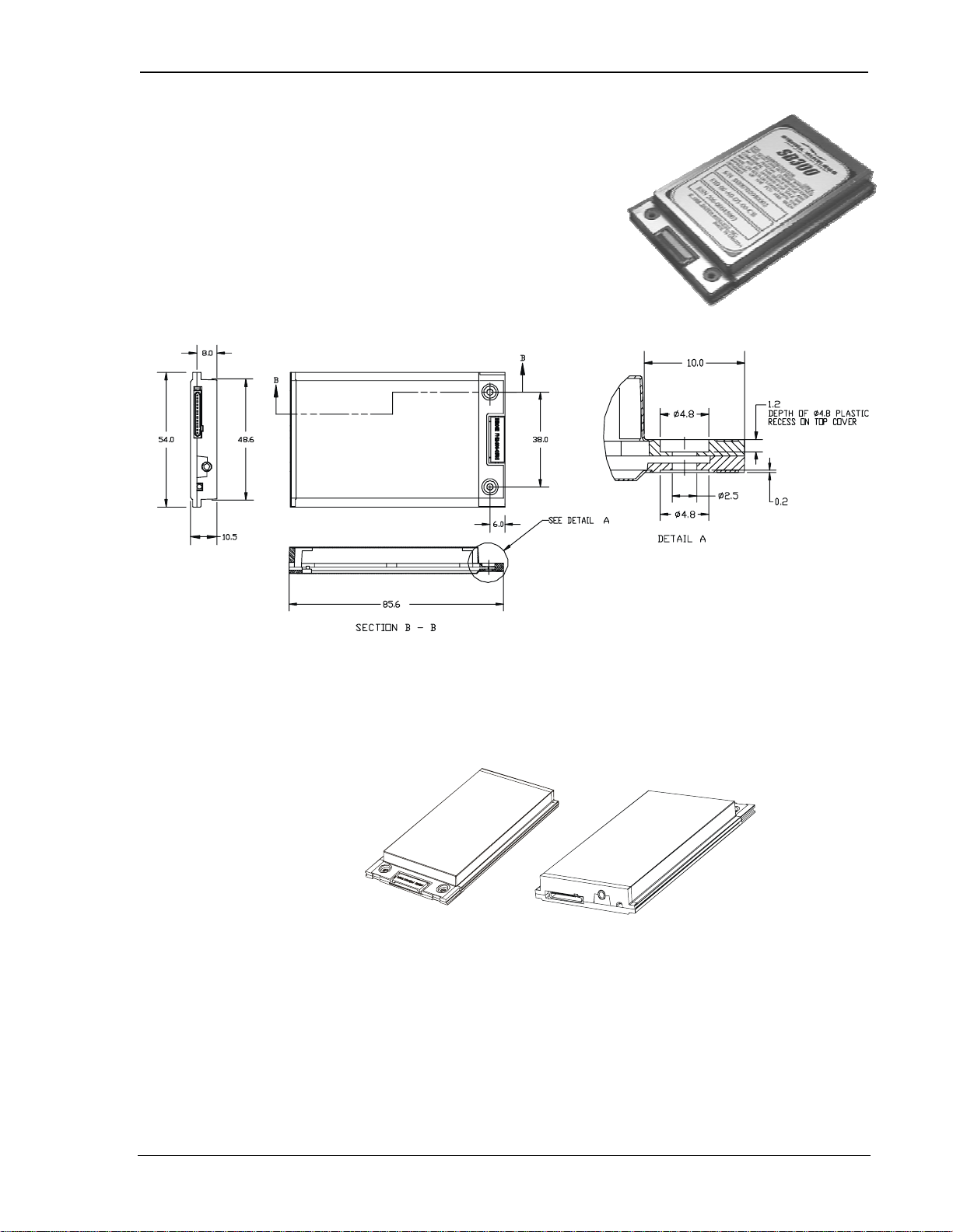
2.2.1.1. Physical Description
The SB300 comes in a Type III package, and includes a
30-pin, 0.5mm pitch ZIF connector for the host interface,
a MMCX connector for the antenna, and a status LED. Dimensions in millimetres are as follows:
2.2.1.2. Mounting
The SB300 uses an industry standard Type III frame-kit, and as such will fit into PC Card rails.
Alternatively, two clips or a bracket may be used to secure the module. There are also two
mounting holes provided on either side of the ZIF serial connector.
2.2.2. Connectors
2.2.2.1. Antenna Connector
The SB300 provides an MMCX type RF connector (Huber & Suhner 85 MMCX-50-0-1) for the
antenna connection. For proper matching the antenna should be 50 ohms with a return loss of
10 dB or better between 824 - 894 MHz. System antenna gain should be 0 dB.
2.2.2.2. Host (DTE) Connector
The SB300 provides a single 30-pin ZIF connector with 0.5mm pin spacing (Hirose FH12-30S).
2110059 Rev B Preliminar y 98.12.10 Page 5

OEM Developer’s Tool ki t Proprietar y and Confidential User’s Guide
2.2.3. Power Specifications
The SB300 requires +5V provided on pins 23-24, and ground provided on pins 23-28. Electrical
requirements and current specifications are identified below.
Table 2-1: Power and Current Specifications
Power Supply Requirements
Current Drain
+5Vdc
Maximum noise dc to 100 kHz: 10 mV
Sleep: 20 mA
Receive: 150 mA
Transmit (Full Power): 850 mA
2.2.4. Electrical
2.2.4.1. Host (DTE) Interface
The SB300 provides a single 30-pin ZIF connector with 0.5mm pin spacing (Hirose FH12-30S).
This connector provides four interfaces:
1. Se ri al host in terface
2. Modem control interface
3. Power
4. Status line interface
The connector pinouts are s p ecified in Table 2-2, an d el ectrical characteristi cs ar e s p ecified in
Table 2-3 Serial Interface Electrical Characteristics. Signal types are with respect to the
modem (DCE).
Table 2-2: Host Interface Conn ector P in ou t s
Pin Number P in Label Type Description
1 \DCD Output Data Carrier Detect
2 RxD Output Receive Data
3 TxD Input Transmit Data
4 \DTR In put Data Terminal Ready
5 GND Ground Ground
6 \DSR Output Data Set Ready
7 \RTS In put Rea dy To Send
8 \CTS Output Clear To Send
9 \RI Output Ring Indicator
10 \RESET Hardware Reset
11 RES ERVED Leave unconnected
12 \SHDN Input Graceful modem shutdown.
13 STATUS_OUT1 Output Power + RF Channel Status
14 STATUS_OUT2 Output Transmitter
15 STATUS_OUT3 Output Power Down OK
16 STATUS_IN1 Input
17 STATUS_IN2 Input
18 STATUS_IN3 Input
19 STATUS_IN4 Input
20 - 22 UNUSED
23 – 24 VBAT Input +5V
25 – 2 8 GND Ground Ground
29 UNUSED
30 RES ERVED Leave unconnected
5%
±
pp
Page 6 98.12.10 2110059 Rev B Preliminary

OEM Developer’s Tool ki t Proprietar y and Confidential User’s Guide
Table 2-3: Serial Interface E lectrical Characteristics
Characteristic Min.(V) Max.(V)
Input Low Voltage -0.3 0.8
Input High Voltage 2.5 5.0
Output High Voltage (Ioh=400 µA) 2.4 –
Output Low Voltage (Iol=3.2 mA) – 0.5
Serial Port Interface
The serial port pins comprise a standard set of serial data and handshaking lines. All signals are
negative assert i on, HCMOS logic compatible. These signals must be terminated properly if they
are not u sed. Refer to th e S B3 0 0 Series OEM M odems Integrator’s Guide for detail on
terminating unused lines.
Hardware handshaking should be enabled using CTS and RTS as the primary flow control signals.
The remaining handshaking lines (DCD, DTR, DSR, and RI) are, strictly speaking, not needed;
however they are desirable for TCP/IP stack usage and are supported for any applications that may
require them. Operation in each mode is as follows:
• RTS, CTS
Used as standard hardware flow control lines.
• DTR
Indicates to the modem that the host device is active. This line may also be configured to
switch the modem from data to command state or reset the modem (AT&D), and to enable
host wake-up. See the RI description below.
• DCD
This line is asserted while online. Behaviour options are set with the command AT&C.
• DSR
Always active when the modem is on; it is tied to logic GND.
• RI
If DTR is inactive (high), RI toggles when there is data for the host. This may be used to
wake-up the host.
The serial port should be configured for 8-data bits, no parity bits, and 1-stop bit. The default
DTE configuration will auto-baud to the host serial baud rate (based on speed of the ‘A’ in an AT
command). Host data rates of up to 57.6 kbps are supported. AT commands may be used to fix
the baud rate from 1200 bps to 57.6 kbps.
In command state, a terminal emulation program may be used to communicate with the modem
and change the configurat ion.
Modem Control Interface
Modem control is comprised of two inputs:
1. \SHDN: Graceful Shutdown
This is an active-low input. When activated this signal instructs the modem to de-register
from the network, and power down. When this activity is completed the
STATUS_OUT3 line is pulled indicating to the host that power may be removed from the
device.
2. \RESET: Hardware Reset
This is a hardware reset of the modem. This input should be externally pulled high and
driven low to reset.
2110059 Rev B Preliminar y 98.12.10 Page 7

OEM Developer’s Tool ki t Proprietar y and Confidential User’s Guide
Status Signal Interface
Status Outputs
Ther e are three status outp ut s provided, d efined as follows:
1. STATUS_O UT1 : Power, RF Channel Status
• Permanentl y low when power is on but no CDPD channel is visi ble.
• Pulses low once per second with 10% duty cycle if modem is locked onto a CDPD
channel.
• Pulses low twice per second with 10% dut y cycl e if modem i s registered on a CDPD
channel.
2. STATUS_O UT2 : Transmitter
• Low when the transmitter is k eyed.
3. STATUS_O UT3 : Power Down OK
• When low, this indicates it is safe to remove power to the modem. See Section 0
Modem Control Interface.
Status Inputs
There are four TTL-level status input lines provided. There are currently no features that use these
inputs.
Page 8 98.12.10 2110059 Rev B Preliminary

OEM Developer’s Tool ki t Proprietar y and Confidential User’s Guide
2.3. SB301 Specifications
Part number 1100029
To Be Determined.
2110059 Rev B Preliminar y 98.12.10 Page 9
OEM Developer’s Tool ki t Proprietar y and Confidential User’s Guide
2.4. SB302 Specifications
Part number 1100043
2.4.1. Mechanical
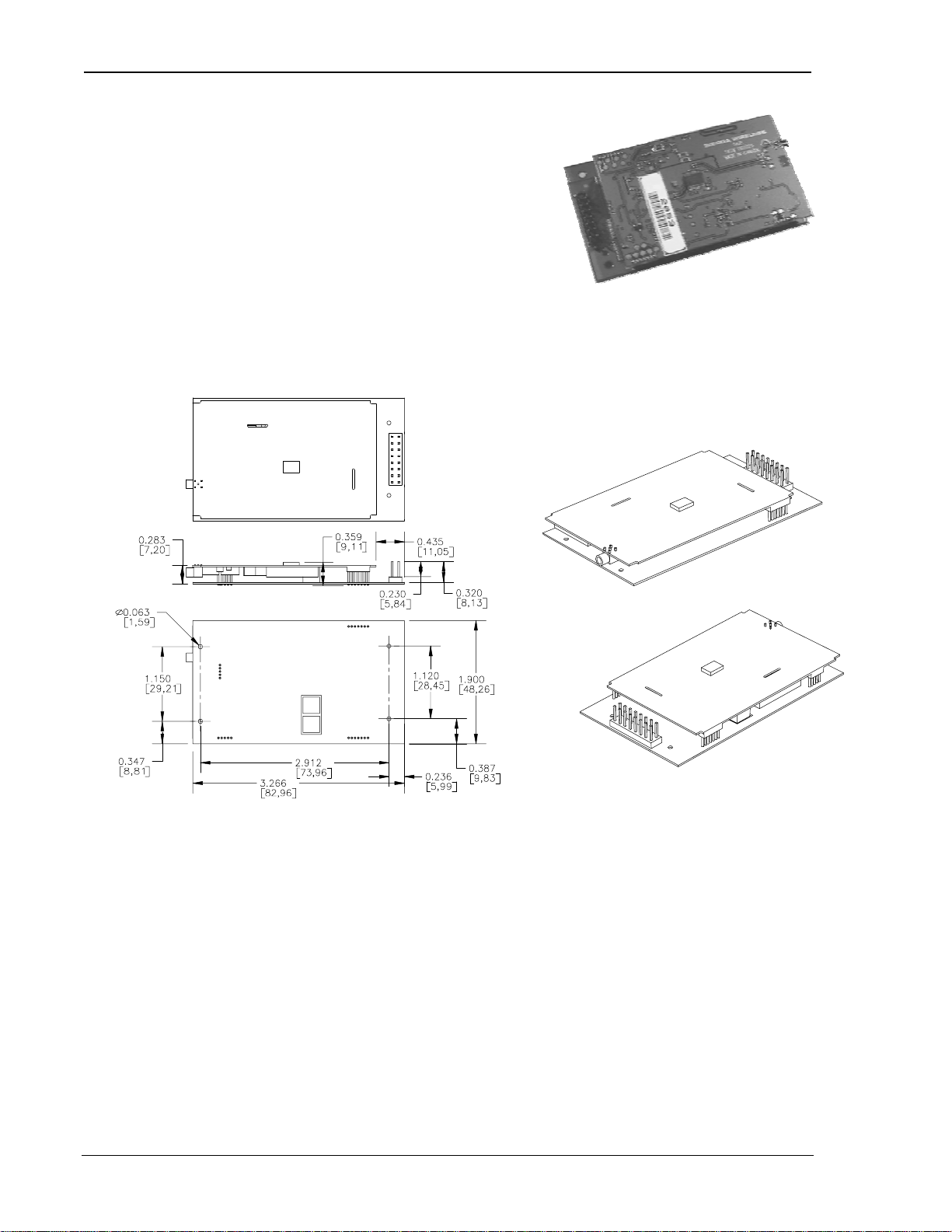
2.4.1.1. Physical Description
The SB302 comes as a board stack of two circuit
boards. It includes a 16-pin, 0.1” dual-row header for
the host interface and an MMCX style RF connector for the antenna. Dimensions in millimetres
are as follows:
Figure 2-1: Ph ysical d im ensions shown in inches [mm]. Figure 2-2: Assem bly View.
2.4.2. Connectors
2.4.2.1. Antenna Connector
The SB302 provides an MMCX type RF connector (Huber & Suhner 85 MMCX-50-0-1) for the
antenna connection. For proper matching the antenna should be 50 ohms with a return loss of
10 dB or better between 824 - 894 MHz. System antenna gain should be 0 dB.
2.4.2.2. Host (DTE) Connector
The SB302 provides a single (2 x 8) 16-pin connector (AMP 103186-8).
Page 10 98.12. 10 2110059 Rev B Preliminary

OEM Developer’s Tool ki t Proprietar y and Confidential User’s Guide
2.4.3. Power Specifications
The SB302 requires +5V provided on pins 1 and 2, and ground provided on pins 3 and 4.
Electrical requirements and current specifications are identified below.
Table 2-4: Power and Current Specifications
Power Supply Requirements
Current Drain
+5Vdc
Maximum noise dc to 100 kHz: 10 mV
Sleep: 20 mA
Receive: 150 mA
Transmit (Full Power): 850 mA
2.4.4. Electrical
2.4.4.1. Host (DTE) Interface
The SB302 provides a single 16-pin connector (Samtec HMTSW-108-22-T-D-440) that provides
four interfaces:
1. Se ri al host in terface
2. Modem control interface
3. Power
4. Status line interface
The connector pinouts are s p ecified in Table 2-5, an d el ectrical characteristi cs ar e s p ecified in
Table 2-6 Serial Interface Electrical Characteristics. Signal types are with respect to the
modem (DCE).
Table 2-5: Host Interface Conn ector P in ou t s
Pin Number P in Label Type Description
1 – 2 VBAT Input +5V
3 – 4 GND Ground Ground
5 TxD Input Transmit Data
6 RxD Output Receive Data
7 \DTR In put Data Terminal Ready
8 \DCD Output Data Carrier Detect
9 \DSR Output Data Set Ready
10 \CTS Output Clear To Send
11 \RTS Input Ready To Send
12 \RI Output Ring Indicator
13 \SHDN Input Graceful modem shutdown.
14 STATUS_OUT1 Output Power + RF Channel Status
15 STATUS_OUT2 Output Transmitter
16 STATUS_OUT3 Output Power Down OK
5%
±
pp
Table 2-6: Serial Interface E lectrical Characteristics
Characteristic Min.(V) Max.(V )
Input Low Voltage -0.3 0.8
Input High Voltage 2.5 5.0
Output High Voltage (Ioh=400 µA) 2.4 –
Output Low Voltage (Iol=3.2 mA) – 0.5
2110059 Rev B Preliminar y 98.12.10 P age 11

OEM Developer’s Tool ki t Proprietar y and Confidential User’s Guide
Serial Port Interface
The serial port pins comprise a standard set of serial data and handshaking lines. All signals are
negative assert i on, HCMOS logic compatible. These signals must be terminated properly if they
are not u sed. Refer to th e S B3 0 0 Series OEM M odems Integrator’s Guide for detail on
terminating unused lines.
Hardware handshaking should be enabled using CTS and RTS as the primary flow control signals.
The remaining handshaking lines (DCD, DTR, DSR, and RI) are, strictly speaking, not needed;
however they are desirable for TCP/IP stack usage and are supported for any applications that may
require them. Operation in each mode is as follows:
• RTS, CTS
Used as standard hardware flow control lines.
• DTR
Indicates to the modem that the host device is active. This line may also be configured to
switch the modem from data to command state or reset the modem (
host wake-up. See the RI description below.
• DCD
This line is asserted while online. Behaviour options are set with the command
• DSR
Always active when the modem is on; it is tied to logic GND.
• RI
If DTR is inactive (high), RI toggles when there is data for the host. This may be used to
wake-up the host.
AT&D
), and to enable
.
AT&C
The serial port should be configured for 8-data bits, no parity bits, and 1-stop bit. The default
DTE configuration will auto-baud to the host serial baud rate (based on speed of the ‘A’ in an AT
command). Host data rates of up to 57.6 kbps are supported. AT commands may be used to fix
the baud rate from 1200 bps to 57.6 kbps.
In command state, a terminal emulation program may be used to communicate with the modem
and change the configurat ion.
Modem Control Interface
Modem control is comprised of one input:
1. \SHDN: Graceful Shutdown
This is an active-low input. When activated this signal instructs the modem to de-register
from the network, and power down. When this activity is completed the
STATUS_OUT3 line is pulled indicating to the host that power may be removed from the
device.
Status Signal Interface
Status Outputs
Ther e are three status outp ut s provided, d efined as follows:
1. STATUS_O UT1 : Power, RF Channel Status
• Permanentl y low when power is on but no CDPD channel is visi ble.
• Pulses low once per second with 10% duty cycle if modem is locked onto a CDPD
channel.
• Pulses low twice per second with 10% dut y cycl e if modem i s registered on a CDPD
channel.
2. STATUS_O UT2 : Transmitter
• Low when the transmitter is k eyed.
3. STATUS_O UT3 : Power Down OK
• When low, this indicates it is safe to remove power to the modem. See Section 0
Modem Control Interface.
Page 12 98.12. 10 2110059 Rev B Preliminary

OEM Developer’s Tool ki t Proprietar y and Confidential User’s Guide
2.5. SB320 Specifications
Part number 1100033
2.5.1. Mechanical
2.5.1.1. Physical Description
The SB320 comes in a Type III package, and includes
a 30-pin, 0.5mm pitch ZIF connector for the host
interface, a 13-pin PCMCIA I/O connector for the
wirel ine inter fa ce, a MMCX connector for the antenn a, and a statu s LED. Dimensions in
millimetres are as follows:
2.5.1.2. Mounting
The SB320 uses an industry standard Type III frame-kit, and as such will fit into PC Card rails.
Alternatively, two clips or a bracket may be used to secure the module. There are also two
mounting holes provided on either side of the ZIF serial connector.
2.5.2. Connectors
2.5.2.1. Antenna Connector
The SB320 provides an MMCX type RF connector (Huber & Suhner 85 MMCX-50-0-1) for the
antenna connection. For proper matching the antenna should be 50 ohms with a return loss of
10 dB or better between 824 - 894 MHz. System antenna gain should be 0 dB.
2110059 Rev B Preliminar y 98.12.10 P age 13

OEM Developer’s Tool ki t Proprietar y and Confidential User’s Guide
2.5.2.2. Host (DTE) Connector
The SB320 provides a single 30-pin ZIF connector with 0.5mm pin spacing (Hirose FH12-30S).
2.5.2.3. Wireline Connector
The SB320 provides a single 13-pin PCMCIA I/O connector (ITT-Cannon CA112112-1) next to
the antenna connector on the side opposite the host (DTE) connector.
2.5.3. Power Specifications
The SB320 requires +5V provided on pins 23-24, and ground provided on pins 23-28. Electrical
requirements and current specifications are identified below.
Table 2-7: Power and Current Specifications
Power Supply Requirements
Current Drain Wireline Mode
Current Drain CSC Mode
Current Drain CDPD Mode
2.5.4. Electrical
2.5.4.1. Host (DTE) Interface
The SB320 provides a single 30-pin ZIF connector with 0.5mm pin spacing (Hirose FH12-30S).
This connector provides four interfaces:
1. Se ri al host in terface
2. Modem control interface
3. Power
4. Status line interface
+5Vdc
Maximum noise dc to 100 kHz: 10 mV
Inactive: 20 mA
Data/Fax Transmit: 220 mA
Voice Transmit: 250 mA
Receive: 100 mA
Transmit (Full Power): 850 mA
Sleep: 20 mA
Receive: 190 mA
Transmit (Full Power): 760 mA
5%
±
pp
The connector pinouts are s p ecified in Table 2-8, an d el ectrical characteristi cs ar e s p ecified in
Table 2-9 Serial Interface Electrical Characteristics. Signal types are with respect to the
modem (DCE).
Page 14 98.12. 10 2110059 Rev B Preliminary

OEM Developer’s Tool ki t Proprietar y and Confidential User’s Guide
Table 2-8: Host Interface Conn ector P in ou t s
Pin Number P in Label Type Description
1 \DCD Output Data Carrier Detect
2 RxD Output Receive Data
3 TxD Input Transmit Data
4 \DTR In put Data Terminal Ready
5 GND Ground Ground
6 \DSR Output Data Set Ready
7 \RTS In put Rea dy To Send
8 \CTS Output Clear To Send
9 \RI Output Ring Indicator
10 \RESET Hardware Reset
11 RES ERVED Leave unconnected
12 \SHDN Input Graceful modem shutdown.
13 STATUS_OUT1 Output Power + RF Channel Status
14 STATUS_OUT2 Output Transmitter
15 STATUS_OUT3 Output Power Down OK
16 STATUS_IN1 Input
17 STATUS_IN2 Input
18 STATUS_IN3 Input
19 STATUS_IN4 Input
20 – 22 UNUSED
23 – 24 VBAT Input +5V
25 – 2 8 GND Ground Ground
29 UNUSED
30 RES ERVED Leave unconnected
Table 2-9: Serial Interface E lectrical Characteristics
Characteristic Min.(V) Max.(V )
Input Low Voltage -0.3 0.8
Input High Voltage 2.5 5.0
Output High Voltage (Ioh=400 µA) 2.4 –
Output Low Voltage (Iol=3.2 mA) – 0.5
Serial Port Interface
The serial port pins comprise a standard set of serial data and handshaking lines. All signals are
negative assert i on, HCMOS logic compatible. These signals must be terminated properly if they
are not u sed. Refer to th e S B3 0 0 Series OEM M odems Integrator’s Guide for detail on
terminating unused lines.
Hardware handshaking should be enabled using CTS and RTS as the primary flow control signals.
The remaining handshaking lines (DCD, DTR, DSR, and RI) are, strictly speaking, not needed;
however they are desirable for TCP/IP stack usage and are supported for any applications that may
require them. Operation in each mode is as follows:
• RTS, CTS
Used as standard hardware flow control lines.
• DTR
Indicates to the modem that the host device is active. This line may also be configured to
switch the modem from data to command state or reset the modem (AT&D), and to enable
host wake-up. See the RI description below.
2110059 Rev B Preliminar y 98.12.10 P age 15

OEM Developer’s Tool ki t Proprietar y and Confidential User’s Guide
• DCD
This line is asserted while online. Behaviour options are set with the command AT&C.
• DSR
Always active when the modem is on; it is tied to logic GND.
• RI
In Wireline and CSC modes, this line toggles when there is an incoming call (the telephone is
ringing). In CDPD mode, if DTR is inactive (high), then RI toggles when there is data for the
host. This may be used to wake-up the host.
The serial port should be configured for 8-data bits, no parity bits, and 1-stop bit. The default
DTE configuration will auto-baud to the host serial baud rate (based on speed of the ‘A’ in an AT
command). Host data rates of up to 57.6 kbps are supported. AT commands may be used to fix
the baud rate from 1200 bps to 57.6 kbps.
In Circuit-Switched mode data state and any mode’s command state, a terminal emulation
program may be used to communicate with the modem and change the configuration.
Modem Control Interface
Modem control is comprised of two inputs:
1. \SHDN: Graceful Shutdown
This is an active-low input. When activated this signal instructs the modem to de-register
from the network, and power down. When this activity is completed the
STATUS_OUT3 line is pulled indicating to the host that power may be removed from the
device.
2. \RESET: Hardware Reset
This is a hardware reset of the modem. This input should be externally pulled high and
driven low to reset.
Status Signal Interface
Status Outputs
Ther e are three status outp ut s provided, d efined as follows:
1. STATUS_O UT1 : Power, RF Channel Status
• Permanentl y low when power is on but no CDPD channel is visi ble.
• Pulses low once per second with 10% duty cycle if modem is locked onto a CDPD
channel.
• Pulses low twice per second with 10% dut y cycl e if modem i s registered on a CDPD
channel.
2. STATUS_O UT2 : Transmitter
• Low when the transmitter is k eyed.
3. STATUS_O UT3 : Power Down OK
• When low, this indicates it is safe to remove power to the modem. See Section 0
Modem Control Interface.
Status Inputs
There are four TTL-level status input lines provided. There are currently no features that use these
inputs.
Page 16 98.12. 10 2110059 Rev B Preliminary

OEM Developer’s Tool ki t Proprietar y and Confidential User’s Guide
2.5.4.2. Wireline and Voice Interface
The SB320 provides a 13-pin connector (ITT-Cannon CA112112-1) for its wireline and voice
interface. The connector is positioned on the opposite end of the housing from the serial host
(DTE ) connector . Thi s con nector provides four interfaces:
1. Telephone Line Interface
2. Voice Interface
3. Debug Serial Port
4. Status Outputs
The connector pinouts are specified in Table 2-10. Specific configuration detail for the different
interfaces follow. Signal types are with respect to the modem (DCE).
Table 2-10: Pinout of Wireline and Voice Connector
Pin number Signal Name Type Description
1 Reser ved Leave Unconnect ed
2 SPKR– Output Speaker Interface negative
3 SPKR+ Output Speaker Interface positive
4 MIC+ Input Microphone input positive
5 MIC– Input Microphone input negative
6 Reser ved Input Leave Unconnect ed
7 Reser ved Input Leave Unconnect ed
8 STATUS1 Output Status Output 1
9 STATUS2 Output Status Output 2
10 GROUND Ground Signal Ground
11 RES ERVED Leave Unconnect ed
12 RING Input Wireline Connection
13 TIP Input Wireline Connection
Telephone Line Interface
The telephone line interface consists of two signals: TIP and RING. These two lines should be
routed via a twisted pair of wire to a panel-mounted RJ11 connector.
Voice Interface
Microphone Input
The microphone input is a capacitively connected differential input, with an input impedance
greater than 10 kohm. Microphone signals should be 90 mV
is available. If a single-ended drive is desired, the MIC– input may be connected to ground.
nominal. Software volume control
pp
Speaker Output
The speaker output is a differential signal used to interface to a speaker amplifier. The output
signal is ac-coupled 2 Vp-p nominal into a 150-ohm load. In circuit-switched and wireline data
and FA X mod es th is signa l is used to ind icate call pr ogress.
Debug Serial Port
This interface is shown as r eserved pins on the conn ector pin out table. The in terface is d es igned
to work through the Multipurpose Interface Board described in chapter
<???>.
Status Outputs
These signals are the status outputs from the host interface brought out on the wireline/voice
conn ector. They ar e described in Section 0 Status Signal Inter fa ce.
2110059 Rev B Preliminar y 98.12.10 P age 17

OEM Developer’s Tool ki t Proprietar y and Confidential User’s Guide
2.5.5. SB320 Communication Mode Specifications
2.5.5.1. Wireline Specifications
Wireline Data CCITT V.34: 33600 – 2400 bps
CCITT V.32bis: 14400, 12000, 7200 bps
CCITT V.32: 9600, 4800 bps
CCITT V.22bis: 2400 bps
CCITT V.22: 1200 bps
CCITT V.21: 300 bps
Bell 212A/103: 1200, 300 bps
V.42 error correcti on (LAPM and MNP)
V.42bis and MNP5 data compression
Wireline FAX Command Set: EIA/TIA 578 Class 1
CCITT V.17: 14400, 12000, 9600, 7200 bps
CCITT V.29: 9600, 7200 bps
CCITT V.27ter: 4800, 2400 bps
CCITT V.21 Channel 2: 300 bps
Wireline Voice
2.5.5.2. Circuit-Switched Data Specifications
CSC Data
CSC FAX Command Set: EIA/TIA 578 Class 1
CSC General IS-91
CSC Voice IS-19C
2.5.5.3. CDPD Specifications
CDPD Version CDPD 1.1
CCITT V.34: 16800 – 2400 bps
CCITT V.32bis: 7200 bps
CCITT V.32: 9600, 4800 bps
CCITT V.22bis: 2400 bps
CCITT V.22: 1200 bps
CCITT V.21: 300 bps
Bell 212A/103: 1200, 300 bps
V.42 error correcti on (LAPM and MNP)
V.42bis and MNP5 data compression
ETC
CCITT V.29: 9600, 7200 bps
CCITT V.27ter: 4800, 2400 bps
CCITT V.21 Channel 2: 300 bps
Page 18 98.12. 10 2110059 Rev B Preliminary

3. Multipurpose Interface Board
3.1. Introduction
The Multipurpose Interface Board (MIB) is a development aid to facilitate testing and
configuration of the SB300 Series modems by allowing communication using a standard RS-232
serial connection. It also provides monitoring LEDs, test points, connections for a protocol
analyzer, and connections for wireline (PSTN) hookup.
Although the MIB provides support for the full SB Series of modems, it is not intended to support
more than one modem at a time.
For a quick initial setup go to Section 3.8.1. To get a fuller understanding of the board’s
connections and capabilities sections are provided as follows:
• Section 3.2 Board Description with schematic and parts layout reference.
• Section 3.3 Power Supply including voltage control and supplying power from a host device.
• Section 3.4 Connections desc ribing the various hos t, mode m, and a nalyzer connectors.
• Section 3.5 Jumpers details options and setups.
• Section 3.6 Serial Breakout Box describes cross wiring correction and signal checking
• Section 3.7 Test Points identifies what is offered and where to find it
3.1.1. Features
The MIB offers these featur es :
• Supports SB220, SB300, SB301, SB302, SB320
• RS232 to 5V HCMOS conversion
• Intercept ion of 5V HCMOS control signals from host to modem to verif y synta x and levels
• Intercepted signals are converted to RS-232 for observation by standard serial port
• Supports wireline access
• Supports voice headset
• Serial port breakout box to resolve cabling difficulties
• Serial port stat u s LEDs
• Status line LEDs and pullup down
• Current, DISC and KEY test point s
• Annunc iator to he ar dial tone s
• Comm Ana lyzer connectors - 2 5 pin protocol an alyzer
• Debug port serial connector
• Uses wall adapte r for power
3.2. Board Description
3.2.1. Schematic
<Image(s) to be inserted>
3.2.2. Parts Layout
<Image to be inserted>
2110059 Rev B Preliminar y 98.12.10 P age 19

OEM Developer’s Tool ki t Proprietar y and Confidential User’s Guide
3.3. Power Supply
The MIB requires a 12Vdc, 1 Amp power supply. An AC adapter (part number 1900000) is
provided with the OEM Developer’s Toolkit.
This power is converted by the MIB into the 5V and 7V supplies needed by the modem. It is not
designed to support more than one modem connected to the MIB at any time.
There is a power switch on the MIB that controls delivery of both the 5V and 7V supplies to the
modem connectors but DOES NOT control the 5V supply to the MIB’s own logic. The MIB’s
logic i s on whenever the 12V suppl y is connect ed.
The normal initial setup has jumper J21 (Power Select) set on pins 1 and 2 which will deliver
power to the modem from the MIB’s power source.
3.3.1. Voltage Adjustment
A trim-pot is provided to make fine adjustments to the 5V supply in order to both regulate and test
the modem under various power conditions. The 7V supply does not have adjustment controls.
The 5V supply can be measured at pin 1 of the power select jumper (J21).
NOTE: At this time the 5V power adjustment will also affect the 5V supply to the MIB’s own
logic. Extreme settings may cause failures of the MIB that should not be interpreted as failures of
the modem.
3.3.2. Using Power from Host (DTE)
For users testing a host connection to a SB301 or SB302, it is possible to power the modem from
the host (DTE) device rather than the MIB. To do this, connect the host to the 2x8-pin block
(J9 SB301/302 To Host) and set jumper J21 (Power Select) to pins 2 – 3 (+5V Host).
At this time, there is no provision for a similar host connection to the SB300 or SB320. These
modems do however derive power from the source set by jumper J21 (Power Select) so this must
be set to pins 1 – 2 for normal operation. A workaround to allow host power to supply the modem
is to patch the host power to pins 1 and 2 of the SB301/302 host connector block (J9) and set the
power select jumper (J21) to pins 2 – 3.
The MIB’s 12V power supply must remain on to deliver power to the RS-232 / HCMOS
conversion logic. The DTE/DCE serial lines are converted to RS-232, made available at the Serial
Breakout Box, an d th en converted back to HCMOS at each end.
3.4. Connections
This sect ion provides information on the use of th e va rious connectors on the M IB.
3.4.1. PC Host (DTE) RS-232 Serial Connection
There are two 9-pin D connectors (female) provided on the MIB to connect to standard RS-232
serial ports on a host terminal, usually a PC.
PC Serial Port
This connection is for a PC host device running a terminal emulation program. Communication to
and from this port is delivered via the Serial Breakout Box, to and from the modem.
Debug Port
The secon d 9-pin D connector is for factor y level testing only.
Page 20 98.12. 10 2110059 Rev B Preliminary

OEM Developer’s Tool ki t Proprietar y and Confidential User’s Guide
3.4.2. Host (DTE) Connection for SB301 / SB302
An alternative to the 9-pin RS-232 serial connector (PC Serial Port) is provided for connecting a
host (DTE) device to a SB301 or SB302 via the 2x8-pin block at J9 (SB301/302 To Host). This
connector allows you to insert the MIB between the host and the modem for testing and
monitoring communications.
Although there is not currently an equivalent 30-pin ZIF host connector for the SB300 and SB320,
the pins of this connector are also delivered to the SB300 / SB320 modem connectors.
This connector i s HCMOS level.
Serial Signals
The MIB converts the serial communication signals to RS-232 level, presents them at the Serial
Breakout Box and then conver t s them back to HCMOS level before pa ssing them to the DTE/DCE
ends.
NOTE: In order for this signal conversion to work, the host device MUST supply +5V on pins
1and 2. It is this power which enables the conversion logic on the MIB for the host side.
Input Signals
The modem ‘s three STATUS_OUT signals are passed directly between the modem and the host.
They can also be monitored by the three LEDs (SO1, SO2, SO3)
Output Signals
The host Shutdown signal is passed to the modem via an enabling jumper (HOSTSHDN EN) on
the main jumper bl ock. With the jumper removed, the shutd own signal is disabled .
Power from the host can be used to power the modem by setting jumper J21 (Power Select) to pins
2 –3 (+5V Host). With the jumper in the original position (pins 1 – 2) the modem is powered from
the MIB. See Section 3. 3 .2 for details.
3.4.3. Protocol Analyzer Connection
Two 25-pin D connectors are available to connect a protocol analyzer in the serial signal path.
The female connector is on the PC side of the Serial Breakout Box; the male connector is on the
modem side.
To monitor the comm unicati on s i gn als between the host an d m od em, simply con nect the an alyzer
to the MIB.
3.4.3.1. Analyzer DCE Emulation
If needed to test the host side, the modem can be disabled and the analyzer allowed to function as
the modem (DCE) device.
3.4.3.2. Analyzer DTE Emulation
The protocol analyzer can be used to emulate the host (DTE). The setup to do this is still to be
determined.
The setup for DCE emulation is still to be determined.
3.4.4. SB300 / SB320 Modem Connection
Both the SB300 and SB320 use a 30-pin ZIF connector. The connector uses the flex ribbon (part
number 2000068) provided with the OEM Developer’s Toolkit.
The connection provides all defined pinouts (see the Product Descriptions in Chapter 1 for details)
DISC output from the modem on pin 30 which is made available at test point TP1 (DISC)
plus a
just beside the con nector.
2110059 Rev B Preliminar y 98.12.10 P age 21

OEM Developer’s Tool ki t Proprietar y and Confidential User’s Guide
Use care when attaching the ribbon to the connector. There is a cover clamp that hinges up to
open the conne ctor. Slide t he ri bbon into the connector with covered ( black) si de of th e ribbon
facin g up. Close the con nector clamp by press ing down at th e en d s ra ther than the centre of
clamp. The mode m has an identical clamp connector.
This connector i s HCMOS level.
Serial Signals
The MIB converts the serial communication signals to RS-232 level, presents them at the Serial
Breakout Box and th en passes them to the DTE /DCE ends.
The DCE (m od em) side of this conver s ion can be di s abled, effectivel y dis connect ing the modem
from the MIB by placing a jumper on the MODEM DISBL pins of the main jumper block. This
can be useful if you ar e using a pr ot ocol analyzer to emulate the DCE devi ce.
Input Signals
The 5V power comes from the MIB via the jumper J21 (Power Select). Pins 1 – 2 will con nect the
MIB adjustable 5V supply.
All other input signals (Shutdown (/SHDN) and Status 1 – 4) to the modem are supplied from the
main jumper block. Placing a jumper on the pins will make the signal active.
Output Signals
The three modem ST AT US_OUT signa ls are indicated by th e th ree LEDs ( SO 1, SO2, SO3).
These are lit when the output s ignal is a ctive.
3.4.5. SB301 / SB302 Modem Connection
The SB301 and SB302 use a 2x8 pin connector block. A strap with connectors at each end (part
number 2000067) is provided with the OEM Developer’s Kit. This strap allows connection of the
modem to the MIB at J7 (To SB301/302).
This connector i s HCMOS level.
Serial Signals
The MIB converts the serial communication signals to RS-232 level, presents them at the Serial
Breakout Box and th en passes them to the DTE /DCE ends.
The DCE (m od em) side of this conver s ion can be di s abled, effectivel y dis connect ing the modem
from the MIB by placing a jumper on the MODEM DISBL pins of the main jumper block. This
can be useful if you ar e using a pr ot ocol analyzer to emulate the DCE devi ce.
Input Signals
The 5V power and Shutdown (/SHDN) signal to the modem can be supplied from the Host (DTE)
connection, not the PC Host RS-232 connection.
Modem power can be drawn from either the MIB or the host (DTE) by setting the jumper J21
(Power Select). Pins 1 – 2 will connect the MIB adjustable 5V supply. Pins 2 –3 (+5V Host) will
conn ect the host p ower to the modem. See Section 3.3.2 for d etails.
The Shutdown (/SHDN) signal must orig ina t e from th e Host (DTE) conn ection (not the PC Host
RS-232 connection). It can be enabled or disabled via a jumper (HOSTSHDN EN). With the
jumper connector in, the shutdown signal will be passed to the modem.
The Shutdown sign al can also be orig inated at the MIB using the SB3XX SHDN jumper on the
main jumper block. Placing a jumper on the pins will make the signal active.
Page 22 98.12. 10 2110059 Rev B Preliminary

OEM Developer’s Tool ki t Proprietar y and Confidential User’s Guide
Output Signals
The three modem ST AT US_OUT signa ls are passed directly between the modem and the Host
(DTE ) connector . Th eir s tatus is al s o be indicated by the three LEDs (SO1, SO 2, S O3) . Th es e are
lit when the output signal is active.
3.4.6. SB220 Modem Conneciton
This is provided for factory testing of older model modems.
3.5. Jumpers
Ther e are three jum p er blocks pr ovid ed on the MI B. The ma in jumper block is locat ed next to the
modem power switch and has eight pairs of pins. There is also a 3-pin jumper block for power
selecti on, and a 2-pin jumper bl ock to enabl e or disable the built- in s p eaker.
3.5.1. Main Jumper Block
The main jumper block (J24) has eight pairs of pins, all labelled. The first four pairs are to
activate the four input signals of the SB320 (not currently implemented by the modem). Two
pairs are for direct MIB activation of the Shutdown (/SHDN) signal to the modems and to enable
the SB301/302 host interface to trigger this signal. There is one pair of pins for activating TP3
and the last pair is to disable the modem side of the RS-232 / HCMOS serial signal conversion.
3.5.1.1. ST INx – Status Inputs
Placing a jumper on one of these pins will force the signal active. At this time none of the status
input signals are used by the SB320.
3.5.1.2. HOSTSHDN EN – Host Shutdown Enable
This jumper will enable the Shutdown (/SHDN) signal from the SB301/302 host interface to be
passed to the modem. Without the jumper installed, the signal will not reach the modem.
3.5.1.3. SB3XX SHDN – Shutdown
The modem’s Shutdown (/SHDN) input can be forced active by placing a jumper on this pair of
pins. This will work regardless of the setting on the HOSTSHDN EN jumper.
3.5.1.4. TP CTRL
Test Point 3 is tied to this jumper. Applicatio n TB D.
3.5.1.5. MODEM DISBL
Placin g a j umper on th is pair of pins wil l disable the MIB’s con ve rsi on of the modem serial
connection from HCMOS level to RS-232 level, effectively disconnecting the modem from the
Seri al Breakout Box and the host. Power and con trol signals remain in tact.
This can be used to dis able the modem’s seri al connect ion while u s in g a protocol an alyzer to
emulate the modem .
3.5.2. Power Select
A 3-pin block is provided to select the source of the +5V power supply to the modems. Placing
the jum per on pins 1 and 2 will connect the MIB’s reg u lated +5V s u pp l y. P la cing the jum p er on
pins 2 and 3 will connect the modem to power from the SB301/302 Host connection.
2110059 Rev B Preliminar y 98.12.10 P age 23

OEM Developer’s Tool ki t Proprietar y and Confidential User’s Guide
The modem power switch comes AFTER the power selection jumper and can be used to control
power to the modems regardless of the source of the power.
3.5.3. SPK EN – Speaker Enable
A 2-pin block is provided near the status indicator LEDs to allow you to disable the speaker in
situations where you would prefer to mute the output. Placing the jumper on the pins will enable
the SB320 to drive the speaker, provided the SB320 I/O connector is in place.
The SB300/301/302 modems do not provide speaker output.
3.6. Serial Breakout Box
One of the main functions of the MIB is to provide a means of monitoring the serial connection
between a host and the modem. The MIB convert s HCMOS level si gn al s at th e modem (and at
the SB301/302 Host connection) to RS-232 level for monitoring on the LEDs and with a protocol
analyzer.
In addition, the two rows of pins on each side of the DIP switch provide test points and
connections to each individual signal. This allows you to cross connect pins to correct cabling or
conn ector faults.
3.6.1. DIP Switch
The DIP switch is used to make or break the connection between the host and modem for each of
the serial commun ication signals . Wh en switched to the open sid e, the conn ection is br oken.
Should there be a cross connection error in the host / modem serial connection, switch off the
affected signals and use the breakout pins to bridge the signal correctly.
The las t two switch es are not conn ected.
3.6.2. Serial Connection Indicators
The LED indicators show the status of the serial communication on the modem side of the
break out box. Red in di cates an in active sign al, green in d icates an a ctive one. All LEDs are
labelled.
3.7. Test Points
Ther e are four test p oints plus a pa ir of pins for current mea s urement.
3.7.1. TP1 DISC
This t est point r ecei ves its si gnal from pin 3 0 of the SB320 modem connector and pin 1 of the
SB320 I/O connector. It presents the discriminator output of the radio modem.
3.7.2. TP2
Connected to the SB320 pins 20, 21, and 22, these signals are currently unused.
3.7.3. TP3
This is connected to the TP CTRL jumper of the main jumper block. Application to be
determined.
Page 24 98.12. 10 2110059 Rev B Preliminary

OEM Developer’s Tool ki t Proprietar y and Confidential User’s Guide
3.7.4. TP4 KEY
All modem connectors provide the transmitter key indicator here. This signal is also indicated by
the S02 status LED.
3.7.5. Current Measurement
Two pins are made available at J26 (Current Measurement) to allow connection of an ammeter to
measure the current drawn by the modem.
3.8. Applications
To Be Determined.
3.8.1. Initial Setup
As shipped the MIB is configured as follows:
• Seri al communi cation DIP swi tches are closed and the two spar e s witches ar e l eft open.
• Power select is on pins 1 and 2 to use MIB p ower for the modem.
• All main ju mpers a re re move d .
• The speaker is enabled.
2110059 Rev B Preliminar y 98.12.10 P age 25

4. Getting Started
4.1. Introduction
This chapter guides you through the initial physical setup of a host terminal (usually a PC), the
Multipurpose Interface Board (MIB), and a modem. Related start-up issues such as cellular
activation are als o cov e re d .
After completing this setup, you should be able to communicate with the modem with AT
commands.
The following chapter (Software Installation) will deal with the software installation on a host PC
of Watcher™ and WirelessExpert™ which make further configuration of the modem and testing
on a CDPD network (if applicable) mu ch simpler .
4.2. Registration
In order to use your modem for wireless communication you must register it with a cellular
service provider. This section describes what they will need to know and what information they
will provide to you.
Contact your service provider to get the registration process started. While the service provider is
getting your account configured, you can install and configure your modem. Record the
informa tion provi ded by your ca rrier for conf iguring the modem later.
In an y cover age area there can be two provider s, each assigned to a “si d e” (A or B) of the cellular
waveband. Each pr ovider i s al so assign ed a Service Provider Network Identi fier (SPNI) number.
4.2.1. CDPD
In order to use your modem in CDPD mode it must be activated on a CDPD network by a service
provider. To register your modem for Wireless IP activation on CDPD networks, contact your
local CDPD service provider .
Give the CDPD service provider the Equipment Identifier (EID). This is the identificatio n
number of the radio/modem. The EID has the following format: 00-A0-D5-xx-xx-xx. Look for
this number on the back of your modem and on a label affixed to the outside of the package that
the modem was shipped in. The number is also available by querying the modem with the
AT+WPEID
The CDPD service provider suppl i es the following:
CDPD Service Providers Toll-free Number
AmeriTech 888 – 907 – 3282
AT&T Wireless 800 – 552 – 3373
Bell Atlantic Mobile 800 – 308 – 3282
Go America 888 – 462 – 4600
GTE Wireless 800 – 483 – 6625
Sierra Wireless, Inc.
command.
doe s not r ec o m m end or en dorse an y pa rt icular pr o vider.
2110059 Rev B Preliminar y 98.12.10 P age 27

OEM Developer’s Tool ki t Proprietar y and Confidential User’s Guide
5. Modem address, sometimes referred to as a Network Entity Identifier (NEI) . Th is may also
be refe rred t o as your Internet Protocol (IP) address. This identifies your modem on a CDPD
network and on the Internet.
6. IP address of a router or server to ping when t es ting the connection .
Both of the above items are in the form of an IP number. This is made up of four numbers
ranging in value from 0 to 255, separated with periods (sample: 192.168.0.9)
7. Side designat or, A or B. This determin es the channels used by your CDPD service pr ovider.
8. SPNI number of the provider.
This information will be required when configuring your modem for CDPD registration either
with WirelessExpert or AT commands.
4.2.2. CSC (AMPS)
In order to use your modem in CSC mode it must be activated with a cellular phone service
provider. To register your modem for CSC activation, contact your local cellular carrier.
Give the service provider the Electronic Serial Number (ESN). This is the identificatio n number
of the radio/modem. The ESN has the following format: 206-xxxxxxxx. Look for this number on
the back of your modem and on a label affixed to the outside of the package that the modem was
shipped in . The nu mber is als o available by query ing t he modem w ith the
The cellular service provider supplies the following:
1. A Number Assignment Modul e (NAM). This is you r cellular telephone nu mber and H ome
cellular System Identifier (SID).
2. Sid e designat or, A or B. This determin es the ch a nnels used by your service provider.
AT+WPEID
comma n d .
This information will be required when configuring your modem for CSC mode use either with
WirelessExpert or AT commands.
4.3. Setup Considerations
4.3.1. Host Computer Terminal
You will require a PC with a communications program capable of operating in ASCII terminal
emulation mode. This allows the PC to function as a terminal attached to the modem and permits
the entering of AT commands required for modem setup and diagnostics. It is recommended that
the program chosen be capable of logging terminal communications activity to a file for later
analysis or printout in the event that technical support is required.
For IBM PC - com patibles , Windows Terminal, Hyperter minal, Procomm, an d Ker mit are all
acceptable.
A 9-pin D connector RS-232 serial cable (part number 006.0011) is provided with the OEM
Developer’s Kit for conn ecting the PC h ost to the Multipurpose Interface Board.
4.3.2. Physical considerations
The MIB and modem can be sensitive to static so the setup should be in a static controlled
environment.
4.3.3. Antenna considerations
The SB300 Series modem uses standard mobile cellular radio signals. An antenna (part
number 1810009) is provided with the OEM Developer’s Kit. Along with this antenna is a
connector adapter (part number 2000066) to convert the antenna connector (Female SMA) to
match the modem req uirement (Male MMCX).
Page 28 98.12. 10 2110059 Rev B Preliminary

OEM Developer’s Tool ki t Proprietar y and Confidential User’s Guide
You can us e a n ant en na of your own if you c hoos e. Any standa rd cellular antenn a of good quality
with a maximum gain of 3 dB (FCC requirement) will function properly provided you have a
suitable connector.
Antenna performance is subject to the following guidelines:
Location – Locate the antenna as far away from personnel as possible to minimize signal
blocki ng. For opti mu m reception, in indoor fixed l ocation applications, position the antenna
above the height of personnel and nearby equipment or structures. Locate the antenna as close to a
win dow as p os s ible.
Cabling – Select a low loss, high quality, 50-ohm, coaxial cable with the appropriate connectors.
The cabl e can be any length, but lengths gr ea ter than 3. 7 met res (12 feet) increase cable l oss and
offset the antenna’s nominal gain. If longer length cable s are requi red, use a heavier w ire gauge to
redu ce the dB loss/m an d to minimiz e the effect of the cable loss on ant enn a gain.
Ground Plane – For installations where a good antenna ground plane (metal surface) is not
available, use a non-ground plane type of antenna to help maximize signal reception.
Proximity to Other Antennas – In general, do not locate the SB300 Series modem and its
antenna closer th an 1.5 metr es ( 5 feet ) to another antenna. In certain cases even m ore separat ion is
requ ired. The effect o f t he inter ference from two-way transmitters varies from slowing down
response times to blockin g modem transmission.
4.4. MIB Presets
The Multipurpose I nterface Board ha s several swit ches and jum pers whi ch sh ould be config u red
as follows for the initia l setup.
• DIP Switch in the Serial Break out Box:
Swit c hes 1 t hrou gh 8 shou ld be closed
Switches 9 and 10 open.
• Power Select (J21) should be on pins 1 – 2 (+5V).
• Jumpers on J24 should all be off.
• Speaker Enable should be on.
4.5. Connections
This section describes the steps to connect the PC host, MIB, and modem. At the end of this
procedu re you sh ould be ready to con figur e an d u se the modem. If res u lts at any step are not as
describe d, consult th e ch apt er on tr oubleshooting.
To connect follow these step s:
3. Attach the RS-232 serial cable from the host to the MIB
The Serial Breakout Box indicators for DTR, TxD, and RTS should all light (powered from
the RS-232 connection).
4. Star t the termin al application on th e host PC. Config ure the applicati on for the port connected
to the MIB. We recommend a setting of 19200 bps, 8 data, no parity, 1 stop, with hardware
(RTS/CTS) flow control.
5. Instruct the terminal application to connect.
The DTR an d RTS indica tors shoul d be gr ee n. The T xD ind icat or should be red.
6. Attach the appropriate modem connector strap to the MIB port for the modem to be used.
• 2x8-pin ribbon with connectors for the SB301 and SB302
PC Serial Port
connector (J1).
<photo>
• 30-pin 5mm flex strap (without connectors) for the SB300 and SB320.
To make the SB300/320 connection:
2110059 Rev B Preliminar y 98.12.10 P age 29

OEM Developer’s Tool ki t Proprietar y and Confidential User’s Guide
i. Open the hinged SB300/SB320 connector on the MIB by lifting it away from the
edge of the board.
ii. Slide the strap into the connector with the contact side down (black side up). Be
sure it is fully inserted.
iii. Close the conn ector by pressing down on th e en ds of the connector rather than th e
centre.
7. Attach the modem to the connector strap.
NOTE: The MIB is not designed to support more than one modem connected at any time.
Connecting more than one modem may damage the modem or MIB.
8. Place the antenna is a suitable location, attach the antenna connector adapter to the antenna
cable, and attach the cable to the modem.
9. Connect the 12Vdc power supply to the MIB.
10. Switch on the modem power using the POWER switch on the MIB.
The remaining Serial Br eakout Box in dicators shoul d li ght.
The Status indicators will come on in turn as the modem firmware starts up
The modem should send an OK prompt to the host PC.
11. Type AT<enter> at the host terminal. The modem should reply with OK.
The modem is now ready to be used with the host computer.
<photo>
<photo>
<photo>
Page 30 98.12. 10 2110059 Rev B Preliminary

5. Software Installation
5.1. Introduction
This chapter provides instructions for installing Watcher™ and WirelessExpert™ on a host PC
and using these programs t o configur e an d us e the modem.
Running WirelessExpert is required to install necessary drivers on the host PC.
Watcher
Watcher is a Windows application that configures and monitors Sierra Wireless modems for
CDPD, Circuit Switched Cellular (CSC), an d Wir elin e oper a ti on. It al so all ows you to set the NEI
and NAM registrations for your modem and test the host connection. This chapter explains how
to install Watcher and describes basic Watcher operat ions and important screen elem ents.
WirelessExpert
Installation of the drivers required for modem operations is performed with an installation wizard
called WirelessExpert. This can be run at any time to view and edit the cellular activation settings
(NAMs, NEIs, etc.)
5.2. Installing Software on the Host
On the host PC:
1. Insert the diskette.
2. Select
3. Enter
Start > Run…
A:\Setup
An installation wizard will guide you through the process.
from the Windows taskbar.
A menu entry is added to the Start > Programs menu:
5.2.1. Configuration using WirelessExpert
WirelessExpert will locate the modem on a COM port, interrogate it for features, and install the
required drivers on your host PC. It will then allow you to set or alter the cellular activation
settings.
In order for the drivers to be available to the Windows operating system, the PC will be restarted
part way through the execution of WirelessExpert. This is done automatically but does require
that n o other progr ams are running on the PC at the time.
Preparation:
1. Close any open applicati on s on the host PC in cluding any communication prog r am connect ed
to the modem. The system restart supervised by WirelessExpert may fail if other programs
are running.
2. Ensure the host serial connection to the modem via the MIB is in place and the modem power
is on. The full set of serial communication LED indicators should be on.
Installation:
2110059 Rev B Preliminar y 98.12.10 P age 31

OEM Developer’s Tool ki t Proprietar y and Confidential User’s Guide
3. Select Start > Programs > Watch er > Wirel essE xpert from the Windows taskbar.
4. Select the modem being used from the list:
SB320 – OR – SB300 Series for the SB300, 301, 302
5. Click Next > and th en N
products. WirelessExpert then locates the com port connected to the modem and finds the
related registry entries for it. The results are shown.
6. Click Next > to have WirelessE x p er t install the appropr i ate driver s for the modem .
7. A messa g e ap pears advi s ing of the n eed to res tart the computer. Click OK. WirelessExpert
shuts d own the computer and rest ar ts it for you.
8. Click Next > until you pass the section on connectivity components. WirelessExpert now
examines the mod em for cellu lar netw ork activ ation.
9. The next page allows you to set the level of access to the configuration settings which will be
allowed to the Watcher program. Setting full access will allow Watcher to alter the NAM /
NEI settings, read-only will allow Watcher to display the settings but you will have to use
WirelessExp er t or d irect AT commands to alter settings.
10. For SB320 installations, the NAM entries for CSC activation will be presented for entry and
editing. This screen is skip p ed for CDPD only modems.
11. The CDPD settin gs of the modem ar e displa yed for entry an d editing . A radio button set s the
active NEI for use. A pull-down menu allows setting of the channel side preference.
12. The CDPD settin gs can be tested b y Wirel essEx p ert and set up in th e Windows Dial-up
Networking Connection facility. A pull-down menu allows you to select the NEI for testing.
If you select one di fferent fr om the radio but ton selection on the previous screen, the new
setting will become the default. The test can be skipped if desired.
13. Click Finish to complete the WirelessExpert configuration. The modem should now be ready
for use.
ext > again to skip the page regarding setup of other modem
5.3. Using Watcher for Remote Connections
Starting Watcher will open a connection using the settings in the Dial-up Networking facility of
Wind ows. To start Watcher:
Select St art > Programs > Watcher > Watcher fr om th e Windows ta skbar.
Watcher will locate and initialize the modem.
5.3.1. Configuring Watcher
Watcher has a setup dialog that lets you verify the Sierra Wireless modem connection to the COM
port, and the basic configuration strings for Circuit Switched Cellular and Wireline operation.
To set up Watcher:
14. Make sure the modem is powered on and is communicating with your PC.
15. Select Options > Setup Watcher from th e Watcher main menu
This will open the Setup Watcher dialog.
16. Click the WirelessExpert… button to activate the installation wizard described above or
make changes to the settings manually.
17. If specialized setup strings are required for your installation, you can enter them here. The
modem uses configuration strings to optimize its operation in certain modes. The modem
comes pr es et with the most common configur ation strings. See
<???> for more information.
Page 32 98.12. 10 2110059 Rev B Preliminary

OEM Developer’s Tool ki t Proprietar y and Confidential User’s Guide
CDPD mode does not offer specia l set up s. To control CDPD mode use Options >
Setup CDPD… described below.
18. Click OK to save the configuration and return to the Watcher program window.
5.3.2. Configuring Cellular Settings using Watcher
WirelessExpert must be run initially to properly install and register the required connectivity
components with Windows. If you have not run WirelessExpert on the host PC to be used with
the modem it must be done before using Wa t cher.
Watcher’s ability to manage the cellular activation settings of the modem are set by
WirelessExpert. If WirelessExpert has set the access level for Watcher to anything but full access,
then Wa tcher cannot be used to configure the settings.
5.3.2.1. CDPD Settings
To edit the modem configuration with Watcher:
19. Select Start > Programs > Watcher > Watcher from the Windows taskbar.
20. Select Options > Setup CD
The following window will open to allow configuration changes:
PD… from the Watcher main menu.
21. To change an NEI address you must click the Unlock button.
The SPNI box enables Friend s Only operation. Sleep mode and Friends Only are discussed in the
CDPD Operations chapt er.
5.3.2.2. CSC Settings
TBD.
5.3.3. Starting and Quitting Watcher
To monitor the state of the modem, you can leave Watcher running all the time. In some instances
you ma y need to close or dis able Watcher before you can access the modem fr om another
applic ation (e.g ., Windows Terminal).
To start Watcher:
22. Select Start > Programs > Watcher > Watcher – or double-click the Watcher icon.
The Watcher program window will open.
To quit Watcher:
23. Click the close box in the top left corner of the Watcher program window. Watcher may take
a moment to close while it gracefully disconnects the modem.
2110059 Rev B Preliminar y 98.12.10 P age 33

OEM Developer’s Tool ki t Proprietar y and Confidential User’s Guide
5.3.4. About the Watcher Program Window
The Watcher program window looks like this:
5.3.5. Watcher Menus and Commands
The Watcher program window contains the following menus:
Settings O
These are descr ibed below.
5.3.5.1. Settings Menu
Any dimmed options are not available on the modem being used.
Wireline
Cellular
CDPD
Register
Set Radio Channel…
Disable Transmitter
Exit
5.3.5.2. Options Menu
Any dimmed options are not available on the modem being used.
ptions Window Help
Switch es th e mode m to Wireline mode.
Switches the modem to Circuit Switched Cellular (CSC) mode.
Switches the modem to CDPD mode.
Regi ster s t he modem on a CDPD network.
Displays options for setting the radio channel automatically or manually.
Turns the transmitter off so the modem can only receive data. When
selected a checkmark will appear beside it and the status line will indicate
the trans mitter is disa bl ed. Sel e ct t he option again to re-e n ab le th e
transmitter.
Exits Watcher after gracefully shutting down the modem connection.
Setup Watcher…
Displays the dialog box for configuring the Watcher modem
conn ection and th e s tartup str ings for th e wirelin e an d CS C m od es of
operations. See 5.3.1 Configuring Watcher for details.
Setup Cellular…
Displays a dialog box for configuring Circuit Switched Cellular
mode. You must be in Wireline or Circuit Switched Cellular mode to
select this command. See 5.3.2.2 CSC Settings for details
Setup CDPD…
Displays a dialog box for configuring CDPD mode. You must be in
CDPD mode to select this command. See 5.3. 2.1 CDPD Sett ing s for
details.
5.3.5.3. Window Menu
Refresh F5
Allways On Top
Page 34 98.12. 10 2110059 Rev B Preliminary
Updates the signal strength, and channel status indicators as
appropriate.
Displays the Watcher program window on top of any currently active
application window.
Sel ect the op tion again to d i sable t he feature.
When selected a checkmark will appear beside it.

OEM Developer’s Tool ki t Proprietar y and Confidential User’s Guide
5.3.5.4. Help Menu
Pressing F1 will open the main Watcher Help window. Other access to help features are:
Contents…
Search…
Current…
Warranty Regisrtai on ..
About…
5.3.6. Toolbar Buttons
The Watcher program window contains three buttons for selecting the operating mode, a button
for registering and de-registering your modem in CDPD mode. These buttons are described
below. If a button is dimmed, the option is not available on the current modem.
Click to switch to Wireline mode.
Click to switch to Circuit Switched Cellular mode.
Click to switch to CDPD mode.
Displays the main Help topics.
Lets you search for keywords in He lp.
Opens Watcher Help t o a context sen s itive pag e.
Displays a form for automated product registration via the Internet.
Displays important information about the Watcher version; the
modem version, E ID, hardware and firmware rev i sion, t ransm i tter
temperature, and the connectivity drivers.
Click to regist er the m odem in CDPD mode. When the cables a p pear joined, the
modem is registered.
Click the button again to de-register the modem.
5.3.7. Status Indicators
O Appears to the left of the Wireline button and indicates that Watcher is actively
communicating with the modem in a non-packet mode (Wireline or Circuit
Switched Cellular).
•
“---” (flashing) Indicates that the modem is not locked onto a CDPD channel.
Appears to the left of the Wireline button and indicates that Watcher is actively
communicatin g with the modem in a packet mode (CDPD).
Shows the Received Signal S trength In d ication ( RSSI ). Double- click on th e
gauge to display the value in dBm.
Displays the current radio channel.
5.3.8. Updating Status Indicators
To update the status indicators, select
Depending on the operating mode, the status indicators may take a few seconds to update.
Window > Refresh
in the main menu or press F5.
2110059 Rev B Preliminar y 98.12.10 P age 35

OEM Developer’s Tool ki t Proprietar y and Confidential User’s Guide
5.3.9. Icon Status
When Wat cher is minimized, th e shape of the icon indicates the current operating mode and
service status.
Indicates the modem is registered in CDPD mode.
Indicates the modem is unregistered in CDPD mode.
Indicates the modem is in Circuit Switched Cellular (CSC) mode.
Indicate s the mod e m is in Wireli ne mode.
Indicate s the mod e m is no t responding.
Page 36 98.12. 10 2110059 Rev B Preliminary

6. Basic Modem Operation
6.1. Introduction
This chapter provides some fundamentals to the operation of Sierra Wireless OEM modems and
some configuration elements of the host (DTE) to modem communication. Specific techniques
for setting up the modem for various remote operations are provided in chapters on each mode of
operation.
6.2. Modem Modes and States
The SB320 modem supports multiple modes of operation and various states within each mode.
The comm ands and r egi sters used d ep en d on the modem’ s op erating mode. The st ate of the
modem and its condition also determine how the modem will behave in any given situation.
Depending on the product, the exact options available can differ. If a mode or state is not
available on the product, commands related to those modes and states will return the ERROR
result code.
The modes, states, and conditions of the modem are described in sub-sections below.
6.2.1. Modes
The SB320 supports all of these modes while the SB30x family are CDPD mode only.
• Wireline – connected t o th e P u bl ic Switched Teleph one Network ( PS TN) using a cabl e
(usually with RJ-11 connectors).
• Circuit Switched Cellular (CSC) – connect ed to a cellu lar networ k using th e Ad vanced
Mobile Phone Service (AMPS).
• Cellular Digital Packet Data (CDPD) – connected to a cellular packet switched dat a
network.
6.2.2. States
All modes support at least two states:
• Command – the modem exchanges data with the host (DTE) as AT commands and replies.
• Data – communication is passed between the host and remote terminal as computer data.
The SB320 may also support:
• Fax – communication is passed between the host and remote terminal as fax data.
• Voice – communication is treated as voice messages.
The modem’s state, in conjunction with its condition, will govern how the modem handles traffic
to and from the host and to and from a remote modem.
6.2.3. Conditions
In addition to mode and state the modem can be in one of two conditions:
• On-line – actively connected to a remote terminal.
• Off-line – disconnected from an y r emote terminal.
2110059 Rev B Preliminar y 98.12.10 P age 37

OEM Developer’s Tool ki t Proprietar y and Confidential User’s Guide
While in off-line condition the modem can only be in command state.
In the on-line condition, the modem can be:
• In a data (data, fax, or voice) state which passes data through the modem between the host
(DTE) and the remote terminal.
• In command state which exchanges data between the host (DTE) and the modem (DCE)
without p as sing it t h ro u gh the active connection to the remote termi nal.
6.3. Modem Communications with the Host (DTE)
Communication between the host (DTE) and the Sierra Wireless SB300 Series modems is
currently fixed at:
bps: 19200
Data Bits: 8
Parity: None
Stop Bits: 1
Any application being used to issue AT commands must be configured this way.
Local flow control is implemented in hardware (RTS / CTS).
Autobaud support will be implemented soon.
6.4. DTE Communication Options
As shipped the modem is configured with these settings:
• Echo enabled (E1) which will cause the modem to echo characters received from the host
back to it while in command state. The backspace is echoed as <backspace> <space>
<backspace>.
• Quiet result codes disa bled (Q0) which enables the modem to issue result codes following
commands.
• Verbose result codes (V1) provide results in English text appended with <CR><LF>.
• SB320 Speaker Control is set to be on until carrier detected (M1).
This setting means that a host running a terminal emulation program for communication with the
modem should have this configuration:
• Emulation – TTY
• ASCII character
Sending:
• No line ends with line feeds
• No local character echo
Receiving:
• Do not append line feeds to incoming line ends
• Do not force incoming data to 7-bit.
• Wrap lines if necessary
Commands may be entered in upper or lower case.
6.4.1. DTR Signal Handling
The mod em can be config u red to hand le the DTR sign al from th e host in several wa ys. The AT
command &D sets the method. The factory default is to hang up any remote connection and enter
command state with auto-answer disabled (setting 2).
If you experience difficulty entering command state from a data state you may wish to have the
modem reset on DTR transition.
The available options are:
&D0
Page 38 98.12. 10 2110059 Rev B Preliminary
Ignore DTR

SB300 Series Modems Preliminary AT Command Reference
&D1 Enter command state without changing on/off-line status
&D2 Hang up and enter command state with auto-answer disabled.
&D3 Reset immediately (no reply is issued).
6.4.2. DSR Signal Control
CDPD mode will leave the DSR signal active whenever the modem is powered on. There is no
control of this signal.
In Wireline and CDPD modes of the SB320 the DSR signal can be controlled using the &S
command. The factory default is to leave DSR active whenever the modem is powered on.
6.4.3. Local Flow Control
The modem currently handles only hardware flow control (RTS/CTS). This is the factory default
as well. The SB320 in non-CDPD modes also supports the &K command to adjust this in future
firmware revisions. The options are:
&K0 Disable local flow control
&K3 Use RTS/CTS hardware control
&K4 Use XON/OFF software flow control. Don’t use this if these characters can be part of the
data stream.
There is also an impact to flow control with the use of the Communication Mode command (&Q)
available on the SB320 in non-CDPD modes. This command effects the use of internal data
buffer ing at the m od em. If buffering is disa bl ed , so is flow control.
6.5. Result Code Form at s
The modems normally issue result codes on completion of an AT command. This can be disabled
with quite mode (Q1). The default is to issue results in verbose (English text) form. Numeric
codes can be selected by disabli ng the verbose option (V0).
If echo is enabled (E1) the modem will append a <LF> t o th e echoed <CR> fr om the host. If echo
is off, then there is no <CR> or <LF> prior to the response to the command.
Verbose result cod es are returned with a trailing <CR><LF> .
Numeric result cod es are retur ned with a tr ailing <C R> without th e line feed.
Where the modem issues a response (data) prior to the result code, the response will have a <CR>
and <LF> appended regardless of the echo, quiet, and verbose settings.
NOTE: Allow the modem a few seconds to respond to some commands. Where mode changes
are involved the modem may require several seconds to reconfigure before responding. On power
up, following initial internal configuration, the modem will issue the OK result code to the host
whether the host is actively receiving or not.
2110059 Rev B Preliminar y 98.12.10 P age 39

7. CDPD Mode
This section pr ovides information on configuring and using the modem in CDPD mode.
7.1. CDPD Introduction
CDPD is a standard in wide area, wireless dat a commun ications that provides two-way, 19.2 kbps
packet data transmission for fast and reliable communications over existing cellular channels. See
the Appendix for more in formati on on th e nature of CDPD communi ca tion.
The role of the Sierra Wirel ess modem in CDPD mode is:
24. Accept commands and digital data from the end-user application equipment (DTE) through
the serial conn ection.
25. Assemble th e data int o packet s.
26. Encrypt the pa ckets.
27. Transmit the encrypted data packet to the network.
28. Receive packet d ata from the network.
29. Decrypt the pa ck ets.
30. Disassemble the packets to extract the application data.
31. Pass the serial data to the end-user’s application equipment through the RS-232 port.
Note that the built-in encryption is for the airlink only (between the modem and the cellular
service base station). If end-to-end data security is desired it must be implemented or otherwise
provided by the end-user.
7.2. Configuring NEI Entries
In order for the modem to regi ster on a CDPD n et work it mu st have a uniq u e Network En tity
Identifier (NE I ). This is an Intern et Protocol (IP) addr ess a ssi gned by your CDPD network service
provider. Section
The service provid er must as sign you an NEI an d ch an nel sid e preference. They should also
provide their Service Provider Network Identifier (SPNI) number. In order to do this, the service
provider will need to know the Equipment Identifier (EID) of the modem which can be reported
by the modem by issuing the
This information is recorded within the modem either by using the WirelessExpert configuration
program or through direct entry using AT commands. To use WirelessExpert please consult
section
If you need to access the Internet, a Domain Name Server (DNS) address is also required. The
modem does not manage this layer of the Internet connection but WirelessExpert will record the
DNS address in the Windows networkin g faci lity for use at the application level.
<???>.
7.2.1. NEI Table
The mod em can store u p t o four NEIs. One of these is the a ctive NEI entry. The acti ve entry is
the one on which most NEI related commands act. It can be different from the auto-register NEI
or a currently registered NEI. The active NEI is indicated by a pointer stored in register
Although it i s r ecomm end ed, it is not necessary to de-r egister from the CDPD network befor e
making changes to the table. If you alter the NEI entry that is currently registered, the modem will
<???> con tains in for mation on activatin g this ser vi ce.
+WPEID
command.
+WS197
.
2110059 Rev B Preliminar y 98.12.10 P age 41

OEM Developer’s Tool ki t Proprietar y and Confidential User’s Guide
de-register the old value. If auto-register is enabled, the modem will then attempt to register the
new one.
7.2.1.1 . NEI Configuration With AT Commands
To store the NEI and related CDPD activation parameters using AT Commands enter the
following commands (the AT is omitted for brevity):
32.
+WPNEILIST
NEI is indicated with an asterisk (*) but the active NEI is not indicated.
33.
+WS197=n
34.
+WPNEI=ip
individual elements of t he address . When you press < enter> th e m odem wi l l respond with a
prompt to confirm the change in the table. The old and new values are both shown.
Press Y ( case insen sitive) to confirm th e ch ange, or
Press N ( or any key other than Y) to can cel the command.
The modem will respond with OK if the NEI is in a valid IP form.
35.
+WPNEILIST
36.
+WS174=n
0 – A side preferred,
1 – B si de pre fe rr e d,
2 – A side only,
3 – B si de onl y.
to display the NEI table and indicate if one is registered. The auto-register
where n is the entry you wish to edit. This will make that the active NEI.
where ip is the NEI address assigned to you. You do not need leading 0s in the
to display the list and verify the new entry.
where n indica tes the channel sid e preference. Values ar e:
NOTE that this preference is stored in a register not associated with a particular entry in the
NEI table. The preference will be used for all NEI registrations.
If you want use the Friends On l y featur e, the SPNI will also have to be entered. See section
for instruction on doing this.
7.3. CDPD Network Registration
The modem can be set to register manually (on command) or automatically when it enters CDPD
mode. The NEI address used for registration is determined differently for each method.
The mode of registration is set in register
manual registration and 1 indicates automatic. The modem is shipped with a value of 0 but the
modem will always default to the last method used.
7.3.1. Active and Auto-register NEI Indices
The mod em keeps two separate in dex entri es to the NEI tabl e. These indices have an in tricat e
inter-relationship that you should understand.
Auto-registration uses the index at
manipulation of the NEI table are based on an index at
When the modem registers an NEI, the index of the NEI used (manually or automatically) will be
stored in the Auto-register NEI Index (+WS176). This means that auto-registration will always
use the last registered NEI unless the Auto-register NEI Index is changed while the modem is deregistered in manual (
+WS173=0
+WS176
) mode.
+WS173
(Registration Mode). A value of 0 indi cates
(Auto-register NEI Index). Manual registration and
+WS197
(Active NEI Index).
<???>
Changing the setting in the Auto-register NEI Index while the modem is registered causes the
modem to de-register the old NEI address. This happens in both manual and auto-register modes.
If the modem is set to auto-register (
the new NEI.
Page 42 98.12. 10 2110059 Rev B Preliminary
+WS173=1
) then the modem will go on to attempt to register

SB300 Series Modems Preliminary AT Command Reference
Register +WS197 (Active NEI Index) is quite independent of any currently registered NEI and
can be ch an g ed freely. Thi s allows access to other table entr ies while r egi stered without affect i ng
the registration status.
The manual registration command (+WPREG) will use the Active NEI Index (+WS197) as the
address to register. It will also store the value of the Active NEI Index (+WS197) into the Auto-
register NEI Index (+WS176) so that it becomes the default address for auto-registration. This
copying of the ind ex takes pla ce even if the man ual registration fa ils.
In summary, the Auto-register NEI Index value will follow the Active NEI Index value if there is
an attempt to register man ua lly. The Active NEI Ind ex can change freely and i s not influenced by
changes in the Auto-register NEI Index.
7.3.2. Manual Registration
When the modem is set for manual registration (+WS173=0) it will not attempt to locate a CDPD
channel until commanded to reg ister (+WPREG) or the command to set a ch an nel (+WPCHAN)
is set to 0 (automatic selection). You may select a channel first if desired. If you do not assign a
channel, or force automatic channel selection, the modem will scan for one when the registration
comma nd is is sued.
7.3.2.1. Select a Chann el
If you assign a channel, the modem will use that channel for registration attempts. If registration
fails on the assigned channel no automatic attempts to locate another channel are made.
Assign a Channel
To assi gn a ch an nel for us e b y the modem issue the AT command +WPCHAN=n wher e n is the
channel number to assign. The modem will go to that channel. Subsequent use of +WPRSSI will
report the strength of sign al and if th e channel has been acquir ed.
Changing the channel assignment while the modem is registered will not change the registration
status. The modem may lose connectivity if the new channel does not present sufficient signal.
Where the carri er forces CDPD channel hopping the modem will follo w the hops regardless of the
user assigned channel.
Auto-locat e a Channel
To have the modem locate a channel without registering issue the AT command +WPCHAN=0.
The modem will then scan for a channel. RSSI requests will reflect the status of the channel
found. The channel number will also be available by querying register +WS200 (Curr ent
Channel Number).
7.3.2.2. Register Manually
To regi ster an NEI man u ally:
37. +WS197=n wher e n is the index to the NEI you wish to register.
38. +WPREG to register the NEI. If the NEI is already currently registered the modem takes no
action and returns the registration result code. Otherwise, the modem will:
De-reg ister an y currentl y r eg istered NE I
Locate a channel if necessary
Attempt to register the NEI and authenticate credentials
The modem will terminate the process on one of three conditions:
• Success – The mo d em will report the R egistere d result code.
• Failure – The CDPD network failed to register the NEI for reasons given in the result code
(i.e. Denied NEI Not Authorized).
• Time-out – The register +WS198 (Registration Wait Time) allows settings from 1 to 255
seconds (default 30) for the registration process. If this time elapses without successful
registration the modem will return the Timeout Expired result code.
2110059 Rev B Preliminar y 98.12.10 P age 43

OEM Developer’s Tool ki t Proprietar y and Confidential User’s Guide
7.3.3. Automatic Registration
The modem can be set to register the NEI indexed by
automatically. Register
set to 1 the modem will immediately attempt to register and will subsequently attempt to register
automatical l y on entry to CDPD mode (start up on CDPD only modems).
Automatic registeration will retry indefinitely should attempts fail.
Setting the Regi s tration Mod e to 0 will de-register the curr en t NEI if it success fu lly auto-
regi s tered earl ier.
7.3.4. De-registration
The mod em will de-r egister on any of severa l events.
If the modem is in manual registration mode it will de-register if:
• The De-register command (
command will reference the NEI indexed by register
possible that this register has been changed s(by command) after the NEI was registered and
no long er points to the regist er ed address; in which case, the regist ered NEI rem ains
registered and no action is taken by the modem. The Active NEI Index must point to the
registered address for this command to work.
• The registered NEI is overwritten with a new value using
If the modem is in automatic registration mode it will de-register if:
• The method is changed to manual (
• The value of the Auto-register NEI Index (
• The registered NEI is overwritten with a new value using
+WS173
+WS176
(Registration Mode) controls this feature. When this register is
+WPDEREG
) is issued for the registered NEI. Note that this
+WS173=0
).
+WS176
(Auto-register NEI Index)
+WS197
) is changed.
(Active NEI Index). It is
+WPNEI=
+WPNEI=
.
.
7.4. Monitoring the Connection
Prior to finding a channel, the modem many query items will return 0. Once locked onto a CDPD
channel, the modem can provid e several p ieces of informati on about the connection. Addition al
information is available regarding the registration of the modem.
7.4.1. Radio Signal Monitors
7.4.1.1. Signal Strength
Ther e are two primary monitors of signal strength .
A “percentage” va lue can be r ea d from register
value from 0 to 100 where 0 is imperceptible and 100 is full signal.
The Recei ve Signal Strength Indicati on (RSSI) is more inform ative. It is r ead with the RSSI and
Channel State command (
• Signal strength in dBm (-113 to -30),
• State of the channel (Scanning, Acquired, Sleeping),
• Registration Status (0 no, 1 yes)
• Channel number (0 if scanning)
7.4.1.2. Current Channel
The channel number is available from register
conn ected to a channel.
+WPRSSI
). It reports:
+WS200
+WS50
(Normalized Signal Strength). It reports a
. A value of 0 indicates the modem is not
Page 44 98.12. 10 2110059 Rev B Preliminary

SB300 Series Modems Preliminary AT Command Reference
7.4.1.3. SPNI of the Connected Carrier
When th e modem has locked onto a channel (whether registered or n ot ) the Service Provider
Network Identifier (SPNI) can be read with the command
+WCID
.
7.4.1.4. Cell Number
Although not important in most circumstan ces, the number of the cur rent CDPD base station is
available from register
+WS210
.
7.4.2. Registration Status
The status of the modem’s registration can be read at register
Status). A value of 1 indicates the modem is registered. A value of 0 indicates that it is not
registered.
7.4.2.1. Registration Mode
The current setting of Auto-registration is found in register
automatic regis tration is enable d , 0 indicates manu al regist r ation mod e.
7.5. Serial Line I nt er fa ce Protoc ol (S LIP)
Seri al Line Int er fa ce P rotocol (SLI P ) is one method for en capsulating packet da ta over dedi cated
and/or switched serial lines. It is a useful and reliable way to allow mixes of hosts and routers to
communicate with one another in various combinations.
When operating in SLIP mode, the modem’ s int erna l Packet Assem bly / Disassem bly (PAD)
services are bypassed and the modem acts as a router passing data between the host’s protocol
stack, and the CDPD network. All protocol hea ders are the responsibility of the host. The modem
will only provide SLIP framing to the packets.
7.5.1. Configuring a SLIP Session
The modem’s session stat e is set in regi ster
place the modem in SLIP mode.
This can be done before or after registration on the network.
+WS45
+WS56
+WS173
(Packet Service). Setting the value to 3 will
(Network Registration
. A value of 1 indicates
7.5.2. Using a SLIP Session
To send data over the network in SLIP mode the user must enter a data state connection to the
networ k wi th one of these commands:
Dial (D) – This command will cause the modem to register (if not already done) and go into data
state. The result code to the host can come as either an immediate CONNECT (
to establishing the registration, or the modem can wait until registration succeeds or fails and
report eith er CONNECT or NO CARRIER (
know if the modem successfull y regi st ered on th e CDPD network.
On-line (O) – This command will switch the modem to data state regardless of the registration
condition. This should only be used if you know the modem has successfully regis tered on the
CDPD network.
Once in data state, the modem acts as a pipe through which data passes.
2110059 Rev B Preliminar y 98.12.10 P age 45
+WS170=1
). In the former case, the host will not
+WS170=0
) prior

OEM Developer’s Tool ki t Proprietar y and Confidential User’s Guide
7.5.2.1. Transmitting
Data pa ck ets received from th e h ost are forwarded to th e net wor k in 128 byte segments. They can
be buffered on the modem up to 14 segments (1792 bytes). Beyond this, there is local hardware
flow control (RTS/CTS) with the host to prevent overflow.
7.5.2.2. Receiving
Incoming data from the network is buffered (up to 14 x 128 bytes) and is passed to the host as it
arrives. If the modem has been placed in command state but is still in on-line condition, incoming
data will be buffered. There is an automatic remote flow control between the modem and the
network to pre ve nt overflo w.
7.5.2.3. Escaping Data St at e
To escape data state in SLIP mode, the host can issue
hexadecimal value 0xC0 is the SLIP frame character. The modem will enter command state but
remain registered.
If dat a arrives at the modem while registered and in com mand stat e, the data will is buffered as
described in section 7.5.2.2 Receiving above.
An alternative is to pre-set the DTR Options (&D) to either 1 or 2 and then switch DTR off to
escape data state. If the option is set to 1, the modem will enter command state the same as if the
escape sequence was issued; it will remain registered. If the DTR Option is 2 then the modem will
de-register and return to command state. Note that if Auto-registration is enabled, the modem will
switch off DCD but will remain registered.
7.5.3. Ending a SLIP Session
To end a SLIP session, escape data state and hang-up (H1). This will de-register the modem even
if auto-registration is enabled. The modem will remain de-registered. Although auto-registration
remains enable d , the modem will not resume auto-registratio n u ntil the reg ister is re s et
(
+WS173=1
CDPD-only modems).
) or the modem itself re-enters CDPD mode (a modem reset or power cycle on
7.6. User Datagram Protocol (UDP)
User Dat agram Protocol (UD P) is t he most basic tra nsmissi on protocol p rovided by t he mod em. It
is a thin protocol, adding only a port specification to the underlying Internet Protocol (IP). It has
the same features as IP, that is a best effort, connectionless delivery service with the chief benefit
being mi n imum overhead.
<0xC0>+++<0xC0>
to mod em. The
UDP is not considered reliable because p acket delivery is n ot g uar anteed. Packets can be l ost,
duplicated, delayed, or delivered out of sequence. These conditions are not detected, and the
sender or receiver is not informed.
UDP is connection less because sender an d receiver are never log ically connected. If the intend ed
receiver is not a ctive the message is lost. It is a best effort d elivery, becau se the IP s oftwa re
makes an earnest attempt to deliver the packets, failing only if system resources are overloaded or
the underlying networks fail.
Application programs u sing UDP must accep t full r es p onsibility for han d ling the problems of
reliability, including message loss, duplication, delay, out-of-order delivery, and loss of
connectivity.
These problems are often tr eated casu ally by progr ammers. T est ing done when u sing highly
reliable, low delay local networks may not expose potential failures. This explains why many
applications that use UDP work well in a local environment but often fail in dramatic ways on a
more global network.
Page 46 98.12. 10 2110059 Rev B Preliminary

SB300 Series Modems Preliminary AT Command Reference
7.6.1. Configuring a UDP Session
7.6.2. Using a UDP Session
7.6.3. Broadcast and Multicast
Broadcast and mu lticast are CDPD functions that support sending the same data to a large group
of IP Addresses with a sing l e transm ission to the CDPD network. This capability is implemented
through Mobile Data Intermediate System (MDIS) software. Check with your carrier to determine
if these capabilities are offered before planning to use it as part of your application.
Broadcast and mu lticast transmissio ns are point- to-mul ti-p oint and provide a one-way UD P
connectionless service. The operational considerations are:
• Protocol restrictions prevent broadcast or multicast messages from being encrypted.
• Broadcast or multicast data packets will not be received by a SB300 Series modem with an
active TCP PAD session.
• If a UDP PAD session is active the broadcast and multi ca st messa g es will be int erspersed
with the application data packets and must be separated by the application.
• In the case of SLIP, the disposition of the broadcast and multicast messages is a function of
the support provided by the software stack and end-user applications (one must be UDP)
operating on the Mobile App l ication Subsystem (MAS). If a UDP session is not acti ve, the
messages will be lost.
7.6.3.1. Broadcast
The Broadcast function is used on a geographic coverage basis. To support this function the
MDIS is set up with a Broadcast NEI that includes a list of the Mobile Data Base Stations
(MDBSs) in the desired broadcast area in its definition. There can be multiple broadcast areas
within the coverage area of a single MDIS. A message is transmitted to a Broadcast NEI at the
MDIS that replicates the message, puts a special broadcast header on it, and sends it to the cells
indicated by the broadcast list.
For most applications broadcast is not appropriate, because broadcast messages are sent to all the
CDPD modems in the covered geogr aphy. It is more useful to be able to specify that messa ges
only go to all, or a subset of the IP Addresses associated with a specific customer; a capability
offered by multicast.
Broadcast Setup
The SB300 Series modems do not currently support UDP broadcast.
7.6.3.2. Multicast
Multicast is set up similarly to broadcast, except that the MDIS is set up with a Multicast NEI and
a list of the terminals that belong to that specific group rather than a list of cells, as used by the
broadcast function. The message to be multicast is sent to the Multicast NEI at the MDIS, which
replicates the message and sends individual messages to the terminals indicated in its multicast
group list.
A terminal can be a member of any number of multicast groups, however it can only be active in
one at any given tim e. A ter minal wish ing to recei ve m u lticast messages indicates its read iness by
regi s tering a Mult icast NEI an d by being ready to receive UDP datagrams. The latter can be
accomplished by having the UDP Server function set to active, or if in SLIP mode, by having a
UDP application set to read y. In all of th e preceding cases the MAS is assumed t o be r ead y to
process any incoming multicast datagrams.
2110059 Rev B Preliminar y 98.12.10 P age 47

OEM Developer’s Tool ki t Proprietar y and Confidential User’s Guide
Contact the service provider for information on the availability and use of multicast service in
your ar ea.
Multicast Setup
The SB300 Series modems do not currently support UDP multicast.
7.6.4. Ending a UDP Session
7.7. Transmission Control Protocol (TCP)
Transmissi on Cont rol Protocol (T CP) is an advanced t ransmiss ion protoc ol th a t adds s ubstanti al
functionality to the underlying Internet Protocol it is built on. Because of this structure it is often
referred to as TCP/IP. The advantage of TCP is reliability of data transmission; achieved by using
positive acknowledgements with retransmission if required. The main disadvantage is the
overhead needed to provide this reliability under various conditions.
Unlike UDP, TCP offers both reliable and connected data transmission service. Lost, delayed,
duplicated, or out of sequence packets are detected and automatically corrected. A logical point-
to-point connection is established and maintained throughout the communications session. It
requires ver y littl e other than sessi on est a blishment, sending data over the serial port, and session
termination to get a basic application operational.
The price for this reliability is the number of extra data packets used and the time required to
process them. Both n eed to be consi d ered when sel ectin g an ap pl ication protocol.
7.7.1. SB300 Series TCP Capability
The SB300 Series software stack offers industry standard client-server capability where the client
orig in ates comm unications and the server waits for incomin g r eq uests. In ser ver mode it in cludes
auto answer capability and an optional Friends Only mode. Friends Only mode restricts the
devices the server can recei ve calls from to help prevent unauthorized access to applications or
devices.
7.7.2. Friends Only
Friends Only mode permits communication with the modem to be restricted (for security reasons)
to a predefined group of addresses (friends). Friends Only mode is controlled by
enabl es an d disables the comparison of pack et source ad dresses ag ainst a li st stored in the modem.
When the connection is established actively (by an
accepted from th e d es tination ad dress speci fi ed in the dia l com mand reg ar d less of whether or not
it is contained in the friends list.
In both modes of operations, the source address (IP Address and port number) of the last accepted
packet is saved in a temporary variable for use as the current destination address for all packets
being sent by the modem during the current session. This source address information is also saved
in register
<???> where it can be quer ied.
command), incoming packets are
ATD
<???>, that
7.7.3. Configuring a TCP Session
7.7.4. Using a TCP Session
Page 48 98.12. 10 2110059 Rev B Preliminary

SB300 Series Modems Preliminary AT Command Reference
7.7.5. Ending a TCP Session
7.8. Auto-answer
7.9. Sleep Mode
2110059 Rev B Preliminar y 98.12.10 P age 49

8. CSC Mode
8.1. Introduction
8.2. Configuring the Modem for CSC
8.2.1. Programming the modem phone number
Call local cellular provider, and ask for an account. Give them your ESN; marked on modem, or
electronically queriable. Make sure carrier gives you - 10-digit NAM (area code plus phone
number), Home System ID, side (A or B).
Enter the NAM - Watcher or AT command (eg. AT+WPNAM=5553331212, 16200, 0)
8.2.2. Confirm that modem is registered with cellular carrier
Make sure you are in cellular mode - Watcher or AT+WS46
Make a ph on e call to a ph one n um ber and check that it rings
8.3. Make a modem call
Configure for 4800bps (Aircard AT&F0S37=7), others AT&F1
Make a modem call to a local landline modem (preferably with ETC).
Then tweak the data rate depending on your application - see next sections
8.4. Optimizing Data Performance (for experienced user’s)
Deter mine what your n eeds are:
Data transfers over 50K, configure for Best Performance. Note that it is necessary to have a
cellularly aware modem (or modem pool) at the far end of the connection.
8.4.1. CSC Configuration
All Sierra Wireless modems can be configured for excellent cellular performance. The AT&T
Paradyne Comsphere product line is recommended as the landline side. Alternatively cellular
modem pools are sometimes supplied by the cellular service provider. These are normally good
for per forman ce, although they too need t o be properly configured by the cel lular carrier to
optimize the performance.
Even with optimal configuration, modems will have a tendency to attempt to communicate at a
data rate that is fas ter than op timal . For this reas on it is recomme nded that register
DCE Speed) be used to limit the maximum data communications rate. This register can be set as
part of the initialization string eg.
ATS37=7
S37
(Desired
Based on field exp er ience, the followin g limits are recommeneded:
2110059 Rev B Preliminar y 98.12.10 P age 51

OEM Developer’s Tool ki t Proprietar y and Confidential User’s Guide
• V.32bis talking to cellularly aware landline modem – 9600 bps (S37=9)
• V.32bis talking to standard wireline modem – 4800 bps (S37=7)
• V.34 talking to cellularly aware modem – 12000 bps (S37=10)
• V.34 talking to standard wireline mode m – 9600 bps. (S37=9)
If only a small amount of data is being transferred, it is recommended that a data rate of 4800bps
(S37=7) is used. This will give optimal performance and coverage area. Error Correction should
always be enabled. Flow control should be used (hardware recommended).
For situations where even 4800 bps does not hold a connection, the last suggestion is to try a data
link at 1200 bps (s37=5).
8.4.1.1 . Enhanced Throughput Cellular (ETC)
Enhanced Throughput Cellular (ETC) is a ‘protocol’ designed to optimize cellular data
communications. It is described in the Appendix.
• Small frame size \A4,
• Do not allow non error-corrected link \N4,
• Wait for car rier 90 s econds S7=9 0
• Lost carrier hang-up set to 10 seconds, S10=100
Use of small frame size does reduce throughput by 10%, but gives a more robust connection.
The policy of ‘start slow and train up’ guarantees that the initial negotiation phase has more
chance of success. Start-up speeds of 4800 bps and 9600 bps may be used. In addition if a
connection has not been established after 60 seconds, the modems will fall back to 1200 bps.
Even with all this it is best t o limit th e max imum speed u s ing regi s ter S37.
8.4.2. Landline Side
Recommended modem and settings.
If you do not have optimal modem. - limit to 4800bps. If you do not have much data to send, limit
speed to 4800bps.
8.4.3. SB220
Speed optimization use AT&&R4A and AT&&R4C to check out the levels. Then use file
tran s fers to check performance. mention S92, S9 1, S37.
Most robust AT&F1
Best Performance AT&F5 starts at 9600bps, max 9600bps. possibly use s37=10 (12000bps)
Settings may be saved s u ch that th ey are restored on every power up (or ATZ command ) by
writing them to NOVRAM using AT&W.
8.4.4. Test set-up
AT&T Paradyne Comsphere V.32bis, AT&F6&I16 using test script from SWI.
8.4.4.1. Test Case 1
A-side, B-side
Page 52 98.12. 10 2110059 Rev B Preliminary

SB300 Series Modems Preliminary AT Command Reference
8.4.4.2. Test Case 2
Test Setup and Design
The data was collected using a ProComm for Windows script that repeatedly calls a BBS host,
logs on, and alternatively uploads or downloads a 10K zip file, then logs off. The two units under
test were running at the same time, calling two AT&T Comsphere modems connected to laptops
running PCPLUS for DOS in host mode. The position of the two units under test was swapped
about every ten calls. The hosts being called was swapped after 80 calls (the trend was the same
on the last 50 calls). Both had their display and antenna vertical. Both had external vehicle
char gers conn ected. I drove in an d ou t of cov erage, trying to linger near th e fringe, bu t within
some level of coverage (RSSI< -95dB and > -105dB). Zero busy signals were detected by the
script/modems as the cause of connection failure, so it appears the network was lightly loaded.
The SB220 modem init. string was AT!ACM0&F5M3&W+FCLASS=0, at 38,400Baud, N,8,1
and then an ATZ was sent by the script before each call. Both host modems were initialized with
AT&F6&I16S0=1 at 9600, N,8,1. 9600 was used to avoid what appeared to be flow control
problems when talking to the Comsphere modem at higher speeds. By default, the maximum
Sierra cellular data rate is 9600. The weather was and clear 70+ degrees.
Data was collected from about 11:00 AM to 5:30 PM.
Field Test Results
RF Transaction Reliability (file transferred and log off complete):
Unit 1 => 108 out of 130 calls completed => 83% success rate
Unit 2 => 95 out of 130 calls completed => 73% success rate
Average File Transfer Time for 10K Zip file:
Unit 1 => 40.5 seconds .
Unit 2 => 43.0 seconds
The file transfer times were usually longer for downloads then they were for uploads. The fastest
tran s fer times were 16 second s for uploads an d 18 s econds for downloads. There app ears to be
about 6 seconds of over head in tha t tr ansfer time. The aver age tran s fer times fr om th e fi eld testing
was over two times this potential performance. The cellular connection baud rate was 9600 in
about 2 out of 3 of the successful calls, the rest were all at 4800, except for only one 1200 baud
connection that went to completion.
8.4.4.3. Test Case 3
A/B side comparison
CHR-I-A A 18 20 0.90 59 66 145
CON-I-A A 18 20 0.90 60 72 130
GES-I-A A 19 20 0.95 67 99 180
Sum/Average A 55 60 0.92 62
CHR-I-B B 15 20 0.75 54 88 200
CON-I-B B 18 20 0.90 66 89 200
GES-I-B B 9 16 0. 56 65 98 250
Sum/Average 42 56 0.75 62
Lunch time calls vs similar off lunch calls
Ber-E-C 5 10 0.50 55 73 400
BER-RSMBigS-C 9 18 0.50 263 74 100
2110059 Rev B Preliminar y 98.12.10 P age 53

OEM Developer’s Tool ki t Proprietar y and Confidential User’s Guide
BER-SLCBigS-C 2 8 0.25 264 85 150
16 36 0.42 194 77 216.67
SAB-E-C 7 9 0.78 69 86 360
CAR-RSMBigS-C 15 18 0.83 289 88 150
CAR-SLCBigS-C 8 11 0. 73 254 81 100
30 38 0.79 204 85 203.33
8.5. Modem Pools
Page 54 98.12. 10 2110059 Rev B Preliminary

9. Wireline Operation
9.1. Introduction
Wireline mode is that most commonly associated with computer communications: the modem is
connected via a telephone line. Only the SB320 supports this mode.
9.1.1. Hardware
To connect the SB320 to a telephone line <???>.
For testing purposes, the MIB supports connection of the SB320 to a telephone line with an RJ-11
conn ector (PSTN ) .
NOTE: The telephone connection must be to a standard analogue telephone line. Locations which
have an internal PBX telephone system may use digital telephone lines internally.
9.2. Configuring with Watcher
9.3. Internet, TCP, UDP connections
<???>
2110059 Rev B Preliminar y 98.12.10 P age 55

10. Troubleshooting
10.1. Introd uction
Some solutions to common problems are described here. They are grouped along the lin es of the
four operations chapters. General problems communicating with the modem in the first section
and iss u es which are s p ecific to particul ar modes in subsequ ent secti ons.
If you cannot resolve a problem after reading this chapter, please con tact the Sierra Wireless help
desk at (604) 231-1128 (between 06:00 and 17:00 Paci fic Time) or e-mail us at
support@SierraWireless. com
10.2. General Modem Problems
The SB300 Series modems are thoroughly inspected during manufacture. There are no end-user
access items within the ca s e or on the circui t boa rds of the modem. If problems occur , check the
following:
Problem Descript ion Suggestions
WirelessExpert fails to setup
Windows Dial-up
Networking Connect i on
Watcher fails to locate the
modem.
Modem fails when
transmitting.
The LED in dicator
(SB300/320) does not light.
Use th e Win dows
inst all the Sier r a Wireless modem.
Check that the power source has adequate voltage and curren t. The
modem requires regulated 5 Vdc at 850 mA. If the power is marginal it
can be the problem. The SB300 Ser ies modems draw up to 850 mA
under maximum power output. The power output is a function of the
modem’s distan ce fr om the Mobile Da ta Base St at i on. It is possible for
the modem to work well with a particular power supply in a location
requiring low power output (low current draw), and yet to fail using the
same pow e r supply in a lo c ation requiri ng a high power output.
Check the amper a ge rating of the power supply to verify that it is
adequate for all situations.
Check the fuse (if any) in the power source and as a fina l test use a
voltmeter to check for an open cable.
Start > Setti ng s > Con t rol Panel > Modems
10.3. General Communication Problems
to
Problem Descript ion Suggestions
Fails to re s p ond to
comma nd.
2110059 Rev B Preliminar y 98.12.10 P age 57
AT
Try typing the command
modem echo of your keys trokes (i n following com mand s ) and disabl e
the quiet mode (suppression of return codes).
Try typing
Try resettin g the modem.
AT&F
<enter >.
ATE1Q0
<ente r> . This w ill e nable the

SB300 Series Modems Prelim inary AT Command Reference
10.4. CDPD Problems
This table lists problems specifically related to CDPD use.
Problem Descript ion Suggestions
Fails to lock onto a CDPD
channel.
Fails to reg ister on a CDPD
channel.
Registers but data transfer
fails.
Check t ha t the host serial cable is properly attached.
Ther e may be a fl o w con trol pr oblem.
10.5. CSC Probl ems
This table lists problems specifically related to CSC use.
Problem Descript ion Suggestions
10.6. Wireline Problems
This table lists problems specifically related to wireline use.
Problem Descript ion Suggestions
Page 58 98.12. 10 2110059 Rev B Preliminary

11. Appendix A – Wireless Communication
11.1. Introd uction
This section provides a primer on th e two wireless communication methods (CDPD and CSC). It
is not intended as a technica l re ference.
11.2. Cellular Digital Packet Data (CDPD)
CDPD is a wireless radio frequen cy (RF) packet switched data communications service wh ich
provides two- way, 19.2 kbps packet data n etworking services to mobile hosts. It is simply a
wireless extension of traditional networks, providin g the user with seamless access to data
applications on th ese networ ks.
Instead of usin g a dedicated cellular chan nel or telephone line t o tran smit data , C DPD devices,
like th e Sierra Wireless modem, are able to send data over cellular voice channels (th e airlink)
during the time periods when these radio channels are not used for standard cellular voic e
communications. When a channel becomes overloaded or used by a cellular voice call, the CDPD
devices “hop” to an unused or idle channel. Since this initial design, many areas now dedicate
specific channels to only CDPD traffic.
The cellular ra di o ch an nel is only used when actual data i s being sent or r eceived and not when th e
user applica ti on is idl e. CDPD provides th e follo wing airlink support:
• Compression of packet header and information fields transmitted over the wir eless channel to
redu ce the amount of t he airlin k r es ource used.
• Support of m an y users on the same cellular RF channel at the same time.
• Error correction of data sent over the airlink.
• Movement of the user from one cell site to anoth er.
• Deliver y of properly sequenced data between user applications over the airlink.
The CDPD network operat es as a collection of CDPD service pr ovider n etworks, with the service
pr ovider networks be ing operated by cellula r carr ier s who provide se rvic e s s uch as:
• Data connection to other networks
• Application services
• Network management
• Network security
• Acco u ntin g a nd billing
11.2.1. Security
With data exchanged over a broadcast radio link, security is required to pr event eavesdropping.
Airlink security is automatically provided by encrypting the data packets between the SB300
Series modem and the service provider’s Mobile Data In termediate System (where the radio signal
is routed to a wireline public or private data network). If end-to-end data security is desired it
must be implemented or other wise provided by th e end-user.
11.2.2. Architecture
The major cellul ar carriers and equi pm en t manufact urers crea ted a trade group call ed th e Wireless
Data Forum (formerly the CDPD Forum), tha t develops and publishes the govern ing technical
specifications for, and promotes the use of CDPD t echnology.
The CDPD network provides a Conn ecti onl ess Network Service (CLNS), one in which the
network routes each packet individually within th e network based on the destination address
carried in the packet and kn owledge of the current network topology. It i s often referred to as a
2110059 Rev B Preliminar y 98.12.10 P age 59

SB300 Series Modems Prelim inary AT Command Reference
datagram service. From the user ’s point of view, on ly the destination address is kn own, since the
CDPD network manages the packet routing required to reach the destination.
11.2.3. Modem Registration
11.2.3.1. The Network Entity Identifier (NEI)
Each user on the CDPD network is iden tified by a distinct Network En tity Identifier (NEI) which
is used by the CDPD network to route messages to the user. This is like an account on the
network.
Each NEI has a single home subdomain, where it is normally expected to be located within the
network. For example, a user’s home m a y be Las Vega s. Each modem may support more than
one NEI, each of which has a home subdomain which may or may not be the same.
For example, you may wish to have three NEIs for the same modem; with these NEIs having
home subdomains in Las Vegas, New York, and Dallas (cities to which you travel r egularly). You
may want to use the NEI corr esponding to the city you are currently in. Alternatively, you may
want to support two separate NEIs which have the same subdomain, such as one for business use
and the other for personal use.
You may travel from a subd omain registered as the home area to a new serving area. The mob ility
management fun ction s pr ovided with in the CDPD network handles the routing of packets for
visitin g modems in a manner which is transparent to you. If you have pre-arranged with your
service provider, you may obtain ser vice in a ser ving area suppor ted by another service pr ovider.
The NE I us ed in the Sierra Wireless modem is the ad dress assigned to the su bscriber by the CDPD
network service pr ovider. IP Addresses ar e 32-bit numbers that uniquely identify a given machine
(or end system) running the TCP /IP protocol suite. You nee d to ha ve a uni que address before you
can lin k in with the rest of the net wor k ed wor ld.
The NEI for the Sierra Wireless modem may be installed using the WirelessExpert application
provided with the modem. Up to four uni que NEIs can be supported in the Sierra Wireless
modem. The CDPD service provider will have a unique Service Provider Net work Id enti fi er
(SPNI). The CDPD service provi der must supply the SPNI i n numeric format to the CDPD
subscr iber for en try into the WirelessExpert application.
11.2.3.2. Equipment Identifier (EID)
One par ameter that the CDPD service pr ovid ers require from th e CDPD subscriber registerin g
their modem is the Equipment Identifier (EID). The EID is unique to each modem. Essentially, it
repr esents a uniq u e electronic seria l n um ber for th e subscriber d evi ce. No two devices in CDPD
can have the same EID.
The format used in representing this 48-bit EID is hex byt e s separated by hyphens (e.g., 00-A0D5-00-00-7B). This is programmed into each Sierra Wireless modem at the factory, and the
subscr iber can view the EID at any time using th e Watcher or WirelessExpert applications
supplied with the modem, or the AT command
When a user initiall y sign s up for servi ce with a CDPD service provider, th ey will be require d to
provide the service provider with the EID. This EID then becomes part of the CDPD Subscriber
Directory Profile m ain ta ined for each subscriber on that CDPD network by the CDPD service
provider.
AT+WPEID
.
11.2.3.3. Authentication
Each NE I (n etwork accou nt) is mated to an EID (mod em device). O n e NEI cannot be used wi th
differ ent devices (EIDs). One device (EID) can have more than one associated NEI (account).
One of the functions performed by the CDPD network is NEI authentication and verification.
This ser vice provides corroboration to ensure that the sourc e of the dat a recei v ed from a us er is as
claimed and not from a cloned CDPD subscriber device. In other words, only the authorized
Page 60 98.12. 10 2110059 Rev B Preliminary

SB300 Series Modems Prelim inary AT Command Reference
owner of the NEI (the modem) is using the NEI. As a result of this authentication procedure,
once a user has registered an NEI and an modem, they cannot use tha t NEI for data
communication over the CDPD network on a new or different mode m.
11.2.4. CDPD Radio Coverage
The subscriber sh ould obtain inform at i on fr om the service provider about what CDPD service
coverage is available in the req uired areas.
In most cases, the subscriber will not be aware of the quality of service provided over the CDPD
airlink. Watcher does provide a feature which gives the user an in dication of the airlink quality for
their Sierra Wireless modem. This quality metric is based on the strength of th e signal that is
being r eceived by th e mod em.
Received Signal S trength In d ication ( RSSI ) is a measure of the strength of th e RF signal recei v ed
by the modem. It is expressed either by an analog thermometer or a logarithmic scale, in decibels
relative to one milliWatt (dBm). A strong signal level has a less negative number (i.e., -50 dBm)
and a weak signal level has a more negative number (i.e., -100 dBm).
The CDPD service provider attemp t s to ensure tha t th e signal level is fairl y strong throughout the
coverage area (i. e., -80 dBm or stronger), but due t o shielding of the signal by man -made
structures, the signal may be less than this desired value.
Examples of locations where a signal could be weaker than desired is in underground parking
gara ges, tunnels, buildings with all metal construction, old concrete bui ldings with large am ounts
of steel reinforcin g bars, etc. In such cases, the CDPD subscriber may be able to get a stronger
signal by locatin g the antenna near an opening or window. The effect of this r epositioning on the
RSSI can be observed i n the signa l s t rength window of the W atch er appl ication.
11.3. Circuit Switched Cellular (CSC)
The SB320 modem provides Circuit Swi t ched Cellular mode. This is a wireless mode of
commun i cation in wh ich the data link connection between the user modem and th e r emote modem
is made over the circuit switched voice cellular n etwork. This voice cellular network is based on
the Advanced Mobile Phon e Service (AMPS).
Data and Fax communications are carried on over this link as if a standard landline telephone
connection is bein g used. Circuit Switched Cellular is perhaps the most familiar form of wireless
data and voice communications. This mode works like normal wireline communication except
that th e modem link is over a cellular phone call rather than a landl ine phone cal l. Like cell u lar
phones , cellular modems h ave their own tele p hone number and req u ire a ded icated channel for the
duration of t he call.
11.3.1. Modem Registration
11.3.1. 1. Cellular Phone Number
Using th e modem over the cellular network requir es that the modem be assigned a Number
Assignment Modul e (NAM) . Thi s is essent ia ll y th e ph one number associated with your modem.
This i s as signed to you when you reg ister your mod em with a cel lular carrier. The cellular carrier
requires the unique Electronic Serial Number (ESN) which is assigned to your modem at the
factory.
The unit is capable of retaining two NAMs, with each NAM being assi gna ble t o any cellular
service provi der .
As with your credit card number, bank machine number, or any other private password, you
should safeguard the NAM and keep it privat e.
2110059 Rev B Preliminar y 98.12.10 P age 61

SB300 Series Modems Prelim inary AT Command Reference
Calls made with th e Sierra Wireless modem using CSC mode are not possible until the NAM has
been programm ed. Th e NAM data consi sts of th e cell ular ph one number as well a s other
subscriber an d cel lular s er vi ce p rovider information.
11.3.1.2. Electronic Serial Number (ESN)
The Sierra Wireless modem stores the ESN internally. You can display it through the Watch er
application by choosing
Circuit Switched Cellular mode. You can also display the ESN by using the
command. The ESN is displa yed in t ext form for both NAMs.
Help > About
from the main menu when th e modem is operating in
AT+WPEID
11.3.2. CSC Radio Coverage
Because the cellular radio channel is an inherently noisy channel (unlike the public switched
telephone network), the remote modem to which the Sierra Wireless modem places a call should
as a minimum, support the V.42 error correction standard. This will correct the error s in data
tran sm ission that occur over the radio chan nel.
These errors resu lt from various forms of electr ical int er ference, n oi s e g enerated b y other cellular
subscribers (especi ally during peak usage peri ods), and the user bein g located in areas of poor
cellular coverage such as remote locations or inside buildings. The use of any cellular device
inside a building suffers from varyin g degrees of signal loss due to losses in the building walls and
office materials inside the building. Better signals can be achieved by locating th e modem n ear a
window or ot her opening and by ens uring that the modem an tenna is depl o yed in the vertical
position.
Within any cellul ar network , there will be regions of poor sig nal covera g e. In th ese areas, n oi s e
will affect communications. In addition, an effect known as co-channel interference can be heard
on th e cellular ch an nel. This i s int erferen ce from a cell ul ar phone in a different cell. These effects
will sporadically limit the communications link, leading to momentary loss of data, or a dropped
call.
11.3.3. Enhanced Throughput Cellular (ETC)
Enhanced Throughput Cellular (ETC) is a ‘protocol’ designed to optimize cellular data
communications. It uses a number of techniques to improve the r obustness of the data l in k.
Although it i s prefer red that bot h si des of the mod e m link support ET C, one of the a tt ributes is tha t
even if only one side supports ETC significant benefits will be gained.
ETC is built around the LAPM error correcti on pr otocol, and includes the following sp ecific
settings to improve immunity to the co-channel interfer ence effects mentioned earlier.
• Small frame size
• Do not allow non error-corr ected links,
• Wait for car rier 90 s econds
• Lost carrier hang-up set to 10 seconds
Use of small frame size does reduce thr oughput by 10%, but gives a more robust con nection.
The policy of ‘start slow and train up’ guarantees that the initial negotiation ph ase has more
chance of success. Start-up speeds of 4800 bps and 9600 bps may be used. In addition if a
connection has not been established after 60 seconds, the modems will fall back to 1200 bps.
Noise effects due to voice pr ocessing are overcome either by r educing the ‘baseband transmit
level’, or by a techn ique licensed by Celeritas kn own as ‘Tx-Cel’. This techn ique is typically
included with modems that support ETC.
Even with all this it is best to limit the maximum DCE speed.
Page 62 98.12. 10 2110059 Rev B Preliminary

SB300 Series Modems Prelim inary AT Command Reference
11.3.4. Modem Pools
Modem pools were developed to overcome the need to have a ‘cellularly aware’ modem at the
landline side of a cellular data link. The end to end link actually consists of two back to back
modem connections. The cellular modem initiates a connection with the cell-side modem, while
at the same t ime the land-side modem initiates a connection with th e landline modem . The two
modems within the modem pool pass data between themselves using a buffered digital link. The
cell-side modem ty pically suppo rts the necessary features to ensure a robust modem link.
To use a modem pool for a ca ll, involves prefixi ng the called phone n um ber with *DATA
(*3282).
There are a few disadvantages to this configuration:
• Call initiation time is long, and there can be lon g delays in end to end character echo.
• Calls to mobile modems cannot be made through a modem pool.
• Configuration is un ique from base-station to base-station, it is not always optimized.
2110059 Rev B Preliminar y 98.12.10 P age 63
 Loading...