

Page 1
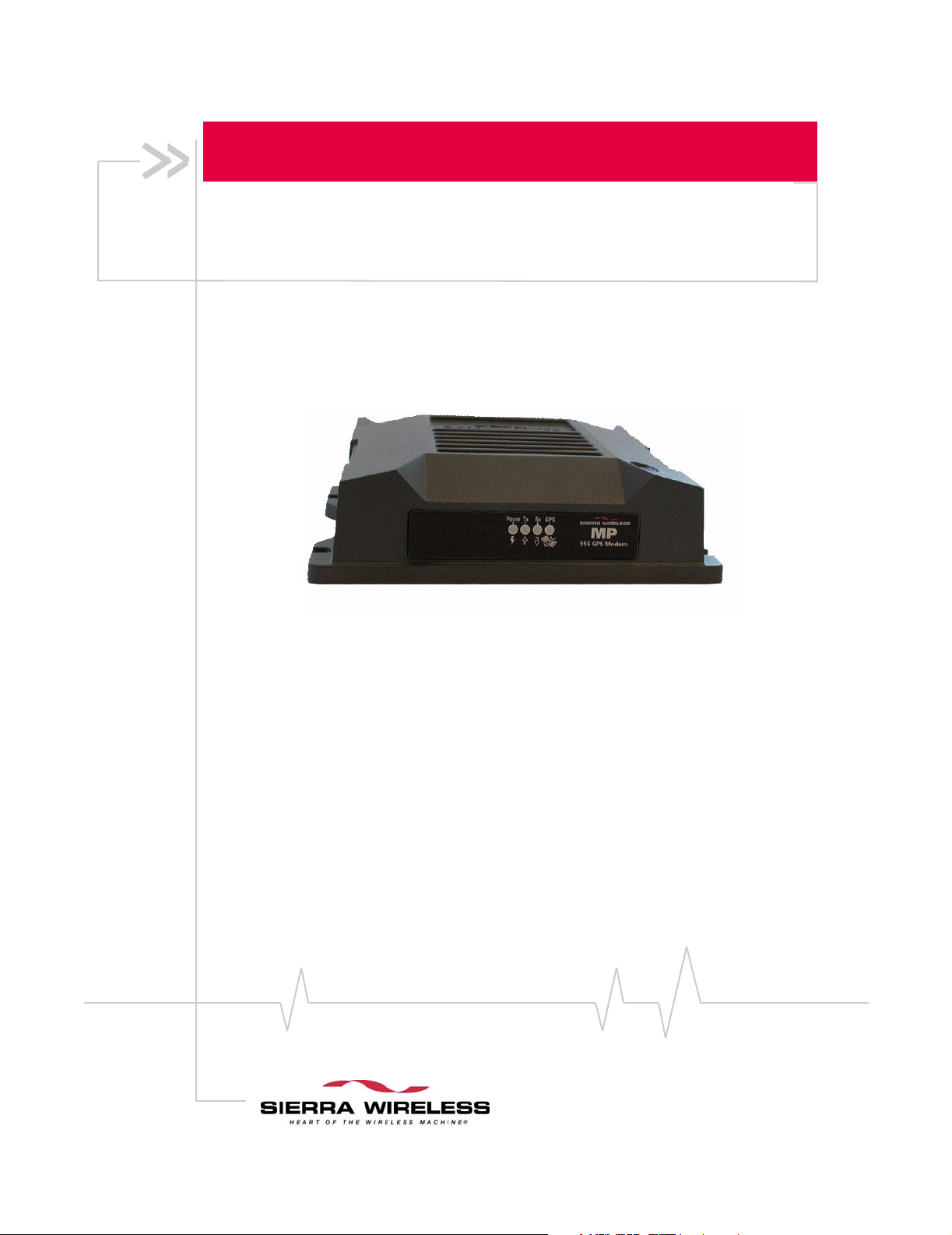
MP 555 GPS Rugged Wireless Modem
Vehicle Installation Guide
2130297
Rev 2.1
Page 2

Page 3

Preface
Important Notice
Due to the nature of wireless communications, transmission
and reception of data can never be guaranteed. Data may be
delayed, corrupted (i.e., have errors) or be totally lost.
Although significant delays or losses of data are rare when
wireless devices such as the Sierra Wireless modem are used in
a normal manner with a well-constructed network, the Sierra
Wireless modem should not be used in situations where
failure to transmit or receive data could result in damage of
any kind to the user or any other party, including but not
limited to personal injury, death, or loss of property. Sierra
Wireless, Inc., accepts no responsibility for damages of any
kind resulting from delays or errors in data transmitted or
received using the Sierra Wireless modem, or for failure of the
Sierra Wireless modem to transmit or receive such data.
If you have purchased this product under a United States
Government contract, it shall be subject to restrictions as set
forth in subparagraph (c) 1)(ii) of Defense Federal Acquisitions
Regulations (DFARs) Section 252.227-7013 for Department of
Defense contracts, and as set forth in Federal Acquisitions
Regulations (FARs) Section 52.227-19 for civilian agency
contracts or any successor regulations. If further government
regulations apply, it is your responsibility to ensure
compliance with such regulations.
(
Safety and Hazards Do not operate the Sierra Wireless modem in areas where
blasting is in progress, where explosive atmospheres may be
present, near medical equipment, near life support equipment,
or any equipment which may be susceptible to any form of
radio interference. In such areas, the Sierra Wireless modem
MUST BE POWERED OFF. The Sierra Wireless modem can
transmit signals that could interfere with this equipment.
Do not operate the Sierra Wireless modem in any aircraft,
whether the aircraft is on the ground or in flight. In aircraft, the
Sierra Wireless modem MUST BE POWERED OFF
operating, the Sierra Wireless modem can transmit signals that
could interfere with various onboard systems.
Note: Some airlines may permit the use of cellular phones while the
aircraft is on the ground and the door is open. Sierra Wreless
modems may be used at this time.
The driver or operator of any vehicle should not operate a
computer or any other device connected to the Sierra Wireless
modem while in control of a vehicle. Doing so will detract
. When
i
Rev 2.1 3
Jan.05
Page 4

MP 555 GPS Vehicle Installation Guide
Limitation of The information in this manual is subject to change without
Liability
from the driver or operator's control and operation of that
vehicle. In some states and provinces, operating such communications devices while in control of a vehicle is an offence.
notice and does not represent a commitment on the part of
Sierra Wireless, Inc. SIERRA WIRELESS, INC. AND ITS
AFFILIATES SPECIFICALLY DISCLAIM LIABILITY FOR
ANY AND ALL DIRECT, INDIRECT, SPECIAL, GENERAL,
INCIDENTAL, CONSEQUENTIAL, PUNITIVE OR
EXEMPLARY DAMAGES INCLUDING, BUT NOT LIMITED
TO, LOSS OF PROFITS OR REVENUE OR ANTICIPATED
PROFITS OR REVENUE ARISING OUT OF THE USE OR
INABILITY TO USE ANY SIERRA WIRELESS, INC.
PRODUCT, EVEN IF SIERRA WIRELESS, INC. AND/OR ITS
AFFILIATES HAS BEEN ADVISED OF THE POSSIBILITY OF
SUCH DAMAGES OR THEY ARE FORESEEABLE OR FOR
CLAIMS BY ANY THIRD PARTY.
Notwithstanding the foregoing, in no event shall Sierra
Wireless, Inc. and/or its affiliates aggregate liability arising
under or in connection with the Sierra Wireless, Inc. product,
regardless of the number of events, occurrences, or claims
giving rise to liability, be in excess of the price paid by the
purchaser for the Sierra Wireless, Inc. product.
Patents Portions of this product are covered by some or all of the
following US patents:
5,515,013 5,617,106 5,629,960 5,682,602 5,748,449
5,845,216 5,847,553 5,878,234 5,890,057 5,929,815
6,169,884 6,191,741 6,199,168 6,327,154 6,339,405
6,359,591 6,400,336 6,643,501 6,516,204 6,561,851
6,653,979 6,697,030 6,712,627, 6.785,830 D367,062
D372,248 D372,701 D416,857 D442,170 D452,495
D452,496 D453,733 D459,303 D496,642 D496,655
and other patents pending.
Manufactured or sold by Sierra Wireless or its licensees under
one or more patents licensed from InterDigital Group.
Licensed by QUALCOMM Incorporated under one or more of
the following United States Patents and/or their counterparts
in other nations:
2130297 4
Page 5

Preface
4,901,307 5,490,165 5,056,109 5,504,773
5,101,501 5,506,865 5,109,390 5,511,073
5,228,054 5,535,239 5,267,261 5,544,196
5,267,262 5,568,483 5,337,338 5,600,754
5,414,796 5,657,420 5,416,797 5,659,569
5,710,784 5,778,338
Copyright
© 2005 Sierra Wireless, Inc. All rights reserved.
Trademarks “Heart of the Wireless Machine” is a registered trademarks of
Sierra Wireless, Inc.
Sierra Wireless, the Sierra Wireless logo, the red wave design,
and Watcher are trademarks of Sierra Wireless, Inc.
Windows
CDMA2000
nications Industry Association (TIA-USA).
Other trademarks are the property of the respective owners.
®
is a registered trademark of Microsoft Corporation.
®
1X is a registered trademark of the Telecommu-
Contact
Information
Sales Desk: Phone: 1-604-232-1488
Hours: 8:00am to 5:00pm Pacific Time
e-mail: sales@sierrawireless.com
Post: Sierra Wireless, Inc.
13811 Wireless Way,
Richmond, BC
Canada V6V 3A4
Fax: 1-604-231-1109
Web: www.sierrawireless.com
Your comments and suggestions on improving this documentation are welcome and appreciated. Please e-mail your
feedback to
Consult our website for up-to-date product descriptions,
documentation, application notes, firmware upgrades, troubleshooting tips, and press releases:
documentation@sierrawireless.com. Thank you.
www.sierrawireless.com
Rev 2.1 5
Jan.05
Page 6

MP 555 GPS Vehicle Installation Guide
2130297 6
Page 7

Table of Contents
Introducing the MP 555 GPS modem . . . . . . . . . . . . . . . . . . . . . . . . . . . . . . . . . . .9
System Requirements . . . . . . . . . . . . . . . . . . . . . . . . . . . . . . . . . . . . . . . . . . 10
Supported Platforms
Package Contents . . . . . . . . . . . . . . . . . . . . . . . . . . . . . . . . . . . . . . . . . . . . . . . . . 11
Documentation . . . . . . . . . . . . . . . . . . . . . . . . . . . . . . . . . . . . . . . . . . . . . . . . 11
Modem Accessories . . . . . . . . . . . . . . . . . . . . . . . . . . . . . . . . . . . . . . . . . . . . 12
Warranty . . . . . . . . . . . . . . . . . . . . . . . . . . . . . . . . . . . . . . . . . . . . . . . . . . . . . . . . . 12
Installing the MP 555 GPS Modem in a Vehicle . . . . . . . . . . . . . . . . . . . . . . . .13
Installation Overview . . . . . . . . . . . . . . . . . . . . . . . . . . . . . . . . . . . . . . . . . . . . . . 13
GPS and I/O Options . . . . . . . . . . . . . . . . . . . . . . . . . . . . . . . . . . . . . . . . . . . 14
The Modem Housing . . . . . . . . . . . . . . . . . . . . . . . . . . . . . . . . . . . . . . . . . . . . . . 14
Connector Panel . . . . . . . . . . . . . . . . . . . . . . . . . . . . . . . . . . . . . . . . . . . . . . . 15
Indicator Panel . . . . . . . . . . . . . . . . . . . . . . . . . . . . . . . . . . . . . . . . . . . . . . . . 15
Reset Button . . . . . . . . . . . . . . . . . . . . . . . . . . . . . . . . . . . . . . . . . . . . . . . . . . 15
Required Equipment. . . . . . . . . . . . . . . . . . . . . . . . . . . . . . . . . . . . . . . . . . . . . . . 16
Mounting the Modem . . . . . . . . . . . . . . . . . . . . . . . . . . . . . . . . . . . . . . . . . . . . . . 16
Selecting a Mounting Location
. . . . . . . . . . . . . . . . . . . . . . . . . . . . . . . . . . . . . . . . . . . 10
. . . . . . . . . . . . . . . . . . . . . . . . . . . . . . . . . . 16
Mounting Procedure
Grounding the Modem . . . . . . . . . . . . . . . . . . . . . . . . . . . . . . . . . . . . . . . . . . . . . 18
Antennas . . . . . . . . . . . . . . . . . . . . . . . . . . . . . . . . . . . . . . . . . . . . . . . . . . . . . . . . 19
CDMA RF Antennas . . . . . . . . . . . . . . . . . . . . . . . . . . . . . . . . . . . . . . . . . . . . 19
GPS Antennas . . . . . . . . . . . . . . . . . . . . . . . . . . . . . . . . . . . . . . . . . . . . . . . . . 19
Antenna Locations . . . . . . . . . . . . . . . . . . . . . . . . . . . . . . . . . . . . . . . . . . . . . 20
Installing Antennas
Rev 2.1 7
Jan.05
. . . . . . . . . . . . . . . . . . . . . . . . . . . . . . . . . . . . . . . . . . . 17
. . . . . . . . . . . . . . . . . . . . . . . . . . . . . . . . . . . . . . . . . . . . 20
Page 8

MP 555 GPS Vehicle Installation Guide
Power Wiring . . . . . . . . . . . . . . . . . . . . . . . . . . . . . . . . . . . . . . . . . . . . . . . . . . . . . 20
The Power Connector
. . . . . . . . . . . . . . . . . . . . . . . . . . . . . . . . . . . . . . . . . . 20
Power connector (Molex) pinouts. . . . . . . . . . . . . . . . . . . . . . . . . . . . . . 21
Ignition Sense On/Off Wiring . . . . . . . . . . . . . . . . . . . . . . . . . . . . . . . . . . . . 21
Ignition sense options . . . . . . . . . . . . . . . . . . . . . . . . . . . . . . . . . . . . . . . 22
Power Harness Grounding
Making Proper Power Connections
. . . . . . . . . . . . . . . . . . . . . . . . . . . . . . . . . . . . . . 22
. . . . . . . . . . . . . . . . . . . . . . . . . . . . . . 23
Correct wire splicing. . . . . . . . . . . . . . . . . . . . . . . . . . . . . . . . . . . . . . . . . 23
Using crimp terminals . . . . . . . . . . . . . . . . . . . . . . . . . . . . . . . . . . . . . . . 23
Powering On the Modem
. . . . . . . . . . . . . . . . . . . . . . . . . . . . . . . . . . . . . . . 23
Data Wiring . . . . . . . . . . . . . . . . . . . . . . . . . . . . . . . . . . . . . . . . . . . . . . . . . . . . . . 23
Cable Connection to the Computer . . . . . . . . . . . . . . . . . . . . . . . . . . . . . . . 24
Serial connector (DB9) pinouts. . . . . . . . . . . . . . . . . . . . . . . . . . . . . . . . 24
Connecting the serial or USB cable . . . . . . . . . . . . . . . . . . . . . . . . . . . . 25
I/O Port Connections . . . . . . . . . . . . . . . . . . . . . . . . . . . . . . . . . . . . . . . . . . . 25
Panic button connections . . . . . . . . . . . . . . . . . . . . . . . . . . . . . . . . . . . . 25
Analog sensor connections . . . . . . . . . . . . . . . . . . . . . . . . . . . . . . . . . . . 25
Completing the Installation . . . . . . . . . . . . . . . . . . . . . . . . . . . . . . . . . . . . . . . . . 26
Technical Specifications . . . . . . . . . . . . . . . . . . . . . . . . . . . . . . . . . . . . . . . . . . . .27
Indicator Operation. . . . . . . . . . . . . . . . . . . . . . . . . . . . . . . . . . . . . . . . . . . . . . . . 27
RF and Electrical Specifications . . . . . . . . . . . . . . . . . . . . . . . . . . . . . . . . . . . . . 28
Environmental Specifications . . . . . . . . . . . . . . . . . . . . . . . . . . . . . . . . . . . . . . . 29
Weight and Dimensions. . . . . . . . . . . . . . . . . . . . . . . . . . . . . . . . . . . . . . . . . . . . 29
GPS Performance
. . . . . . . . . . . . . . . . . . . . . . . . . . . . . . . . . . . . . . . . . . . . . . . . 30
I/O Port Characteristics . . . . . . . . . . . . . . . . . . . . . . . . . . . . . . . . . . . . . . . . . . . . 30
Regulatory Information . . . . . . . . . . . . . . . . . . . . . . . . . . . . . . . . . . . . . . . . . . . . . .31
Industry Canada Approval . . . . . . . . . . . . . . . . . . . . . . . . . . . . . . . . . . . . . . . . . . 31
FCC Approval (U.S.A.) . . . . . . . . . . . . . . . . . . . . . . . . . . . . . . . . . . . . . . . . . . . . . 31
8
2130297
Page 9

1: Introducing the
MP 555 GPS modem
•
Package Contents
•
Warranty
The Sierra Wireless MP 555 GPS modem provides a wireless
network connection for portable computers installed in
vehicles. The modem has a rugged design that allows it to
withstand the vibration, shock, humidity, and extremes of
temperature experienced in the normal operation of police,
emergency, utility, and field service vehicles.
The network connection provided by the MP 555 GPS can be
used to access shared data, browse the Internet, and send and
receive e-mail and text messages. The modem also allows for
sensors, gauges, and alarms (such as panic buttons) to be
deployed in vehicles and remotely monitored from a central
location or dispatch. A built-in GPS module provides location
and heading data that can also be remotely monitored.
1
Rev 2.1 Jan.05 9
Page 10
MP 555 GPS Vehicle Installation Guide
System Requirements
Note: Do not connect the
MP 555 GPS to a USB port on a
PC before installing the software.
Software installation instructions
are provided in the Software
Installation, Conf guration, and
Integration Guide (document
number 2130346) on the installation CD.
i
Supported Platforms
The MP 555 GPS wireless modem connects to a personal
computer with either a serial cable or USB cable. Your
computer must therefore have either an available serial port or
USB port and an appropriate cable.
The Watcher software supports notebook computers with
these operating systems (using either a serial or USB PC
connection):
Windows 2000 Professional (with Service Pack 4 or later)
•
Windows XP Professional
•
These operating systems are also supported but require a serial
connection between the modem and PC:
• Microsoft
•
Windows NT 4.0 (with Service Pack 6a)
For detailed system requirements, see the MP 555 GPS Software
Installation, Configuration, and Integration Guide
® ®
Windows 98 SE
.
10
2130297
Page 11

Introducing the MP 555 GPS modem
Package Contents
Each MP 555 GPS box contains:
•
The MP 555 GPS modem
•
A mounting template
•
Mounting screws and washers
•
An installation and documentation CD
•
A power harness
If any of these materials are missing, please contact your
account manager at your reseller or at Sierra Wireless to obtain
them.
Documentation
The MP 555 GPS documentation consists of two guides and an
online help system.
The
MP 555 GPS Modem Vehicle Installation Guide (this
document) provides instructions on installing the hardware,
describing how to:
•
Mount the modem in a vehicle.
•
Connect to the vehicle’s battery.
•
Connect to the vehicle’s ignition switch or a separate on/
off switch.
•
Ground the device.
•
Connect the radio and GPS antennas.
•
Connect a notebook computer, and other I/O (input/
output) devices.
The
MP 555 GPS Software Installation, Configuration, and
Integration Guide describes how to:
•
Install the software.
•
Configure the software to use a CDMA account.
•
Understand the LEDs on the modem and the indicators in
the Watcher software.
•
Set up the modem’s operating mode and configure the
feature that allows for CSD connections.
• /
Configure the modem to report GPS and or I/O (input/
output) data (from sensors, gauges, or panic buttons).
•
Use the modem to connect to a VPN (Virtual Private
Network).
•
Collect and use GPS and I/O data from a fleet of vehicles in
which MP 555 GPS modems are installed.
Rev 2.1 11
Jan.05
Page 12

MP 555 GPS Vehicle Installation Guide
Software Installation, Configuration, and Integration Guide
The
and the
Document Format files on the installation CD.
Online help is provided with Watcher. The help describes all
the icons and indicators in Watcher, provides detailed instructions on using Watcher to make data connections, and explains
how to send and receive SMS messages. When using Watcher,
you can access help through the menu system or by pressing
the
Vehicle Installation Guide are provided as PDF (Portable
)
<F1> key.
Modem Accessories
For information about accessories for the MP 555 GPS wireless
modem—including cables and antennas—contact your
account manager at your reseller or at Sierra Wireless.
Warranty
Sierra Wireless, Inc. warrants the MP 555 GPS modem against
all defects in materials and workmanship for a period of three
(3) years from the date of purchase.
The sole responsibility of Sierra Wireless, Inc. under this
warranty is limited to either repair or, at the option of Sierra
Wireless, Inc., replacement of the radio modem. There are no
expressed or implied warranties, including those of fitness for
a particular purpose or merchantability, which extend beyond
the face hereof.
Sierra Wireless, Inc. is not liable for any incidental or consequential damages arising from the use, misuse, or installation
of the MP 555 GPS modem.
This warranty does not apply if the serial number label has
been removed, or if the wireless modem has been subjected to
physical abuse, improper installation, or modification.
12
2130297
Page 13

2: Installing the MP 555 GPS
Modem in a Vehicle
•
Installation Overview
•
The Modem Housing
•
Required Equipment
•
Mounting the Modem
•
Grounding the Modem
•
Antennas
•
Power Wiring
•
Data Wiring
•
Completing the
Installation
Note: The MP 555 GPS is
designed for negative-ground
vehicles only. It will not function
in a positive-ground vehicle.
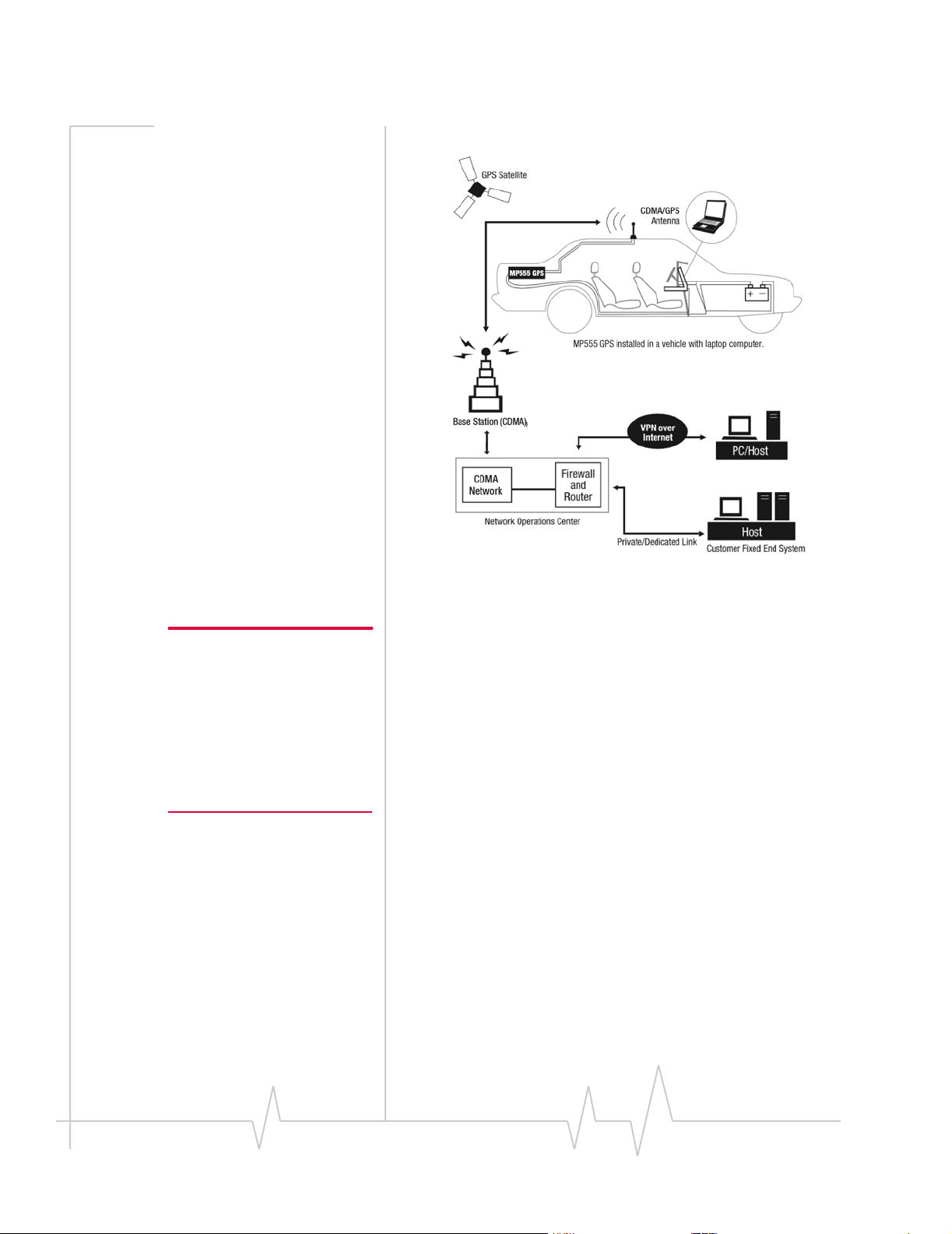
Figure 2-1: Basic diagram for the installation of the MP 555 GPS in a vehicle
equipped with a notebook PC and a combination antenna, using the car
battery for power and ignition-sense w ng for power on/off.
iri
Installation Overview
2
Note: All electrica nstallations
are potent ally dangerous, and
should be performed by
personnel with thorough training
in safe electrical w ring procedures for vehicles.
i
l i
i
The installation process for the MP 555 GPS varies depending
on how you plan to use it, where it best fits in your vehicle,
and which of its features you plan to use. In all cases, however,
you must:
Mount the modem (“Mounting the Modem” on page 16
1. )
Mount the CDMA RF Radio Frequency antenna and
2. ( )
connect the antenna cable (“Antennas” on page 19)
Install the power harness (“Power Wiring” on page 20)
3.
Install the serial or USB cable for the PC. (This should not
4.
be connected to the PC until the software is installed. See
“Cable Connection to the Computer” on page 24)
Rev 2.1 Jan.05 13
Page 14

MP 555 GPS Vehicle Installation Guide
GPS and I/O Options
The MP 555 GPS wireless modem provides support for GPS
(Global Positioning System) and for attaching input/output
devices.
GPS. If you plan to use the MP 555 GPS’s built-in GPS module,
you must connect a GPS antenna and an antenna cable, or use
a combination antenna that can connect to both the GPS and
CDMA RF connectors on the MP 555 GPS housing.
Other I O devices. Other devices, such as panic buttons,
sensors, or gauges may also be installed with the MP 555 GPS
and connected with an I/O cable to the I/O port. (See “I/O Port
Connections” on page 25.)
/
The Modem Housing
The MP 555 GPS has a rectangular metal housing:
Figure 2-2: Top view of the MP 555 GPS.
There is a connector panel on one end of the housing, an
indicator panel on the opposite end, a reset button on top, and
mounting holes along the bottom edges on either side.
As shown in the following photographs, the modem has seven
connectors on its connector panel, six of which are currently
supported. The indicator panel has four indicator LEDs.
14
2130297
Page 15

Installing the MP 555 GPS Modem in a Vehicle
Connector Panel
The MP 555 GPS modem’s connector panel has these ports:
RS232 serial
(female DB9)
Figure 2-3: The connector panel of the MP 555 GPS modem.
USB
GPS antenna
(female SMA)
CDMA
RF antenna
(femal
e TNC)
I/O connector
(female DB15)
Power harness
(Mol
ex connector)
Ground screw
Indicator Panel
The MP 555 GPS’s indicator panel includes four indicator
lights:
Power
Transmit (Tx)
Figure 2-4: The indicator panel of the MP 555 GPS modem.
Receive (Rx)
GPS
Reset Button
The reset button for the MP 555 GPS
is on the top of the housing. Hold it
down for at least 2 seconds with a
pen or screwdriver to perform a
hard reset of the modem, which
includes a self-test sequence.
Figure 2-5: The modem reset button.
Rev 2.1 15
Jan.05
Page 16

MP 555 GPS Vehicle Installation Guide
Required Equipment
To install the MP 555 GPS, you require the modem, the
provided power harness (or existing MP200 Series power
harness) and mounting template, and the screws and washers
that come with the device. You also require:
USB or 9-pin serial cable This must be long enough to
• A
run from the mounting location of the MP 555 GPS to the
computer. The maximum length for the serial or USB cable
is 5.5 m (18 feet). The USB cable must have a Type A male
connector at the PC end and a Type B male connector at
the modem end.
Note: If GPS is being implemented, you requre ether two
antennas or a combination
CDMA and GPS antenna.
Note: The MP 555 GPS modem,
your computer, and any other
devices should be powered off
while you are connecting cables.
i i
• A The antenna must
CDMA IS-95 RF antenna and cable
have the appropriate regulatory approval, 50 ohm
impedance, and a male TNC connector. This may be a
hard-mount or magnetic-mount antenna—see “Antennas”
on page 19)
GPS antenna and cable optional)—This is necessary if
• A (
you plan to use the built-in GPS module. (See “Antennas”
on page 19.)
power supply. This is usually the vehicle’s battery.
• A
Appropriate electrical grounding. If a ground wire is
•
necessary, use a 16-gauge wire and connect it to the
ground screw on the modem’s connector panel.
• An ).
I/O cable (optional This is required if a panic button,
sensor, gauge, or other I/O device is being installed. (See
“I/O Port Connections” on page 25.)
(
Mounting the Modem
The MP 555 GPS can be mounted in the trunk of the vehicle,
under the dashboard, or under a front or rear seat.
Selecting a Mounting Location
16
When selecting a mounting location, consider the following
factors:
•
The modem should not be exposed to weather and
environmental conditions beyond the ranges listed in the
technical specifications on page 29. Avoid excessive heat
from the engine compartment, heaters, or the exhaust
system, and extreme cold from direct contact with air
conditioners or other cooling systems. Never immerse the
modem in water or any other liquid.
2130297
Page 17

Installing the MP 555 GPS Modem in a Vehicle
• If you are replacing an MP200 modem, the MP 555 GPS is
smaller, but can be mounted in the same location using
the existing mounting holes. The MP200 has six mounting
holes, and any four adjacent ones will line up with those
on the MP 555 GPS.
• Every device connected to the MP 555 GPS, as well as the
modem itself, should be grounded as appropriate for the
installation. (See “Grounding the Modem” on page 18 and
“Power Harness Grounding” on page 22.)
• Wiring and connections should be as simple as possible.
Cables for power, antennas, the computer, and any I/O
devices must be routed to their destinations without using
excess wiring.
• All connectors and the reset button should be easy to reach
and the indicator lights should be visible.
Mounting Procedure
To mount the MP 555 GPS:
1. Use the provided mounting template to mark the location
of the mounting holes.
2. Drill the required 5/32" pilot holes (unless you are reusing
holes from an MP200 modem mounting—see page 16).
3. Use the supplied mounting screws and washers to secure
the MP 555 GPS through the holes along the edge of the
case bottom.
Figure 2-6: The bottom of the MP 555 GPS housing. Arrows indicate the
mounting holes.
Rev 2.1 Jan.05 17
Page 18

MP 555 GPS Vehicle Installation Guide
Grounding the Modem
Note: Failing to prov
dedicated ground for each
piece of electrical equipment
can damage the equipment.
Note: If you are replacing an
MP200 modem, you can use the
MP200 power harness rather
than install ng the MP 555 GPS
power harness. The only
difference between the
harnesses is that the MP200
harness has a fused ground wire
whil
has an unfused ground wire.
i
e the MP 555 GPS harness
ide a
It is standard practice in automotive installations to provide a
good quality ground for each piece of electrical equipment. In
most cases, the modem should be grounded by connecting the
black ground wire of the power harness either to the vehicle
chassis or to the negative terminal of the battery.
If other devices connected to the modem (such as a notebook
computer) are not properly grounded, there is some risk that
the other device will ground itself through the cable
connecting it to the modem. This creates a hazardous situation
and could cause equipment damage. If you cannot properly
ground these devices, a potential solution is to install a fuse in
the ground return wire.
The power harness for the MP 555 GPS modem has 5 A fuses
on the red power wire and the white ignition sense wire, but
on the black ground return wire. (See “Power Wiring” on
not
page 20.)
Ground screw
Figure 2-7: The ground screw connector (bottom) on the connector panel.
To facilitate other ground schemes, a ground screw is
provided on the connector panel of the MP 555 GPS. Use of
this ground screw is not required as long as the power harness
is properly grounded. (Use a 16-gauge wire if you choose to
use the ground screw.
Note: All electrica nstallations are potentially dangerous, and should
be performed by personnel with thorough training n safe e
wiring procedures for veh
)
l i
i lectrical
icles.
18
2130297
Page 19

Installing the MP 555 GPS Modem in a Vehicle
Note: Tighten cables connected Antennas to the MP 555 GPS by hand. Do not use tools.
SMA
TNC
CDMA RF Antennas
The MP 555 GPS requires an approved CDMA RF (Radio
Frequency) antenna. The antenna must have 50 ohms
impedance and a cable with a male TNC connector, as well as
the following characteristics:
• The total maximum gain, including the cable loss, must
not exceed 5.2 dBi (if the antenna operates on the PCS
band) or 6 dBi (if the antenna operates only on the Cellular
band).
• The antenna must transmit and receive on the necessary
frequency bands in your coverage area. The MP 555 GPS
supports these RF bands:
· 1900 MHz (PCS)
· 800 MHz (Cellular)
A dual-band antenna that supports both frequencies can be
used. If your MP 555 GPS will only be connected to networks that use one of the bands, an appropriate singleband antenna is sufficient. Contact your service provider
for information about radio bands used in your area.
Figure 2-8: The MP 555 GPS’s SMA connector
for the GPS antenna, and the TNC connector
for the CDMA RF antenna.
The MP 555 GPS requires a CDMA
RF antenna to connect to the CDMA
wireless network. If the built-in GPS
module is used, it requires a
dedicated GPS antenna, or a combination antenna with cables for both
antenna connectors on the modem.
For more information about antennas for your installation,
contact your account manager at your reseller or at Sierra
Wireless.
GPS Antennas
If you are installing a GPS antenna, it connects to the
MP 555 GPS modem using a male SMA connector. Contact
your account manager at your reseller or at Sierra Wireless for
more information about compatible GPS antennas.
Rev 2.1 Jan.05 19
Page 20

MP 555 GPS Vehicle Installation Guide
Antenna Locations
When selecting locations for the GSM CDMA RF and GPS
antennas:
Refer to the documentation provided with each antenna to
•
determine whether it requires a ground plane.
Ensure that the CDMA RF antenna is mounted at least
•
20 cm (8 inches) from vehicle occupants and bystanders.
Ensure that all radio antennas (CDMA RF, GPS, CB radio,
•
car radio) are separated as much as possible from each
other. Antennas should never be mounted less than 30 cm
(1 foot) apart.
Installing Antennas
To install the CDMA RF and GPS antennas:
Mount each antenna according to the instructions
1.
provided with it.
Thread the antenna cables through the car to reach the
2.
modem. Secure the cables as necessary.
Connect the cables to the MP 555 GPS by attaching the
3.
cable into the modem’s TNC (for the CDMA RF antenna)
or SMA connector (for the GPS antenna). Hand-tighten the
connectors; do not use tools.
Note: To avoid RF nterference
problems and possible damage
to the MP 555 GPS, do not
power on the modem before
connecting the CDMA IS-95 RF
antenna.
i
Power Wiring
In a typical installation, the MP 555 GPS is connected to the
vehicle’s battery with the supplied power harness (or if an
MP200 modem was previously installed, with the MP200
power harness). The MP 555 GPS supports a voltage range
between 9 VDC and 36 VDC, and is designed for both 12 VDC
and a 24 VDC vehicle electrical systems.
Note: All electrica nstallations are potentially dangerous, and should
be performed by personne with thorough training n safe e
wiring procedures for veh
The Power Connector
The power harness (Sierra Wireless part number 2000154)
connects to the MP 555 GPS with a Molex connector (part
number 39-01-2040 or 39-01-2045). The part number for the
pins is 39-00-0039.
l i
l i lectrical
icles.
20
2130297
Page 21

Installing the MP 555 GPS Modem in a Vehicle
Power connector (Molex) pinouts
The pinouts for the Molex connector on the power harness are
as follows:
Note: If you are install ng an
MP 555 GPS in a vehicle in
which an MP200 was previously
installed, you can use the
MP200 power harness that is
already installed. The only
difference between the
harnesses is that the MP200
harness has a fused ground wire
e the MP 555 GPS harness
whil
has an unfused ground wire.
Note: Do not install an on/off
switch on the main (red) battery
line, or connect the white ign
sense wire to the red battery
wire. Both configurat ons bypass
the modem's controlled
shutdown sequence, and may
cause data loss and subsequent
power-on problems. Incorrect
wiring may also completely drain
the vehicle battery.
i
ition
i
White wire
(Ignition sense)
(Unused)
Red wire
(Battery)
Black wire
(Ground)
Figure 2-9: Pinouts for the power harness.
The battery (red and ignition sense (white) wires in the power
)
harness include 5 A fuses. The black ground wire is not fused.
(See “Power Harness Grounding” on page 22.) Replacement
power harnesses are available from Sierra Wireless.
Ignition Sense On/Off Wiring
The modem’s power on/off is controlled by the ignition sense
line (white wire) using internal software, rather than a hard
on/off switch on the red power line. The red, black, and white
wires connect to the battery and ignition switch as shown in
the power harness wiring diagram.
Switch (vehicle
i
gnition key, or
separate)
ire
Red w
(Battery)
5 A fuses (on red
and white only)
MP
White wire
(Ignition sense)
Vehi
cle battery
Figure 2-10: Wirng for the power harness. The white wire is ignition sense.
•
When the white ignition sense line is pulled high (5 to
i
Black unfused wire
(Ground)
36 V), the modem will power on.
•
When the ignition sense line is pulled low (less than 2 V),
the modem performs a controlled shutdown sequence
Rev 2.1 21
Jan.05
Page 22

MP 555 GPS Vehicle Installation Guide
(under software control), de-registering and saving any
relevant operational data before powering off.
Ignition sense options
There are three ways to connect the ignition sense wiring:
•
Engine on only. The white ignition sense wire can be
connected to the vehicle’s ignition switch so that the
MP 555 GPS is powered on only when the ignition key is
switched to the full “On” position, i.e. when the engine has
been started. In this configuration, the engine must be
running for the modem to be on.
—or—
Accessory on. The white ignition sense wire can be
•
connected to the vehicle’s ignition switch so that the
MP 555 GPS is powered on when the ignition is switched
to “Accessory” mode. In this configuration, the modem is
whenever other vehicle electrical devices can be switched
on
—such as when the radio and windshield fan can run.
on
—or—
Note: If you choose to install a
separate switch, it must still be
connected to the white gnition
sense wire, not the red battery
wire, so that the modem can
perform a controlled shutdown,
as described on page 21.
i
•
Separately switched. The white ignition sense wire can be
connected to a separate switch, mounted under the
dashboard or in another convenient location, which allows
the MP 555 GPS to be turned on or off regardless of the
position of the ignition key. In this configuration, the
modem can be powered on or off even if the key is not in the
ignition.
The modem also has a “Power Off Timer”. When power is
removed from the ignition sense wire, the modem remains on
for the period defined by the Power Off Timer. The maximum
(
duration is four hours.) The Power Off Timer is configured in
Watcher. See the online help for details.
Power Harness Grounding
The black ground wire from the power harness must be
connected to the grounded negative terminal of the vehicle
battery, or another appropriate electrical ground if you are
using an alternate power source. Failing to ground the power
harness properly may damage the MP 555 GPS, may cause
radio interference, and can be dangerous. (See “Grounding the
Modem” on page 18.
The ground wire in the MP 555 GPS power harness is not
fused.
)
22
2130297
Page 23

Installing the MP 555 GPS Modem in a Vehicle
Making Proper Power Connections
Connecting the MP 555 GPS’s power wires properly is
important—poor connections can damage the wiring, the
modem, or the vehicle’s electrical system, and can also be
dangerous.
Note: Ensure that all wires are
correctly spliced or crimped.
Improper grounding and wire
connections may lead to
equipment damage or safety
hazards.
Correct wire splicing
The wires of the power harness may be spliced to the car
wiring. Proper splicing is essential to reliable operation of the
MP 555 GPS. Do NOT use “quick taps”; they reduce the
integrity of the wire that is cut and let moisture into the cable.
An appropriate method of splicing is to strip a small portion of
the insulation, solder the wires together, then heat-shrink the
connection to re-insulate it.
Using crimp terminals
If suitable terminal connection points are available on the
vehicle for power and ignition sense, then using automotive
crimp terminals is recommended. When using crimp
terminals, do not leave bare wire exposed. Do not use a crimp
terminal for more than one wire unless it is designed for that
purpose.
Powering On the Modem
Once the MP 555 GPS modem is powered on, the Power and
GPS indicators on the indicator panel should light, either
solid-on or flashing.
Data Wiring
The MP 555 GPS modem connects to:
A computer through the DB9 serial or USB connector.
•
Other optional devices through the DB15 I/O connector.
•
Rev 2.1 23
Jan.05
Page 24

MP 555 GPS Vehicle Installation Guide
Cable Connection to the Computer
Note: Do not connect the
MP 555 GPS to a USB port on a
PC before installing the software.
Software installation instructions
are provided in the Software
Installation, Conf guration, and
Integration Guide (document
number 2130352) on the installation CD.
i
The MP 555 GPS connects to a PC using a standard serial cable
(with a DB9 connector on the modem end) or USB cable (with
a Type A connector on the PC end an a Type B connector on
the modem end). The maximum length for the serial or USB
cable is 5.5 m (18 feet). These cables are readily available from
many suppliers.
Sierra Wireless sells suitable serial cables in 5 m (16-foot) (part
number 6000083) and 3 m (10-foot) (part number 6000048)
lengths.
Serial connector (DB9) pinouts
The MP 555 GPS is configured as DCE (Data Communications
Equipment) and uses the standard RS232 pin designations:
DB9 MALE
1. Data Carrier Detect (DCD)
2. Received Data (RXD)
3. Transmitted Data (TXD)
4. Data Terminal Ready (DTR)
5. Signal Ground (GND)
6. Data Set Ready (DSR)
7. Clear To Send (CTS)
8. Request To Send (RTS)
9. Ring Indicator (RI)
Figure 2-11: Pinouts for a RS232 male DB9 serial cable (left) that connects to
the MP 555 GPS’s female DB9 serial connector (right). Note that the two
figures’ pi
nouts are mirror images of one another, since they plug together.
24
The serial connector uses these voltage specifications:
Figure 2-12: Voltage specifications for the MP 555 GPS’s seral connector.
i
2130297
Page 25

Installing the MP 555 GPS Modem in a Vehicle
Connecting the serial or USB cable
Note: The MP 555 GPS and To install the serial or USB cable, thread the cable through the
your computer should be
powered off while connecting
cables.
vehicle and attach it to the DB9 or USB connector on the
modem. Attach the other end to the computer, and secure the
cable as necessary.
I/O Port Connections
The MP 555 GPS’s I/O port is a standard female DB15
connector.
I/O connector (DB15) pinouts
DB15 MALE
1.
Reserved—do not connect
2.
Reserved—do not connect
3. Digital I/O 1 (DIN1)
4. Digital input 3 (DIN3)
5.
Reserved for future support
of differential GPS—do not
connect
6.
Reserved for future support
of differential GPS—do not
connect
7. Analog input 2 (AIN2)
Figure 2-13: Pinouts for a male DB15 I/O cable (left) that connects to the
MP 555 GPS’s female DB15 I/O connector (right). Note that the two figures’
pinouts are mirror images of one another, since they plug together.
8. Analog input 4 (AIN4)
9.
Reserved—do not connect
10. Ground (GND)
11. Digital I/O 2 (DIN2)
12. Digital input 4 (DIN4)
13.
Reserved—do not connect
14. Analog input 1 (AIN1)
15. Analog input 3 (AIN3)
If you plan to use the I/O cable, you must construct or obtain
an I/O cable with a male DB15 connector to attach to the
modem. For more details on I/O connections, see the
MP 555 GPS Software Installation, Configuration, and Integration
Guide (document number 2130352) on the installation CD.
Panic button connections
An I/O cable for a panic button requires a wire to one of the
digital input or I/O pins (such as #3) and one wire to the
Ground pin (#10).
Analog sensor connections
An I/O cable for an analog sensor requires a wire to one of the
analog input pins (such as #7) and one wire to the Ground pin
(#10).
Rev 2.1 Jan.05 25
Page 26

MP 555 GPS Vehicle Installation Guide
Completing the Installation
Once you have mounted the MP 555 GPS and connected all the
appropriate cables and antennas, you can power on the
computer and the modem.
When you install and configure the supplied software from the
included CD (as described in the MP 555 GPS Software Instal-
lation, Configuration, and Integration Guide), you can then test
whether the modem is able to connect to and transmit data
over the CDMA network, and (if you have connected a GPS
antenna) whether the MP 555 GPS can determine its position.
26
2130297
Page 27

3: Technical Specifications
•
Indicator Operation
•
RF and Electrical
Specifications
•
Environmental
Specifications
Weight and
•
Dimensions
GPS Performance
•
I/O Port
•
Characteristics
This chapter describes the operation of the lights on the
indicator panel and provides technical data for the
MP 555 GPS modem.
Indicator Operation
There are four green LEDs (Light Emitting Diodes) on the front
panel of the MP 555 GPS. When the MP 555 GPS is first
powered (and when the modem is reset), all four LEDs should
flash briefly. The table below shows the behavior of the LEDs
during modem operation.
3
Table 3-1: LED operation
LED Indicates
Power
Tx
Rx
GPS
Behavior
Off Modem is not powered.
Rapid flashing Modem is powered and has not acquired
CDMA IS-95 or CDMA2000 1X service.
Slow flashing (about 1.5 seconds
between flashes)
On solid
Flashing Modem is transmitting data.
Flashing Modem is receiving data.
Off GPS module is not active.
Flashing GPS module s active but not recei v ng valid
Solid GPS module s active and providing val d fixes.
Modem has acquired CDMA IS-95 service but
not CDMA2000 1X service.
Modem has acquired CDMA2000 1X service.
fixes.
i i
i i
Rev 2.1 Jan.05 27
Page 28

MP 555 GPS Vehicle Installation Guide
RF and Electrical Specifications
Table 3-2: Radio frequency & electrical
specifications
Approvals FCC
Industry Canada
Compliance Compliant with:
IS-95A, IS-98D, IS-707A,
IS707A-1, CDMA Developers Group
Voltage Range 9 - 36 VDC
Current Max transmit (23 dBm output)
Cellular:
400 mA
PCS:
450 mA
Typical transmit
300 mA average
Receive:
240 mA
Idle (Ignition Sense off):
2 mA
a
Maximum Output
Power
Transmit PCS:
Receive PCS:
Channel spacing 1.25 MHz
Frequency
stability
a. i
This applies to a typ cal installation with a well-matched antenna.
All current values are measured with an input voltage of 12 V.
23 dBm (200 mW)
1850 to 1910 MHz
Cellular:
824 to 849 MHz
1930 to 1990 MHz
Cellular:
869 to 894 MHz
±150 Hz
28
2130297
Page 29

Technical Specifications
Environmental Specifications
Table 3-3: Environmental specifications
Operating
temperature
Stora g e
temperature
Humidity 95% RH non-condensing
Vibra t i o n SAE J1455 4.9
Shock SAE J1455 4.10.3.2 and 4.10.3.4
ESD +/- 15 kV air discharge
-30 to +70 °C
(-22 to +158 °F)
-40 to +85 °C
(-40 to +185 °F)
SAE J1455 4.2
MIL 202G 103B and 106G
MIL 810F 507.4
MIL 202G 214
MIL 810F 514.5
MIL 202G 213B
MIL 810F 516.5
as per IEC 61000-4-2
Weight and Dimensions
Table 3-4: Weight and dimensions
Weight 0.9 kg (2 lbs)
Height 49 mm (1.93 in)
Width 138 mm (5.43 in)
Length 176 mm (6.93 in)
Rev 2.1 Jan.05 29
Page 30

MP 555 GPS Vehicle Installation Guide
GPS Performance
Table 3-5: GPS performance
Accuracy Horizontal:
< 6 m (50%), < 9 m (90%)
Altitude:
< 11 m (50%), < 18 m (90%)
Velocity:
0.06 m/sec
Acquisition times Re-acquisition
Operational limits Altitude:
< 2 sec (90%)
Hot start:
< 14 sec (50%), < 18 sec (90%)
Warm start:
< 38 sec (50%), < 45 sec (90%)
Cold start:
< 90 sec (50%), < 170 sec (90%)
< 18,000 m or velocity < 515 m/sec
(either limit may be exceeded but not both)
I/O Port Characteristics
Table 3-6: I/O port characteristics
Absolute max -0.3 VDC to 36 VDC
voltage
Digital inputs Open-collector, max current 500 mA
Vih, min 2 VDC
Vil, max 0.8 VDC
Vih, max 36 VDC
Digital outputs Open-collector
Analog input Zero-scale: 0 VDC
Full-scale: 3.3 VDC
Leakage current: 66 µA
2130297 30
Page 31

4: Regulatory Information
•
Industry Canada
Approval
•
FCC Approval (U.S.A.)
Industry Canada Approval
4
Note: Unauthorized mod fications or changes not expressly
approved by Sierra W reless,
Inc. could void compliance with
regulatory rules, and thereby
your authority to use this
equipment.
i
i
To ensure that the MP 555 GPS modem meets the Health
Canada’s Safety Code 6 requirements, a separation distance of
at least 20 cm must be maintained between the modem’s
CDMA antenna and the body of the user and any nearby
persons at all times and in all applications and uses.
Additionally, the maximum antenna gain in the PCS band,
including cable loss, must not exceed 5.2 dBi, and in the
Cellular band, must not exceed 6 dBi, to comply with Industry
Canada and Health Canada regulations limiting both
maximum RF output power and human exposure to RF
radiation.
FCC Approval (U.S.A.)
To comply with FCC regulations limiting both maximum RF
output power and human exposure to RF radiation, the
maximum antenna gain, including cable loss, in the PCS band,
must not exceed 5.2 dBi, and in the Cellular band, must not
exceed 6 dBi. The CDMA antenna must be mounted such that
there is a separation distance of at least 20 cm between the
CDMA antenna and the body of the user or any nearby
persons.
Note: Th s equipment has been tested and found to comply with the
limits for a Class A digita device, pursuant to Part 15 of the FCC
Rules. These limits are designed to provide reasonable protection
against harmfu interference when the equipment is operated n a
commercial environment. This equipment generates, uses, and can
radiate radio frequency energy and, f not installed and used in accordance with the nstruction manual, may cause harmful interference to
radio communications. Operation of this equipment in a residential
area i l
be required to correct the interference at h s own expense.
Rev 2.1 Jan.05 31
i
l
l i
i
i
s likely to cause harmfu interference in which case the user will
i
Page 32

MP 555 GPS Vehicle Installation Guide
2130297 32
Page 33

Index
A
analog sensor,
antenna, 19
antenna connector,
audio connector, 15
25
C
CDMA antenna, 19
connectors, 15
crimp terminals,
current,
28
23
D
DB15
connector, 15
pinouts, 25
DB9
connector, 15
pinouts, 24
F
frequencies
receive,
transmit, 28
28
15
L
LED, 15
operation,
27
M
Mounting,
mounting, 16– 18
MP200 modem
16
power harness, 18
replacing, 17,
18
O
on/off switch,
operating systems supported,
output power,
21
28
P
panic button, 25
power connector, 15,
power harness, 20,
MP200, 18
power indicator, 15, 27
power supply,
power wiring, 20
20
22
16
10
G
GPS, 14
antenna, 19
connector, 15
indicator, 15,
performance, 30
grounding,
27
18, 23
R
receive frequencies,
regulatory information, 31
reset button, 15
RF antenna, 19
Rx indicator, 15, 27
28
S
I
serial cable
I/O
connector, 15
devices, 14
port characteristics, 30
If,
18
ignition wiring,
indicators, 15, 27
installation
hardware,
Rev 2.1 33
Jan.05
20
11
installing,
maximum length, 16
supported operating systems,
serial connector,
SMA connector, 15
specifications, 27– 30
supported operating systems,
system requirements,
24
10
15
10
10
Page 34

MP 555 GPS Vehicle Installation Guide
T
technical specifications, 27– 30
TNC connector, 15
transmit frequencies,
Tx indicator, 15, 27
28
U
USB cable
installing, 24
maximum length, 16
supported operating systems,
10
USB connector,
15
V
voltage range, 28
voltage specifications (serial cable),
W
warranty, 12
wire splicing,
23
24
34
2130297
Page 35

Page 36

 Loading...