

Page 1

Sierra Wireless
DART 300 CDPD Modem
User’s Guide
2110212 Rev 1.0
November 2000
Page 2
DART 300 Modem User’s Guide
Important Notice
Because of the nature of wireless communications, transmission and reception of data can never be guaranteed.
Data may be delayed, corrupted (i.e., have er rors) or b e totally lost. Although significant delays or losses of data are
rare when wireless devices such as the Sierra Wireless modem are used in a normal manner with a well-constructed
network, the Sierra Wireless modem should not be used in situations where failure to transmit or receive data could
result in damage of any kind to the user or any other party, including but not limited to personal injury, death, or loss
of property. Sierra Wireless, Inc., accepts no responsibility for damages of any kind resulting from delays or errors
in data transmitted or received using the Sierra Wireless modem, or for failure of the Sierra Wireless modem to
transmit or receive such data.
Safety and Hazards
WARNING
While this device is in operation, a separation distance of at least 20cm must be
maintained between the radiating antenna and the body of all persons exposed to the
transmitter to meet FCC exposure guidelines.
Do not operate the Sierra Wireless modem in areas where blasting is in progress, where explosive atmospheres may
be present, near medical equipment, near life support equipment, or any equipment which may be susceptible to any
form of radio interference. In such areas, the Sierra Wireless modem MUST BE TURNED OFF. The Sierra
Wireless modem can transmit signals that could interfere with this equipment.
Do not operate the Sierra Wireless modem in any aircraft, whether the aircraft is on the ground or in flight. In
aircraft, the Sierra Wireless modem MUST BE TURNED OFF. When operating, the Sierra Wireless modem can
transmit signals that could interfere with various onboard systems.
The driver or operator of any vehicle should not operate the Sierra Wireless modem while in control of a vehicle.
Doing so will detract from the driver or operator’s control and operation of that vehicle. In some states and
provinces, operating such communications devices while in control of a vehicle is an offense.
Patents
Portions of this product are covered by some or all of the following US patents: D367062, D372248, D372701,
5515013, 5617106, 5629960, 5682602, 5748449, and other patents pending.
Copyright
©2000 Sierra Wireless, Inc. All rights reserved.
Printed in Canada.
No part of this publication may be reproduced, stored in a retrieval system, or transmitted in any form or by any
means, without the prior permission of the publisher.
The information in this manual is subject to change without notice and does not represent a commitment on the part
of Sierra Wireless, Inc. Sierra Wireless, Inc. shall not be liable for incidental or consequential damages resulting
from the furnishing, p erformance, o r use of this manual.
Trademarks
Windows® and Microsoft® are registered trademarks of Microsoft Corporation.
™
Hayes
is a trademark of Hayes Microcomputer Products, Inc.
All other brand or product names, logos, trademarks, etc. mentioned in this manual are owned by their respective
companies.
2110212 Rev 1.0 Page i
Page 3
DART 300 Modem User’s Guide
Regulatory Information
The equipment certifications appropriate to your device are marked on the device and the accompanying product
specific information. Where appropriate, the use of the equipment is subject to the following conditions:
CAUTION
Unauthorized modifications or changes not expressly approved by Sierra Wireless, Inc.
could void compliance with regulatory rules, and thereby your authority to use this
equipment.
WARNING (EMI) - United States FCC Information
This equipment has been tested and found to comply with the limits for a Class B
digital device, pursuant to Part 15 of the FCC Rules. These limits are designed to
provide reasonable protection against harmful interference in an appropriate
installation. This equipment generates, uses, and can radiate radio frequency energy
and, if not installed and used in accordance with the instructions, may cause harmful
interference to radio communication. However, there is no guarantee that interference
will not occur in a particular installa tion. If this equipment does cause harmful
interference to radio or television reception, which can be determined by turning the
equipment off and on, the user is encouraged to try to correct the interference by one or
more of the following measures:
•
Reorient or relocate the receiving antenna
•
Increase the separation between the equipment and receiver
•
Connect the equipment into an outlet on a circuit different from that to which the
receiver is connected
•
Consult the dealer or an experienced radio/TV technician for help
WARNING – FCC RF Exposure Guidelines
While this device is in operation, a separation distance of at least 20cm must be
maintained between the radiating antenna and the body of all persons exposed by the
transmitter to meet FCC exposure guidelines.
This transmitter is only approved to operate with an antenna not exceeding 1.5 watts
total system ERP (effective radiated power) for operations with the antenna located at
more than 20 cm from all persons. The warning label must be displayed at the base of
the antenna, clearly visible to all persons exposed to the transmitter.
WARNING (EMI) – Canada
This digital apparatus does not exceed the Class B limits for radio noise emissions
from digital apparatus as set out in the interference causing equipment standard
entitled 'Digital Apparatus', ICES-003 of the Department of Communications.
Cet appareil numérique respecte les limites de bruits radioélectriques applicables aux
appareils numériques de Classe B prescrites dans la norme sur le matériel brouilleur:
'Appareils Numériques', NMB-003 édictée par le ministre des Communications.
Page ii 2110212 Rev 1.0
Page 4

DART 300 Modem User’s Guide
RSA Licensee
If you have purchased this product under a United States Government contract, it shall be subject to
restrictions as set forth in subparagraph (c)(1)(ii) of Defense Federal Acquisitions Regulations
(DFARs) Section 252.227-7013 for Department of Defense contracts, and as set forth in Federal
Acquisitions Regulations (FARs) Section 52.227-19 for civilian agency contracts or any successor
regulations. If further government regulations apply, it is your responsibility to ensure compliance
with such regulations.
Contact Information
Technical
Support:
Sales Desk:
Post: Sierra Wireless, Inc.
Fax: 1-604-231-1109
Web: www.sierrawireless.com
Your comments and suggestions on improving this documentation
are welcome and appreciated. Please email your feedback to
documentation@sierrawireless.com
Canada/US: 1-877-231-1144
Worldwide: 1-604-231-1128
Hours: 6:00am to 5:00pm Pacific Time
e-mail: support@sierrawireless.com
Phone: 1-604-232-1488
Hours: 8:00am to 5:00pm Pacific Time
e-mail: sales@sierrawireless.com
13575 Commerce Parkway
Suite 150
Richmond, BC
Canada V6V 2L1
. Thank you.
Consult our website for
up-to-date product descriptions, documentation,
applicati on notes, firmware upgrades,
troubleshooting tips, and press releases:
www.sierrawireless.com
2110212 Rev 1.0 Page iii
Page 5

DART 300 Modem User’s Guide
Page iv 2110212 Rev 1.0
Page 6

DART 300 Modem User’s Guide
Contents
Introduction
1. About this Guide ...........................................................................1
1.1. Introduction............................................................................................................1
1.1.1.
1.1.2.
1.1.3.
1.2. References...............................................................................................................4
1.3. Currency.................................................................................................................4
1.4. Conventions Used in this Reference .....................................................................4
How to Proceed......................................................................................1
Document Structure................................................................................2
DART 300 Checklist..............................................................................3
2. System Overview...........................................................................7
2.1. Typical System View..............................................................................................7
2.1.1.
2.1.2.
2.1.3.
2.1.4.
2.2. Project Stages.........................................................................................................9
In the Field .............................................................................................8
The Network Connection .......................................................................8
The Central Monitor...............................................................................9
Client / Server.........................................................................................9
2.2.1.
2.2.2.
2.2.3.
2.2.4.
Stage 1 – Application Planning..............................................................9
Stage 2 – Bench Integration and Testing..............................................10
Stage 3 – Field Installation and Testing...............................................10
Stage 4 – Rollout..................................................................................10
3. Getting Started ............................................................................11
3.1. Introduction..........................................................................................................11
3.2. Service Activation ................................................................................................11
3.3. Set-up Considerations..........................................................................................12
3.3.1.
3.3.2.
3.3.3.
3.3.4.
3.4. Connections ..........................................................................................................13
3.5. CDPD Configuration ...........................................................................................13
Power Supply.......................................................................................12
Antenna................................................................................................12
Serial Cable..........................................................................................12
Host Computer Terminal......................................................................12
2110212 Rev 1.0 Page v
Page 7

DART 300 Modem User’s Guide
3.6. CDPD Network Registration.............................................................................. 14
3.6.1.
3.6.2.
Verifying Network Registration.......................................................... 14
PING.................................................................................................... 15
Feature Reference
4. Local DTE/DCE Interface............................................................ 17
4.1. Modem Modes and States................................................................................... 17
4.1.1.
4.1.2.
4.1.3.
4.1.4.
4.1.5.
4.2. Modem Buffers.................................................................................................... 20
4.2.1.
4.2.2.
4.3. AT Command Handling and Defaults............................................................... 21
Modes.................................................................................................. 17
States ................................................................................................... 18
Conditions............................................................................................ 18
Sessions ............................................................................................... 18
Transition Between States ................................................................... 18
Command Buffer................................................................................. 20
Data Buffers......................................................................................... 20
4.3.1.
4.3.2.
4.3.3.
4.3.4.
4.4. RS-232C Interface and Control Signals............................................................ 25
4.4.1.
4.4.2.
4.4.3.
General Notes...................................................................................... 21
Parameters ........................................................................................... 21
Responses and Results Returned by the Modem................................. 21
Registers.............................................................................................. 24
Interface Settings................................................................................. 25
Flow Control........................................................................................ 25
Control Signals.................................................................................... 26
5. Product Features........................................................................ 29
5.1. Friends Only ........................................................................................................ 29
5.2. Dial Directory ...................................................................................................... 30
5.3. Auto-dial on Start-up.......................................................................................... 31
5.4. Sleep Mode........................................................................................................... 32
5.5. Using Ring Indicator (RI) with Host Sleep .......................................................34
5.6. CDPD Radio and Booster Support .................................................................... 36
5.7. Upgradability....................................................................................................... 36
Page vi 2110212 Rev 1.0
Page 8

DART 300 Modem User’s Guide
6. Protocols and Packet Assembly Features.................................37
6.1. Communication Protocols and Stacks................................................................37
6.1.1.
6.1.2.
6.2. User Datagram Protocol (UDP)..........................................................................38
6.2.1.
6.2.2.
6.2.3.
6.2.4.
6.3. Transmission Control Protocol (TCP)...............................................................43
6.3.1.
6.3.2.
6.3.3.
6.3.4.
6.3.5.
6.4. Serial Line Interface Protocol (SLIP).................................................................45
6.5. Point-to-Point Protocol (PPP)............................................................................. 45
6.6. Packet Assembly Management ...........................................................................46
DART 300 Internal Protocol Stacks.....................................................38
Packet Service Modes ..........................................................................38
UDP Server Features............................................................................39
UDP Client Features.............................................................................41
Closing UDP Sessions..........................................................................41
UDP Broadcast and Multicast..............................................................42
TCP Handshaking ................................................................................43
TCP Server Features.............................................................................43
TCP Client Features .............................................................................44
Closing a TCP Session.........................................................................44
TCP and Sleep Mode............................................................................45
6.6.1.
6.6.2.
6.6.3.
6.6.4.
Assembling a Packet ............................................................................46
Forwarding a Packet.............................................................................46
Escaping Data State..............................................................................47
Data and Telemetry Considerations .....................................................50
7. Advanced Features.....................................................................53
7.1. Multiple CDPD Accounts....................................................................................53
7.2. Controlling Network Registration......................................................................54
7.2.1.
7.2.2.
7.3. Monitoring the Network Connection..................................................................60
7.3.1.
7.3.2.
7.3.3.
Channel Acquisition .............................................................................54
Registration..........................................................................................57
LED Indicator.......................................................................................60
Radio Signal Monitors..........................................................................60
Registration Status................................................................................61
2110212 Rev 1.0 Page vii
Page 9

DART 300 Modem User’s Guide
Configuration and Use
8. UDP/TCP Service ........................................................................ 63
8.1. Introduction......................................................................................................... 63
8.2. Configuration Checklist for UDP/TCP Service................................................ 63
8.2.1.
8.2.2.
8.2.3.
8.2.4.
8.2.5.
8.2.6.
8.3. Using UDP/TCP Service ..................................................................................... 66
8.3.1.
8.3.2.
8.4. Sample UDP/TCP Configurations ..................................................................... 73
8.4.1.
8.4.2.
NEI and Channel Restrictions ............................................................. 63
Registration and Sleep Mode............................................................... 64
Service Options ................................................................................... 64
Packet Assembly and Forwarding Options.......................................... 65
Escape Options.................................................................................... 65
Save Configuration.............................................................................. 66
Server Sessions.................................................................................... 66
Client Sessions..................................................................................... 70
Case 1 – Semi-intelligent RTU............................................................ 73
Case 2 – Dumb Meter.......................................................................... 75
9. SLIP/PPP Service........................................................................ 79
9.1. Serial Line Interface Protocol (SLIP)................................................................ 79
9.1.1.
9.1.2.
9.1.3.
9.2. Point to Point Protocol (PPP)............................................................................. 82
9.2.1.
9.2.2.
9.2.3.
Configuring SLIP Service....................................................................79
Using SLIP Service .............................................................................81
Closing a SLIP Session........................................................................ 82
Configuring PPP Service..................................................................... 82
Using PPP Service............................................................................... 84
Closing a PPP Session......................................................................... 84
Intstallation
10. Device Attachment...................................................................... 87
10.1. Antenna Connection..................................................................................... 87
10.2. 3-Watt Class I Booster Operation............................................................... 88
10.2.1. Connection........................................................................................... 88
10.3. The Serial Connector................................................................................... 89
10.3.1. Null-Modem Connection ..................................................................... 89
10.3.2. Cable Length ....................................................................................... 90
Page viii 2110212 Rev 1.0
Page 10

DART 300 Modem User’s Guide
10.4. Power Connection.........................................................................................91
11. Installation Considerations.........................................................93
11.1. Environment..................................................................................................93
11.1.1. Temperature and Auto Shutdown.........................................................93
11.1.2. Temperature vs. Duty Cycle.................................................................93
11.2. Access.............................................................................................................94
11.3. Power Supply.................................................................................................94
11.3.1. Grounding ............................................................................................94
11.3.2. Wire Splicing........................................................................................94
11.3.3. Crimp Terminals ..................................................................................95
11.4. Mounting .......................................................................................................95
References
12. AT Commands and Status Registers.........................................97
12.1. Introduction...................................................................................................97
12.2. AT Command Set..........................................................................................97
12.3. CDPD Status Registers...............................................................................107
12.3.1. S-Registers in CDPD Mode ...............................................................107
12.3.2. WS-Registers in CDPD Mode............................................................109
12.4. Important Notes and Dependencies...........................................................116
12.5. Result Codes................................................................................................116
12.6. Stored Profile Settings for CDPD Mode...................................................117
13. Troubleshooting........................................................................119
13.1. Introduction.................................................................................................119
13.2. General Communication Problems...........................................................119
13.3. General Modem Problems .........................................................................120
13.4. CDPD Network / Connectivity Problems..................................................121
13.5. Warranty.....................................................................................................121
13.5.1. Warranty Registration........................................................................121
13.6. Obtaining Service........................................................................................122
2110212 Rev 1.0 Page ix
Page 11

DART 300 Modem User’s Guide
14. Specifications ........................................................................... 123
14.1. Power Specifications .................................................................................. 123
14.1.1. Power Connector............................................................................... 123
14.2. Radio Specifications................................................................................... 123
14.2.1. Antenna Specifications...................................................................... 124
14.2.2. Regulatory Approvals........................................................................ 124
14.3. Environmental Specifications.................................................................... 125
14.4. Application Interface Specifications......................................................... 125
Page x 2110212 Rev 1.0
Page 12
1. About this Guide
1.1. Introduction
This User’s Guide is designed to assist application software developers with the set-up,
installation, testing, and design of applications for the DART 300.
You should be familiar with the use of modems, communication media (PSTN and Cellular),
protocols such as TCP/IP and UDP, and the use of AT commands.
DART 200
Introduction
For users already familiar with the Sierra Wireless DART 200, there is a detailed
migration guide (document 2110291) identifying differences between the models. It is
intended to guide the user to the functional areas needing changes for the DART 300
implementation.
Boxes like this one appear as needed throughout this guide to highlight particularly
important migration notes.
1.1.1. How to Proceed
Integrating the DART 300 into a system requires a good understanding of the modem, the local
host device that the DART will connect to, and the communication network that connects the field
units to the monitoring host(s). All users are strongly encouraged to read this guide to ensure
that the configuration choices are the best ones to meet your needs.
For those users with a clear grasp of the issues, a Focus List is provided to direct you to the key
sections of this guide that will quickly get a modem configured for UDP or TCP operation and test
it in your system. There a re boxes in the margin t o highlight these key sections throughout this
guide.
Focus List
• 2.2 Project Stages – an overview of the integration project
• 3.2 Service Activation – acquiring a CDPD service account
• 3.3 Set-up Considerations – setting up the DART on the test bench
• 3.4 Connections – connecting to a PC for modem configuration
• 3.5 CDPD Configuration – sett ing the modem NEI
• 6.6 Packet Assembly Management – using the PAD and escaping data state
• 8.2 Configuration Checklist for UDP/TCP Service – steps to configure the modem
• 8.4 Sample UDP/TCP Configurations – additional configuration guidance
• 10 Device Attachment – connecting to the host device for system testing
• 11 Installation Considerations – field installation issues
2110212 Rev 1.0 Page 1
Page 13

Introduction DART 300 Modem
1.1.2. Document Structure
This guide is organized into the following primary “books” and sections. For those needing some
background on the CDPD network, a primer is available from our website.
Book 1 – Introduction
The guide begins with an overview of the product and where it fits in a telemetry system. Also
covered are instructions to get your DART 300 connected to a computer and the CDPD network to
confirm that it is operational.
• Section 1, About this Guide, introduces the reader to how to use this document and
understand the c onventions.
• Section 2, System Overview, is a high level look at the layout of the system and
offers suggestions for the project develo pment. This secti on helps you determine the
type of configuration best suited to the needs of various host devices.
• Section 3, Getting Started, provides the basic information needed to install, set-up,
and test the modem on the CDPD network using a personal computer.
Book 2 – Feature Reference
The DART 300 is a feature-rich product for use in a wide variety of systems. This section
describes the many features of the product so that you can plan how to make full use of the
modem to meet your needs.
• Section 4, Local DTE/DCE Interface, describes in detail the nature of the interface
between the DART 300 and the local host device. This is essential to establishing a
robust connection between the two components. Terminology of modes and states is
introduced, and both the AT command and the RS-232 interfaces are explained.
• Section 5, Product Features, introduces the primary features of the DART 300. It
covers Friends Only, the Quick Dial Directory, Auto-dial on Start-up, and Sleep
modes.
• Section 6, Protocols and Packet Assembly Features, discusses the protocol options
available (TCP, UDP, SLIP/PPP), and their respective advantages and disadvantages.
Also included are the features of the internal Packet Assembly / Disassembly (PAD)
service for the TCP and UDP stacks.
• Section 7, Advanced Features, covers less commonly used capabilities of the
modem. These include multiple CDPD accounts, controlling the network
registration process, and moni toring the network connection.
Book 3 – Configuration and Use
This is the core of how to configure and operate the modem in various settings with specific
example applications.
• Section 8, UDP/TCP Service, guides the modem configuration for applications
needing the modem to provide IP and packet assembly/disassembly services. The
UDP and TCP packet services in the DART 300 for both server and client sessions
are discussed. Detailed examples are included.
• Section 9, SLIP/PPP Service, describes using the SLIP/PPP interface to the modem.
This is for users with an intelligent host system, managing its own IP stack.
Page 2 2110212 Rev 1.0
Page 14

User’s Guide About This Guide
Book 4 – Installation
The physical issues of installing and connecting the modem are covered in this portion of the
guide. This covers both field installations and bench connections for configuration and testing.
• Section 10, Device Attachment, describes antenna and booster connections, the RS-
232 cabling to the DART (including what a null modem is, and how to determine if
one is required), and the power connection.
• Section 11, Installation Considerations, discusses the items to consider when
installing the DART 300 in the field. This includes environmental, access, mounting
and grounding issue s .
Book 5 – References
This section includes references for the AT commands and status registers, troubleshooting tips,
and the product specifications.
• Section 12, AT Commands, provides details on AT commands, status registers, result
codes, and stored profiles.
• Section 13, Troubleshooting, provides problem symptoms and suggested remedies.
The warranty and service details are also provided in this section.
• Section 14, Specifications, summarizes the physical, electrical, and environmental
specifications for the DART 300 modem.
1.1.3. DART 300 Checklist
Each DART 300 package should include the following parts:
SWI Part No. Description
1100062 DART 300 CDPD Modem
6000067 DC Power Connector to bare wire
In addition, each shipment should include the following:
6000131 DART 300 CDPD Modem User’s Guide (this document)(doc #2110212), and
DART 300 Migration Guide (for users of the DART 200) (doc #2110291)
These optional accessories are also available by contacting the Sierra Wireless sales desk:
6000048 10’ Serial Cable (DTE-DCE) with 9-pin D connectors
6000055 DART 300 Mounting Kit
6000082 AC Power adapter with DART 12V DC connector
6000065 Fixed Mount Antenna
1100051 AirBooster 350 RF Amplifier
2000096 DART 300 to AirBooster 350 Connecting Cable
For those who wish to use the Sierra Wireless Watcher enabling software to configure and use the
modem, the software can be downloaded from the Sierra Wireless website at
www.sierrawireless.com
2110212 Rev 1.0 Page 3
.
Page 15

Introduction DART 300 Modem
1.2. References
For background information on the nature of wireless communications consult your cellular
service provider and/or their Internet site. All major service providers provide web-based
information on CDPD.
The Sierra Wireless web site at www.sierrawireless.com
Support and Downloads section. This library includes other useful documents such as:
1.3. Currency
This document may be revised from time to time as new firmware and features are made available.
Please check our web site frequently for revisions. This edition is:
This document is current with the following modem firmware revisions:
DART 300 / SB300
Revision R1.3.5. To determine your firmware revision:
1. Enter the Identification command ATI5
The modem will respond with the Firmware revision information:
R1_3_5 …
The details following the revision number include Sierra Wireless information on the specific
build followed by the date and time of the build.
If your modem firmware is an earlier version, consult the Sierra Wireless website or contact Sierra
Wireless Technical Support to acquire an upgrade.
includes a document library in the
• CDPD Primer, 2130006
• Glossary of Terms and Acronyms, 2110032
• Problem Report Sheet, 2110125
Rev 1.0 November 17, 2000
1.4. Conventions Used in this Reference
Local host means the telemetry device (DTE) connected to the DART 300 modem (DCE).
Remote host means the central monitoring system being used to collect the telemetry data from the
local device. Discussion is from the point of view of the DART 300 modem.
Result Code – This is a numeric or text code that is returned after all AT commands (except
resets).
Response – This term indicates a response from the modem, which is issued prior to a result code.
Reading registers or issuing commands that report information will provide a response followed
by a result code unless the command generates an error.
Numbers are assumed decimal. Hexadecimal values are shown with a prefix of 0x, i.e. in the form
0x6B. Binary values are shown with a prefix of 0b, i.e. in the form 0b01101011.
Character codes that are described with words or standard abbreviations are shown within angle
brackets: such as <CR> for Carriage Return and <SP> for a blank space character.
AT Command and register syntax is noted using an alternate font:
AT+WS46=4
Responses and result codes from the modem are shown in an alternate font:
NO CARRIER
Page 4 2110212 Rev 1.0
Page 16
User’s Guide About This Guide
WARNING
Notes in this form denote a physical hazard. The warning calls attention to a
procedure or practice, which, if not performed correctly, could result in personal
injury.
CAUTION
Notes in this form highlight a procedure or practice which, if not performed correctly,
could result in loss of data or damage to equipment. This is also used to highlight
issues related to regulatory limitations.
NOTE
This form of note draws attention to procedures or practices which, if not performed
correctly, could result in failure of a process or improper configuration. These are
typically pre-requisites to other operations.
DART 200
Operational differences between the DART 300 and the older DART 200 are noted in
boxes with this figure. These notes only apply to users who are familiar with the
DART 200 and may have integration issues due to feature differences.
2110212 Rev 1.0 Page 5
Page 17

Introduction DART 300 Modem
Page 6 2110212 Rev 1.0
Page 18
2. System Overview
Sierra Wireless’ DART 300 modem provides fast, reliable, cost effective communications for your
fixed-location data, telemetry, or SCADA application. Remote terminals are often in “out of the
way”, “hard to get to” locations. The DART 300 provides the reliability and high performance
that you demand and rely on for these mission critical systems.
The DART 300 is a full duplex, 0.6 Watt, wireless radio modem that provides communications
over the Cellular Digital Packet Data (CDPD) network.
Its low power needs, and specific telemetry features make it the ideal solution for applications
such as water distribution and management, oil and gas distribution, electricity distribution,
electronic traffic signs, and many others. With its internal UDP and TCP stacks, it can be used
with a wide variety of remote devices and equipment.
Before beginning the integration of the DART 300 into a system, it is useful to have a look at the
system as a whole and the common project development steps to full implementation.
2.1. Typical System View
Most installations of the DART 300 are in fixed (non-mobile) locations where a device in the field
is collecting data, a meter or Remote Telemetry Unit (RTU) for example, or controlling
something, a valve or display board perhaps. Since CDPD is wireless, it can also be used in
mobile applic ations (although p ower supply may be an issue).
The unit is typically polled for data by a host system, which usually monitors or controls several
field units. In some cases the field device initiates messages based on detected events.
Figure 2-1: DART 300 CDPD Modem
2110212 Rev 1.0 Page 7
Page 19
Introduction DART 300 Modem
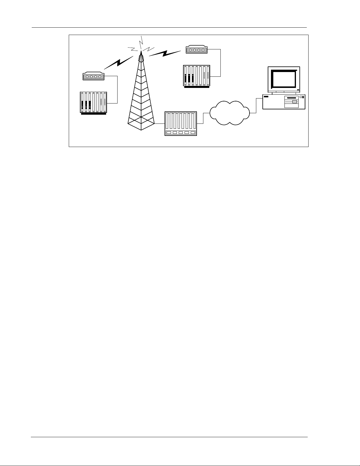
DART 300
DART 300
RTU
RTU
2.1.1. In the Field
The DART 300 is connected to a local device in the field (shown in the figure above as a RTU),
and a power supply (sometimes from photovoltaic cells or batteries). The local host will be
referred to in this document as the Data Terminal Equipment (DTE) even in cases where the serial
connection it uses is configured as communication equipment (DCE). See Section 10.3 for a
discussion of this distinction.
The local device could be something simple like a meter that outputs a data block, at fixed
intervals, containing its readings. This type of device is not capable of receiving or responding to
data; as such it is considered a “dumb” device.
At the other extreme, the local device could be an intelligent device such as a computer running a
multi-tasking operating system like Windows or Linux. T he PC may be responsible for
coordinating the input of several sensors and in turn controlling outputs to various devices. The
local host in this case can manage a complex communication protocol to send telemetry data and
receive operational commands.
Internet
Radio Tower
Base Station
Figure 2-2: Typical DART 300 Telemetry System
Monitoring System
The host device connected to the DART 300 modem does not have to support the Attention (AT)
command set directly to operate with the modem. The modem can be configured to power up to a
state where connection is controlled by the remote host or initiated automatically by the modem.
Devices capable of issuing a configuration string have the added ability to initiate their own
connections; however, these systems should also provide fault recovery capability.
In any case, the DART 300 can provide the data link between the local device and a network
connection to the central monitoring/control station.
2.1.2. The Network Connection
A CDPD Service Provider handles the infrastructure of cellular antenna towers and base stations.
The base station converts radio signals to a standard network co nnection. This may use wires,
fibre optics, or microwave transmissions.
The network connection is usually the Internet (as shown in the figure above) but can be a private
frame relay network if security is an issue.
Page 8 2110212 Rev 1.0
Page 20

User’s Guide System Overview
2.1.3. The Central Monitor
The units in the field are typically linked to a central computer used to monitor, and possibly
control them. In most cases the connection uses a standard Internet service. The monitoring
system can be connected to the network by any means, including another DART 300 using the
CDPD network.
Since this document takes the point of view of the DART 300 in the field location, the central
monitoring system is considered remote while the DART modem is local.
This remote host must be able to receive the data from multiple local field units and distinguish
one from another. This may be done by polling the individual stations in turn, or by maintaining
different IP ports (sockets) for each device.
2.1.4. Client / Server
In any data exchange over IP, there must be a client (originating the session) and a server
(responding to client requests).
If the central monitoring system uses a polling method to collect data, the monitor acts as a client,
soliciting data from the units in the field (servers). Most telemetry installations use polling to
collect data. In this case, the modem is configured as a server to auto-answer the calls from the
central host.
In cases where the field units initiate the call to report an event or periodic block of data, they are
the clients, calling the central server. The central server may maintain many sessions
simultaneously, accepting data and issuing responses. This is more rare, but is still supported by
the DART 300 modem.
2.2. Project Stages
To integrate the DART 300 into a system requires several stages or steps. This outline covers a
typical case but may not apply to all situations.
2.2.1. Stage 1 – Application Planning
The first task is to define the system requirements, and how the various components of the
network should be configured to meet those requirements. Many of these choices have impacts on
other choices such that the whole system needs to be considered and balanced to maintain
integrity.
After reading about the DART 300 in this guide, you should be equipped to make these decisions.
The nature of the local host device may dictate the answers to many of these issues.
Issues to consider are:
• Local host capability. Dumb devices can only transmit. Semi-intelligent devices can receive
commands using a proprietary protocol but cannot issue or manage AT commands to the
modem. Intelligent devices can be programmed to manage the modem using AT commands.
• IP Stack Location. If the host device is dumb, the modem will have to provide the IP stack
and packet service (UDP or TCP). Semi-intelligent devices may or may not include an IP
stack as part of their communication protocol. If the local host is intelligent and implements a
stack, then a SLIP or PPP connection to the DART may be preferred.
• Client/Server. Determine which end will originate connections. The answering station will
require a fixed IP address so that callers know where to route packets. The DART 300 has a
fixed IP address (its Network Entity Identifier or NEI). The central monitoring station may or
may not. If not, then the monitor will have to originate calls to the modem. That makes the
DART 300 modem a server.
2110212 Rev 1.0 Page 9
Page 21

Introduction DART 300 Modem
• Protocol. Selection of UDP or TCP is important to determining the best configuration for
controlling the opening and closing of sessions, maintaining data integrity over large file
transfers, and keeping network overhead low.
• Security. Implementation of the Friends Only feature will depend on the client/server
relationship and whether or not the central host will always use the same IP address. If there
is concern about improper access to the field device, and the DART 300 / local host can act as
a client, then the registration process could be handled manually. This means the local unit is
only connected to the network when it is ready to contact the remote host.
• Power Consumption. If there are concerns about the amount of power available in the field
locations, use of the modem’s sleep modes may be needed. If the local host is capable of
sleeping, the implementation of the Ring Indicator (RI) signal from the modem can be used to
control host wake-ups.
To fully understand the options made available by the DART 300, the system designer should read
the Feature Reference sections (4 through 7) of this manual.
During this first stage, planning may also be needed to resolve the physical installation issues of
power supply, ante nna installation and grounding, and cabling. A review of the Installation
sections (10 and 11) will prepare you for these issues.
2.2.2. Stage 2 – Bench Integration and Testing
Before installation in the field, the DART 300 requires configuration and testing. One or two
units should be set-up on the test bench and connected to the CDPD network and a PC or terminal
device. Following configuration, the modem must be connected to the target host device and
tested.
There are several steps to this testing:
1. Physical connection to: a power supply, a host PC, and an antenna with access to CDPD
coverage.
2. Initial configuration for activation on the CDPD network. This step will test that the modem
can connect to, and register with, the CDPD network, and respond to a PING.
3. Configuration for use with the local host device. This configuration is performed with a
terminal (PC) to prepare the modem for use with the target device.
4. Connection and test with the local host device. This may involve different serial cabling if the
local host is configured as a DCE device. This step tests that the device will work with the
modem and communicate over the network to the monitoring system. Extensive testing of
fault tolerance should be performed to ensure that problems in the field are self-correcting or
can be corrected remotely.
The first two steps above are covered in Section 3, Getting Started. The configuration and testing
with the target device should happen after reading the balance of this guide.
2.2.3. Stage 3 – Field Installation and Testing
Before configuring and installing many units, it is advisable to install one or two field units to
verify power connection and consumption, antenna installation and net work coverage,
connectivity, and end-to-end performance. Only when this stage passes should you rollout the full
system.
Custom power connectors, data cables, and mounting hardware may be required for the field
installation. This step allows you to verify that the connections are working and the system
functions as required.
2.2.4. Stage 4 – Rollout
This involves configuring many DART 300 units. Each must have the same configuration as the
units that passed the field trial; except the CDPD activation (NEI) will be different for each unit.
Depending on the scale of the system, this can b e done by hand or through an automated script.
Page 10 2110212 Rev 1.0
Page 22
3. Getting Started
3.1. Introduction
This chapter guides you through the initial physical set-up of a host terminal (usually a PC) and
the DART 300 modem, for configuration and test purposes. Related start-up issues such as
cellular activation are also covered.
After completing this chapter, you should be able to communicate (DTE to DCE) with the modem
by using AT commands from a host terminal, have the modem connect with, and register on, the
CDPD network (assuming coverage), and have the modem respond to a PING from the network.
This section presumes the modem is in its factory default configuration. The instructions provided
here are only those needed to make the initial connections and do not reflect the full flexibility of
the modem. The Feature Reference sections cover considerably more detail.
Typical application configurations for connection to the target host device are not covered until the
Configuration and Use sections.
3.2. Service Activation
Before you can use your modem for wireless communication you must obtain an I nt ernet
Protocol (IP) address for it from a cellular service provider. This address is often referred to as a
Network Entity Identifier (NEI). This section describes what they will need to know and what
information they will provide to you.
To obtain an IP address for your modem for use on CDPD networks, contact your local CDPD
service provider and give the service provider the Equipment Identifier (EID). This is the
identification number of the radio/modem. A Sierra Wireless modem EID has the following
format:
00-A0-D5-xx-xx-xx
Look for this number on the back of your modem and on a label affixed to the outside of the
package that the modem was shipped in.
The EID number is also available by querying the modem with the AT+WPEID command.
The CDPD service provider supplies the following:
1. Modem IP address, commonly referred to as a NEI. This identifies your modem on the
CDPD network and on the Internet.
2. IP address of a router or server to ping when testing the connection. This may be a Domain
Name Server (DNS).
Both of the above items are in the form of an IP number. This is made up of four numbers
ranging in value from 0 to 255, separated with periods (sample: 192.168.0.9). This is known
as dotted-decimal format.
3. Side designator, A or B. This determines the channels used by your CDPD service provider.
4. SPNI number of the provider. This is optional. The Service Provider Network Identifier
(SPNI) is used when restricting the modem to accepting service from a limited list of
providers, and can help speed up cellular channel acquisition and registration.
This information will be required when configuring your modem for CDPD registration.
Contact your service provider to get this process started. While the service provider is getting
your account configured, you can install and configure your modem. Record the information
provided by your carrie r for configuring the modem later.
2110212 Rev 1.0 Page 11
Page 23

Introduction DART 300 Modem
3.3. Set-up Considerations
The section covers the requirements for a simple test bench installation of the modem. For full
details of the physical installation of the DART 300 consult Section 10.
3.3.1. Power Supply
The DART 300 package does not include a power supply in the box, as most installations have
12V DC power available at the site. For this initial testing a 12.0V DC regulated power source
with a 1 amp capability is required. The unit comes with a power connector cable with bare wire
leads for connection to a DC power supply.
An AC power adapter, using the DART 300 power connector, is available as an accessory from
Sierra Wireless (part 6000082).
If you chose to provide your own cable, a description of the DART 300 power connector is
provided in Section 10.4. Part numbers are provided for those wishing to assemble custom power
supply cables.
3.3.2. Antenna
There is no antenna supplied with the modem as shipped from Sierra Wireless. The antenna you
choose to use should meet your particular installation requirements. Consult Section 10.1 for
details on the antenna requirements. A 3dB gain magnetic-mount cellular antenna, available from
most electronic stores, is suitable for bench testing activity.
An antenna with a hard mount and TNC connector is available as an accessory from Sierra
Wireless (part 6000065).
3.3.3. Serial Cable
A standard RS-232 serial cable with 9-pin male D connector is required (not provided in the
DART package) for connecting the PC host to the DART 300 modem. A suitable cable is
available from Sierra Wireless (part number 6000048) if needed.
3.3.4. Host Computer Terminal
You will require a PC with a communications program capable of operating in ASCII terminal
emulation mode. This allows the PC to function as a terminal attached to the modem and permits
the entering of AT commands required for modem set-up and diagnostics. We recommend that
the program chosen be capable of logging terminal communications activity to a file for later
analysis or printout in the event that technical support is required.
For IBM PC-compatibles, Windows Terminal, HyperTerminal, ProComm, and Kermit are all
acceptable. If you intend to use SLIP or PPP mode, note that early versions of HyperTerminal do
not allow you to send SLIP framing characters to the modem, preventing use of the escape
sequence. This was corrected in later versions.
Communication between the host (DTE) and the Sierra Wireless DART 300 modem is factory
defaulted to:
bps: 19200
Data Bits: 8
Parity: None
Stop Bits: 1
Any application being used to communicate with the modem and issue AT commands must be
configured this way initially. Auto-baud is not supported in the DART 300.
Flow control is implemented in hardware (RTS / CTS) and is not optional.
Page 12 2110212 Rev 1.0
Page 24
User’s Guide Getting Started
As shipped the modem is configured with these settings:
• Echo enabled (E1): which causes the modem to echo characters received from the host back
to it while in command state. The backspace is echoed as <BS> <SP> <BS>.
• Quiet result codes disabled (Q0): which enables the modem to issue result codes following
commands. Quiet on (Q1) suppresses result codes entirely (but not re sponses).
• Verbose result codes (V1): which provides results in English text appended with <CR><LF>.
Verbose off (V0) returns the results as ASCII numeral codes. Numeric codes are preferred
for software processing by intelligent terminal applications.
This configuration means that a PC host running a terminal emulation progr am for initial
configuration of the modem should use these settings:
• Emulation – TTY
• ASCII character
Sending:
• No line ends with line feeds
• No local character echo
Receiving:
• Do not append line feeds to incoming line ends
• Do not force incoming data to 7-bit.
• Wrap lines if necessary
3.4. Connections
This section describes the steps to connect the PC host and DART 300 modem. At the end of this
procedure you should be ready to configure and use the modem. If results at any step are not as
described, consult the chapter on troubleshooting (Section 13).
To connect follow these steps:
1. Attach the RS-232 serial cable (female end) to a COM port of the host PC.
2. Attach the RS-232 serial cable (male end) from the host to the DART DATA connector.
3. Start the terminal application on the host PC. Configure the application for the port connected
to the DART 300. From the factory, the modem requires a setting of 19200 bps, 8 data, no
parity, 1 stop bit, with hardware (RTS/CTS) flow control.
4. Instruct the terminal application to connect.
5. Place the antenna in a suitable location, and attach the antenna cable to the modem.
6. Ensure the modem power switch is OFF.
7. Connect the 12V DC power supply to the DART 300.
8. Switch on the DART 300 power.
The LED indicator should come on dimly. This indicator is used to display the status of the
modem. The modem initializes and in about 6 to 10 seconds the CTS serial signal should
assert and OK should appear on the PC terminal. The LED will become brighter and may
begin to blink.
9. Type AT<enter> at the host terminal. The modem should reply with OK.
The modem is now ready to be used with the host computer. You may continue to configure and
use the modem as described in sections below.
3.5. CDPD Configuration
In order for the modem to register on a CDPD network it must have a unique Network Entity
Identifier (NEI). This is an Internet Protocol (IP) address assigned by your CDPD network service
provider. Section 3.2 Service Activation contains information on activating this service.
The service provider must assign you an NEI and channel side preference. They should also
provide their Service Provider Network Identifier (SPNI) number. To do this, the service provider
will need to know the Equipment Identifier (EID) of the modem, which you can obtain from the
modem by issuing the +WPEID command .
2110212 Rev 1.0 Page 13
Page 25

Introduction DART 300 Modem
The NEI, and side preference are all that are needed to connect with the network. These are
recorded within the modem by using the following AT commands (the AT is omitted for brevity):
1. +WPNEI=ip where ip is the NEI address to assign in dotted-decimal format. You do not
need leading zeroes in the individual elements of the address. When you press <enter> the
modem will respond with a prompt to confirm the change in the table. The old and new
values are both shown.
Press Y (case insensitive) to confirm the change, or
Press N (or any key other than Y) to cancel the command.
The modem will respond with OK if the NEI is in a valid IP form.
2. +WS174=n where n indicates the application of the channel side (A or B) assigned by your
CDPD provider. Values for n are:
1 – A side preferred,
2 – B side preferred,
3 – A side only,
4 – B side only.
Setting one side preferred will mean the modem searches channels on that side first, but will also
check for CDPD channels on the other side should there be no usable signals on the preferred side.
Restricting the modem to one side only will prevent it from scanning the alternate side channels.
This is usually discouraged in mobile settings but can be done in the fixed (non-mobile)
installations for the DART 300.
When these two elements have been entered, the modem will automatically attempt to register on
the CDPD network.
3.6. CDPD Network Registra ti on
Note that network registration must be performed be fore communication ac ross the network can
begin. Registering on the network is distinct from opening a c ommunication session. The
registration process involves an exchange of identification, authentication, encryption keys, and
CDPD sleep characteristics.
Data Carrier Detect (DCD) is tied to sessions, not network registration. A session does not begin
until you originate a (client) session or answer one (as a server).
The modem can be set to register manually (on command) or automatically when it starts or resets.
For this first test auto-registration is used. This is the factory default setting and no additional
action is required for this setup.
3.6.1. Verifying Network Registration
The status of the modem’s registration can be read at register +WS56 (Network Registration
Status). A value of 1 indicates the modem is registered. A value of 0 indicates that it is not
registered.
Page 14 2110212 Rev 1.0
Page 26

User’s Guide Getting Started
The DART 300 LED indicator also reflects the modem’s registration status. The flash patterns are
as follows:
• On steady (not flashing) indicates power is on but no CDPD channel is visible. The modem is
typically scanning for a channel at this time. During the first few seconds from power-up, the
modem is initializing and the LED will appear dim.
• Flashes on once per second if the modem has acquired a CDPD channel but is not yet
registered.
• Flashes on twice per second if the modem is registered on a CDPD channel.
• Off indicates the modem is in CDPD sleep mode (or has no power).
Monitor the modem’s LED indicator to determine if it can acquire a CDPD channel (flashes once
per second). If it fails to do this within a few minutes then check the antenna connection and
placement. Consult Section 10.1 on antenna installation for guidance.
If the modem can acquire a channel but does not register within a few minutes, you can determine
the reason by attempting a manual registration:
1. +WPDEREG to force the modem out of auto-registration.
2. +WPREG to attempt to register manually.
The modem allows up to 30 seconds to register. If it fails, a reason is given. If the modem has
simply timed out, then retry the registration command in step 2.
A message of DENIED_MDIS_INCAPABLE means that the CDPD network is not able to handle
the registration at this time and you should retry later. If the error persists, contact the CDPD
carrier for assistance.
Any other registration failure, with a DENIED_… message, will require the attention of your
CDPD service provider to clear up the problem. Contact them and report the registration failure
message from the modem. Additional troubleshooting assistance is in Section 13.
When the modem has successfully registered, enter:
3. +WS173=1 to restore auto-registration.
3.6.2. PING
After registration, you should confirm that you can communicate with the modem over the
network.
PING is a utility to test connections across an IP network. PINGs are packets of data with special
flags in the header, which advise the protocol stack at the receiving end to echo the packet back.
The sender typically times the duration from transmission to echo receipt to determine the speed
of the network link. The application at the receiving end of a PING has no knowledge of the
transaction. It is handled within Layer 3 of the protocol stack.
When the modem is registered, you can issue PINGs from another CDPD-based modem, or over
the Internet, and the DART 300 should reply. If you are using a SLIP/PPP connection, the stack
on the host will be responsible for replies to PINGs. If you use either the UDP or TCP packet
services in the DART 300 modem, then the modem will handle the PING without the host’s
knowledge.
DART 200
The DART 200 includes the ability to both answer and generate PINGs (*P) but the
DART 300 only supports answering. PINGs from the DART 300 must originate with
the attached host device using a SLIP/PPP mode connection.
2110212 Rev 1.0 Page 15
Page 27

Introduction DART 300 Modem
3.6.2.1. Obtaining a PING from the M odem
This step assumes the modem is registered on the CDPD network.
(AT is omitted for brevity):
1. +WS45=0 or 1 to select UDP or TCP packet service respectively. This will have the modem
reply to the PING without the need of a local host connection.
2. Using a network-connected PC as the remote station, open a MS-DOS Prompt window.
3. At the MS-DOS command line enter:
PING <ip> where <ip> is the registered NEI address of the modem in dotted-decimal format.
(The modem’s NEI can be determined with the AT command +WPCURNEI.) Do not use
leading zeroes in the IP address components. (The PING utility assumes a leading 0 indicates
an octal rather than decimal value).
The modem should reply and the PC will indicate the echo time. Four PINGs are issued by
this command option.
If the PC PING requests timeout without success, try allowing a longer wait time by adding the
parameter –w 5000 to the PING command line. That will allow 5 seconds (5000 ms) for the echo
before the PC will time out the attempt. For a full list of PING command options, enter the PING
command without parameters.
At this point the modem should be functioning on the network and responding to PINGs. The
modem is now ready for configuration and installation as described in the sections on
Configuration and Use.
Should the modem fail to respond, check Section 13, Troubleshooting.
Page 16 2110212 Rev 1.0
Page 28

Feature Reference
4. Local DTE/DCE Interface
This section covers:
• Important terminology on modem modes and states
• Modem buffers
• The AT Command Interface
• The RS-232C control signals
A sound understanding of the interface is important to smooth communication with devices that
may not handle the modem’s AT commands and responses as well as intelligent local hosts that
can exercise full control of the modem.
4.1. Modem Modes and States
The DART 300 modem supports CDPD only but with several packet service modes. Various
states and conditions within each mode are also possible. The commands and registers used
depend on the modem’s operating mode, state of the modem, and its condition. Together these
determine how the modem will behave in any given situation.
Mode indicates the packet service or local connection used by the modem.
State indicates whether data is treated as a modem command or data for transmission.
Condition indicates whether the modem has an active connection to the network.
4.1.1. Modes
The DART 300 supports all of these modes.
• SLIP – The simplest mode of operation, where the local host system provides TCP or UDP
stack services. This is the factory default.
• PPP – A more robust form of SLIP connection where the local host again provides the
protocol stack. This protocol allows the local host and modem to negotiate the features they
have in common to establish the most effective communication.
• UDP – User Datagram Protocol stack is implemented in the modem where serial data is
assembled into packets, or received data packets are disassembled for the local host.
• TCP – Transport Control Protocol stack is implemented in the modem for packet assembly
and disassembly and the management of connection handshaking with the remote.
UDP and TCP modes are also known as PAD modes because the modem’s internal Packet
Assembler / Disassembler (PAD) services are active.
The mode can be changed whenever the modem does not have an open session.
A full discussion of the protocols is covered in Section 6.
2110212 Rev 1.0 Page 17
Page 29

Feature Reference DART 300 Modem
4.1.2. States
The modem’s state, in conjunction with its condition, will govern how the modem handles traffic
to and from the host and to and from a remote modem.
The modem supports two states:
• Command – the modem exchanges data with its host (DTE) as AT commands and replies.
• Data – communication is passed between the local and remote terminals as telemetry data.
4.1.3. Conditions
In addition to mode and state the modem can be in one of two conditions:
• On-line – actively connected with a network session open (off-hoo k).
• Off-line – disconnected, or without an active network session (on-hook).
While in off-line condition the modem can only be in command state.
In the on-line condition, the modem can be:
• In data state which passes data through the mod em between the local host (DTE) and the
remote terminal or network.
• In command state which exchanges data between the local host (DTE) and the modem (DCE)
without passing it thro ugh t he active connec tion to the network.
The modem must be in the off-line condition to change modes.
4.1.4. Sessions
In UDP and TCP PAD modes a session is open when there is an established “call” between the
modem and a client or server on the network (although UDP does not guarantee the other end is
on-line). When a session is open, the DART 300 modem is in on-line condition and the PAD is
active to send and receive data. When the “call” is terminated, the modem is off-line and the
session is closed.
The concept of a session in SLIP and PPP modes is distinct from that in UDP and TCP PAD
modes. From the DART 300 point of view, there is a SLIP or PPP session between the local host
and the modem, which does not extend across the CDPD network to remote clients or servers. To
the local host, there is a SLIP session with the modem and multiple client / server sessions with
remote terminals.
In all modes, when there is an open session, the modem is in on-line condition.
4.1.5. Transition Between States
On power-up the modem is normally in command state. Only if the Auto-dial on Start-up feature
(Section 5.3) is used will the modem transition to data state without the usual transition codes.
4.1.5.1. Command to Data State
The modem changes to data state when a session is opened either by dialling a client session or
answering a server session. When a session opens, the modem issues the CONNECT message
and asserts the DCD control signal.
Page 18 2110212 Rev 1.0
Page 30
User’s Guide Local DTE/DCE Interface
CAUTION
Due to multi-processing in the modem, the DCD signal may be asserted slightly before
the modem has completed the transition to data state. The host device should allow a
delay of 500ms after receiving the CONNECT message and DCD signal before
beginning transmission or there may be some data lost.
Details
UPD and TCP sessions use the D ( Dial) command to open a client session. Se rver sessions are
opened when the modem auto-answers an incoming service request (S0=1) or the local host issues
the A (Answer) command to answer manually (when S0=0). With server sessions, the modem
first sends the RING result. When the modem answers, it issues the CONNECT result. Anything
coming from the modem after that is data from the remote station.
If Quiet is enabled (Q1) then the local host should allow the 500ms delay from the assertion of
DCD before beginning transmissions. For server sessions using Quiet, there are no messages from
the modem’s command processor; therefore all traffic from the modem can be considered data.
SLIP/PPP connections issue either D (Dial) or O (On-line) commands to open a session. The
host’s stack then manages client and server activities. The modem issues CONNECT and asserts
DCD for the transition to data state, just as it would for UDP and TCP sessions.
If the host has escaped from data state and kept the modem in on-line condition, it can return to
data state with the O (On-line) command. The modem will repeat the CONNECT message for
the transition to data state. DCD will have remained asserted to indicate that on-line condition
(the open session) was retained thro ughout.
4.1.5.2. Data to Command State
When the modem changes to command state, there will be an OK result issued. This may be
preceded by another result (such as NO CARRIER) to indicate that the session was closed by an
event outside the modem. A closed session requires the modem to return to command state.
NOTE
A transition to command state from data state does not require that the session be
closed. This means that DCD will remain asserted while the modem is in command
state, on-line condition.
Details
Several events can cause the modem to transition from data to command state based on mode.
UDP and TCP PAD mode transitions:
• The modem receives the Time Dependent Escape Sequence (TDES) (Section 6.6.3.1)
• The modem receives the Time Independent Escape Sequence (TIES) (Section 6.6.3.2)
• DTR is de-asserted, with a configuration to use DTR (&D1 or &D2).
• The UDP or TCP PAD Session Timeout (S30) expires due to inactivity on the connection.
• The remote terminal closes the session (TCP closing handshake).
• The modem is reset or power-cycled (and is not using auto-dial).
SLIP mode transitions:
• DTR is de-asserted, with a configuration to use DTR (&D1 or &D2).
• The modem receives the escape sequence as a SLIP frame (0xC0 +++ 0xC0)
• The modem is reset or power-cycled.
2110212 Rev 1.0 Page 19
Page 31

Feature Reference DART 300 Modem
PPP mode transitions:
• DTR is de-asserted, with a configuration to use DTR (&D1 or &D2).
• PPP negotiates command state.
• The modem is reset or power-cycled.
Details of these methods, and the messages issued by the modem to indicate the transition are
described in the sections on each mode.
4.2. Modem Buffers
Communication with the modem is buffered to allow the modem to provide a variety of features
and speed configurations. This section provides an introduction to the types of buffering
performed by the modem.
4.2.1. Command Buffer
When in command state, the modem will buffer the input from the host until a <CR> is entered.
The buffered data can be edited using the <BS>. There is a limit of 255 characters to one
command line. If the command buffer length is exceeded the modem will return the ERROR
result code without executing any commands in the line.
This buffer is distinct from the data receive and transmit buffers. The command buffer retains the
contents of the last issued command until the AT command prefix is received for the next
command. This allows repeating of the last issued command by entering A/ instead of AT.
4.2.2. Data Buffers
Data being transmitted or received is buffered in several ways depending on the mode and nature
of the connection. Some caution must be taken when disconnecting to ensure that any buffered
data in the modem has been properly processed prior to breaking the connection. Specific settings
for buffer controls are described in the relevant commands and registers. Normal configuration of
the modem will not require you to adjust these settings.
4.2.2.1. Speed Buffering
The simplest form of buffering allows for line speed differences and busy conditions between the
host (DTE) and modem and between the modem and the remote terminal. The CDPD side of the
connection is limited to a speed of 19200 bps while the local host connection can be at one of
many different speeds from 300 to 57600 bps.
Where large amounts of data are being exchanged, local hardware flow control must be used to
prevent buffer overflows. See the discussion of the use of RTS and CTS in Section 4.4.2 for
details.
The CDPD protocol incorporates flow control on the network connection to reduce packet loss.
4.2.2.2. Packet Buffers
When using one of the Packet Assembly / Disassembly (PAD) features of the modem, the data
received from the host is buffered until a forwarding condition (character, packet length, or
timeout) is encountered. The modem then frames the packet with a header and transmits it to the
network.
Similarly, data received from the network is buffered until the packet is complete. The modem
performs integrity checks on the packet and will either reject it or pass the data contents to the host
via speed buffering.
Page 20 2110212 Rev 1.0
Page 32
User’s Guide Local DTE/DCE Interface
4.3. AT Command Handling and Defaults
Even when used with a local host device not capable of issuing commands or understanding
responses, an understanding of the AT command interface is needed for configuration and to
prevent problems in the field.
If the user does not exercise caution in exposing (or hiding) the command interface, the target host
device may inadvertently issue commands that reconfigure the modem, or misinterpret modem
responses as operational commands to the host device. See Section 8.4.1 for a sample case.
4.3.1. General Notes
AT can be issued as a command without parameters. It acts like a “ping” to the modem and will
always give a result code of “OK”. If there is no response from the modem, try issuing ATQ0
(Quiet mode off). If this fails, try the escape sequence or resetting the modem.
More than one command can be included in a single line although some commands or their
parameters must be placed at the end of the line. When concatenating commands, a space between
commands is optional. Commands are executed in the order entered. If a command results in the
ERROR result code the balance of the command line is ignored. Only one result code is returned
for the entire command line.
Commands may be entered in upper or lower case.
See Section 4.2.1 Command Buffer for a discussion of how commands are buffered in the modem.
4.3.2. Parameters
Most AT commands support one or more parameters, usually a number. Parameter ranges are
specified in the AT Command Reference later in this guide.
Commands that normally accept a single numeric option switch ([n]) and are issued without that
parameter, assume a value of zero (0).
CAUTION:
Entering incorrect syntax or a parameter outside of the specified range may have
unexpected results.
For example, entering the command AT&D=2 (instead of the intended AT&D2) will
be parsed as two appended commands: AT&D0 and AT=2. The first command uses
the 0 default as though no parameter is specified. The second command means
“assign the value 2 to the last used S-register”.
Defaults shown in the AT Command Reference are those for the factory settings of the modem
and are not the defaults assumed for a command issued without parameters.
4.3.3. Responses and Results Returned by the Modem
Most commands return only a result code; however some commands request information, which is
provided by the modem as a response prior to the result code.
Human vs. Machine Interface
The AT command interface was designed for human interaction. When an intelligent host is
managing a modem, the interface may need to be altered; result code words replaced with numbers
for example. Framing characters (line feeds and carriage returns) must be properly understood to
ensure the host system properly parses the responses and result c odes.
2110212 Rev 1.0 Page 21
Page 33

Feature Reference DART 300 Modem
As shipped the modem is configured with these settings:
• Echo enabled (E1): which causes the modem to echo characters received from the host back
to it while in command state. The backspace is echoed as <BS> <SP> <BS>.
• Quiet result codes disabled (Q0): which enables the modem to issue result codes following
commands. Quiet on (Q1) suppresses result codes entirely; resp onses remain unaffected.
• Verbose result codes (V1): which provides results in English text appended with <CR><LF>.
Verbose off (V0) returns the results as ASCII numeral codes. Numeric codes are much easier
to process.
With Echo on (E1 – the default) data received from the local host while in command state is
echoed back to the host. This can present problems to machine control, which is not interested in
an echo of its own commands to the modem. In most configurations the echo should be turned
off (E0).
The configuration for the target host is more likely to set Echo off, and Verbose off or possibly
Quiet on.
Framing
The framing of these elements by <CR><LF> will depend heavily on the settings of the modem.
In particular the settings of Echo (E), Verbose (V), and Quiet (Q) modes will alter the framing of
both responses and result codes.
These elements are normally formatted for human reading with a terminal program, however users
wishing to have software read and adjust to these response s and result codes must understand how
they are framed.
4.3.3.1. Framing Characters
The modem will frame replies with carriage return and line feed characters: ASCII values 13
<CR> and 10 <LF> respectively. The modem does not support changes to these values.
If echo is enabled (E1) the modem will append a <LF> to the echoed <CR> from the host. If
echo is off, then there is no <CR> or <LF> prior to the response to the command.
Where the modem issues a response (data) prior to the result code, the response will have a <CR>
and <LF> appended regardless of the echo, quiet, and verbose settings.
The sections below on Responses and Result Codes detail the framing characters to expect. If
there are any problems determining the exact framing of the response and result codes, you should
use a protocol analyzer to monitor the exchanges. For application development, it is a good
practice to have either a software or hardware protocol analyzer available for troubleshooting.
4.3.3.2. Responses
Responses will be in ASCII text with a trailing <CR><LF>. Where a response has more than one
line, each line is terminated with a <CR><LF>. The programmer must know the number of lines
expected in the response.
The responses will have a leading <CR><LF> if Echo is enabled. With echo disabled, there is no
prefix to the ASCII response.
Page 22 2110212 Rev 1.0
Page 34

User’s Guide Local DTE/DCE Interface
Table 4-1: Response Framing
Echo Verbose Quiet
1 1 0
1 0 0
0 1 0
0 0 0
1 1 1
1 0 1
0 1 1
0 0 1
4.3.3.3. Result Codes
The modem normally issues result codes on completion of an AT command. This can be disabled
with Quiet mode (Q1). If Quiet is enabled, there may still be <CR> and <LF> characters
returned from the modem with each command (see the tables below).
The default is to issue results in verbose (English text) form. Numeric codes can be selected by
disabling the verbose option (V0).
Verbose (V1) result codes are returned with a trailing <CR><LF>.
Numeric (V0) result codes are returned with a trailing <CR> without the line feed.
The framing of result codes depends on the command settings of Echo, Verbose, and Quiet, but
also on the presence or absence of a response before the result code.
<CR> <LF> Resp. <CR> <LF>
<CR> <LF> Resp. <CR> <LF>
Resp. <CR> <LF>
Resp. <CR> <LF>
<CR> <LF> Resp. <CR> <LF>
<CR> <LF> Resp. <CR> <LF>
Resp. <CR> <LF>
Resp. <CR> <LF>
For Commands without a Response
If Echo is enabled the modem will echo the <CR> terminating the command line.
The result code appears only if Quiet is off. The result code will be either an ASCII word
(Verbose on) or in ASCII decimal digit(s). If there is a result code (Quiet off) then it will always
be followed by a <CR>.
Table 4-2: Result Framing (No Response):
Echo Verbose Quiet
1 1 0
1 0 0
0 1 0
0 0 0
1 1 1
1 0 1
0 1 1
0 0 1
The modem will insert a <CR><LF> before the result code if and only if Echo is on and Quiet is
off. The trailing <LF> is only included for Verbose results.
<CR> <LF> Result <CR> <LF>
<CR> <LF> Result <CR>
Result <CR> <LF>
Result <CR>
<CR> <LF>
<CR> <LF>
2110212 Rev 1.0 Page 23
Page 35
Feature Reference DART 300 Modem
For Commands with a Response
When a command generates a response, it precedes the result code in all cases. See above for the
framing of the response portion. This discussion is of the framing of the result code after the
response’s trailing <CR><LF>.
The result code itself only appears if Quiet is off. The result code will be either an ASCII word
(Verbose on) or in ASCII decimal digit(s). If there is a result code (Quiet off) then it will always
be followed by a <CR>.
A trailing <LF> will be included if Verbose is on and Quiet is off. Otherwise there is no trailing
<LF>.
Table 4-3: Result Framing (After Response):
Echo Verbose Quiet
1 1 0
1 0 0
0 1 0
0 0 0
1 1 1
1 0 1
0 1 1
0 0 1
4.3.3.4. Possible Result Codes
Result codes are not shown in the AT Command Reference tables unless special conditions apply.
Generally the result code OK is returned when the command has been executed. ERROR may be
returned if parameters are out range, and will be returned if the command is not recognized, or the
command is not permitted in the current mode / state / condition of the modem.
For a full list of result codes, see Table 12-6 in Section 12.5 of the AT Command Reference.
4.3.4. Registers
Some registers are read only. If an attempt is made to write to a read only register, the ERROR
result code is returned.
Result <CR> <LF>
Result <CR>
Result <CR> <LF>
Result <CR>
Some registers store the setting of commands. Cha nging the register is equivalent to changing t he
command setting.
CAUTION:
Entering incorrect syntax or a parameter outside of the specified range may have
unexpected results.
The reference tables for both S and +WS registers indicate the standard default values. The
factory defaults of other settings are also noted in Section 12.6 at the end of the AT Command
Reference.
Page 24 2110212 Rev 1.0
Page 36

User’s Guide Local DTE/DCE Interface
4.4. RS-232C Interface and Control Signals
This sub-section deals with the application of the interface and signals. For information on the
cabling requirements please see Section 10.3.
4.4.1. Interface Settings
Communication between the host (DTE) and the Sierra Wireless DART 300 modem is factory
defaulted to:
bps: 19200
Data Bits: 8
Parity: None
Stop Bits: 1
Any application being used to communicate with the modem and issue AT commands must be
configured this way initially. Auto-baud is not supported in the DART 300.
Flow control is implemented in hardware (RTS / CTS) and is not optional.
The speed settings can be changed to suit the target host device by using the +IPR (I/O Port Rate)
command. The other characteristics of data bits, parity and stop bits are not configurable.
4.4.1.1. Fixed Rate Setting (+IPR)
The modem can be configured to use one specific communication rate. The command allows any
of the following settings: 300, 600, 1200, 2400, 4800, 9600, 19200, 38400, and 57600.
Data bits, parity, and stop bits remain fixed (8, N, 1).
Once the command is issued, the modem does not acknowledge but immediately performs a reset
to apply the new setting. The host should convert rates and monitor for the modem’s OK response
to establish communication at the new rate.
The new setting will be retained and used across all resets and power-cycles until changed by
another +IPR command. The rate is not changed by rest oring factory setti ngs usi ng the &F
command.
4.4.2. Flow Control
The DART 300 requires the use of hardware flow control. If the local host device is not capable
of managing this, the RTS and DTR signals should be tied to the modem’s DSR signal to force
them to an always-on condition.
RTS/CTS is used to control the use of the Rx and Tx signals respectively. Additionally, DTR is
used as a receive flow control in data state.
4.4.2.1. RTS/CTS Flow Control
The implementation of RTS/CTS is to treat each signal as a “permission to send” to the respective
receiver. This is not the historical implementation in which RTS is a request to use the transmitter
and CTS is a reply granting permission.
Host to Modem Flow
CTS is controlled by the modem and indicates to the local host that data can be sent to the modem
on the Tx line. This is used in both command and data states. The host device must ensure that
CTS is asserted before sending commands or data on the Tx line. If CTS is de-asserted, the host
must hold traffic until CTS is again asserted (or risk loss of data).
2110212 Rev 1.0 Page 25
Page 37

Feature Reference DART 300 Modem
Modem to Host Flow
The local host controls the RTS signal. When asserted, it indicates to the modem that it is
permitted to send data to the host on the Rx line. This includes both command state and data state
material. When RTS is de-asserted, the modem will hold all data, command responses, and
replies.
4.4.2.2. DTR Flow Control
There is an additional flow control applied using the DTR signal. When DTR is de-asserted, the
modem will hold data state traffic but will continue to allow both send and receive in command
state (based on RTS/CTS).
Any incoming packets received while DTR is off are held in the modem buffers until a packet
arrives at a time when DTR is on. At that point, all buffered packets are forwarded to the host.
4.4.3. Control Signals
Control signals are useful but not all of them are required in all installations. The modem does
require that RTS and DTR be asserted for data flow to be enabled. This can be forced (as noted
above) if the local host device cannot drive them in a meaningful way. Ring Indicator (RI) and
Data Carrier Detect (DCD) are controlled by the modem and are optional for the local host to
make use of.
4.4.3.1. Data Terminal Ready (DTR)
DTR is used in two ways. The first is part of flow control; the second is to escape data state.
Flow Control
When in data state, the modem treats the DTR signal as a permission to pass received data to the
local host. If DTR is off, the modem will hold received data in internal buffers until DTR is
asserted. DTR has no effect on the transmission of data. This is a one-way flow control, on
received data only, while in data state only.
If the modem is in command state, DTR has no impact on responses and return codes. DTR is
specifically related to data state.
Escaping Data State
Using DTR as a receive flow control in data state is related to using the on-to-off transition of
DTR as a means of escaping from data state to command state.
The modem can be configured to use the on-to-off transition of the DTR signal from the host to
exit data state and enter command state, and optionally close the session. The AT command &D
sets the desired behaviour. The factory default is to hang up any remote connection and enter
command state (&D2).
The available options are:
&D0 Ignore DTR transitions
&D1 Enter command state without changing on/off-line condition
&D2 Hang up (close active session) and enter command state
Page 26 2110212 Rev 1.0
Page 38

User’s Guide Local DTE/DCE Interface
4.4.3.2. Data Set Ready (DSR)
The DART 300 modem will leave the DSR signal active whenever the modem is powered on.
There is no control of this signal. This signal is not an indication that the modem is ready for use.
DART 200
The DART 200 allowed the DSR control signal to be configured to track connection,
RF coverage, or registration status. The DART 300 does not support configuration of
DSR.
When the modem resets or power cycles, the initialization takes approximately 8 seconds.
Provided the host asserts RTS, the modem will send the OK result code. CTS is then asserted
(with or without RTS) to indicate that the modem has completed its internal initialization and is
ready to receive commands or data from the host. If RTS was off when initialization completed,
the OK message will be sent as soon as RTS is asserted.
The DSR signal can be used to force other control signals to the modem (such as DTR and RTS)
to the asserted state. This is done in some null modem configurations and cases where the local
host does not support RTS/CTS flow control.
4.4.3.3. Request to Send (RTS)
The local host must assert the RTS signal whenever it is ready to receive data from the modem on
the Rx line. If the local host is not prepared to accept incoming data for any reason, it must deassert the RTS signal indicating that the modem must hold data until RTS is again asserted. This
is true for both command and data states.
If the local host device does not support hardware flow control, the RTS signal must be tied
active; usually by connecting it to the DSR output of the modem. In this case, data overrun and
data loss are possible .
The modem does not use the original RTS/CTS handshake definition for transmit flow control.
See Section 4.4.2.1 for details.
4.4.3.4. Clear to Send (CTS)
The CTS signal is asserted by the modem when it is ready to receive data from the local host on
the Tx line. If the modem’s transmit buffers fill, the modem will de-assert the CTS signal
indicating that the local host should hold data until CTS is again asserted. If the local host does
not respect this flow control, some data may be lost by the modem. See Section 4.4.2.1 for details.
4.4.3.5. Ring Indicator (RI)
The RI indicator signal can be used as a “wake-up” signal to a sleeping host. Note that the host
must continue to assert RTS while sleeping. When a packet arrives, the modem will assert RI in a
one-second on, three-seconds off, duty cycle (mimicking the ringer on a North American wireline
telephone). The host can then awake, assert DTR, and receive the packet.
Full details of the behaviour and implementation are provided in Section 5.5 below.
2110212 Rev 1.0 Page 27
Page 39

Feature Reference DART 300 Modem
4.4.3.6. Data Carrier Detect (DCD)
Since CDPD modems do not use traditional wireline carrier, DCD is used to indicate the on-line
state of the modem. If there is an open UDP or TCP PAD mode session (either client or server)
then DCD is asserted. When using SLIP or PPP modes the signal is asserted when the modem is
placed in on-line state to the network with the ATO or ATD command.
DART 200
The DART 200 allowed the DCD control signal to be configured to track connection,
RF coverage, or registration state. The DART 300 does not support configuration of
DCD.
Using UDP or TCP mode and enabling auto-answer, the modem can open a server session without
asserting DCD if the host has de-asserted RTS. The modem will not assert DCD until it is able to
send the RING and CONNECT result codes to indicate the transition from command state to data
state. De-assertion of RTS indicates the host cannot receive these messages. As soon as RTS is
asserted, the modem will send the result codes and assert DCD.
CAUTION
Due to multi-processing in the modem, the DCD signal may be asserted slightly before
the modem has completed the transition to data state. The host device should allow a
delay of 500ms after receiving the CONNECT message and DCD signal before
beginning transmission or there may be some data lost.
Page 28 2110212 Rev 1.0
Page 40
5. Product Features
This section covers operational features that add versatility to the modem. Understanding these
features helps you better plan the configuration that will best meet the needs of your installation.
Features covered include:
• Friends Only security
• Dial Directory (“Quick Dial”)
• Auto-dial on start-up
• Sleep modes
• Remote diagnostics and monitoring
• Booster Support
The details of the features of the DART 300 are each covered with:
• A brief description of the feature
• A detailed discussion of it with respect to configuration and impact on other features
• Sample(s) of AT command sequences to implement the feature
5.1. Friends Only
For applications that allow the modem to answer incoming call requests (server mode), a security
feature is available to restrict the modem to only answering “friendly” callers. Friends Only is
available when either the UDP or TCP PAD (Packet Assembly / Disassembly) service is enabled,
but is not used with the SLIP / PPP protocols.
If Friends Only is active, the modem will only respond to packets or connection requests from a
source address in the Friends List. Connection requests from other sources are declined.
CAUTION
The Friends Only feature cannot be used if the calling client is behind a security
firewall or other mechanism that might create “masquerade” IP addresses.
Details
When the Friends Only feature is active, the modem will check the source IP address of incoming
packets. If the address is not on the Friends List: UDP packets are quietly discarded; TCP session
requests are declined (ignored).
This feature requires that the calling system use a known, fixed IP address. If the network
connection used by the monitoring station obtains an IP address through DHCP or some ot her
dynamic IP allocation, then the feature will not be practical. Note that IP masquerading can also
have an impact on the use of this feature.
The modem maintains a list of up to ten friends. If the table is not empty, the feature is enabled
and the comparison of packet source addresses against the list stored in the modem will be made.
If the table is empty (all entries are 000.000.000.000) then the modem will accept calls from any
source.
There is also a space in each entry for a port number. The port number is only used for dialing
features described below.
2110212 Rev 1.0 Page 29
Page 41

Feature Reference DART 300 Modem
Implementation
(AT is omitted for brevity.)
To Read the Table:
1. +WVFRIENDLIST displays the entire table with one line for each entry. The displayed
entries include: index number, IP address, and port.
To make an entry in the table:
1. +WS213=n where n is the index number of the entry to add or change.
2. +WVFRIEND=ip.port where ip is the dotted-decimal IP address and port is a port number
to use for dialing features (described below). The .port number is optional and only needed
if a dialing feature will use this address. If included, it is also dot-delimited.
When you press <enter> the modem will respond with a prompt to confirm the change in the
table. The old and new values are both shown.
Press Y (case insensitive) to confirm the change, or
Press N (or any key other than Y) to cancel the command.
The modem will respond with OK if the NEI is in a valid IP form.
To delete an entry in the table:
1. +WS213=n where n is the index number of the entry to delete.
2. +WVFRIEND=0.0.0.0 to replace the entry with the null value.
When you press <enter> the modem will respond with a prompt to confirm the change in the
table. The old and new values are both shown.
Press Y (case insensitive) to confirm the change, or
Press N (or any key other than Y) to cancel the command.
5.2. Dial Directory
A supplemental application of the Friends Only list is to “quick dial” client sessions to addresses
in the list. The list supports the entry of a port number along with each IP. The port number is
ignored by server sessions when testing incoming pac kets but is used for quick dialing.
Details
The Dial command (D) supports use of a digit parameter (1 – 10) in place of an explicit IP address
and port. The number is the index to an entry in the Friends List. Provided the entry contains a
valid address and port, the modem will use that destination to connect a client session.
The modem must be set to a PAD service mode (UDP or TCP) for this feature to work.
Implementation
(AT is omitted for brevity.)
To enter an address for the dial directory, see Section 5.1, Friends Only, above.
To verify the address for a quick dial:
1. +WS213=n where n is the index number of the Friend List entry to dial.
2. +WVFRIEND? to display the IP address and port entry that will be used.
If the entry is not correct, either change the index value to the correct entry or edit the Friend List
to make the desired entry. See Section 5.1 above for details on displaying and manipulating the
Friend List.
To make a quick dial call:
1. Dn where n is the index number of the Friend List entry to dial.
This abbreviated form of the dial command is useful for applications that configure and connect a
client session using a singl e AT command string.
Page 30 2110212 Rev 1.0
Page 42

User’s Guide Product Features
5.3. Auto-dial on Start-up
The DART 300 has limited support to automatically dial a connection to an IP address and port
configured in the Friends Only list. This feature is only available in TCP or UDP service modes.
For hosts that cannot manage AT commands and responses, it is possible to have the modem autodial a connection to a preset IP and port. This feature is typically used in situations where the
local host will be sending data unsolicited by the monitoring system. Some devices will send a
message based on detection of a particular event.
If the modem does not have an active session, it will be in command state. Unsolicited data from
the local host would feed into the modem’s AT command processor. Should the data parse into a
valid AT command, the modem may be unintentionally re-configur ed.
To ensure the modem has an active session and is in data state at all times, you can configure the
modem to establish a UDP session immediately upon start-up. The disadvantage to this is that the
modem will generate CDPD traffic for each message from the local host whether or not the
monitoring system is connected. The packets would just be dropped in the network if delivery
fails. This added traffic might mean additional cost for the CDPD service.
Details
Upon start-up or reset, the modem can auto-register with the CDPD network and attempt to open a
client session to a preset server address.
CAUTION
This feature has limited application due to the possible failure of CDPD registration or
the failure of the server connection. Use of this feature requires careful configuration
and acceptance that connectivity, and even data state, is not guaranteed.
If TCP is being used, the modem will make one attempt to establish the connection. The modem
must successfully register and handshake the connection within the user-defined timeout set in
register S7 (TCP PAD Timeout). If the modem fails to register, the NO CARRIER result is
returned, if it registers but fails the TCP handshake, the NO ANSWER result is returned. In
either of these cases, the modem remains in command state and does not retry the connection.
For this reason the use of auto-dial on start-up is not recommended in TCP service mode.
If UDP is being used, the modem can report CONNECT without actually having a network
connection. If registration fails, the modem will be in data state but not actually able to forward
packets. Data state can be guaranteed but connectivity is not. This is an accepted characteristic of
UDP.
The feature requires that:
• the valid server IP address and port to be called is entered in the Friends List
• the Friend List Index (+WS213) point to the entry to dial
• the modem be set to auto-register (+WS173=1)
• the UDP Registration Wait Status be set to go on-line immediately (+WS179=0)
The feature is then enabled with +WS216=1. The modem will dial the connection on the next
reset.
CAUTION
Auto-dial using UDP places the modem in data state without verification that the
modem has registered on the CDPD network. In the event the modem fails to register,
the modem will eventually assert flow contro l to the local host.
2110212 Rev 1.0 Page 31
Page 43

Feature Reference DART 300 Modem
Implementation
This implementation description forces use of UDP mode due to the possible fault issues with
TCP.
(AT is omitted for brevity.)
1. +WS45=0 to set UDP service mode.
2. +WS173=1 to ensure auto-registration mode.
3. +WS179=0 to go into data state immediately; without waiting for registration.
4. +WS213=n where n is the index number of the Friend List entry to auto-dial.
5. +WVFRIEND=ip.port where ip is the dotted-decimal IP address and port is a port number
to use for the auto-dial connection.
When you press <enter> the modem will respond with a prompt to confirm the change in the
table. The old and new values are both shown.
Press Y (case insensitive) to confirm the change, or
Press N (or any key other than Y) to cancel the command.
The modem will respond with OK if the NEI is in a valid IP form.
6. +WS216=1 to enable the auto-dial on start-up feature.
7. &W to write the configuration to non-volatile memory.
The modem will invoke the auto-dial on the next reset or power-cycle.
5.4. Sleep Mode
The DART 300 operates on a regulated 12 volts nominal at 1 amp. Power consumption depends
greatly on the local received CDPD signal strength (RSSI), which determines the transmit power
used by the modem, and on the duty cycle of the transmitter. The combination of transmitter
power required by the CDPD network and the quantity and frequency of transmissions will
determine power utilization.
Applications that send data at intervals greater than a few minutes, or only on request, can be
configured to conserve power through the use of sleep modes.
The modem supports CDPD Sleep. This is a network feature that allows the modem to shut down
the radio if there is no traffic for a specified period.
In addition the modem can also use a logic sleep or deep sleep mode to conserve even more
power. This capability works in conjunction with CDPD sleep to avoid any loss of data.
This feature works in all modes of operation.
Details
When the modem is waiting for data from either the host or the network, it does not need to keep
all hardware systems running. The modem can negotia te with the CDPD network to have the
network send a periodic message advising if there is pending traffic. Between these messages, the
modem can be programmed to shut down the receiver (go to sleep). The modem will wake up at
the predetermined intervals to check the network for incoming traffic. If there is no pending
traffic, then the receiver can go back to sleep until the next scheduled notification message.
The DART 300 modem can use this feature and has added additional features called “logic sleep”
and “logic deep sleep” to further reduce power consumption. Each of these sleep modes is
described below.
Applications using TCP should take care in using sleep mode. It is possible that the modem may
enter sleep state during an open session and not be available to receive packets within the TCP idle
timeout. The result would be a lost connection. Even if the connection is not dropped, the remote
terminal may experience extensive retries waiting for the sleeping modem to acknowledge a
packet.
Page 32 2110212 Rev 1.0
Page 44

User’s Guide Product Features
TCP client requests to open a session may have to wait before the modem will acknowledge and
handshake the session. Calling clients must allow sufficient timeouts on establishing a TCP
connection to accommodate a sleeping modem.
CDPD Sleep
This is what is meant by the general term “sleep” mode. CDPD sleep is controlled by setting
register +WS175 (CDPD Sleep Idle Time).
Setting the register to 0 (zero) will disable sleep mode. The modem will keep the receiver active
for immediate handling of any incoming traffic from the network or host. This is a dvised for
systems using TCP connections (via SLIP/PPP or the internal TCP PAD). If the modem were to
go to sleep while a session is open, there can be un-acceptably high levels of unacknowledged
packets and retransmissions from the remote host and possibly lost connections if the session
timer expires while the modem is asleep. Longer duration settings of the sleep idle timer can be
used if sessions have sufficiently long breaks between them.
Sleep is enabled by setting the register to the time, in seconds, from 10 to 3600 (1 hour), during
which the modem must not have network traffic. Provided there is no traffic to or from the
network during that interval, the modem will begin using CDPD sleep.
NOTE
For CDPD sleep to engage, the modem must have negotiated with the network to allow
its use. This means that the setting of the enabling register (+WS175) must have been
done prior to network registration. If the modem has already registered with the
network, changing the setting of the CDPD Sleep Idle Time will have no effect until the
modem is de-registered and re-registered.
The CDPD network advises the modem of the time interval between periodic notification
messages. This is typically 60 to 90 seconds. You should verify with your carrier what interval is
used.
Once sleep mode is engaged, the modem logic will turn off the radio receiver. It will turn on the
receiver at the intervals prescribed by the network to check for traffic. If there is traffic, the
modem will then receive it. Should the network require a CDPD channel hop while the modem is
sleeping, the modem will have to scan for the new channel when it wakes for the next periodic
check. This is handled automatically.
The disadvantage to sleep mode is that traffic from the network will have to wait up to a
maximum of one interval for the next notification cycle before the modem can receive it. This
delay in responding can be too great for some time critical applications. This delay also applies to
PING packets sent to a sleeping modem.
While sleeping, the modem logic is still active and ready to receive data from the local host at any
time. The modem will immediately wake up the radio for local host-generated traffic going out to
the network. There is no delay in sending messages, only in receiving network packets assuming
the modem does not have to scan for channel when it wakes-up (a possible concern to mobile
installations).
NOTE
The LED indicator on the DART 300 will go off while the modem is sleeping. This can
give the mistaken impression that the modem is n ot powered. It will flash briefly with
each wake cycle so some patience may be required to verify the modem is operating.
Logic Sleep
In addition to switching off the radio for CDPD sleep, the modem can be placed in a logic sleep
mode. This further reduces the power consumption of the modem. Logic sleep will not engage
unless CDPD sleep is already engaged.
2110212 Rev 1.0 Page 33
Page 45

Feature Reference DART 300 Modem
If logic sleep is enabled (S31 > 0), it will automatically engage on the next CDPD sleep mode
interval. Logic sleep continues until data, or an AT command, is received from the local host; or
the modem must perform the periodic CDPD sleep mode check. After performing the periodic
network check, and provided there is no pending AT command or traffic from the local host, the
modem resumes both CDPD and logic sleep.
The modem can use logic sleep while in auto-answer mode. The modem logic must wake-up
periodically as part of the CDPD sleep operation to check the network for messages. Incoming
data from the network amounts to a RING when auto-answer is enabled, so the modem logic will
be awake to receive messages.
This feature is controlled with register S31 (Logic Sleep). Setting the register to 0 (zero) will
disable logic sleep. Setting it to 1 will enable normal logic sleep. In this condition the modem
will reduce power until the local host sends a command or CDPD sleep operation requires activity.
It will wake as soon as a character arrives from the local host, or automatically as needed to make
periodic network checks for traffic.
Logic Deep Sleep
Setting the Logic Sleep register to 2 will enable deep-sleep. This will cause the modem to shut
down even more hardware, conserving even more power. Automatic wake-ups to check the
network will still occur so no incoming network traffic is lost, however it will take longer to wake
for incoming local host data.
The disadvantage to logic deep-sleep is that the modem will lose the first incoming character(s)
from the local host (DTE). In fact, the modem will take 80 milliseconds, from the start of the first
incoming character, to wake up. At a communication rate of 19200 bps, the delay is equivalent to
154 characters.
The local host should send a “dummy” character first, which the modem will lose, and then wait
the 80ms delay before sending the complete command or data string.
Implementation
(AT is omitted for brevity.)
1. +WS175=n where n is the idle time in seconds before CDPD sleep is engaged.
2. S31=n where n is the level of logic sleep to apply when CDPD sleep is active:
• 0 = no logic sleep
• 1 = standard logic sleep
• 2 = logic deep sleep
3. &W to write the configuration to non-volatile memory.
Sleep will become active when the modem re-registers.
To force re-registration now:
4. +WPDEREG to de-register from the network.
5. +WS173=1 to engage auto-registration mode and register with CDPD sleep enabled.
5.5. Using Ring Indicator (RI) with Host Sleep
Ring Indicator (RI) can be used as a wake-up signal to the local host if it supports a power-saving
sleep mode. In implementations where the local host acts as a server, providing its data upon
client request, the local host can sleep between sessions. When a packet arrives, the modem will
toggle the RI signal to indicate the local host’s attention is required.
Details
If the local host device is capable of going to “sleep” between sessions and the RI signal is used to
wake it up, attention must be paid to flow control between the local host and the DART 300
modem. Use of the feature will require local flow control be used (RTS/CTS). While sleeping,
the local host should de-assert DTR, indicating the host is not ready to receive data from a client.
Page 34 2110212 Rev 1.0
Page 46

User’s Guide Product Features
RTS must remain asserted, indicating that the RI signal can be passed to the host. If RTS is deasserted, the RING result is buffered until RTS is asserted, and the RI signal is not generated. The
host would not be a dvised of the co nnection request.
The RI signal is toggled on a one-second on : three-seconds off duty cycle; mimicking the ring
pattern of North American wireline telephones. The number of repetitions of this cycle and the
behaviour of the modem will depend on the packet service mode being used.
UDP/TCP
When data arrives from the network, either an accepted UDP packet, or a TCP connection request,
RI is toggled. The modem will also send the RING result once with each connection request.
If the modem is set to auto-answer (S0=1) then the modem will toggle RI once only. The modem
will open the session and expect the local host to wake up. The CONNECT result will be sent
and DCD asserted (respecting RTS flow control). Flow control should be opened promptly; the
modem will continue to hold the session open and buffer incoming data.
The modem will toggle the RI signal up to three times for each connection attempt in cases where
the modem is not set to auto-answer (S0=0). The cycles stop as soon as the host issues the
A (Answer) command. If the host fails to answer:
• UDP will buffer the packet and hold the session pending; subsequent client requests will be
handled according to the setting of the UDP Server Receive Lock (+WS217). When the local
host does answer, the original session is opened and processed.
• TCP will timeout the opening handshake. If the local host attempts to answer after the caller
has given up waiting, the modem will wait for the TCP PAD Timeout (S7) and then issue NO
CARRIER.
The RTS and DTR flow control signals can be used by the host to manage the transition to data
state and buffering in the modem. See Section 4.4.2 above for details on flow control.
SLIP/PPP
For SLIP/PPP, the RI feature is enabled and disabled with the &I (Ring Indicator) command. This
defaults to enabled (set to 1).
Since the modem has no knowledge of the status of individual sessions on the local host’s IP
stack, the modem can only advise the host whenever a message arrives. This means that the
modem will toggle the RI signal whether the host is awake or not, and whether there is an open
client/server session or not.
When the modem has an open data state connection, any incoming messages from the network
will trigger the RI signal to toggle active for 1 second and inactive for three seconds. Note that
this refers to network messages and not necessarily IP packets. The CDPD network may break up
an IP packet into multiple CDPD messages.
The timing of the message arrival and ring indicator toggle will determine how many RI signals
are detected. When a message arrives, the modem will check if the RI signal is already within the
four-second duty cycle. If not then the cycle is started with RI going active. When the foursecond cycle finishes, the modem checks to see if another message is being received. If there is an
active message, then the cycle restarts; otherwise the RI remains off until the next message arrives.
4-Second Duty Cycle
RI
Network Messages
Figure 5-1: RI Timing Diagram.
(Note that /RI is active low)
2110212 Rev 1.0 Page 35
Page 47

Feature Reference DART 300 Modem
Implementation
For UDP and TCP services, there is no configuration required. The RI signal will operate as
indicated above.
For SLIP and PPP connections, the RI signal can be enabled or disabled with the &I (Ring
Indicator) command. To enable RI in SLIP and PPP modes use &I1 (the default). To disable it
use &I0.
5.6. CDPD Radio and Booster Support
The DART 300 is a Class III (600 mWatt) device with full duplex transmit and receive capability.
The modem supports connection to the AirBooster 350 RF Amplifier for applications requiring
Class I (3 Watt) operation.
DART 200
The DART 200 provided a Class I transmitter, capable of 3 Watts, rather than the
DART 300 modem’s Class III 600 mWatt output. Many CDPD coverage areas do not
permit use of the full 3-Watt power and limit mobile transmitters to 600 mWatts. For
users requiring the higher output in areas where it is permitted, the AirBooster 350 RF
Amplifier from Sierra Wireless is available for use with the DART 300 modem.
The AirBooster 350 is an intelligent RF amplifier for boosting some Sierra Wireless
Class III (600mW) CDPD devices to Class I (3W). The amplifier is an “intelligent” booster in
that it does not simply apply a fixed gain to a varying input RF level as a linear amplifier would.
Instead, the AirBooster amplifier takes a constant RF level from the CDPD device and applies as
much gain as the local CDPD system allows at that moment.
A GPS Option is also available for the AirBooster 350, adding a GPS receiver inside the package.
This is available as a field upgrade kit or pre-installed at the factory.
5.7. Upgradability
The DART 300 uses the Sierra Wireless SB300 module. It contains flash memory to allow
software upgrades to be made in the field using the local serial connection. Check the Sierra
Wireless Internet site for information on firmware upgrades.
When new features are added, this document will be updated as well. The web site includes a
document library where updated editions can be found.
Page 36 2110212 Rev 1.0
Page 48

6. Protocols and Packet Assembly Features
This section covers:
• Communication protocols and protocol stacks.
• Protocol Features of UDP, TCP, SLIP, and PPP in DART 300, their advantages and
disadvantages.
• Packet Assembly and Disassembly (PAD) features.
The details of the features of the DART 300 are each covered with:
• A brief description of the feature
• A detailed discussion of it with respect to configuration and impact on other features
• Sample(s) of AT command sequences to implement the feature
6.1. Communication Protocols and Stacks
Data communication protocols are generally discussed in relation to the Open Systems
Interconnection (OSI) model. The OSI model was introduced in 1978 as a long-term project of
the International Organization for Standardization (ISO). It divides the communications process
into seven distinct layers, stacked one above the other, hence the term protocol stack. This is very
different from the computer processing use of the term stack for a LIFO buffer.
Table 6-1: The OSI Model
Layer Description Common Protocols
7 – Application
6 – Presentation
5 – Session
4 – Transport
3 – Network
2 – Link
1 – Physical
This is the window between the end-user application and the
communications process. It includes functions such as login and
password checks, and resource allocation.
Responsible for terminal management such as character set
interpretation (i.e. ASCII, ANSI) and code conversion.
Session management includes data-flow synchronizati on, mapping
addresses with names, handling graceful and abrupt disconnections,
and data buffering. This layer organizes data into Session Protocol
Data Units (SPDUs).
Transport Protocol Data Units (TP DUs) are assembled at this layer.
This can include multiplexing and de-multiplexing, error detection
and recovery, and packet reordering where the network can receive
packets along different routes, which can arrive out of sequence.
Data is organized into packets, which are data frames with network
headers and trailers added including network addressing. The
duties include flow control, handling network service data units,
notifying the transport layer of errors, and possibly sequenced
delivery.
This layer arranges the bits into frames. It also establishes and
releases one or more link connections.
This is the physical connection layer concerned with carrying the
communication of digital data.
Application programs
for file transfer,
e-mail, etc.
Telnet, FTP, SMTP,
etc.
UDP, TCP
IP, SLIP, PPP
Network Interface
Cards, Modems
Transmission Media:
Twisted Pair, Fiber
Optics, Cellular
Radio, etc.
2110212 Rev 1.0 Page 37
Page 49

Feature Reference DART 300 Modem
6.1.1. DART 300 Internal Protocol Stacks
The DART 300 modem is designed to provide the bottom four layers, from the Physical layer (the
radio) up to the Transport layer.
The modem will handle acquiring a cellular channel to provide the physical and link connections.
The DART 300 modem is also capable of supporting the next two layers at the user’s option. The
modem has complete built-in Transmission Control Protocol (TCP) and User Datagram Protocol
(UDP) stacks, and also supports both Serial Line Internet Protocol (SLIP) and Point-to-Point
Protocol (PPP) services.
Network communications can be achieved without the attached end-user device having to provide
an integrated TCP or UDP capability. The modem includes packet assembly and
disassembly (PAD) services to handle the formation of serial data into packets with the required
protocol headers. Simply select the desired built-in protocol by using the appropriate AT
commands and begin your data transfer.
For applications with intelligent hosts using their own software stacks, the modem can be used in
SLIP or PPP mode.
If SLIP or PPP is used, Windows Dial-up Networking can provide the TCP/IP stack (layer 4).
Other Windows-based Internet clients can provide the higher layers for file transfer and other
services.
6.1.2. Packet Service Modes
The DART 300 modem supports four connection protocols:
• UDP PAD +WS45=0
• TCP PAD +WS45=1
• SLIP +WS45=3 (Default)
• PPP +WS45=4
The modem’s packet service mode is set in register +WS45 (Packet Service). This setting can be
made before or after registration on the network. It cannot be changed once the modem starts a
session (is on-line). If a change to packet service is required, the user must close the current
session (go off-line), change the setting, and then establish a new session.
Use of each of the services is described in sub-sections below.
6.2. User Datagram Protocol (UDP)
UDP is the most basic transport protocol provided by the modem. It is a thin protocol, adding
only a port specification to the underlying Internet Protocol (IP). It has the same features as IP;
that is a best effort, connectionless delivery service, with the chief benefit being minimum
overhead.
UDP is not considered reliable because packet delivery is not guaranteed. Packets can be lost,
duplicated, delayed, or delivered out of sequence. These conditions are not detected, and the
sender or receiver is not informed.
UDP is connectionless because sender and receiver are never logically connected. If the intended
receiver is not active and available the message is lost. It is a best effort delivery, because the IP
software makes an earnest attempt to deliver the packets, failing only if system resources are
overloaded or the underlying networks fail.
Application programs using UDP must accept full responsibility for handling the problems of
reliability, including message loss, duplication, delay, out-of-order delivery, and loss of
connectivity.
Programmers often treat these problems casually. Testing done when using highly reliable, low
delay local networks may not expose potential failures. This explains why many applications that
Page 38 2110212 Rev 1.0
Page 50

User’s Guide Protocols and Packet Assembly Features
use UDP work well in a local environment but often fail in dramatic ways on a more global
network.
The DART 300 is capable of acting as a client – originating sessions by “dialing” a remote IP and
port, or as a server – opening a session when a packet arrives from a remote client. Most
telemetry applications use a server configuration, allowing the device to answer a poll.
Once a session is open, the modem’s Packet Assembly and Disassembly services are used to send
and receive data. These services are described in Section 6.6 below.
When the session is no longer needed it should be closed as described below in Section 6.2.3. It is
permissible to leave a UDP session open at all times in CDPD, as you are only using the service
when packets are actively being exchanged. If this is done, client sessions will only exchange data
with the dialed client address and port; server sessions can be set up to serve one or more clients in
a single session as detailed below.
6.2.1. UDP Server Features
When acting as a server, the modem can restrict connections to specified “friendly” IP addresses
(Section 5.1 above). Server sessions can be answered automatically or under AT command
control from the local host. The DART 300 also supports a UDP Server Receive Lock. This
allows the modem to serve requests from multiple clients in a single session, by queuing incoming
packets from differing clients until previous requests have been responded to or a timeout expires.
The modem will listen to a specific port (set in +WS212) for client requests. All callers must
send packets to the modem’s IP address (NEI) and this port number. Packets addressed to a
different port will be discarded.
6.2.1.1. Answering UDP Server Sessions
Server sessions are opened when the modem answers a calling client. The modem can be set to
auto-answer (S0=1), the default, or have the host control answering (S0=0). When a packet
arrives to open a UDP session, the modem notifies the host with the Ring Indicator (RI) signal and
RING message, under the flow control described in Section 4.4.2 above. When answered, the
modem sends the CONNECT message and asserts the DCD signal.
When a session is opened, the modem handles packet assembly and disassembly for outgoing and
incoming data respectively. For details on packet assembly and forwarding see Section 6.6 below.
The session belongs to the calling client IP address and port under the rules of the UDP Server
Receive Lock. Host replies will be forwarded to the client that originated the last message
delivered to the host.
6.2.1.2. UDP Server Receive Lock
A server can receive calls from multiple client devices. Note that each call from a specific
computer can appear as different clients because different source ports are used for each session.
The server modem can only save one client address and port for sending any replies; the one that
was extracted from the last datagram received. For this reason, if multiple clients are expected,
the serving DART modem must use receive locking to delay accepting subsequent datagrams until
a response is sent to the source of the prior datagram.
The modem can be set to have sessions belong exclusively to one individual client where packets
from other clients are quietly discarded until the current session is closed; or the modem can use a
single server session to respond to multiple clients. This feature is controlled with register
+WS217.
Details
When register +WS217=0 (the default), the receive lock is disabled. In this case, the modem will
only accept packets from the first calling client until the local session is closed. Packets from
2110212 Rev 1.0 Page 39
Page 51

Feature Reference DART 300 Modem
other callers are dropped. If the calling client closes its session and then dials a new session, it
will likely use a different port number and thus appear as a new (different) client call.
If the value is non-zero, the modem will accept packets from other clients but buffer them based
on the locking time (from 0.1s to 25.5s) set in the register.
The modem will queue client packets, expecting the local host to respond to each client in turn.
As each response is sent, or the timer expires, the next client in the queue is allocated the session.
The client’s packets are delivered to the local host, up to (but not including) a packet from a
different client. A new lock is set and the timer restarts.
Packets are delivered in the order they are received. If more than one packet arrives from a given
client, those packets that arrive without intervening ones from another source will be delivered to
the host as a set. Only one response is needed to clear the lock and allow the next client’s
packet(s) t hrough.
If packets arrive from the currently active client while the local host has not replied, and the
modem has not received packets from other clients, then the packets will be delivered to the local
host immediately. These are packets from the currently active client. Buffering of packets begins
with the first packet from a client other than the active one. From that point, all packets from any
client (including the active one) are placed in the queue on a first-in first-out (FIFO) basis,
pending release of the lock.
Implementation
To use a UDP Server configuration without a server lock (AT is omitted for brevity):
1. +WS45=0 to set UDP mode
2. Optionally set the Friends List as described in Section 5.1.
3. +WS217=0 to disable the Server Receive Lock.
4. +WS212=n where n is the port number (from 1025 to 4999) the modem will listen to for
client session requests. The default is port 2100.
5. S0=1 to set auto-answer (or S0=0 for manual answer).
6. &W to save the configuration.
Provided the modem is registered on the CDPD network, it is now ready to receive client requests
for unique client/server sessions.
To use a UDP Server configuration with a server lock:
1. +WS45=0 to set UDP mode
2. Optionally set the Friends List as described in Section 5.1.
3. +WS217=n where n is the duration (in tenths of a second) to allow the host to respond to a
client before giving the session to the next caller.
4. +WS212=n where n is the port number (from 1025 to 4999) the modem will listen to for
client session requests. The default is port 2100.
5. S0=1 to set auto-answer (or S0=0 for manual answer).
6. &W to save the configuration.
Provided the modem is registered on the CDPD network, it is now ready to open a server session
for multiple clients on a first-come first-served basis.
6.2.1.3. Disabling the UDP Server
It is possible to completely disable the UDP server so that no client requests will ever be accepted.
This prevents the RI signal and RING message from occurring. The modem will only be able to
act as a client. The modem will actually respond to client requests with an indication that there is
no server available.
To disable the server side entirely, set the listening port to zero: +WS212=0.
Page 40 2110212 Rev 1.0
Page 52

User’s Guide Protocols and Packet Assembly Features
Disabling the server does not prevent the modem from answering a PING or from responding to
the Sierra Wireless GroupWatcher
™
remote monitoring program.
6.2.2. UDP Client Features
When the modem dials a client session, it will randomly generate a source port number for the
session. The called server will pick up this port number from the packet header in order to route
replies to the correct client process. Each session is assigned a new originating port number so
that delayed replies to closed sessions will be discarded.
Client sessions can be dialed by a local host AT command, or automatically when the modem
starts. Auto-dial on Start-up is discussed in Section 5.3 above. The following description is for
local hosts using the dial command.
The Dial command (D) can dial any IP and destination port, or it can “quick dial” a member of the
Friends List (Section 5.1). When dialing, the modem can immediately change to data state or wait
to ensure regist ration before connecting.
Details
If the modem is not registered when the dial command is issued, the modem will automatically
begin the registration process. Since UDP is “connectionless”, the modem allows the transition to
data state immediately after the dial command without waiting for registration to complete.
Register +WS179 controls this feature.
When +WS179=0, the modem will return the CONNECT result, assert DCD, and transition to
data state without waiting for registration. If registration fails, the local host will have no way of
knowing unless it escapes data state and queries +WS56. The modem will continue to try to
register indefinitely. The local host can send packets to the modem buffers and close the session.
The modem will continue to try to register and send the packets even after the local host closes the
session.
If +WS179=1, the modem will wait up to the duration set in register +WS198 (Registration Wait
Time) for the modem to register. If the modem is successfully registered within the time allowed,
the CONNECT result is returned, DCD is asserted, and the modem transitions to data state. If
registration fails, the NO CARRIER result is returned and the modem remains in command state,
waiting for another command. The local host must be able to manage these connection failures.
Implementation
For a discussion of Auto-dial on Start-up, consult Section 5.3.
For a discussion of the Dial command, consult the AT Command Reference, Section 12.2.
6.2.3. Closing UDP Sessions
Sessions remain open until one of these events occur:
• The modem receives the command to hang-up (H) the session. This assumes the host has
escaped data state as described in Section 6.6.3 below.
• DTR is de-asserted, presuming the modem is configured to use DTR for this (&D2).
• The PAD Session Timeout (S30) expires due to inactivity on the connection.
• The modem is reset or power-cycled (and is not using auto-dial).
For applications where distinct sessions are desirable (exclusive connections to differing remotes)
and the host device is unable to issue the escape sequence and hang-up command, or toggle DTR
to close the session, UDP can still use the PAD Session Timeout (S30) to close sessions. This can
place significant restrictions on the timing of sessions.
2110212 Rev 1.0 Page 41
Page 53

Feature Reference DART 300 Modem
6.2.4. UDP Broadcast and Multicast
These services are implemented in the DART 300 modem but require implementation by the
CDPD carrier as well. Few carriers have provided this support.
Broadcast and multicast are CDPD functions that support sending the same data to a large group
of IP Addresses with a single transmission to the CDPD network. This capability is implemented
through Mobile Data Intermediate System (MDIS) software. Check with your carrier to determine
if these capabilities are offered before planning to use it as part of your application.
Broadcast and multicast transmissions are point-to-multi-point and provide a one-way,
unacknowledged connectionless service similar to UDP. The operational considerations are:
• Protocol restrictions prevent broadcast or multicast messages from being encrypted.
• Broadcast or multicast data packets will not be received by a DART 300 modem with an
active TCP PAD session.
• If a UDP PAD session is active the broadcast and multicast messages will be interspersed
with the application data packets and must be separated by the application.
• In the case of SLIP, the disposition of the broadcast and multicast messages is a function of
the support provided by the software stack and end-user applications (one must be UDP)
operating on the Mobile Application Subsystem (MAS). If a UDP session is not active, the
messages will be lost.
6.2.4.1. Broadcast
The Broadcast function is used on a geographic coverage basis. To support this function the
MDIS is set up with a Broadcast NEI that includes a list of the Mobile Data Base Stations
(MDBSs) in the desired broadcast area in its definition. There can be multiple broadcast areas
within the coverage area of a single MDIS. A message is transmitted to a Broadcast NEI at the
MDIS that replicates the message, puts a special broadcast header on it, and sends it to the MDBSs
indicated by the broadcast list.
For most applications broadcast is not appropriate, because broadcast messages are sent to all the
CDPD modems in the covered geography. It is more useful to be able to specify that messages
only go to all, or a subset of the IP Addresses associated with a specific customer; a capability
offered by multicast.
6.2.4.2. Multicast
Multicast is set up similarly to broadcast, except that the MDIS is set up with a Multicast NEI and
a list of the terminals that belong to that specific group rather than a list of cells, as used by the
broadcast function. The message to be multicast is sent to the Multicast NEI at the MDIS, which
replicates the message and sends individual messages to the terminals indicated in its multicast
group list.
A terminal can be a member of any number of multicast groups, however it can only be active in
one at any given time. A terminal wishing to receive multicast messages indicates its readiness by
registering a Multicast NEI and by being ready to receive UDP datagrams. The latter can be
accomplished by having the UDP Server function set to active, or if in SLIP mode, by having a
UDP application set to ready. In all of the preceding cases the local host application is assumed to
be ready to process any incoming multicast datagrams.
Contact the service provider for information on the availability and use of multicast service in
your area.
6.2.4.3. Configuration and Use
The mechanism to configure and use the DART 300 for UDP broadcast and multicast will be
described in an application note at a later date. Check the Sierra Wireless website from time to
time for additional information.
Page 42 2110212 Rev 1.0
Page 54

User’s Guide Protocols and Packet Assembly Features
6.3. Transmission Control Protocol (TCP)
Transmission Control Protocol (TCP) is an advanced transmission protocol that adds substantial
functionality to the underlying Internet Protocol it is built on. Because of this structure it is often
referred to as TCP/IP. The advantage of TCP is reliability of data transmission; achieved by using
positive acknowledgements with automatic retransmission if required. The main disadvantage is
the overhead needed to provide this reliability under various conditions.
Unlike UDP, TCP offers both reliable and connected data transmission service. Lost, delayed,
duplicated, or out of sequence packets are detected and automatically corrected. A logical point-
to-point connection is established a nd maintained throughout the communications sessio n. It
requires very little other than session establishment, sending data over the serial port, and session
termination to get a basic application operational.
The price for this reliability is the number of extra data packets used and the time required to
process them. Both need to be considered when selecting an application protocol.
The DART 300 is capable of acting as a client – originating sessions by “dialing” a remote IP and
port, or as a server – opening a session when a connection request arrives from a remote client.
Once a session is opened, the modem handles packet assembly and disassembly for outgoing and
incoming data respectively. For details on packet assembly and forwarding see Section 6.6 below.
6.3.1. TCP Handshaking
Connection establishment requires a three-way handshake between the caller (client) and the
receiver (server). Once established, there is an optional inactivity timer available in the modem to
monitor the connection. If the connection is idle for the time specified, the session is closed.
There is also a closing handshake between TCP partners. This is the significant advantage in
using TCP with “dumb” local hosts. The modem can act as a server, opening the session when
requested by the polling client. The client can then close the session when done and the
DART 300 modem will also close the server side of the session, without the need of commands
from the local host. UDP is not capable of doing this.
6.3.2. TCP Server Features
When acting as a server, the modem can restrict connections to specified “friendly” IP addresses
(Section 5.1 above). Server sessions can be answered automatically or under AT command
control from the local host.
The modem will listen to a specific port (set in +WS212) for client requests. All callers must
send packets to the modem’s IP address (NEI) and this port number. Packets addressed to a
different port will be discarded.
6.3.2.1. Answering TCP Server Sessions
Server sessions are opened when the modem answers a calling client. The modem can be set to
auto-answer (S0=1), the default, or have the host control answering (S0=0). When a TCP
connection request arrives, the modem notifies the host with the Ring Indicator (RI) signal and
RING message, under the flow control described in Section 4.4.2 above. When answered, the
modem sends the CONNECT message and asserts the DCD signal.
When a session is opened, the modem handles packet assembly and disassembly for outgoing and
incoming data respectively. For details on packet assembly and forwarding see Section 6.6 below.
The session belongs to the calling client IP address and port exclusively. While the session is
open, connection requests from other clients will be quietly declined.
2110212 Rev 1.0 Page 43
Page 55

Feature Reference DART 300 Modem
6.3.2.2. Disabling the TCP Server
It is possible to completely disable the TCP server so that no client connection requests will ever
be accepted. This prevents the RI signal and RING message from occurring. The modem will
only be able to act as a client. The modem will actually respond to client requests with an
indication that there is no server available.
To disable the server side entirely, set the listening port to zero: +WS212=0.
Disabling the server does not prevent the modem from answering a PING or from responding to
the Sierra Wireless GroupWatcher
6.3.3. TCP Client Features
When the modem dials a client session, it will randomly generate a source port number for the
session. The called server will pick up the port number from the packet header in order to route
replies to the correct client process. Each session is assigned a new originating port number.
Client sessions can be dialed by a local host AT command, or automatically when the modem
starts. Auto-dial on Start-up is discussed in Section 5.3 above. The following description is for
hosts using the dial command.
The Dial command (D) can dial any IP and destination port, or it can “quick dial” a member of the
Friends List (Section 5.1 above).
Details
If the modem is not registered when the dial command is issued, the modem will automatically
begin the registration process. The time allowed for registration is set in register +WS198 and
ranges from 1 to 255 seconds (default is 30s).
When registered, the modem will initiate the TCP handshake process. The modem allows a
limited time for the server to respond (S7). This time can range from 15 to 255 seconds (the
default is 30s). The modem will retry the connection request at ten second intervals for up to three
tries. If the server fails to reply within the time allowed, the modem will return the NO
ANSWER result cod e .
™
remote monitoring program.
Both the registration timer (+WS198) and the TCP handshake timer (S7) start when the dial
command is issued. If the modem fails to register within the TCP handshake timeout, the modem
will return the NO CARRIER result code.
The modem must register before the TCP handshake can begin. The modem is normally set to
auto-register so that it is available to issue the TCP handshake without undue delay.
6.3.4. Closing a TCP Session
Sessions remain open until one of these events occur:
• The modem receives the command to hang-up (H) the session. This assumes the host has
escaped data state as described in Section 6.6.3 below.
• The remote terminal closes the session (TCP closing handshake).
• DTR is de-asserted, presuming the modem is configured to use DTR for this (&D2).
• The PAD Session Timeout (S30) expires due to inactivity on the connection.
• The modem is reset or power-cycled
For applications where distinct sessions are desirable (connections to differing remotes) and the
host device is unable to issue the escape sequence or toggle DTR, either the remote station can
close the session or the PAD Session Timeout (S30) can close session automatically.
If the local host initiates the close (H, DTR, or reset) then the modem returns the OK result. If the
session is closed by the remote terminal or session timeout, then the modem responds with the
NO CARRIER result.
Page 44 2110212 Rev 1.0
Page 56

User’s Guide Protocols and Packet Assembly Features
6.3.5. TCP and Sleep Mode
Due to the positive acknowledgements used in TCP, use of sleep modes in the modem must be
carefully considered. If the modem goes to sleep during an open session, the possible delays in
sending and picking up acknowledgements can re sult in excessive re-tr ansmissions and even lost
connections. Most telemetry applications will not experience a problem, however attention to
timing is required.
6.4. Serial Line Interface Protocol (SLIP)
SLIP is one method for encapsulating packet data over dedicated and/or switched serial lines. It is
a useful and reliable way to allow mixes of hosts and routers to communicate with one another in
various combinations.
This protocol is useful if the local host application must have multiple sessions active
concurrently. The modem’s own PAD modes can only support one session at a time. If the host
system can manage multiple sessions (sockets) then SLIP is a good choice.
When operating in SLIP mode, the modem’s internal Packet Assembly / Disassembly (PAD)
services are bypassed and the modem acts as a router passing data between the host’s protocol
stack, and the CDPD network. All protocol headers are the responsibility of the host as is the
SLIP framing of the packets. The modem will parse the SLIP frame character to distinguish
packets and to identify the data state escape sequence.
All session management including handshaking TCP session requests, or iginating client sessions,
and processing PINGs are the responsibility of the local host system.
Note that the SLIP protocol does not support auto-answer. If the modem was in auto-answer in
another packet service, it will be ignored when SLIP is selected. Attempts to set the auto-answer
register (S0) will return the ERROR result code. Auto-answer is meaningless in SLIP mode as
the data coming in from the network is passed to the local host and the host can choose to accept
(answer) the call or decline the connection (or discard the packet).
The modem does not have a direct entry to data state in SLIP mode from a reset or power-up. The
modem requires the host to send the ATO command to go on-line (open the session) when the
host is ready to send and receive traffic.
Data state remains active until one of the following events:
• The modem receives the escape sequence as a SLIP frame (0xC0 +++ 0xC0)
• DTR is de-asse rted, presuming the modem is configured to use DTR (&D1 or &D2).
• The modem is reset or power-cycled
6.5. Point-to-Point Protocol (PPP)
PPP offers a more robust connection than SLIP. The modem and its host negotiate a variety of
elements of the connection using PPP messages. The modem advises the local host of what
features are available and the host enables or disables the available features as needed.
When operating in PPP mode, the modem’s internal Packet Assembly / Disassembly (PAD)
services are bypassed and the modem acts as a router passing data between the host’s protocol
stack, and the CDPD network. All protocol headers are the responsibility of the host as is the PPP
management of the packets.
The implementation in the DART 300 modem is minimal. Although the modem is capable of
replying to PPP negotiations, few features are available. The implementation has been tested and
will successfully establish a connection under Windows (95, 98, NT, 2000) and Linux.
The modem can advise the host of the current IP (NEI). Encrypted passwords and data
compression are not available in the modem.
2110212 Rev 1.0 Page 45
Page 57

Feature Reference DART 300 Modem
PPP defines the needed messages to send commands, initiate and close connections, and terminate
sessions. A detailed discussion is not provided here. The reader is advised to consult a PPP
definition document.
6.6. Packet Assembly Management
Once in data state with either the UDP or TCP Packet Assembly / Disassembly (PAD) enabled
(+WS45=0 or 1), the modem accepts data from the host (DTE) and assembles it into packets.
Packet assembly is largely transparent to the local host but some assembly management features
are available.
Additionally, care must be taken in controlling the packet forwarding conditions the modem uses
to close and forward a packet to the network.
6.6.1. Assembling a Packet
A packet is started when the host starts sending data to the modem. The modem will buffer the
data as it assembles the packet. This continues until one of the packet forwarding conditions is
met as described in Section 6.6.2 below.
6.6.1.1. Local Echo
The modem can echo characters from the host back to it, for cases where a terminal application is
being used to allow individuals to type and send messages in real time. This is similar to Internet
Relay Chat (IRC). Setting +WS62=1 will enable the echo (the default) and setting +WS62=0
will disable it.
Local echo is normally disabled when the modem is connected to a telemetry device. In many
cases the local device is not capable of receiving data and those systems that can receive data are
looking for messages from the remote terminal rather than echoes of their own data.
6.6.1.2. Real Time Data Entry and Editing
The modem can optionally allow editing of the packet buffer. Setting +WS72=1 (the default)
will enable local editing of the data before it is forwarded to the network. This allows you to
backspace using the character set in +WS73 (the default is 8 <BS>). If local echo is also enabled
then the modem will echo the backspace character, a space, and another backspace.
This feature is rarely used with automated devices; it is provided to accommodate human errors in
typing. If the telemetry data is binary, then this feature should be disabled (+WS72=0).
Otherwise the modem may receive the backspace character in the data stream and process it rather
than including it in the data. The result would be data corruption.
6.6.2. Forwarding a Packet
The modem closes and sends a packet when one of the following events occur:
1. The modem receives the PAD Primary Forwarding Character set in register +WS64. This
character defaults to 13, the carriage return <CR>. The feature is enabled by default and can
be controlled with a bit mask option set in register +WS63. The options are:
0 Disabled (the packet is only forwarded on maximum length or inter-character timer)
1 The packet is terminated and sent; the forwarding character is discarded.
3 The forwarding character is included in the packet before the packet is closed and sent.
The default setting is 3.
2. The PAD Inter-Character Timer (+WS70) expires. This timer is disabled (set to 0) by
default. It can be set to values from 0.1 to 25.5 seconds. If particularly short times are used
for applications with human data entry, real time typing will be forwarded virtually as it is
received. This means that there is tremendous overhead with protocol headers applied to
packets containing only one byte of data.
Page 46 2110212 Rev 1.0
Page 58

User’s Guide Protocols and Packet Assembly Features
In most telemetry applications, the data is fed from the host in a stream with little or no delay
between characters. When there is a delay at the end of a stream, this setting can have the
modem close and forward the packet.
3. The maximum packet buffer length set in +WS74 (default 1000) is reached. You may wish
to set this value smaller if you are encountering too many packet errors and retransmissions.
Although larger packets reduce overhead, if lar ge packets are being retransmitted, throughput
may improve by using shorter packets. Setting it below 5 will preclude use of the TIES to
exit data mode. The time dependent escape sequence is still available. See below for details.
The actual size of TCP packets transmitted may be less than the size of the PAD buffer. TCP
includes an exchange during the session opening handshake in which the largest expected
packet size is declared. If this size is less than the buffer length, the DART 300 will
automatically fragment the buffer into multiple packets to meet connection restrictions.
4. The time dependent escape sequence (guard time, +++, guard time) is received. The escape
characters are discarded and the packet is closed and sent. The modem then goes to command
state on-line condition, keeping the session open.
CAUTION
If you disable the primary forwarding character (+WS63=0) and the timer
(+WS70=0), the only practical way to forward packets will be to fill the packet buffer.
This is very strongly discouraged.
NOTE
Using DTR (with the &D2 setting) or the Time Independent Escape Sequence (TIES)
will discard any partially assembled packet. A partial packet will also be d iscarded if
the PAD Session Timeout (S30) expires with data still in the packet buffer.
If DTR is used with &D1, the partial packet remains in the buffer (not forwarded). If
the session is then closed, the packet buffer is discarded. If the local host goes back online without closing the session, the partial packet is still in the buffer; subsequent data
will be appended.
6.6.3. Escaping Data State
When using a PAD service mode, the transition from data state to command state can be achieved
in the following ways:
• TDES – Time Dependent Escape Sequence. This is the traditional “+++” style escape using a
guard time before and after the escape characters to prevent accidental escape during a binary
transfer.
• TIES – Time Independent Escape Sequence. This does not require special timing by the host.
• DTR – Data Terminal Ready control line. An on-to-off transition of DTR can be used to
transition to command state and optionally close the session.
• PAD Session Timeout – There is a possibility that the modem will lose signal and/or
registration causing PAD sessions to timeout on inactivity.
• TCP closing handshake – Connections can be closed by the remote terminal. If this happens,
the NO CARRIER message is presented. The modem will close the session and revert to
command state.
Each is described in detail below.
6.6.3.1. Time Dependent Escape Sequence (TDES)
Where the local host device is capable of controlling the timing of data being fed to the modem,
the more traditional time dependent escape sequence can be used. This sequence requires that
transmit data to the modem be idle for a minimum guard time (set in register S12) followed by an
2110212 Rev 1.0 Page 47
Page 59

Feature Reference DART 300 Modem
escape character (defined in register S2), usually the plus sign “+”, repeated three times; followed
by another idle guard time period. The escape characters must not be spaced by more than the
guard time or the sequence is broken.
Guard Time
Transmit Data
1
+++
T
2
Guard TimeT
Figure 6-1: Time Dependent Escape Sequence Timing Diagram.
In the figure above, Transmit is idle for more than the guard time before the first escape sequence
character. The time between characters (T
and T2) must be less than the guard time. If either is
1
equal or greater, then the sequence is broken. The escape character must be repeated three times
without other intervening characters. Finally, the transmit data line must be idle after the third
character for at least the guard time.
If the sequence is detected, the modem will:
1. Discard the escape characters.
2. Close and forward the packet to the network.
3. Transition to command state (remaining in on-line condition with the session open).
4. Issue the OK result code.
There are several inter-relationships to take special note of. These are described below after
detailing the setting of guard time and escape character.
Guard Time
The guard time is controlled by setting register S12 (Guard Time). The value is in units of 1/50
of a second (0.02s). The range is 0 to 255 meaning a maximum guard time setting of 5.1 seconds
and a minimum applied time of 0.02 seconds.
th
It is possible to disable the use of the guard time by setting the value to zero (0) (the default
setting). If disabled, the escape character sequence can use any timing whatsoever; only the series
of three successive escape characters is needed.
Escape Character
The character used for this escape sequence is user defined. The value is stored in register
S2 (Escape Character) and defaults to the plus sign “+” (ASCII value 43, 0x2B). Note that values
greater than 127 will disable TDES.
Important Relationships
The time dependent escape sequence is detected ahead of the time independent version (TIES,
described below). This means that either TDES or TIES should be enabled, but not both.
If both were to be enabled, and the escape character (S2) is the plus sign, use of TIES will require
that the time between the uppercase “T” and the first plus sign “+” be less than the guard time. If
not then the TDES will take precedence and the leading “AT” in the TIES will remain in the
packet buffer and will be forwarded to the network. This problem will occur if both sequences are
enabled and the guard time (S12) is zero.
To ensure TIES can be recognized, disable TDES by setting the character in S2 to a value greater
than 127. Alternatively, to disable TIES and use only TDES then set +WS60=0.
Controlling the guard time is critical to proper detection of the sequence and handling of the
packet. There are interdependencies between the guard time (S12) and the packet inter-character
timer (+WS70).
If +WS70 < S12, i.e. the inter-character timer is less than the guard time, then the modem will
detect a closed packet before detecting the escape sequence. In order to start the escape sequence,
Page 48 2110212 Rev 1.0
Page 60

User’s Guide Protocols and Packet Assembly Features
the line must be idle for at least the guard time. By the time that elapses, the inter-character timer
will have expired and forwarded the packet. If the escape character sequence is then started, the
modem will hold the new buffer until the TDES has either been broken (the characters become
part of the packet) or completed (the modem escapes to command state).
If +WS70 > S12 then the TDES can be used normally. Any partial packet up to the beginning of
the escape sequence will be forwarded when the TDES is detected.
Cases where the buffer is within one or two characters of reaching its maximum length (+WS74)
are protected. Whenever a partial packet exists and the TDES is started, the modem will hold the
buffer until the TDES has either been broken (the characters become part of the packet) or
completed (the modem escapes to command state).
If the sequence starts with the first escape character in the last available buffer position, the
modem will hold the packet as just described. If the second escape character is received in
sequence but then the sequence is broken, the packet up to and including the first escape character
will be forwarded and a new buffer is started with the second escape character and all subsequent
data.
In rare cases where the packet Primary Forwarding Character (+WS64) is set to the plus sign, the
user is strongly advised to alter the escape character (S2) to something else. If this is not done,
TDES will be unavailable.
6.6.3.2. Time Independent Escape Sequence (TIES)
The Time Independent Escape Sequence (TIES) is a method to shift the modem from data state to
command state that does not depend on timing. It is enabled by setting +WS60=1 (the defaul t)
and disabled by setting +WS60=0.
The escape sequence is the string “AT+++” ending with the Primary Forwarding Character
(defined in +WS64) and where the “AT” must be in uppercase. The user cannot edit this
sequence.
The complete sequence must fit within the current packet. If the maximum packet length
boundary is reached in the middle of the TIES string, or another packet forwarding event occurs,
then that part of the TIES string in the packet will be forwarded and not included in TIES
checking.
The modem checks for the TIES string whenever the Primary Forwarding Character is received. It
checks the previous five characters in the packet buffer for a match to “AT+++”. If there is no
match, the packet is processed normally. If the string is matched, the modem:
1. Discards the entire packet buffer.
2. Transitions to command state (remaining in on-line condition with the session open).
3. Issues the OK result code.
Note that any partial packet assembly prior to reception of the TIES will be lost. To ensure any
data in the packet buffer is not lost when the TIES is sent, you must ensure that one of the
forwarding events described above has occurred prior to sending the TIES. The easiest way is to
send the Primary Forwarding Character at each end of the TIES string.
The TIES sequence must be terminated with the Primary Forwarding Character (+WS64), which
is usually the carriage return <CR>. If the Forwarding Character Feature Mask (+WS63) is set to
0 (zero) (disabling forwarding of packets on receipt of the character) the TIES can still be used
and still requires the Primary Forwarding Character to terminate the TIES string.
NOTE
If the Primary Forwarding Character (+WS64) has been changed from the default,
manual entry of the TIES must use the new character in place of the usual <CR>. This
is easily overlooked and can cause operator frustration.
2110212 Rev 1.0 Page 49
Page 61

Feature Reference DART 300 Modem
To ensure that you can enter the complete string, you cannot set the maximum packet
length (+WS74) less than 6. You must also provide sufficient time in the PAD Inter-Character
Timer (+WS70) to enter each character. If this is to be manually typed, the value should be set
quite high (or disabled altogether). You must also avoid setting the PAD Primary Forwarding
Character (+WS64) to one of the three characters in the TIES string (A=65, T=84, +=43).
Take note of the inter-relationship between TIES and the Time Dependent version described
above. Guard time settings can influence the ability to use TIES.
6.6.3.3. DTR Transition
Devices not able to send an escape character sequence can still transition from data to command
state by using the Data Terminal Ready (DTR) control signal. Use the &D command to control
the modem’s behaviour on an on-to-off transition of DTR.
Setting &D0 will disable the use of DTR for escape. The signal is still required for flow control.
Setting &D1 will configure the modem to use DTR as a signal to change from data to command
state without affecting the on-line condition. Any open session is kept open and the packet buffer
is retained.
&D2 will configure the modem to change state and close any open session. Any partial packet in
the buffer is discarded.
6.6.3.4. PAD Session Timeout
There is a possibility that the modem will lose signal and/or registration causing PAD sessions to
fail. TCP sessions issue the NO CARRIER message, close the session, and revert to command
state. UDP sessions issue the OK message instead.
Any partially assembled packet is discarded.
6.6.3.5. TCP Remote Disconnect
TCP connections include opening and closing handshakes. The remote terminal can initiate a
disconnection and the modem will close the session, issuing the NO CARRIER message. The
modem then reverts to command state.
Partial packet assembly at the local end is discarded if the remote handshakes a disconnection.
6.6.4. Data and Telemetry Considerations
If you are communicating data files or telemetry using one of the modem’s PAD services (UDP or
TCP) that do not involve direct human interaction, you should make appropriate changes to the
packet management features of the modem.
Exact settings will depend on the nature of your application and the quality of your network
connection. What follows are some issues to consider.
In almost all telemetry cases, the PAD editing features are disabled. Local echo and backspace are
turned off with +WS62=0 and +WS72=0 respectively.
If binary data is being communicated, you should disable the PAD Primary Forwarding Character
feature (+WS63=0) and use the PAD Inter-Character Timer (+WS70=5) and/or limited packet
length (+WS74) instead. This will prevent unusually small packets where the forwarding
character might occur frequently in the binary data. It will also ensure data is forwarded to the
network within a roughly known period. This allows the server to de tect if problems have
occurred at the local host end.
If the data stream from the host occurs at timed intervals, the inter-character timer should be set to
as short a duration as feasible, allowing for brief stutters in the stream without missing the gap
between streams. The packet length should be set to a suitable length to capture each stream.
Page 50 2110212 Rev 1.0
Page 62

User’s Guide Protocols and Packet Assembly Features
If the data stream is constant, then the inter-character timer may be of little use. The packet length
setting should be fairly short, to ensure the flow of data is close to real-time.
The maximum packet length (+WS74) should be set as best suits the size of the data or telemetry
blocks you are sending. Remember that, in areas of poor network connectivity where
retransmissions are frequent, over all throughput may be impro ved by using smaller packet sizes.
2110212 Rev 1.0 Page 51
Page 63

Feature Reference DART 300 Modem
Page 52 2110212 Rev 1.0
Page 64
7. Advanced Features
This section covers capabilities of the modem that are rarely used in telemetry applications but
may be of interest to some users. There is also additional detail on the modem’s process of
channel acquisition and CDPD registration.
The DART 300 modem is based on the Sierra Wireless SB300 module. This module is designed
for general CDPD wireless data applications and therefore provides a wide range of features
beyond those needed for most telemetry applications.
7.1. Multiple CDPD Accounts
As discussed in Section 3.2 above, the modem must be activated on a CDPD service by acquiring
a Network Entity Identifier (NEI). The modem can store up to four NEIs. This is intended to
support mobile systems that may use different CDPD providers in different geographic areas. For
fixed-location telemetry applications, there is rarely a need for more than one NEI entry.
Details
Any one of the four can be the active NEI entry. The active entry is the one on which most NEI
related commands act. It can be different from the auto-register NEI or a currently registered NEI.
The active NEI is indicated by an index pointer stored in register +WS197.
Although it is recommended, it is not necessary to de-register from the CDPD network before
making changes to the table. If you alter the NEI entry that is currently registered, the modem will
de-register the old value. If auto-register is enabled, the modem will then attempt to register the
new one.
NOTE
CDPD credentials are directly associated to the table entries. You cannot re-arrange
the NEIs in the table without having your cellular service provider reset credentials for
the affected NEI(s).
NOTE
The Channel side preference is shared by all NEI accounts. If different accounts
require a different channel side, the side preference may need to be changed when
changing the active account.
Implementation
To store the NEI and related CDPD activation parameters using AT Commands enter the
following commands (the AT is omitted for brevity):
1. +WPNEILIST to display the NEI table and indicate if one is registered. The auto-register
NEI is indicated with an asterisk (*) but the active NEI is not indicated.
2. +WS197=n where n is the entry you wish to edit (1 through 4). This will make it the active
NEI. Use 1 for this initial setup test.
2110212 Rev 1.0 Page 53
Page 65

Feature Reference DART 300 Modem
3. +WPNEI=ip where ip is the NEI address to assign in dotted-decimal format. You do not
need leading 0s in the individual elements of the address. When you press <enter> the
modem will respond with a prompt to confirm the change in the table. The old and new
values are both shown.
Press Y (case insensitive) to confirm the change, or
Press N (or any key other than Y) to cancel the command.
The modem will respond with OK if the NEI is in a valid IP form.
4. +WPNEILIST to display the list and verify the new entry. Return to step 2 to make another
account entry as desired.
5. +WS176=n where n is the NEI table ent ry you wish to automatically register (1 through 4).
6. +WS174=n where n indicates the channel side (A or B) assigned by your CDPD provider for
the select account. Values for n are:
1 – A side preferred,
2 – B side preferred,
3 – A side only,
4 – B side only.
7. +WS173=1 to activate auto-registration.
At this point the modem starts to automatically acquire a CDPD channel and attempt to register
the selected NEI. This process will continue until the modem is successful. During autoregistration, AT commands can still be issued and will be executed.
To use a different account when roaming to another region, execute steps 5 through 7 of the
procedure above.
7.2. Controlling Network Registration
The modem must be registered on the CDPD network before communication with it can begin.
Registering on the network is distinct from opening a session. This process invo l ves an exchange
of identification, authentication, encryption keys, and sleep characteristics.
Registration provides connectivity; “locating” the modem’s NEI (IP address) in the network
topology so that routers can find it. The process of network registration is accomplished either
automatically, or manually using AT commands (detailed in Section 7.2.2 below). Autoregistration is the factory default setting and is strongly recommended fo r most configurations.
For new NEI settings your CDPD service provider must have activated the NEI and reset the
credentials (trust-enabled the NEI) to allow the modem to be able to register. If the modem fails
to register (as determined by the process below) then consult Section 13 on Troubleshooting.
Registering on the network is distinct from opening a session. Registration simply confirms a
connection to the network as a whole and authenticates your modem’s credentials with your
CDPD carrier. Data Carrier Detect (DCD) is tied to sessions, not network registration. A session
does not begin until you originate a (client) session or answer one (as a server).
The process involves two distinct steps: channel acquisition and registration (authentication).
7.2.1. Channel Acquisition
7.2.1.1. Channel Scanning
Normally the modem will automatically scan for the first usable CDPD channel and attempt to
register. Whether or not it registers on that channel, it will quickly move to the best channel as it
receives information on adjacent channels from the CDPD network. The CDPD specification
defines the action the modem should take to acquire the strongest channel.
This search can be over-ridden by locking onto a specific channel, but doing so is strongly
discouraged. It can interfere with normal network operations.
Page 54 2110212 Rev 1.0
Page 66

User’s Guide Advanced Features
Assign a Channel
The command +WPCHAN can be used to force the modem to lock on a particular channel,
typically for diagnostic purposes. When set to a specific channel, it overrides the setting of Side
Preference but does not override the settings in the SPNI list (both discussed below).
If you assign a channel and it is acquired, the modem will use that channel for registration
attempts. If registration fails on the assigned channel NO automatic attempts are made to locate
another channel. This is highly discouraged. Locking to a specific channel deviates from the
CDPD specification.
Changing the channel assignment while the modem is registered will not change the registration
status. The modem may lose connectivity if the new channel does not present sufficient signal or
fails to meet other requirements such as SPNI matching.
If the cellular carrier forces CDPD channel hopping (part of the CDPD specification) the modem
will follow the hops regardless of the user assigned channel.
To assign a channel for use by the modem issue the AT command +WPCHAN=n where n is the
channel number to assign. The modem will go to that channel. Subsequent use of +WPRSSI will
report the strength of signal and if the channel has been acquired.
Auto-locate a Channel
This is the default setting of the modem.
To have the modem locate a channel, issue the AT command +WPCHAN=0. The modem will
then scan for a channel when requested to register (or auto-register). RSSI requests will reflect the
status of the channel found. The channel number will also be available by querying register
+WS200 (Current Channel Number).
7.2.1.2. Side Preference
The modem scans for channels based on a side preference set in register +WS174. The settings
are as follows:
1 – A side preferred,
2 – B side preferred,
3 – A side only,
4 – B side only.
NOTE
The channel side preference is stored in a register not associated with a particular
entry in the NEI table. The preference will be used for all NEI registrations.
The service provider will have advised you of the channel side they use. Settings of 1 or 2 are
encouraged over settings of 3 or 4 if the modem is to be mobile. For “preferred” settings, the
modem will first scan for channels on the side specified, but if a suitable channel is not found, the
other side channels will also be scanned. Note that the modem may stay on the alternate side as
long as usable CDPD channels are found there; it does not periodically check for usable channels
on the preferred side.
7.2.1.3. SPNI Matching
Once a suitable channel is found, the modem can optionally verify which carrier is providing
service on that channel.
If you want to restrict the modem to only using channels belonging to a user-specified list of
service providers you can enter the associated SPNI values into a table. When the modem is
finding a channel, it will check the SPNI of each channel against entries in this table. If there is no
match, the modem will reject the channel and continue searching. You can use this option to
slightly improve the speed of the registration process if there is an alternate carrier in your
coverage area.
2110212 Rev 1.0 Page 55
Page 67

Feature Reference DART 300 Modem
Specifying a list of Service Provider Network Identifier (SPNI) numbers is optional and relates
more to roaming. This is not usually an issue in DART 300 installations. Since roaming rates can
be expensive, it may be to your benefit to obtain more than one CDPD account. For example, if
you commonly travel between two areas served by two different carriers, you may want to have an
account for each of the areas. Then as you travel from one area to another, you can switch
accounts, rather than incur the expense of roaming. However, most CDPD carriers currently have
Interoperations (Interop) Agreements and there is no roaming charge.
If the table is empty, the SPNI matching feature is disabled.
NOTE
If you set SPNI matching and also use +WPCHAN to assign a channel manually, the
modem will not acquire the assigned channel if the SPNI fails to match. The modem
will not be able to register because it will not look for another channel if you have
manually set a channel. The status of channel acquisition can be checked using
+WPRSSI.
SPNI Table Configuration
To manage the use of SPNI matching using AT Commands enter the following co mmands ( t he
AT is omitted for brevity):
Read the Current SPNI Table
1. +WPSPNI? Displays the SPNI Table. If the table is empty then SPNI matching is disabled.
If there is at least one entry then SPNI matching is enabled.
Disable SPNI Matching
1. +WPSPNI= By not entering parameters, the table will be erased. An empty table disables
SPNI matching. Note that the entry must be void; a zero is a legitimate SPNI.
Enable SPNI Matching
1. +WPSPNI=n[,n[,…n]] where n is a SPNI value and multiple values are separated by
commas. The list of parameters provided will replace any previous table. You cannot append
entries to an existing table. To add a SPNI to an existing list, the entire table must be reentered including the new addition. You may enter up to ten values in the table. By entering
one or more SPNI values, the SPNI matching feature is automatically enabled.
7.2.1.4. Determining Channel Acquisition Status
At any time AT command access is available, the following methods can be used to determine the
status of channel acquisition.
+WPRSSI (RSSI and Channel State)
This command reports four data items: signal strength, c hannel state, registration state,
and channel number. The second item in the list will report 1 if the modem is scanning
(or has not acquired the channel), and 3 when the modem has acquired a channel. This is
the most reliable indicator of channel acquisition for use.
While scanning, the channel number will be the one the modem is currently attempting to
acquire. Once acquired, the channel number will show the channel the modem has
locked on to.
If +WPCHAN=n was used to force a channel numbe r which it cannot use, thi s command
will report a status of scanning even tho ugh the modem is not in fact trying other
channels.
+WS200? (Current Channel Number)
This register reports 0 when the modem is scanning; otherwise the current channel the
modem has tuned to is displayed. T he modem may not have acquire d the channel for
use.
Page 56 2110212 Rev 1.0
Page 68

User’s Guide Advanced Features
OPR LED Indicator
The DART 300 front panel indicator will be on steady (without flashing) when the
modem is on and scanning for a channel. When a channel is successfully acquired, the
indicator will flash once per second. When registered, the indicator flashes twice per
second.
7.2.2. Registration
This process involves an exchange of identification, authentication, encryption keys, and sleep
characteristics. The modem can be set to register manually (on command), or automatically when
it starts or resets.
The mode of registration is set in register +WS173 (Registration Mode). A value of 0 indicates
manual registration and 1 indicates automatic. The modem is shipped with a value of
1 (automatic) but the modem will always default to the last method used. Restoring settings with
&F (factory) or Z (user profile) will not restore a setting to this register.
The advantage of automatic registration is that the modem attempts to be registered at all times it
is powered on. This makes the modem available for use as a client or server at all times. That can
be seen as a disadvantage if security is a major concern. If the modem is configured to act as a
server and is registered at all times, then the modem is open to the network at all times. The
Friends Only feature helps reduce the risk of unauthorized access.
For systems that can implement the modem as a client, it is possible to keep the modem deregistered until needed. The modem will automatically register when the dial command is issued
to start a session. Connection time will be longer to allow the registration process, but when the
modem is not registered, it is unreachable (secure). This technique is not recommended. Instead,
you should disable the server side of the protocol stack by setting +WS212=0 as discussed in the
sections on UDP and TCP.
Most systems are configured as servers, answering calls from a central monitor that is polling
devices in turn. This will require the modem to be registered at all times (automatic registration).
The Friends Only feature is the first line of security. The application layer protocol used between
the local and remote hosts can also be designed to improve security.
7.2.2.1. Active and Auto-register NEI Indices
The NEI (IP address) the modem attempts to register with the network is determined differently
for manual and automatic registration. The modem keeps two separate index entries to the NEI
table. These indices have an intricate inter-relationship that you should understand.
Auto-registration uses the index at +WS176 (Auto-register NEI Index). Manual registration and
manipulation of the NEI table are based on an index at +WS197 (Active NEI Index).
When the modem registers an NEI, the index of the NEI used (manually or automatically) will be
stored in the Auto-register NEI Index (+WS176). This means that auto-registration will always
use the last registered NEI unless the Auto-register NEI Index is changed while the modem is deregistered in manual (+WS173=0) mode.
Changing the setting in the Auto-register NEI Index while the modem is registered causes the
modem to de-register the old NEI address. This happens in both manual and auto-register modes.
If the modem is set to auto-register (+WS173=1) then the modem will go on to attempt to register
the new NEI.
Register +WS197 (Active NEI Index) is quite independent of any currently registered NEI and
can be changed freely. This allows access to other table entries while registered without affecting
the registratio n st atus.
The manual registration command (+WPREG) will use the Active NEI Index (+WS197) as the
address to register. It will also store the value of the Active NEI Index (+WS197) into the Autoregister NEI Index (+WS176) so that it becomes the default address for future auto-registration.
This copying of the index takes place even if the manual registration fails.
2110212 Rev 1.0 Page 57
Page 69

Feature Reference DART 300 Modem
In summary, the Auto-register NEI Index value will follow the Active NEI Index value if there is
an attempt to register manually. The Active NEI Index can change freely and is not influenced by
changes in the Auto-register NEI Index.
7.2.2.2. Automatic Registration
This is the default setting from the factory and is highly recommended.
The modem can be set to register the NEI indexed by +WS176 (Auto-register NEI Index)
automatically. Register +WS173 (Registration Mode) controls this feature. When the mode
register is set to 1 the modem will immediately attempt to register and will subsequently attempt
to register automatically on start-up or reset.
The default setting of the modem from the factory is to auto-register NEI index 1 (both registers
set to 1). The modem will always retain changes to both registers without the need to save the
settings explicitly (&W). Whenever the modem is reset or power-cycled it will resume operation
with the last-used settings.
Automatic registration will retry indefinitely, scanning for a new channel each time, should
attempts fail.
Setting the Registration Mode to 0 will de-register the current NEI if it successfully autoregistered earlier.
7.2.2.3. Manual Registration
When the modem is set for manual registration (+WS173=0) it will not attempt to locate a CDPD
channel until commanded to register (+WPREG or a dial command D) or the command to set a
channel (+WPCHAN) is set to 0 (automatic selection). As noted in the previous section, you may
select a channel first in network diagnostic situations. If you do not force automatic channel
selection by setting +WPCHAN=0, the modem will scan for one when the registration command
is issued.
To register an NEI manually:
1. +WS197=n where n is the index to the NEI you wish to register.
2. +WPREG to register the NEI. If the NEI is currently registered the modem takes no action
and returns the registration result code. Otherwise, the modem will:
• De-register any currently registered NEI
• Acquire a channel if necessary (and if not forced to a specific channel)
• Attempt to register the NEI and authenticate credentials
The modem will terminate the process on one of three conditions:
• Success – The modem will give the REGISTERED response, then the OK result code.
• Failure – The CDPD network failed to register the NEI for reasons given in the response
(i.e. INSUFFICIENT_CREDENTIALS), followed by the OK result code.
• Time-out – The register +WS198 (Registration Wait Time) allows settings from 1 to 255
seconds (default 30) for the registration process. If this time elapses without successful
registration the modem will return the TIMEOUT_EXPIRED response, then the OK result
code.
7.2.2.4. Determining Registration Status
Data Carrier Detect (DCD) is tied to sessions not network registration. A session does not begin
until you originate a (client) session or answer one (as a server).
DART 200
Page 58 2110212 Rev 1.0
The DART 200 allowed the DCD and DSR control signals to be configured to track
registration. The DART 300 does not support configuration of DCD or DSR.
Page 70

User’s Guide Advanced Features
At any time AT command access is available the following methods can be used to determine
registration status. If automatic re gi stration is used, you can query for registration status at any
time. If manual registration is used, the command to register must complete before another AT
command can be issued.
+WS56? (Network Registration Status)
This register reports 0 if not registered and 1 when registered. This reports the modem
state regardless of the setting in NEI table indices.
+WS201? (Registration Result Code)
When successfully registered, this command will report 0. Otherwise a code indicating
the current registration process step or reason for failure to register on the most recent
attempt is presented. If automatic registration fails, this value will continually change as
the modem goes through the multiple steps involved in r egistration. Failure cod e s will
only be present for a short period while the modem scans for another channel. To view
the failure codes, enter the query AT+WS201?, then repeatedly enter A/ (without the
AT) until the negotiation codes are done and the failure code is displayed. Consult the
AT Command Reference section for a complete list of codes.
If the value reported is 254, the modem is no longer attempting to register automatically
regardless of the setting in the mode register +WS173.
+WPNEILIST
The response to this command includes an asterisk beside the auto-register entry and also
includes the word No beside entries not registered and Registered beside a currently
registered entry.
+WPRSSI (RSSI and Channel State)
This command reports four data items: signal strength, c hannel state, registration state,
and channel number. The third element indicates registration status (0 – no, 1 – yes) of
the NEI pointed to by the Current NEI Index (+WS197). Note that this may not be
pointing to an NEI that is in fact registered on the network, and therefore report a false
status. For this reason, this method is not considered a reliable indicator.
7.2.2.5. De-registration
The modem will de-register on any of several events.
Regardless of registration mode, the modem will de-register if:
• The De-register command (+WPDEREG) is issued for the registered NEI.
• The registered NEI is overwritten with a new value using +WPNEI=ip.
• Commanded to hang-up and de-register with H1.
Note that the +WPDEREG command will reference the NEI indexed by register
+WS197 (Active NEI Index). It is possible that this register has been changed (by command)
after an NEI was registered and no longer points to the registered entry; in which case, the
registered NEI remains registered and no action is taken by the modem. The Active NEI Index
must point to the registered address for this command to work.
Note also that if auto-registration is enabled, the +WPDEREG command will halt the autoregistration process until the modem is reset or the value of +WS173 is reset to 1. Consult the
AT Command Reference section below for details on this.
If the modem is in automatic registration mode it will also de-register if:
• The registration method is changed to manual (+WS173=0).
If the modem is in automatic registration mode it will de-register and then re-register if:
• The value of the Auto-register NEI Index (+WS176) is changed.
• The registered NEI is overwritten with a new value using +WPNEI=ip.
2110212 Rev 1.0 Page 59
Page 71

Feature Reference DART 300 Modem
7.3. Monitoring the Network Connection
7.3.1. LED Indicator
The DART 300 LED indicator reflects the modem’s registration status. The flash patterns are as
follows:
• On steady (not flashing) indicates power is on but no CDPD channel is visible. The modem is
typically scanning for a channel at this time.
When first powered on, the LED will appear dim during the modem’s internal initialization.
After the initialization is complete, the LED will appear at normal brightness.
• Flashes on once per second with a 10% duty cycle (100ms on : 900ms off) if the modem has
acquired a CDPD channel but is not yet registered.
• Flashes on twice per second with a 10% duty cycle (100ms on : 100ms off : 100ms on :
700ms off) if modem is registered on a CDPD channel.
• Off indicates the modem is in CDPD sleep mode or has no power.
7.3.2. Radio Signal Monitors
Prior to finding a channel, many query items will return 0. Once locked onto a CDPD channel, the
modem can provide several pieces of information about the connection. Additional information is
available regarding the registration of the modem.
7.3.2.1. Signal Strength
There are two primary monitors of signal strength.
A “percentage” value can be read from register +WS50 (Normalized Signal Strength). It reports a
value from 0 to 100 where 0 is imperceptible and 100 is full signal.
The Receive Signal Strength Indication (RSSI) is more informative. It is read with the RSSI and
Channel State command (+WPRSSI). It reports:
• Signal strength in dBm (-113 to -30),
• State of the channel (1 - Scanning, 3 - Acquired),
• Registration Status (0 no, 1 yes)
• Channel number (0 if sc anning)
Note that the registration status reported here is that of the Active NEI Index (+WS197) which
may point to a NEI other than the one that is in fact registered. Consult register +WS56 to check
the registration status of the modem.
7.3.2.2. Current Channel
The channel number is available from register +WS200. A value of 0 indicates the modem has
not acquired a channel.
+WPRSSI also reports the current channel as the last of the four items returned.
7.3.2.3. SPNI of the Connected Carrier
When the modem has locked onto a channel (whether registered or not) the Service Provider
Network Identifier (SPNI) for that channel can be read with the command +WCID.
7.3.2.4. Cell Number
Although not important i n most circumstances, the number of the current CDPD base station i s
available from register +WS210. This is available when the modem has channel lock and may
not be registered.
Page 60 2110212 Rev 1.0
Page 72

User’s Guide Advanced Features
7.3.3. Registration Status
The status of the modem’s registration can be read at register +WS56 (Network Registration
Status). A value of 1 indicates the modem is registered. A value of 0 indicates that it is not
registered.
The status reported in +WPRSSI is that of the Active NEI index and may not reflect a currently
registered NEI that the modem is using.
See Section 7.2.2.4 above for details.
7.3.3.1. Registration Mode
The current setting of auto-registration is found in register +WS173. A value of 1 indicates
automatic registration is enabled, 0 indicates manual registration mode.
NOTE
It is possible to read a value of 1 indicating auto-registration is enabled while, in fact,
the modem is not registered and is not attempting to register. It is possible to detect
situations where this has happened by also reading the Registration Result Code
(+WS201). If the result code is 254 – Unregistered by user – then the modem will not
automatically attempt to register.
This situation arises when one of these events occur:
• Manually commanded to de-register (+WPDEREG).
• Manually commanded t o hang-up and de -register (H1).
Manual registration can still be used while auto-registration is inactive.
The modem will resume auto-registration attempts when one of these events occur:
• Modem reset (soft or hard) or power-cycle.
• Command to force auto-registration to enabled state (+WS173=1).
2110212 Rev 1.0 Page 61
Page 73

Feature Reference DART 300 Modem
Page 62 2110212 Rev 1.0
Page 74

Configuration and Use
8. UDP/TCP Service
8.1. Introduction
This section c overs both UDP and TCP modes since both use very similar configurations. Given
the same configuration, their operational behaviour will vary slightly based on the features of the
specific protocol as described earlier.
There is a checklist of issues to ensure the configuration covers all required elements. It includes
recommended settings for typical PAD installations as well as discussion of handling more
complex implementations. You should be familiar with the features discussed above to
understand and implement an appropriate configuration.
Sample configurations are included following the checklist. This will give you an idea of how
specific issues were dealt with in some typical cases.
The section also includes a discussion of how to use the modem for client or server applications
after configuration and installation.
8.2. Configuration Checklist for UDP/TCP Service
This section describes the issues to be covered in a PAD mode configuration b y giving the
recommended settings for simple installations. Optional settings for more complex installations
are also discussed. Sample configurations follow in the next section.
This portion of the configuration is usually performed prior to installation at the application site.
Settings are likely made manually using a terminal program on a PC. It is possible to write a
script to execute the set-up repeatedly on a series of modems but the NEI must be unique on each
modem and as assigned by the CDPD carrier.
Each subject area of the configuration is discussed in a sub-section below. The “AT” portion of
commands is omitted for brevity.
8.2.1. NEI and Channel Restrictions
Set the CDPD parameters to enable the modem to access the CDPD network.
1. +WPNEI=ip where ip is the NEI address to assign. You do not need leading 0s in the
individual elements of the address. When you press <enter> the modem will respond with a
prompt to confirm the change in the table. The old and new values are both shown.
Press Y (case insensitive) to confirm the change, or
Press N (or any key other than Y) to cancel the command.
The modem will respond with OK if the NEI is in a valid IP form.
This has presumed that you will be only entering 1 NEI. The default settings of the NEI
indices are left at 1. If more than one NEI account is needed consult Section 7.1 above.
2110212 Rev 1.0 Page 63
Page 75

Configuration and Use DART 300 Modem
2. +WS174=n where n indicates the application of the channel side (A or B) assigned by your
CDPD provider. Values for n are:
1 – A side preferred,
2 – B side preferred,
3 – A side only,
4 – B side only.
3. Optionally configure desired cellular channel restrictions:
+WPSPNI=n[,n[,…n]] where n is a SPNI value and multiple values are separated by
commas. The list of parameters provided will replace any previous table. You cannot append
entries to an existing table. You may enter up to 10 values in the table. By entering one or
more SPNI values, the SPNI matching feature is automatically enabled. In most situations the
use of SPNI matching is not required.
8.2.2. Registration and Sleep Mode
Determine and set the registration method and whether or not to use the modem’s sleep capability.
4. Optionally set manual registration mode. The default from the factory, and the recommended
option, is to use automatic registration. If manual registration is required set +WS173=0. If
this is used, you may also wish to change the Registration Wait Time with +WS198=n where
n is the time in seconds to allow the modem to register. The default is 30 seconds.
If TCP is being used without automatic registration, you should consider both the
Registration Wait Time (+WS198) and the TCP PAD Timeout (S7). The TCP PAD
Timeout is the amount of time allowed to handshake a session open (or closed). Both
timers start when the dial command is issued so the TCP Timeout must allow for the
registration time.
5. Optionally set the modem to use sleep mode. The default has sleep disabled (all settings to 0).
+WS175=n where n is the idle time in seconds before CDPD sleep is engaged;
S31=1 to also apply Logic Sleep, or S31=2 to apply logic deep sleep.
Sleep must be used with caution in TCP applications to prevent unnecessary
retransmissions or possibly dropped sessions.
8.2.3. Service Options
Select either UDP or TCP protocol, and whether to act as a server or a client.
6. +WS45=0 to select UDP service; or
+WS45=1 to select TCP. The default from the factory is 3 – SLIP.
7. For Server operation:
a. Set the listening port with +WS212=port where port is the number from 1025 to 4999.
The default is 2100.
b. For UDP, optionally enable the UDP Server Receive Lock by setting a timeout in register
+WS217. This is highly recommended.
c. Optionally configure Friends List entries to limit access. See Section 5.1 above.
d. Optionally disable auto-answer using S0=0 (the default is enabled).
Page 64 2110212 Rev 1.0
Page 76

User’s Guide UDP/TCP Service
8. For Client operation:
a. For UDP, optionally set the modem to wait for registration before opening a client
session by setting +WS179=1. The default issues the CONNECT regardless of
registration sta tus.
b. Optionally enter a “quick-dial” directory by configuring Friends List entries.
c. Optionally enable Auto-dial on Start-up by configuring a Friends List entry and setting
+WS216=1. If this is used, 8a. should leave the default setting of +WS179=0.
d. Optionally disable the server altogether by setting +WS212=0. It is enabled by default.
e. Optionally disable auto-answer using S0=0 (the default is enabled).
9. Optionally set an inactivity timer, to close an inactive session, using register S30. For dumb
servers operating in UDP mode, this is highly recommended. For clients using the Auto-dial
on Start-up feature, this should be set to 0 to keep the session open at all times.
8.2.4. Packet Assembly and Forwarding Options
Configure the packet assembler to suit the telemetry data.
10. +WS62=0 to disable the local echo of the packet assembler. Telemetry devices do not
normally need local echo. The default is enabled.
11. +WS72=0 to disable packet buffer editing. If the telemetry data is binary the backspace
character may otherwise be misinterpreted causing data loss.
12. Configure the PAD forwarding options.
a. If the telemetry data lends itself to forwarding on a primary character (such as <CR>,
<LF>, or some other delimiter) then set the character in register +WS64. If the character
is not considered part of the data stream then remove it from the packet using +WS63=1.
If the data does not have a suitable forwarding character (most binary telemetry) then
disable the o ption using +WS63=0.
b. Set the inter-character timer to a suitable duration for breaks in the data stream using
+WS70=n where n is the duration in tenths of a second. This option is recommended
for most telemetry applications and is required if the transmitted data is binary (non-
ASCII).
c. Use register +WS74 to set the maximum packet length to a value suitable to the data
blocks and the quality of the airlink connection (see Section 6.6.2 above for discussion).
The default is the maximum of 1000 bytes.
8.2.5. Escape Options
Configure, or disable, the mechanism used to escape from data state to command state.
13. &Dn where n is the desired option to set use of DTR for escape and session control. The
default is &D2 which escapes and closes the session.
14. S12=n where n is the guard time (in 0.02s units) to use for the standard time dependent
escape sequence (TDES). The default is no guard time (0). If TDES is not needed, then
disable it using S2=128.
15. Optionally disable the time independent (TIES) escape using +WS60=0 (the default is
enabled). For binary data applications this should be disabled.
2110212 Rev 1.0 Page 65
Page 77

Configuration and Use DART 300 Modem
8.2.6. Save Configuration
Configure any command state options and save the configuration. Set the data rate for the target
device.
16. Optionally set any application required settings for the DTE/DCE command interface; items
such as: Echo, the default is on (E1); Quiet, the default is off (Q0); and Verbose, the default
is on (V1).
17. &W to save the configuratio n.
18. Set the data rate used by the application if it is not 19200 bps. Use +IPR=n where n is the
rate to use. The modem will preserve the new setting and reset after this command. The
modem will then re-start, implementing the configuration as made in the steps above.
The modem may now be installed with the intended local host device, either for testing at the
bench or at the application site.
8.3. Using UDP/TCP Service
The modem is used either as a server or a client. This section discusses use separately for each
application.
8.3.1. Server Sessions
Server sessions are those in which the DART 300 answers a “call” from another system. The
behaviour of the modem when a client call is detected will depend on the settings of auto-answer
and flow control with special attention to host sleep and wake-up using the Ring Indicator. The
details of these various issues are covered below.
At an even higher level is the capability of the host device, particularly whether it is intelligent or
dumb. If the local host device is capable of handling the modem’s AT command interface it is
considered intelligent; if it can receive data and respond to it but not handle AT commands, it is
considered semi-intelligent. Dumb hosts are not capable of receiving data.
8.3.1.1. Server Initialization
The modem is enabled or disabled from handling server sessions by the setting in
+WS212 (Listening Port). A setting of 0 disables the modem from answering server requests.
Setting the register to a valid port (1025 – 4999) will enable the server side of the protocol stack.
A server configuration does not necessarily require any action by the local host at start-up. If
configured to auto-register, the modem will be ready to answer client calls shortly after power-up
or reset. The local host device can simply wait for a connection request to come in. Dumb hosts
may actually be sending telemetry on the DTE/DCE link which the modem will ignore, presuming
the data does not meet the syntax of an AT command.
On start-up, the DART 300 will issue the OK result code (unless Quiet mode is on), and then
assert the CTS control line to indicate the modem is ready.
If manual registration is used, the modem also needs to register using the +WPREG command. If
multiple NEI accounts are available, the account to register must first be selected using +WS197.
The host then waits for a client connection request. The modem will remain in command state
until a message is received from the network.
Page 66 2110212 Rev 1.0
Page 78

User’s Guide UDP/TCP Service
8.3.1.2. UDP Server Sessions
Opening a UDP Server Session
The modem will check all incoming packets for the source IP address. If Friends Only is enabled,
the originator’s IP address is checked against entries in the Friends List. If no match is found the
packet is discarded. If there is a match, or the Friends List is empty, the modem will also verify
that the destination port is matched to the listening port set in register +WS212. Again, a
mismatch will cause the modem to discard the packet.
Provided an incoming packet is acceptable, the modem will then behave as determined by the
setting of control signals (DTR and RTS), Quiet (Q), and the auto-answer setting (S0).
NOTE
UDP packets are buffered at the modem. If manual answer is being used, and several
connection attempts are ignored, the packet buffers may overflow. When a session is
opened, all buffered packets are forwarded to the host.
It is possible to have buffered packets from multiple source clients but only the last
packet received can be answered.
The onus is on the user to implement host protocols when using UDP to ensure data is
not lost or corrupted.
When the modem has advised the local host device of the change from command state to data
state, the incoming packets will be presented to the host (based on DTR). The modem is ready to
accept host reply data for packet assembly and transmission to the client.
The host can check the identity of the current client by escaping data state and issuing the
+WVCALLERIP command. The response is the IP address of the current client in dotteddecimal format.
Using an Open UDP Session
While a session is open, the modem handles packet assembly and disassembly for outgoing and
incoming data respectively. For details on packet assembly and forwarding see Section 6.6 above.
An intelligent or semi-intelligent host server will want to receive the packet data and respond to it.
A dumb host server will simply begin sending telemetry.
Receiving Data
Once the session is open, the modem will accept packets based on the setting of the UDP Server
Receive Lock (+WS217). If the lock is disabled (+WS217=0) then the modem will only accept
packets from the connected client; any packets arriving from a source address (IP and port) other
than the current client are ignored. When the receive lock feature is enabled, the modem will
accept packets from any client (within the Friends List if used), entering them into a first-in firstout (FIFO) queue as described in Section 6.2.1.2 above.
When the receive lock is not used, then, when the calling station closes its session the DART 300
server must do so also; otherwise, if the caller initiates another client session, it may use a
different originating port and its packets will be declined by the original server session as
originating from a different client process. The protocol to ensure that both the client and server
close a session is up to the application. The PAD Inactivity Timeout (S30) is available to allow
dumb and semi-intelligent host devices to do this.
RTS or DTR flow control can be used to suspend the flow of data from the modem to the local
host (DTE). If RTS or DTR is de-asserted, the modem will buffer incoming packets. When RTS
is re-asserted, the data held in the modem will be delivered to the host. If DTR is being used for
flow control, the modem will not release the buffered data until a packet arrives while DTR is
asserted. In the event that the modem’s receive buffer fills, the modem will automatically assert
2110212 Rev 1.0 Page 67
Page 79

Configuration and Use DART 300 Modem
flow control with the CDPD network to have packets held there until it is ready to receive them;
although there is a limit to how long the network will hold packets.
Escaping data state while keeping the modem in on-line condition (the session open), will cause
the modem to buffer incoming packets as with DTR flow control. If the modem is returned to data
state with the On-line command (O), the buffered data is then sent to the local host. Should the
local host close the session (hang-up or reset), any buffered data is discarded.
Transmitting Data
All outgoing packets are directed to the current client IP and port. The local host simply transmits
data to the modem PAD buffer. The PAD service will assemble and forward the packet according
to rules described in Section 6.6 above
If the receive lock feature is enabled, each transmission from the local host is treated as finishing
the service to the current client, releasing the lock. The modem will then make the next client in
the queue the new current client. If there are no clients in the queue, the last client is retained as
current and will be the destination for subsequent transmissions.
Closing UDP Server Sessions
The session remains open until one of these events occur:
• The command to hang-up the session (H). This presumes the host has escaped data state as
described in Section 6.6.3 above.
• An on-to-off transition of DTR with a configuration of &D2.
• The session inactivity timeout (S30) expires. If this mechanism closes the session the modem
will send the OK result.
• The modem is reset or power-cycled.
.
Note that use of the H command to “hang-up” the session will also de-register the modem if
configured fo r manual registrati on (+WS173=0). Use of H1 will force de-registration of the
modem even if auto-registration is enabled. The modem will remain de-registered. Although
auto-registration remains enabled, the modem will not resume auto-registration until the register is
reset (+WS173=1) or the modem itself is reset or power cycled.
After closing the session, the modem returns to command state and de-asserts DCD. The local
host can wait for another client call to open a new session.
Provided the modem is set to auto-register and H1 is not used to close the session, the modem is
ready for the next server session without further configura t ion. Auto-answer and network
registration will remain in their original configuration. If manual registration is used, the host
must re-register to be ready for the next session request.
8.3.1.3. TCP Server Sessions
Opening a TCP Server Session
The modem will check all incoming TCP session requests for the source IP address. If Friends
Only is enabled, the originator’s IP address is checked against entries in the Friends List. If there
is a match, or the Friends List is empty, the modem will also verify that the destination port is
matched to the listening port set in register +WS212. If no match is found the request is declined
(ignored).
Provided a connection request is acceptable, the modem will then behave as determined by the
setting of control signals (DTR and RTS), Quiet (Q), and the auto-answer setting (S0).
The modem allows the time set in register S7 to complete the connection handshake.
Note that Quiet mode (Q1) will suppress the RING and CONNECT codes.
Page 68 2110212 Rev 1.0
Page 80

User’s Guide UDP/TCP Service
CAUTION
If the modem auto-answers a TCP session while the local host is unavailable to process
received packets (indicated by flow control), the packets are buffered at the modem. If
the local host remains unresponsive to the session, the session may close without the
host being advised.
When the local host does restore flow con trol the modem will have lost the session’s
data.
It is possible for the modem to auto-answer and process (buffer) multiple sessions
without attention from the local host. Each session’s data is lost if it closes without the
local host’s attention.
When the connection handshake is complete, and the modem has advised the local host device of
the change from command state to data state, the incoming packets will be presented to the host
(based on DTR). The modem is ready to accept host reply data for packet assembly and
transmission to the client.
The host can check the identity of the calling station by escaping data state and issuing the
+WVCALLERIP command. The response is the IP address of the current client in dotteddecimal format.
Using an Open TCP Session
While a session is open, the modem handles packet assembly and disassembly for outgoing and
incoming data respectively. For details on packet assembly and forwarding see Section 6.6 above.
An intelligent or semi-intelligent host server will want to receive the packet data and respond to it.
A dumb host server will simply begin sending telemetry.
Receiving Data
Once the session is open, the modem will only accept packets from the connected partner. Any
connection requests from another client are declined (ignored).
RTS or DTR flow control can be used to suspend the flow of data from the modem to the local
host (DTE). If RTS or DTR is de-asserted, the modem will buffer incoming packets. When RTS
is re-asserted, the data held in the modem will be delivered to the local host. If DTR is being used
for flow control, the modem will not release the buffered data until a packet arrives while DTR is
asserted. In the event that the modem’s receive buffer fills, the modem will automatically assert
flow control with the CDPD network to have packets held there until it is ready to receive them;
although there is a limit to how long the network will hold packets, and the sender is waiting for
an acknowledgement from the modem. When TCP is being used, the modem will acknowledge
all received (and buffered) packets; but if network flow control is asserted, packets will go
unacknowledged until network flow control is de-asserted.
Escaping data state while keeping the modem in on-line condition (the session open), will cause
the modem to buffer incoming packets as with RTS flow control. If the modem is returned to data
state with the On-line command (O), the buffered data is then sent to the host. Should the local
host close the session (hang-up or reset), any buffered data is discarded.
Transmitting Data
All outgoing packets are directed to the current client IP address and port. The local host simply
transmits data to the modem PAD buffer. The PAD service will assemble and forward the packet
according to rules described in Section 6.6 above
.
2110212 Rev 1.0 Page 69
Page 81

Configuration and Use DART 300 Modem
Closing TCP Server Sessions
The session remains open until one of these events occur:
• The command to hang-up the session (H). This presumes the host has escaped data state as
described in Section 6.6.3 above.
• An on-to-off transition of DTR with a configuration of &D2.
• The session inactivity timeout (S30) expires. If this mechanism closes the session the modem
will send the NO CARRIER result.
• The remote client issues the TCP closing handshake. The modem will send the
NO CARRIER result.
• The modem is reset or power-cycled.
Note that use of the H command to “hang-up” the session will also de-register the modem if
configured fo r manual registrati on (+WS173=0). Use of H1 will force de-registration of the
modem even if auto-registration is enabled. The modem will remain de-registered. Although
auto-registration remains enabled, the modem will not resume auto-registration until the register is
reset (+WS173=1) or the modem itself is reset or power cycled.
After closing the session, the modem returns to command state and de-asserts DCD. The local
host can wait for another client call to open a new session.
Provided the modem is set to auto-register and H1 is not used to close the session, the modem is
ready for the next server session without further configura t ion. Auto-answer and network
registration will remain in their original configuration. If manual registration is used, the host
must re-register to be ready for the next session request.
8.3.2. Client Sessions
Client sessions are those in which the local device initiates a conversation with a server. There are
two mechanisms for this: a host command to dial the target server, or Auto-dial on Start-up, which
will dial a predetermined IP and port.
Auto-dial on Start-up is described in Section 5.3 above. It can be used by dumb and semiintelligent hosts but does place constraints on the overall system.
Issuing the Dial command (D) requires an intelligent host device, capable of handling faults if the
connection fails.
Both UDP and TCP protocols use the same configuration and dialing sequence.
(AT is omitted for brevity):
1. On start-up, either monitor the DART 300 for the OK result code, or check for an assertion of
the CTS control line to indicate the modem is ready.
2. Optionally verify CDPD channel acquisition and registration. You can manage this process
as suits your need. If manual registration is selected, the Dial command can handle the
network registration process using the NEI indexed by the auto-register index. See the AT
Command Reference for details.
3. D<dest> to dial the server where <dest> is either the destination IP and port number or an
index into the Friends List to use “quick dial”.
The IP of the destination can be any valid IP. Client sessions do not apply the Friends Only
restrictions. If the Dial command is gi ven bad syntax including an invalid destina t ion IP or port
number, then it will return the ERROR result code. This is also true if a “quick dial” index points
to an empty or invalid entry in the Friends Only list.
UDP Client Connection
For UDP mode connections, the modem will reply with CONNECT following a successful dial
command at which point you are in data state. This transition can happen without the modem
being register ed if configured with +WS179=0 (the default). If the modem was not registered,
then the dial command will perform the task. When the CONNECT message is received, the
Page 70 2110212 Rev 1.0
Page 82

User’s Guide UDP/TCP Service
PAD is ready and you may start assembling data into a packet while the registration process
proceeds in parallel. The modem will buffer the data until the modem registers.
CAUTION
If +WS179=0 is used for immediate UDP connection, a failure to register is not
reported to the host, and the packet can be lost.
If the Registration Wait Status register (+WS179) is set to 1, then the modem will not respond to
the dial command until the registration process terminates. If the modem is registered, it will
respond immediately. The response can be one of the following:
CONNECT
NO CARRIER
ERROR
It is important to understand that CONNECT does not mean that you have established a
communication link with the destination. UDP is “connectionless”, meaning that you only have a
connection to the network. Data packets are not guaranteed to reach their destination using UDP.
If the Registration Wait Status is set to 1 and the modem is taking an unexpectedly long time to
connect, the host can issue <ESC> (0x1B) to abort the dial process. The modem will respond
with NO CARRIER.
TCP Client Connection
Note that two timers are used for the TCP connection process. +WS198 (Registration Wait
Time) is used to timeout the network registration process. The default is 30 seconds. A second
timer at S7 (TCP PAD Timeout) is used to time the TCP connection handshake. This timer
defaults to 30 seconds as well. The TCP PAD Timeout starts when the Dial command is issued.
If the modem was not already registered, then network registration will consume time from the
handshake timer as well. In other words, the TCP PAD Timeout can run concurrently with the
Registration Wait Timer.
The response to the Dial command when TCP is enabled does not depend on the setting of register
+WS179 (Registration Wait Status). The CONNECT code is only returned on the successful
network registration and TCP negotiation with the destination. A failure to register or negotiate
the TCP connection is reported to the host by either a NO CARRIER or NO ANSWER result
code. The response can be one of the following:
The modem has successfully registered and you can communicate with
the network. DCD will become active when this response is issued.
The modem failed to register with the network within the time allowed
by +WS198.
An invalid IP or port number was specified or there was some other
error in the Dial command syntax.
CONNECT
NO CARRIER
NO ANSWER
ERROR
PAD ERROR
Unlike UDP, a CONNECT message in TCP service does mean that you have established a
communication link with the destination.
2110212 Rev 1.0 Page 71
The modem has successfully registered and established the TCP
connection. You can now communicate with your destination.
The modem failed to register with the network within the time allowed
by +WS198.
The modem could register with the network but could not negotiate the
TCP handshake with your destination within the time allowed by
register S7.
An invalid IP or port number was specified or there was some other
error in the Dial command syntax.
An internal modem error has occurred in the TCP stack. The modem
will have to be reset by issuing +WVRESET.
Page 83

Configuration and Use DART 300 Modem
If the Registration or TCP handshaking process takes an unexpectedly long time to complete the
connection, the local host can issue <ESC> (0x1B) to abort the dial process. T he modem will
respond with NO CARRIER if the network registration is incomplete or NO ANSWER if the
TCP handshake is incomplete.
8.3.2.1. Using a Client Session
Provided the CONNECT message is received, the modem may be treated as being ready to
exchange data packets with the network. Remember that UDP is “connectionless” and the
destination terminal may not be on-line. The application protocol should handle cases where the
called server is not available.
When the connection is established actively (by a D (Dial) or O (On-line) command), the modem
treats the connection as a client session. Incoming packets are accepted from the destination
address specified in the Dial command regardless of whether or not it is contained in the Friends
List.
Any packets or connection requests arriving from an IP other than that in the Dial command are
ignored.
If the modem has been placed in command state but is still in on-line condition, incoming data
from the active server will be buffered. There is an automatic remote flow control between the
modem and the network to prevent buffer overflow.
While a session is open, the modem handles packet assembly and disassembly for outgoing and
incoming data respectively. For details on packet assembly and forwarding see Section 6.6 above.
8.3.2.2. Closing a Client Session
The session remains open until one of these events occur:
• The command to hang-up the session (H). This presumes the host has escaped data state as
described in Section 6.6.3 above.
• An on-to-off transition of DTR with a configuration of &D2.
• The session inactivity timeout (S30) expires. If this mechanism closes the session the modem
will send the NO CARRIER result in TCP or the OK result in UDP.
• The remote TCP client issues the TCP closing handshake. The modem will send the
NO CARRIER result.
• The modem is reset or power-cycled.
Note that use of the H command to “hang-up” the session will also de-register the modem if
configured fo r manual registrati on (+WS173=0). Use of H1 will force de-registration of the
modem even if auto-registration is enabled. The modem will remain de-registered. Although
auto-registration remains enabled, the modem will not resume auto-registration until the register is
reset (+WS173=1) or the modem itself is reset or power cycled.
After closing the session, the modem returns to command state and de-asserts DCD. The local
host can originate a new client session, or wait for a client call to open a server session.
Provided the modem is set to auto-register and H1 is not used to close the session, the modem
remains registere d and ready for the next session without furt her configuration. Auto-answer and
network registration will remain in their original configuration. If manual registration is used, the
host must re-register to be ready for a server session. Dialing will automatically re-register if
needed.
Page 72 2110212 Rev 1.0
Page 84

User’s Guide UDP/TCP Service
8.4. Sample UDP/TCP Configurations
These are actual sample cases. They are provided as a guideline to aid your configuration
planning.
8.4.1. Case 1 – Semi-intelligent RTU
The host device is a Remote Terminal Unit (RTU) designed for industrial control and monitoring
applications.
It provides an ASCII user interface, terminating lines with <LF><CR>. The unit can accept
single characters as commands; responding to unrecognized characters with a single prompt line
showing the valid command characters. The device cannot issue AT commands, and cannot
process modem result codes. The messages from the device do not contain the characters “AT” in
sequence so its messages will not be processed by the modem’s command state processor.
The device will generate a message whenever an input value changes. These messages are
unsolicited status reports. The device can also issue status reports on request.
This situation suggest s that the device shoul d be configured as a UDP server, without a session
timeout, and with the Server Receive Lock enabled. The device will remain in an open session,
sending unsolicited status to the last calling client. The Server Receive Lock allows the user to
change monitoring systems (clients) if needed, or to call the device from multiple systems.
Other configurations are possible, including closed sessions, since the unsolicited messages from
the RTU are harmless to the modem’s command processor.
Cabling
The RTU is configured as DTE meaning that it is designed to connect directly to a modem.
However, the unit does not support bi-directional flow control using RTS/CTS. It uses the
outmoded application of RTS, only asserting RTS when it wants to transmit. The DART 300 will
not send the device any data unless RTS is active; an indication to the DART that the local host is
ready to receive. The RTU can operate using only Rx, Tx, and GND.
To use the RTU with the DART 300, the DART must see asserted RTS and DTR signals. This
cable will assert both of these.
The cable’s DCE end has a male connector and plugs into the modem. The DTE end has a female
connector on the cable and plugs into the RTU.
DCE (male) DTE (female)
1 DCD Not Connected 1 DCD
2 RxD 2 RxD
3 TxD 3 TxD
4 DTR 4 DTR
5 GND 5 GND
6 DSR 6 DSR
7 RTS 7 RTS
8 CTS Not Connected 8 CTS
9 RI Not Connected 9 RI
Figure 8-1: Cable Without DTE-DCE Flow Control.
Rx, Tx, and GND are straight through (D TE to DCE). The modem’s DSR is tied back to RTS and
DTR to assert these two control signals that RTU does not provide.
2110212 Rev 1.0 Page 73
Page 85

Configuration and Use DART 300 Modem
Modem Configuration
The device is used as a server, answering client requests for polls (monitoring function) and
settings (control functions).
Using a terminal application on a PC, set the communication link to 19200,8,N,1 with hardware
flow control on. “AT” is omitted for brevity.
Table 8-1: Sample Configuration – RTU
Command Remarks
+WPNEI=<ip>
+WS174=<n>
+WS173=1
+WS175=0
+WS45=0
+WS212=<port>
+WS217=30
S0=1
S30=0
[+WVFRIENDLIST]
+WS62=0
+WS72=0
+WS64=13
+WS63=3
+WS70=5
Set the modem’s NEI
Set the side preference
Ensure auto-registration is used. (Default)
Disable Sleep. (Default)
Set UDP PAD. See the Protocol Considerations below.
Set the listening port for the server.
Set a 3 second server receive lock. This allows the RTU plenty
of time to respond to client queries.
Ensure auto-answer. (Default)
Disable the session timeout. (Default)
Optionally enter a Friends List.
Disable local PAD echo. The RTU must not be echoed its own
transmissions. If it is, it will treat each character as a command
and issue a string in response. That string in turn creates more
commands. This quickly escalates like a thermonuclear
reaction.
Disable PAD editing. The RTU does not send <BS> to correct
mistakes.
Use the <CR> as the primary forwarding character. (Default)
Include the <CR> in the packet. (Default) This is useful for
reading the messages on a terminal-like monitor or delimiting
replies to an automated application.
PAD will forward a packet on 0.5 seconds idle from the RTU.
This is a backup if the RTU fails to terminate a line with a
<CR>.
[+WS74=<n>]
&D0
S12=100
+WS60=0
E0
Page 74 2110212 Rev 1.0
Optionally set a packet length limit below the default of 1000.
The combination of primary forwarding character and intercharacter timer should prevent the need for setting this below
the default.
Ignore DTR. The cable artificially asserts the signal.
Sets a 2 second guard time on the standard escape sequence –
just in case. This provides a method for a service technician to
escape data state, if needed.
Disable TIES. The RTU can never send it.
Echo off in command mode. This prevents the modem from
echoing back transmissions when it does not have an open
session. This is needed for the same reason the PAD echo was
disabled.
Page 86

User’s Guide UDP/TCP Service
Table 8-1: Sample Configuration – RTU (continued)
Command Remarks
Q1
&W
+IPR=9600
Note: Setting Echo off (E0) and Quiet on (Q1) are essential to prevent unintended “commands”
to the RTU. The command level messages for RING and CONNECT, and the RTU’s own
output, would be interpreted as commands by the RTU.
Also note that when the E0 command is issued, the modem no longer echoes the configuration
commands being typed. When Q1 is issued, the modem no longer responds to commands with
OK or ERROR. You may want to issue these commands in one string:
ATE0Q1&W+IPR=9600<CR>. The modem will not reply to the command but will execute
them and reset.
Quiet mode on. This prevents the modem from sending OK,
CONNECT, NO CARRIER, etc. to the RTU. This is needed for
the same reason the PAD echo was disabled.
Save the configuration.
Set the modem to 9600 bps to match the RTU. The modem will
reset after this command and is ready for field use.
Protocol Considerations
The configuration offered above assumes use of UDP and the server lock feature. The modem
will remain in an open session as soon as the first client contact is made. Unsolicited messages are
sent to the last client, whether or not the client is still on-line.
The modem can be placed in an Auto-dial on Start-up configuration to ensure unsolicited
messages do not feed into the modem’s command processor. They will be forwarded to the
network instead. This configuration would limit the modem to communication with a single,
known, destination (server).
It is possible to use the modem in TCP if preferred. Unsolicited messages from the RTU while
there is no active session will harmlessly enter the modem’s command processor. Again a client
or server setup is possible.
Other protocol set-ups are possible as well based on the system requirements. The modem can use
UDP server mode with a session timeout. This can be used to restrict the modem to
communication with a single destination (active client) but will allow other clients to connect if
the active client goes off-line (is idle for the required timeout). However, in the event there are
frequent changes to RTU inputs, the RTU may prevent the session from closing. The session
timeout might be preve nted by the frequency of unsolicited stat us messa ges from the RTU.
8.4.2. Case 2 – Dumb Meter
The host device is a meter designed to send a binary reading at one-second intervals. The device
transmits at 2400 bps.
There is no user interface to control the transmission of data, nor an interface for handling the
command state of the modem. The messages from the device could contain any values and
present a risk of inadvertent “AT” commands or escape sequences to a modem.
This situation requires the modem be configured to use Auto-dial on Start-up to prevent risk of the
modem receiving data to its command processor. The modem must start in, and remain in data
state.
This device forces constraints on the system. The monitoring station must use a fixed IP address
and port to serve the client call from the DART 300. Using UDP, the monitoring system can go
on-line and off-line without affecting the connection state at the DART. The device will remain in
an open session, sending its readings to the network, whether the receiving server is present or not.
2110212 Rev 1.0 Page 75
Page 87
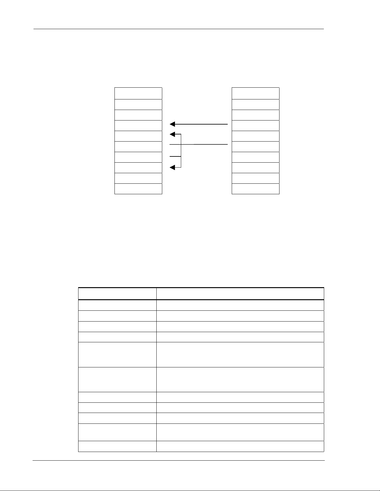
Configuration and Use DART 300 Modem
Cabling
The device supports only a two-pin connection for the Tx and GND signals. The DART 300 must
see asserted RTS and DTR signals. These are both asserted by this cable configuration.
The cable’s DCE end has a male connector and plugs into the modem. The DTE end is a pair of
bare wire connections to be attached to the meter’s terminal block
DCE (male) DTE (bare wire)
1 DCD Not Connected 1 DCD
2 RxD Not Connected 2 RxD
3 TxD 3 TxD
4 DTR 4 DTR
5 GND 5 GND
6 DSR 6 DSR
7 RTS 7 RTS
8 CTS Not Connected 8 CTS
9 RI Not Connected 9 RI
Figure 8-2: Dumb Host Cable Without DTE-DCE Flow Control.
Tx, and GND are straight through (DTE to DCE). The modem’s DSR is tied back to RTS and
DTR to assert these two control signals that meter does not provide. All other signals are
generated by the modem and are left unconnected.
Modem Configuration
The device is used as a client, using Auto-dial on Start-up to force data state at the modem.
Using a terminal application on a PC, set the communication link to 19200,8,N,1 with hardware
flow control on. “AT” is omitted for brevity.
Table 8-2: Sample Configuration – Meter
Command Remarks
+WPNEI=<ip>
+WS174=<n>
+WS173=1
+WS175=0
+WS45=0
+WS179=0
Set the modem’s NEI
Set the side preference
Ensure auto-registration is used. (Default)
Disable Sleep. (Default)
Set UDP PAD. This is required to avoid exposing the modem’s
command processor. A TCP session could be closed by the
remote station.
Ensure the UDP session connec t s immediately, re gardless of
registration. (Default) Along with Auto-dial on Start-up, this
places the modem in data state on power-up and reset.
+WS212=0
S30=0
+WS213=1
+WVFRIEND=<ip.port>
Y
+WS216=1
Page 76 2110212 Rev 1.0
Disable the server side of the UDP stack.
Disable the session timeout. (Default)
Set the Friend List index to 1. (Default)
Set the IP address and port of the monitoring server.
Confirm the setting.
Set to Auto-dial on Start-up to place the modem in data state.
Page 88

User’s Guide UDP/TCP Service
Table 8-2: Sample Configuration – Meter (continued)
Command Remarks
[+WS62=0]
+WS72=0 Disable PAD editing. The binary data may include the <BS>
+WS63=0
+WS70=2
[+WS74=<n>]
&D0
S12=150
+WS60=0
&W
+IPR2400
Optionally disable local PAD echo. RxD is not connected so
this is not required. It may actually be desirable to keep PAD
echo enabled so that a terminal can be simultaneously connected
on-site to the modem’s RxD pin to monitor the data being sent
by the meter.
character as valid data.
Disable the primary forwarding character. The binary stream
has no defined delimiters.
PAD will forward a packet on 0.2 seconds idle from the meter.
This duration is equivalent to 48 characters at 2400 bps.
Optionally set a packet length limit below the default of 1000.
The inter-character timer is the only other forwarding condition.
Ignore DTR. The cable artificially asserts the signal.
Set the TDES guard time to three seconds. The meter sends at
one-second intervals so it will not trigger an escape sequence.
Keeping TDES enabled with a safe guard time allows service
staff a means to connect a terminal, escape data state, and regain
command control of the modem.
Disable TIES. The binary data stream may accidentally contain
this string.
Save the configuration.
Set the modem to 2400 bps to match the meter. The modem
will reset after this command and is ready for field use.
Note: Setting Echo off (E0) and Quiet on (Q1) are not needed in this case, since the modem does
not have a receive (Rx) connection to the meter. These features are left at their default to allow
service personnel to connect a terminal and use the modem.
Using This Configuration
The configuration offered above assumes use of UDP and a fixed IP address and port for the
monitoring server. The DART 300 is placing the data on the network whenever the modem is
powered on and in CDPD coverage. The monitor needs only connect to the network and accept
the packets. There is no means to remotely control the session at the DART 300.
In the event of power disruption at the DART 300, it will automatically recover when it powers-up
or resets. The modem will open the UDP session, register, and send telemetry without any
intervention.
2110212 Rev 1.0 Page 77
Page 89

Configuration and Use DART 300 Modem
Page 78 2110212 Rev 1.0
Page 90

9. SLIP/PPP Service
This section deals with application configuration using SLIP or PPP service mode. SLIP is
covered first in Section 9.1, then PPP in Section 9.2.
NOTE
Users operating the DART 300 in SLIP or PPP mode on a Windows® platform are
encouraged to use the Watcher and WirelessExpert
The software can be downloaded from the Sierra Wireless website at
www.sierrawireless.com
As of this writing, the software is at revision 4.2.1. The DART 300 is not listed as a
modem model within the software’s menus. Use th e SB300 selection. The DART 300
incorporates the SB300 module.
Installation and use of the software is beyond the scope of this document. Consult the
MP200 documentation for information on Watcher. The use of the software is identical
on this product.
The information that follows is targeted at users who cannot use the Watcher software package.
9.1. Serial Line Interface Protocol (SLIP)
.
™
software from Sierra Wireless.
SLIP is one method for encapsulating packet data over dedicated and/or switched serial lines. It is
a useful and reliable way to allow mixes of hosts and routers to communicate with one another in
various combinations.
When operating in SLIP mode, the modem’s internal Packet Assembly / Disassembly (PAD)
services are bypassed and the modem acts as a router passing data between the local host’s
protocol stack, and the CDPD network. All protocol headers are the responsibility of the host as is
the SLIP framing to the packets. The modem will parse the SLIP frame character to distinguish
packets for routing and to identify the data state escape sequence.
This protocol is useful if the host application must have multiple sessions active concurrently.
This situation is not commonly found in telemetry applications. The concept of a session in SLIP
mode is distinct from UDP and TCP PAD modes. From the DART 300 point of view, there is a
SLIP session between the local host and the modem, which does not extend across the CDPD
network to remote clients or servers. To the local host, there is a SLIP session with the modem
and multiple client / server sessions with remote terminals.
Most users of the SLIP mode will also have the ability to use the Watcher enabling software
(available from the Sierra Wireless website). That software will handle configuration and use of
the modem via Windows Dial-Up Networking. This section applies to users who will not be using
a Windows environment on the host device but still want a SLIP connection.
SLIP does not support auto-answer but for cases where the modem’s host device would like to go
to sleep and be advised to wake up when traffic arrives, SLIP does support use of the Ring
Indicator (RI) for incoming messages (enabled by default &I1).
9.1.1. Configuring SLIP Service
This sub-section describes the recommended configuration of the modem as it comes from the
factory for installation in a simple SLIP application. Additional notes are provided regarding
more complex installations.
2110212 Rev 1.0 Page 79
Page 91

Configuration and Use DART 300 Modem
This portion of the configuration is usually performed prior to installation at the application site.
Settings are likely made manually using a terminal program on a PC. It is possible to write a
script to execute the set-up repeatedly on a series of modems but the NEI must be unique on each
modem and as assigned by the CDPD carrier.
(AT is omitted for brevity):
1. Configure the modem’s NEI address and desired channel restrictions:
a. +WPNEI=ip where ip is the NEI address to assign. You do not need leading 0s in the
individual elements of the address. When you press <enter> the modem will respond
with a prompt to confirm the change in the table. The old and new values are both
shown. Press Y (case insensitive) to confirm the change, or
Press N (or any key other than Y) to cancel the command.
The modem will respond with OK if the NEI is in a valid IP form.
This has presumed that you will be entering only one NEI. The default settings of the
NEI indices are left at 1. If more than one NEI account is needed consult Section 7.1
above.
b. +WS174=n where n indicates the application of the channel side (A or B) assigned by
your CDPD provider. Values for n are:
1 – A side preferred,
2 – B side preferred,
3 – A side only,
4 – B side only.
c. Optionally configure desired cellular channel restrictions:
+WPSPNI=n[,n[,…n]] where n is a SPNI value and multiple values are separated by
commas. The list of parameters provided will replace any previous table. You cannot
append entries to an existing table. You may enter up to 10 values in the table. By
entering one or more SPNI values, the SPNI matching feature is automatically enabled.
2. Set the registration parameters and sleep mode as needed:
a. Optionally set manual registration mode. The default from the factory is to use automatic
registration, which is highly recommended. If manual registration is required set
+WS173=0. If this is used, you may also wish to set the Registration Wait Time with
+WS198=n where n is the time in seconds to allow the modem to register. The default
is 30 seconds.
In SLIP mode, the modem will automatically register when requested to go on-line if it
has not auto-registered earlier.
b. Optionally set the modem to use sleep mode. The default has sleep disabled (all settings
to 0).
+WS175=n where n is the idle time in seconds before CDPD sleep is engaged.
+WS31=1 to also apply Logic Sleep; or +WS31=2 to apply logic deep sleep.
3. +WS45=3 selects SLIP service. This is the default from the factory.
4. Optionally set +WS179=1 (Registration Wait Status) to have the modem only report
CONNECT after registration is successful. The modem default (+WS179=0) is to report
CONNECT and enter data state immediately, regardless of the registration status.
5. Set &D2 to ensure the modem will close the session if the DTR signal is lost.
6. Optionally disable the Ring Indicator (RI) si gnal using &I0.
7. Optionally make any settings required by the application for the DTE/DCE interface; items
such as: Echo, the default is on (E1); Quiet, the default is off (Q0); and Verbose, the default
is on (V1).
8. &W to save the configuration.
9. Set the data rate used by the application if it is not 19200 bps. Use +IPR=n where n is the
rate to use. The modem will preserve the new setting and reset after this command. The
modem will then re-start implementing the configuration as made in the steps above.
The modem may now be installed with the target host device.
Page 80 2110212 Rev 1.0
Page 92

User’s Guide SLIP/PPP Service
9.1.2. Using SLIP Service
With a modem configured as noted above (Section 9.1.1), the local host needs to do the following
to connect to the network.
(AT is omitted for brevity):
1. On start-up, either monitor the DART 300 for the OK result code, or check for an assertion of
the CTS control line to indicate the modem is ready.
2. Optionally verify CDPD channel acquisition and registration. You can manage this process
as suits your need. If manual registration is selected, the Dial command can handle the
network registration process using the NEI indexed by the auto-register index. See the AT
Command Reference for details.
3. D (Dial); any parameters are ignored. This command forces the modem to attempt to register
regardless of the setting of auto-registration. The modem will reply with CONNECT and
assert DCD to indicate the transition to data state.
An alternative process is to issue O to go on-line (start the session). This method should only
be used if you know the modem has successfully registered o n t he CDPD network.
The modem is now ready to pass local host packets to the network. Any incoming packets, from
any calling client or responding server, will be passed to the local host. This allows the host to
send and receive packets to and from multiple destinations asynchronously provided the host
application can manage multiple socket connections.
Once in data state , the modem acts as a pipe through which data passes. All PAD and IP protocol
stacks as well as SLIP framing must be implemented within the local host (DTE) system.
Windows Dial-up Networking can provide these services.
9.1.2.1. Transmitting
Data packets received from the host (DTE) are forwarded to the network in 128 byte segments.
They can be buffered on the modem up to 14 segments (1792 bytes). Beyond this, there is local
hardware flow control (RTS/CTS) with the host to prevent overflow (Section 4.4.2 above).
9.1.2.2. Receiving
Incoming data from the network is buffered (up to 14 x 128 bytes) and is passed to the local host
as it arrives. If the modem has been placed in command state but is still in on-line condition,
incoming data will be buffered. There is an automatic remote flow control between the modem
and the CDPD network to prevent data loss when the modem’s buffers are full.
9.1.2.3. Escaping Data State
Two methods of escaping from data state are available: the Escape Sequence (+++) and the use of
the DTR control line. When the modem transitions from data state to command state, the OK
result code is sent to the local host.
Escape Sequence (+++)
To escape data state in SLIP mode, the host can issue the escape sequence <0xC0>+++<0xC0>
to the modem. The hexadecimal value 0xC0 is the SLIP frame character. This means the modem
will be sent a frame containing nothing but the escape code (+++). This is parsed by the modem
as an escape and it will not forward the packet to the network.
The modem will enter command state but remain registered and in on-line condition (the session is
kept open). If data arrives at the modem while the session is open and the modem is in command
state, the data is buffered as described above.
Entering the 0xC0 character from the keyboard is accomplished one of two ways: using the
numeric keypad to enter Alt+0192, or using Character Map, a Windows accessory program.
2110212 Rev 1.0 Page 81
Page 93

Configuration and Use DART 300 Modem
Using DTR to Escape
An alternative to the escape sequence is to pre-set the DTR Options (&D) to either 1 or 2 and then
switch DTR off to escape data state. If the option is set to 1 (&D1), the modem will enter
command state the same as if the escape sequence was issued; it will remain registered with the
current session still open; equivalent to the “+++” escape sequence. If the DTR Option is 2 (&D2)
then the modem will close the session, de-register, and return to command state. Note that if autoregistration is enabled, the modem will switch off DCD (closing the current session) but will
remain registered. If manual registration is used, the modem will be de-registered. Any data
buffered in the modem will be discarded.
Returning to Data State
If the session has been kept open, the host can re-enter data state by issuing the On-line
command (O). The modem will respond with CONNECT and data state is restored.
9.1.3. Closing a SLIP Session
To end a SLIP session, escape data state as described above. If the &D2 DTR option is used then
the session is closed.
If the escape sequence or the &D1 DTR option is used then you must hang-up with eit her H or H1
to close the session. Both of these will close the current session. If the modem is set to manual
registration, it will also be de-registered by both of these commands.
H1 will force de-registration of the modem even if auto-registration is enabled. The modem will
remain de-registered. Although auto-registration remains enabled, the modem will not resume
auto-registration until the register is reset (+WS173=1) or the modem itself resets or power
cycles.
You are advised to issue Z (Reset) following the close of the session to ensure the modem is in a
known state for initiating the next connection.
9.2. Point to Point Protocol (PPP)
This protocol is useful if the host application must have multiple sessions active concurrently.
This situation is not commonly found in telemetry applications. The concept of a session in SLIP
mode is distinct from UDP and TCP PAD modes. From the DART 300 point of view, there is a
PPP session between the local host and the modem, which does not extend across the CDPD
network to remote clients or servers. To the local host, there is a PPP session with the modem and
multiple client / server sessions with remote terminals.
Most users of the PPP mode will also have the ability to use the Watcher enabling software
(available from the Sierra Wireless website). That software will handle configuration and use of
the modem via Windows Dial-Up Networking. This section applies to users who will not be using
a Windows environment on the host device but still want a PPP connection.
9.2.1. Configuring PPP Service
This sub-section describes the recommended configuration of the modem as it comes from the
factory for installation in a simple PPP application.
Page 82 2110212 Rev 1.0
Page 94

User’s Guide SLIP/PPP Service
This portion of the configuration is usually performed prior to installation at the application site.
Settings are likely made manually using a terminal program on a PC. It is possible to write a
script to execute the set-up repeatedly on a series of modems but the NEI must be unique on each
modem and as assigned by the CDPD carrier.
(AT is omitted for brevity):
1. Configure the modem’s NEI address and desired channel restrictions:
a. +WPNEI=ip where ip is the NEI address to assign. You do not need leading 0s in the
individual elements of the address. When you press <enter> the modem will respond
with a prompt to confirm the change in the table. The old and new values are both
shown.
Press Y (case insensitive) to confirm the change, or
Press N (or any key other than Y) to cancel the command.
The modem will respond with OK if the NEI is in a valid IP form.
This has presumed that you will be only entering 1 NEI. The default settings of the NEI
indices are left at 1. If more than one NEI account is needed consult Section 7.1 above.
b. +WS174=n where n indicates the application of the channel side (A or B) assigned by
your CDPD provider. Values for n are:
1 – A side preferred,
2 – B side preferred,
3 – A side only,
4 – B side only.
c. Optionally configure desired cellular channel restrictions:
+WPSPNI=n[,n[,…n]] where n is a SPNI value and multiple values are separated by
commas. The list of parameters provided will replace any previous table. You cannot
append entries to an existing table. You may enter up to 10 values in the table. By
entering one or more SPNI values, the SPNI matching feature is automatically enabled.
2. Set the registration parameters and sleep mode as needed:
a. Optionally set manual registration mode. The default from the factory is to use automatic
registration. If manual registration is required set +WS173=0. If this is used, you may
also wish to set the Registration Wait Time with +WS198=n where n is the time in
seconds to allow the modem to register. The default is 30 seconds.
In PPP mode, the modem will automatically register when requested to go on-line if it
has not auto-registered earlier.
b. Optionally set the modem to use sleep mode. The default has sleep disabled (all settings
to 0).
+WS175=n where n is the idle time in seconds before CDPD sleep is engaged.
+WS31=1 to also apply Logic Sleep; or +WS31=2 to apply logic deep sleep.
3. +WS45=4 selects PPP service. The default from the factory is 3 - SLIP.
4. Optionally set +WS179=1 (Registration Wait Status) to have the modem only report
CONNECT after registration is successful. The modem default (+WS179=0) is to report
CONNECT and enter data state immediately, regardless of the registration status.
5. Set &D2 to ensure the modem will close the session if the DTR signal is lost.
6. Optionally disable the Ring Indicator (RI) si gnal using &I0.
7. Optionally make any settings required by the application for the DTE/DCE interface; items
such as: Echo, the default is on (E1); Quiet, the default is off (Q0); and Verbose, the default
is on (V1).
8. &W to save the configuration.
9. Set the data rate used by the application if it is not 19200 bps. Use +IPR=n where n is the
rate to use. The modem will preserve the new setting and reset after this command. The
modem will then re-start implementing the configuration as made in the steps above.
The modem may now be installed at the application site.
2110212 Rev 1.0 Page 83
Page 95

Configuration and Use DART 300 Modem
9.2.2. Using PPP Service
With a modem configured as noted immediately above, the local host needs to do the following to
connect to the network.
(AT is omitted for brevity):
1. On start-up, either monitor the DART 300 for the OK result code, or check for an assertion of
the CTS control line to indicate the modem is ready.
2. Optionally verify CDPD channel acquisition and registration. You can manage this process
as suits your need. If manual registration is selected, the Dial command can handle the
network registration process using the NEI indexed by the auto-register index. See the AT
Command Reference for details.
3. D (Dial); any parameters are ignored. This command forces the modem to attempt to register
regardless of the setting of auto-registration. This allows the modem to go on-line using just
the one command, but network registration is not guaranteed unless +WS179 was set to 1 in
the configurati on.
The modem will reply with CONNECT at which point PPP is used to negotiate the session
parameters between the modem and local host. If the host does not handshake the PPP
negotiation promptly, the modem will drop the connection and revert to command state with
the OK result code.
An alternative process is to issue O to go on-line (start the session). This should only be used
if you know the modem has successfully registered on the CDPD network.
The modem is now operating under PPP control to pass host packets to the network. Any
incoming packets, from any calling client or responding server, will be passed to the local host.
This allows the host to send and receive packets to and from multiple destinations asynchronously
provided the host can manage multiple socket connections.
Once in data state , the modem acts as a pipe through which data passes. All PAD and IP protocol
stacks as well as PPP framing must be implemented on the local host (DTE) system. Windows
Dial-up Networking can provide these services.
9.2.2.1. Transmitting
Data packets received from the local host (DTE) are forwarded to the network in 128 byte
segments. They can be buffered on the modem up to 14 segments (1792 bytes). Beyond this,
there is local hardware flow control (RTS/CTS) with the host to prevent overflow.
9.2.2.2. Receiving
Incoming data from the network is buffered (up to 14 x 128 bytes) and is passed to the local host
as it arrives. If the modem has been placed in command state but is still in on-line condition,
incoming data will be buffered. There is an automatic remote flow control between the modem
and the network to prevent overflow when the modem’s buffers are full.
9.2.3. Closing a PPP Session
To end a PPP session, escape data state via PPP or by using DTR in conjunction with the &D2
DTR option.
If the PPP escape sequence or the &D1 DTR option is used then you must hang-up with either H
or H1 to close the session. Both of these will close the current session. If the modem is set to
manual registration, it will also be de-registered by both of these commands.
H1 will force de-registration of the modem even if auto-registration is enabled. The modem will
remain de-registered. Although auto-registration remains enabled, the modem will not resume
auto-registration until the register is reset (+WS173=1) or the modem itself resets or power
cycles.
Page 84 2110212 Rev 1.0
Page 96

User’s Guide SLIP/PPP Service
You are advised to issue Z (Reset) following the close of the session to ensure the modem is in a
known state for initiating the next connection.
2110212 Rev 1.0 Page 85
Page 97

Configuration and Use DART 300 Modem
Page 86 2110212 Rev 1.0
Page 98
10. Device Attachment
This section describes the connections to the unit for power, serial data, and antenna / booster.
The RS-232 serial interface to the DART is covered along with what a null modem is, and how to
determine if one is required.
10.1. Antenna Connection
The DART 300 modem uses standard mobile cellular radio signals. Any standard 800 MHz
cellular antenna of good quality with a male TNC connector and 50 Ohms impedance should serve
well. A suitable antenna is available from Sierra Wireless (part number 6000065).
CAUTION
The combination of cable loss and antenna gain must yield an overall system gain not
exceeding 0 dB. The transmitter output of 0.6 Watt is delivered at the connector. This
is the FCC regulated limit of a Class III device.
Installation
Antenna performance is subject to the following guidelines:
Location – Locate the antenna as far away from personnel as possible to minimize signal
blocking. For optimum reception in indoor fixed location applications, position the antenna above
the height of personnel and nearby equipment or structures. If used indoors, locate the antenna as
close to a window as possible. In mobile applications, locate the antenna outside and away from
or above any portion of the vehicle body that can block the RF signals.
Cabling – Select a low loss, high quality, 50 Ohm, coaxial cable with the appropriate connectors.
The cable can be any length, but lengths greater than 4 meters (13.1 feet) increase cable loss and
offset the antenna’s nominal gain. If longer length cables a re required, use a heavier wire gauge to
reduce the dB loss/m and to minimize the effect of the cable loss on antenna gain. See the caution
above regarding FCC requirements for cable loss.
CAUTION
For outdoor fixed installations ground the antenna cable using an antenna discharge
unit to prevent damage to the modem and the attached equipment.
Ground Plane – For installations where a good antenna ground plane (metal surface) is not
available, use a non-ground plane type of antenna to help maximize signal reception.
Proximity to Other Antennas – In general, do not locate the DART 300 modem antenna closer
than 1.5 meters (5 feet) to another antenna. In certain cases even more separation is required. In
many vehicular applications, there are high-power two-way voice transmitters used and usually
the antenna mounting locations are not adequately separated. The effect of the interference from
two-way transmitters varies from slowing down response times to blocking modem transmission.
In this situation, separate the antennas as far as possible and then do a test with the voice system
also being used. If the DART 300 works satisfactorily you do not have an interference problem.
If it does not work properly, then use filtering on the two-way output, the DART 300 antenna
input, or both. The calculation to determine the required filtering is not trivial and usually requires
2110212 Rev 1.0 Page 87
Page 99
Installation DART 300 Modem
a RF engineer. However, if you do not have the option to do a test first, this analytical approach is
your only option.
10.2. 3-Watt Class I Booster Operation
The DART 300 modem is capable of supporting the Sierra Wireless AirBooster 350 RF Amplifier.
This device boosts the 600 mW (Class III) output of the modem to a maximum 3W (Class I)
output.
The DART 300 modem can automatically detect the presence of the AirBooster 350 amplifier.
Due to the hardware required to support this auto-detection, any testing of the DART 300 RF
output must be done with care.
CAUTION
In cases where the antenna output is to be connected to test equipment, DC blocks must
be used on the antenna output to protect the test equipment and avoid false booster
detection.
The amplifier is an “intelligent” booster in that it does not simply apply a fixed gain to a varying
input RF level like a linear amplifier would. Instead, the AirBooster amplifier takes a constant RF
level from the CDPD device and applies as much gain as the CDPD system allows at that moment.
In order to achieve this there is a control signal used between the modem and the AirBooster 350.
This signaling is used to enable the RF amplifier and to control its output level. Without the
control signal (such as plugging a non-Sierra Wireless product into the booster) the
AirBooster 350 will shut off the RF amplifier and block the RF output. The receive side of the
antenna will function normally but transmission will be seriously impaired.
The DART 300 uses a control register at +WS214 (Booster Support) to enable or disable the use
of the control signal. This register is enabled (set to 1) by default. If it is disabled and the
AirBooster 350 is connected, the modem will suffer the same transmission impairment as any
other non-supported device.
10.2.1. Connection
A custom connection cable (Male TNC to Male SMA) is used. Due to the variation in required
cable lengths and connector types that may be needed between the booster and the host CDPD
device, there is no host cable in the AirBooster 350 RF amplifier package. These cables are
ordered separately from Sierra Wireless (part number 2000096).
The steps involved in the connection are:
1. Ensure both the modem and the amplifier are powered off.
2. Connect the TNC connector to the DART 300 antenna connector.
3. Thread the cable between the DART 300 and the AirBooster 350 amplifier.
4. Attach the SMA connector to the AirBooster 350 MODEM connector. Tighten firmly by
hand; do not use tools.
5. Apply power to the AirBooster amplifier. The AirBooster power indicator will light.
6. Apply power to the DART 300. The AirBooster amplifier’s status indicator will light when
the modem has detected the amplifier.
Page 88 2110212 Rev 1.0
Page 100

User’s Guide Device Attachment
10.3. The Serial Connector
When testing the modem using a PC terminal, the cable is a standard RS-232 9-pin connection as
outlined below:
Pin Signal Direction
1 DCD – Data Carrier Detect DCE ! DTE
2 RxD – Receive Data DCE ! DTE
3 TxD – Transmit Data DCE " DTE
4 DTR – Data Terminal Ready DCE " DTE
5 GND – Signal Ground Common
6 DSR – Data Set Ready DCE ! DTE
7 RTS – Request to Send DCE " DTE
8 CTS – Clear to Send DCE ! DTE
9 RI – Ring Indicator DCE ! DTE
The pins are arranged in the connector as noted below:
Figure 10-1: Pinouts for Female DB-9 Connector (DCE).
10.3.1. Null-Modem Connection
When connecting the DART 300 to a local host device, there may be a need to use a “nullmodem” type of connection. The RS-232 interface specification was intended to standardize the
method that computers and terminals (DTE) used to communicate remotely over telephone lines
(DCE). The popularization of RS-232 serial communications resulted in many different types of
equipment, besides modems, that employ the DCE standard. Many manufacturers expect devices
to connect directly to DTE equipment (usually, PCs). Consequently, devices are designed with a
DCE interface, so a standard RS-232 cable meets the cabling requirements.
If the local device is designed for connection to a DTE terminal, it is already designed to be a DCE
device. Since the DART 300 is also a DCE device, the connections must be crossed over to
enable throughput. To id entify this proble m, c onnect a PC di rectly to the loc al host device and
establish communication. If communication is established, the device uses a DCE interface and
the null-modem cable will be required to connect to the DART 300 modem.
12345
6789
Null modem adapters are available that look like a RS-232 gender-changer. These adapters are
available from electronics stores and are well suited for application development. Null modem
cables can be ordered from cable suppliers and electronic stores. These are better suited for field
deployment because the cables eliminate the extra part and potential for failure that an adapter
would introduce.
2110212 Rev 1.0 Page 89
 Loading...