

Page 1

AirPrime MiniCard
MC73xx/8805
AT Command Reference
4114486
Rev. 1
Page 2

Page 3

Preface
Important Notice
Safety and Hazards
Due to the nature of wireless communications, transmission and reception of data
can never be guaranteed. Data may be delayed, corrupted (i.e., have errors) or be
totally lost. Although significant delays or losses of data are rare when wireless
devices such as the Sierra Wireless modem are used in a normal manner with a
well-constructed network, the Sierra Wireless modem should not be used in
situations where failure to transmit or receive data could result in damage of any
kind to the user or any other party, including but not limited to personal injury,
death, or loss of property. Sierra Wireless accepts no responsibility for damages
of any kind resulting from delays or errors in data transmitted or received using
the Sierra Wireless modem, or for failure of the Sierra Wireless modem to
transmit or receive such data.
Do not operate the Sierra Wireless modem in areas where blasting is in progress,
where explosive atmospheres may be present, near medical equipment, near life
support equipment, or any equipment which may be susceptible to any form of
radio interference. In such areas, the Sierra Wireless modem MUST BE
POWERED OFF. The Sierra Wireless modem can transmit signals that could
interfere with this equipment.
Do not operate the Sierra Wireless modem in any aircraft, whether the aircraft is
on the ground or in flight. In aircraft, the Sierra Wireless modem MUST BE
POWERED OFF. When operating, the Sierra Wireless modem can transmit
signals that could interfere with various onboard systems.
Limitation of Liability
Note: Some airlines may permit the use of cellular phones while the aircraft is on the
ground and the door is open. Sierra Wireless modems may be used at this time.
The driver or operator of any vehicle should not operate the Sierra Wireless
modem while in control of a vehicle. Doing so will detract from the driver or
operator's control and operation of that vehicle. In some states and provinces,
operating such communications devices while in control of a vehicle is an offence.
The information in this manual is subject to change without notice and does not
represent a commitment on the part of Sierra Wireless. SIERRA WIRELESS AND
ITS AFFILIATES SPECIFICALLY DISCLAIM LIABILITY FOR ANY AND ALL
DIRECT, INDIRECT, SPECIAL, GENERAL, INCIDENTAL, CONSEQUENTIAL,
PUNITIVE OR EXEMPLARY DAMAGES INCLUDING, BUT NOT LIMITED TO,
LOSS OF PROFITS OR REVENUE OR ANTICIPATED PROFITS OR REVENUE
ARISING OUT OF THE USE OR INABILITY TO USE ANY SIERRA WIRELESS
PRODUCT, EVEN IF SIERRA WIRELESS AND/OR ITS AFFILIATES HAS BEEN
ADVISED OF THE POSSIBILITY OF SUCH DAMAGES OR THEY ARE
FORESEEABLE OR FOR CLAIMS BY ANY THIRD PARTY.
Notwithstanding the foregoing, in no event shall Sierra Wireless and/or its
affiliates aggregate liability arising under or in connection with the Sierra Wireless
product, regardless of the number of events, occurrences, or claims giving rise to
liability, be in excess of the price paid by the purchaser for the Sierra Wireless
product.
Rev. 1 Sep.13 Proprietary and Confidential 3
Page 4

AirPrime MC73xx/8805 AT Command Reference
Patents This product may contain technology developed by or for Sierra Wireless Inc. This
®
product includes technology licensed from QUALCOMM
. This product is
manufactured or sold by Sierra Wireless Inc. or its affiliates under one or more
patents licensed from InterDigital Group and MMP Portfolio Licensing.
Copyright © 2013 Sierra Wireless. All rights reserved.
Trademarks Sierra Wireless
are trademarks of Sierra Wireless.
AirCard
Inc.
Windows
Corporation.
Macintosh
the U.S. and other countries.
QUALCOMM
under license.
Other trademarks are the property of their respective owners.
®
®
, AirPrime®, AirLink®, AirVantage® and the Sierra Wireless logo
, Watcher® and NETGEAR® are registered trademarks of NETGEAR,
®
and Windows Vista® are registered trademarks of Microsoft
®
and Mac OS® are registered trademarks of Apple Inc., registered in
®
is a registered trademark of QUALCOMM Incorporated. Used
Contact Information
Sales Desk: Phone: 1-604-232-1488
Hours: 8:00
E-mail: sales@sierrawireless.com
Post: Sierra Wireless
13811 Wireless Way
Richmond, BC
Canada V6V 3A4
AM to 5:00 PM Pacific Time
Fax: 1-604-231-1109
Web: www.sierrawireless.com
Consult our website for up-to-date product descriptions, documentation,
application notes, firmware upgrades, troubleshooting tips, and press releases:
www.sierrawireless.com
Revision History
Revision
number
1
4 Proprietary and Confidential 4114486
Release date Changes
ep 2013 • Created document
S
Page 5

Contents
About This Guide . . . . . . . . . . . . . . . . . . . . . . . . . . . . . . . . . . . . . . . . . . . . . . . .9
Introduction. . . . . . . . . . . . . . . . . . . . . . . . . . . . . . . . . . . . . . . . . . . . . . . . . . . 9
Command access. . . . . . . . . . . . . . . . . . . . . . . . . . . . . . . . . . . . . . . . . . . . . . 9
Command timing . . . . . . . . . . . . . . . . . . . . . . . . . . . . . . . . . . . . . . . . . . . . . . 9
Interval timing . . . . . . . . . . . . . . . . . . . . . . . . . . . . . . . . . . . . . . . . . . . . . . .9
Escape sequence guard time . . . . . . . . . . . . . . . . . . . . . . . . . . . . . . . . .10
Result codes. . . . . . . . . . . . . . . . . . . . . . . . . . . . . . . . . . . . . . . . . . . . . . . . . 10
References. . . . . . . . . . . . . . . . . . . . . . . . . . . . . . . . . . . . . . . . . . . . . . . . . . 10
Terminology and acronyms . . . . . . . . . . . . . . . . . . . . . . . . . . . . . . . . . . . . . 10
Current firmware versions . . . . . . . . . . . . . . . . . . . . . . . . . . . . . . . . . . . . . . 10
Version . . . . . . . . . . . . . . . . . . . . . . . . . . . . . . . . . . . . . . . . . . . . . . . . . . .10
Upgrading . . . . . . . . . . . . . . . . . . . . . . . . . . . . . . . . . . . . . . . . . . . . . . . .10
Document structure . . . . . . . . . . . . . . . . . . . . . . . . . . . . . . . . . . . . . . . . . . . 10
Conventions . . . . . . . . . . . . . . . . . . . . . . . . . . . . . . . . . . . . . . . . . . . . . . . . . 16
AT Password Commands . . . . . . . . . . . . . . . . . . . . . . . . . . . . . . . . . . . . . . . .17
Introduction. . . . . . . . . . . . . . . . . . . . . . . . . . . . . . . . . . . . . . . . . . . . . . . . . . 17
Command summary. . . . . . . . . . . . . . . . . . . . . . . . . . . . . . . . . . . . . . . . . . . 17
Command reference. . . . . . . . . . . . . . . . . . . . . . . . . . . . . . . . . . . . . . . . . . . 18
Modem Status, Customization, and Reset Commands . . . . . . . . . . . . . . . .19
Introduction. . . . . . . . . . . . . . . . . . . . . . . . . . . . . . . . . . . . . . . . . . . . . . . . . . 19
Command summary. . . . . . . . . . . . . . . . . . . . . . . . . . . . . . . . . . . . . . . . . . . 19
Command reference. . . . . . . . . . . . . . . . . . . . . . . . . . . . . . . . . . . . . . . . . . . 21
Diagnostic Commands . . . . . . . . . . . . . . . . . . . . . . . . . . . . . . . . . . . . . . . . . . .53
Introduction. . . . . . . . . . . . . . . . . . . . . . . . . . . . . . . . . . . . . . . . . . . . . . . . . . 53
Command summary. . . . . . . . . . . . . . . . . . . . . . . . . . . . . . . . . . . . . . . . . . . 53
Command reference. . . . . . . . . . . . . . . . . . . . . . . . . . . . . . . . . . . . . . . . . . . 54
Rev. 1 Sep.13 Proprietary and Confidential 5
Page 6

AirPrime MC73xx/8805 AT Command Reference
Test Commands . . . . . . . . . . . . . . . . . . . . . . . . . . . . . . . . . . . . . . . . . . . . . . . . 57
Introduction . . . . . . . . . . . . . . . . . . . . . . . . . . . . . . . . . . . . . . . . . . . . . . . . . 57
Command summary . . . . . . . . . . . . . . . . . . . . . . . . . . . . . . . . . . . . . . . . . . 58
Command reference . . . . . . . . . . . . . . . . . . . . . . . . . . . . . . . . . . . . . . . . . . 60
Memory Management Commands . . . . . . . . . . . . . . . . . . . . . . . . . . . . . . . . . 85
Introduction . . . . . . . . . . . . . . . . . . . . . . . . . . . . . . . . . . . . . . . . . . . . . . . . . 85
Command summary . . . . . . . . . . . . . . . . . . . . . . . . . . . . . . . . . . . . . . . . . . 85
Command reference . . . . . . . . . . . . . . . . . . . . . . . . . . . . . . . . . . . . . . . . . . 86
GPS Commands . . . . . . . . . . . . . . . . . . . . . . . . . . . . . . . . . . . . . . . . . . . . . . . . 87
Introduction . . . . . . . . . . . . . . . . . . . . . . . . . . . . . . . . . . . . . . . . . . . . . . . . . 87
Command summary . . . . . . . . . . . . . . . . . . . . . . . . . . . . . . . . . . . . . . . . . . 87
Command reference . . . . . . . . . . . . . . . . . . . . . . . . . . . . . . . . . . . . . . . . . . 89
Error codes . . . . . . . . . . . . . . . . . . . . . . . . . . . . . . . . . . . . . . . . . . . . . . 114
SIM Commands . . . . . . . . . . . . . . . . . . . . . . . . . . . . . . . . . . . . . . . . . . . . . . . 117
Introduction . . . . . . . . . . . . . . . . . . . . . . . . . . . . . . . . . . . . . . . . . . . . . . . . 117
Command summary . . . . . . . . . . . . . . . . . . . . . . . . . . . . . . . . . . . . . . . . . 117
Command reference . . . . . . . . . . . . . . . . . . . . . . . . . . . . . . . . . . . . . . . . . 118
OMA-DM Commands . . . . . . . . . . . . . . . . . . . . . . . . . . . . . . . . . . . . . . . . . . . 119
Introduction . . . . . . . . . . . . . . . . . . . . . . . . . . . . . . . . . . . . . . . . . . . . . . . . 119
Command summary . . . . . . . . . . . . . . . . . . . . . . . . . . . . . . . . . . . . . . . . . 119
Command reference . . . . . . . . . . . . . . . . . . . . . . . . . . . . . . . . . . . . . . . . . 120
SAR Backoff and Thermal Control Commands . . . . . . . . . . . . . . . . . . . . . . 127
Introduction . . . . . . . . . . . . . . . . . . . . . . . . . . . . . . . . . . . . . . . . . . . . . . . . 127
Command summary . . . . . . . . . . . . . . . . . . . . . . . . . . . . . . . . . . . . . . . . . 127
Command reference . . . . . . . . . . . . . . . . . . . . . . . . . . . . . . . . . . . . . . . . . 128
6 Proprietary and Confidential 4114486
Page 7

Contents
Supported GSM/WCDMA AT Commands . . . . . . . . . . . . . . . . . . . . . . . . . .131
HSDPA/ HSUPA Categories . . . . . . . . . . . . . . . . . . . . . . . . . . . . . . . . . . . . . 141
Band Definitions . . . . . . . . . . . . . . . . . . . . . . . . . . . . . . . . . . . . . . . . . . . . . . 143
ASCII Table. . . . . . . . . . . . . . . . . . . . . . . . . . . . . . . . . . . . . . . . . . . . . . . . . . . 145
Index (AT commands). . . . . . . . . . . . . . . . . . . . . . . . . . . . . . . . . . . . . . . . . . 147
Index . . . . . . . . . . . . . . . . . . . . . . . . . . . . . . . . . . . . . . . . . . . . . . . . . . . . . . . . 153
Rev. 1 Sep.13 Proprietary and Confidential 7
Page 8

AirPrime MC73xx/8805 AT Command Reference
8 Proprietary and Confidential 4114486
Page 9

1: About This Guide
Introduction
This document describes supported standard and proprietary AT
commands available for Sierra Wireless AirPrime™ products, and
provides details where commands vary from the standards. These
commands are intended for use by OEMs, and are supplemental to
the standard AT commands for GSM devices defined by the 3GPP
(3rd Generation Partnership Project) in TS 27.007 AT command set
for User Equipment (UE) and TS 27.005 Use of Data Terminal
Equipment—Data Circuit terminating Equipment (DTE-DCE)
interface for Short Message Service (SMS) and Cell Broadcast
Service (BSE).
1
Note: When designing applications that use these AT commands, use
Watcher
ensure proper use of command groups. For questions or concerns relating to
command implementation, please contact your Sierra Wireless account
representative.
®
or other Sierra Wireless applications as functionality templates to
Command access
Most commands in this reference are password-protected. To use
these commands, you must enter the correct password using
AT !ENTERCND on page 18. Once the password is entered, all
commands are available and remain available until the modem is
reset or powered off and on.
The password assigned to
and is configured onto the modem during manufacture. If you do not
know your password, contact your Sierra Wireless Account Manager.
AT!ENTERCND is unique to each carrier
Command timing
Interval timing
Some commands require time to process before additional
commands are entered. For example, the modem returns OK when it
receives
this, the modem returns an error.
When building automated test scripts, ensure that sufficient delays
are embedded, where necessary, to avoid these errors.
Rev. 1 Sep.13 Proprietary and Confidential 9
AT!DAFTMACT. If AT!DASBAND is received too soon after
Page 10

AirPrime MC73xx/8805 AT Command Reference
Escape sequence guard time
The AT escape sequence “+++” requires a guard time of 1.0 seconds before and
after it is used.
Result codes
Result codes are not shown in the command tables unless special conditions
apply. Generally the result code OK is returned when the command has been
executed. ERROR may be returned if parameters are out of range, and is
returned if the command is not recognized or is not permitted in the current state
or condition of the modem.
References
This guide covers the command sets used by OEMs, designers and testers of
Sierra Wireless AirPrime products, plus general operational use commands.
You may also want to consult the other documents available on our website at
www.sierrawireless.com.
Terminology and acronyms
This document makes wide use of acronyms that are in common use in data
communications and cellular technology.
Current firmware versions
Version
To determine your firmware revision, enter the identification command AT+GMR.
Upgrading
If your modem firmware is an earlier version, you can acquire updated firmware
by contacting your account manager.
Document structure
This document describes the proprietary commands listed in the tables below—
each table corresponds to a specific chapter.
10 Proprietary and Confidential 4114486
Page 11

About This Guide
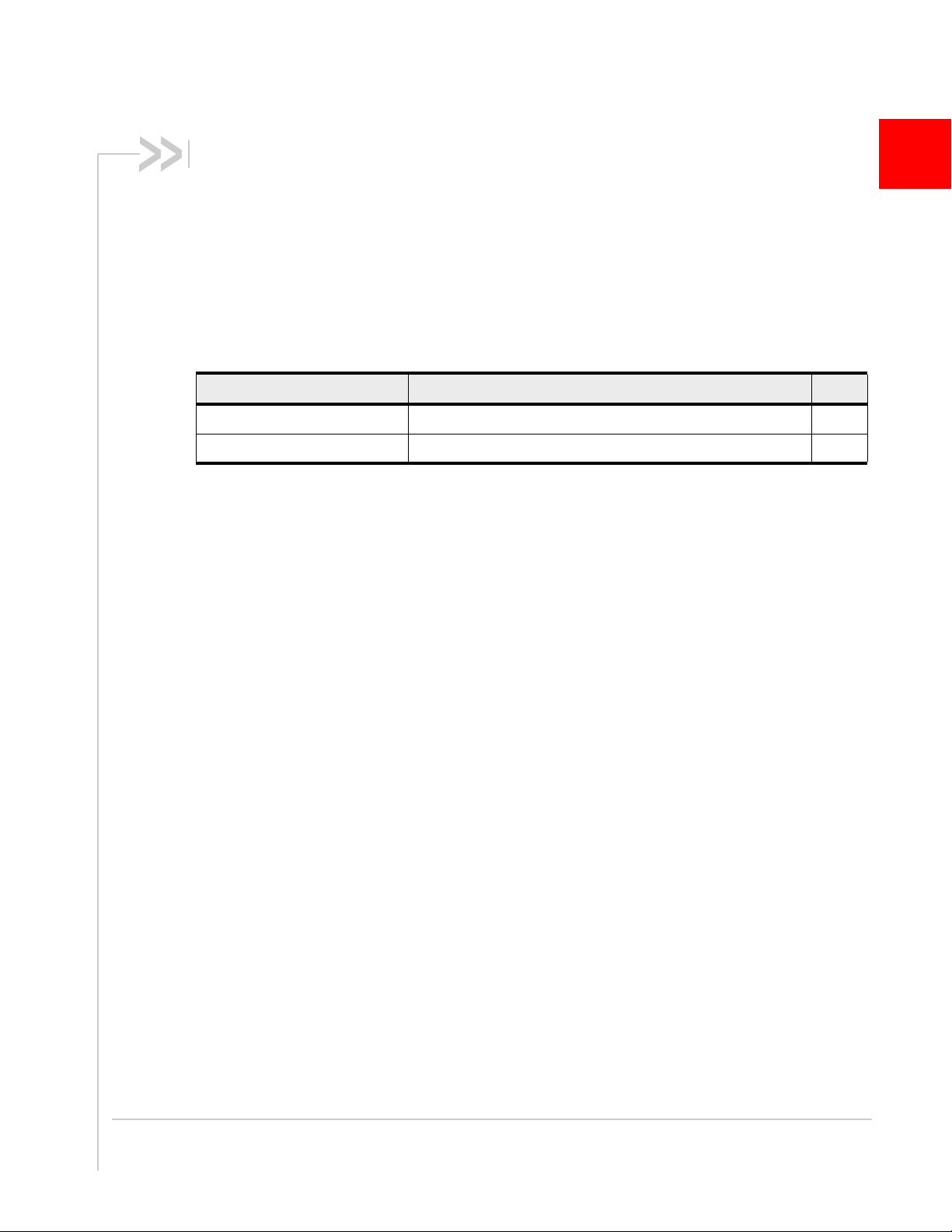
AT Password Commands — Commands used to enable access to password-
protected AT commands and to set the AT command password.
Table 1-1: AT password commands
Command Description Page
!ENTERCND Enable access to password-protected commands 18
!SETCND Set AT command password 18
Modem Status, Customization, and Reset Commands— Commands used to
determine modem status, adjust customization settings, and reset the modem.
Table 1-2: Modem status commands
Command Description Page
!ANTSEL Set/query external antenna select configuration 21
!BAND Select/return frequency band set 22
!BOOTHOLD Reset modem and wait in bootloader for firmware download 23
!CUSTOM Set/return customization settings 24
!DARPEN Enable/disable DARP for SAIC 28
!DTMEN Enable/disable Dual Transfer Mode stack functionality 29
!EDAEN Configure protocol stack for EDA 29
!GCFEN Enable/disable GCF test mode 30
!GCFUIMTYPE Set /return current SIM type 30
!GETBAND Return the current active band 31
!GETRAT Return the current active radio access technology (RAT) 31
!GOBIIMPREF Query/set Gobi Image Management preferences 32
!GRESET Reset the modem 33
!GSTATUS Return operational status 33
!LTENAS Configure LTE NAS settings 34
!NASREL Set/report supported NAS release compliance version 35
!NVENCRYPTIMEI Write unencrypted IMEI to modem 36
!NVNSCODE Return Network Subset codes 37
!NVPLMN Provision PLMN list for Network Personalization locking 38
!NVSPCODE Provision Network Service Provider code list 38
!PACKAGE Return package version string 39
!PCINFO Return power control status information 39
!PCOFFEN Set/return Power Off Enable state 40
Rev. 1 Sep.13 Proprietary and Confidential 11
Page 12

AirPrime MC73xx/8805 AT Command Reference
Table 1-2: Modem status commands (Continued)
Command Description Page
!PCTEMP Return current temperature information 40
!PCTEMPLIMITS Set/report temperature state limit values 41
!PCVOLT Return current power supply voltage information 42
!PCVOLTLIMITS Set/report power supply voltage state limit values 43
!POWERDOWN Power down system 44
!PRIID Set/report module PRI part number and revision 44
!REL Set/report active protocol/revision 45
!RESET Reset modem 45
!SELACQ Select RAT acquisition order 46
!SELMODE Set/return current service domain 47
!SIMRSTC Set/report SIM refresh reset notification state 47
!UDINFO Return informatio n from active USB descriptor 48
!UDPID Set/report product ID in USB descriptor 49
!UDUSBCOMP Set/report USB interface configuration 50
&V Return operating mode AT configuration parameters 51
Diagnostic Commands— Commands used to select frequency bands and
diagnose problems.
Table 1-3: Diagnostic commands
Command Description Page
!BCFWUPDATESTATUS Report status of most recent firmware update attempt 54
!ERR Display diagnostic information 55
!RXDEN Enable/disable WCDMA/LTE receive diversity 56
Test Commands —Commands required to place the modem in particular modes
of operation, test host connectivity, and to configure the transmitters and receivers
for test measurements.
Table 1-4: Test commands
Command Description Page
!DAFTMACT Put modem into Factory Test Mode 60
!DAFTMDEACT Put modem into online mode from Factory Test Mode 60
!DAGGAVGRSSI Return averaged RSSI value in dBm (GSM only) 61
!DAGGRSSI Return the RSSI value in dBm (GSM only) 61
12 Proprietary and Confidential 4114486
Page 13

About This Guide
Table 1-4: Test commands (Continued)
Command Description Page
!DAGGRSSIRAW Return raw RSSI value 62
!DAGINFO Return GSM mode RF information (GSM only) 63
!DAGSLOCK Return synthesizer lock state 64
!DAGSRXBURST Set GSM receiver to burst mode 64
!DAGSRXCONT Set GSM receiver continuously on 65
!DAGSTXBURST Set GSM transmitter to burst mode 65
!DAGSTXFRAME Set GSM Tx frame structure 66
!DALGAVGAGC Return averaged Rx AGC value (LTE only) 67
!DALGRXAGC Return Rx AGC value (LTE only) 68
!DALGTXAGC Return Tx AGC value and transmitter parameters (LTE only) 69
!DALSPARANGE Set LTE PA range (LTE only) 70
!DALSRXBW Set LTE Rx bandwidth (LTE only) 71
!DALSTXBW Set LTE Tx bandwidth (LTE only) 71
!DALSTXINDEX Set LTE Tx gain index (LTE only) 72
!DALSWAVEFORM Set LTE TX waveform (LTE only) 72
!DAOFFLINE Place mode m offline 73
!DASBAND Set frequency band 73
!DASCHAN Set modem chann el (frequency) 74
!DASLNAGAIN Set LNA gain state 75
!DASPDM Set PDM value 76
!DASTXOFF Turn Tx PA o ff 76
!DASTXON Turn Tx PA on 77
!DAWGAVGAGC Return averaged Rx AGC value (WCDMA only) 77
!DAWGRXAGC Return Rx AGC value (WCDMA only) 78
!DAWINFO Return WCDMA mode RF information (WCDMA only) 79
!DAWSCONFIGRX Set WCDMA receiver to factory calibration settings 80
!DAWSPARANGE Set PA range state machine 81
!DAWSSCHAIN Enable secondary receive chain (WCDMA only) 81
!DAWSCHAINTCM Place receive chain in test call mode (WCDMA only) 82
!DAWSTXCW Set waveform used by the transmitter 82
!DAWSTXPWR Set desired Tx power level (WCDMA mode only) 83
Rev. 1 Sep.13 Proprietary and Confidential 13
Page 14

AirPrime MC73xx/8805 AT Command Reference
Table 1-4: Test commands (Continued)
Command Description Page
!GCDUMP Disp lay crash dump data 83
!IMSTESTMODE Enable/disable IMS test mode 84
Memory Management Commands— Commands that control the data stored in
non-volatile memory of the modem.
Table 1-5: Memory management commands
Command Description Page
!NVDEF Reset non-volatile memory 86
!NVRESTORE Restore backup data 86
GPS Commands—Supported on GPS-enabled modems only.
Table 1-6: GPS commands
Command Description Page
!GPSAUTOSTART Configure GPS auto-sta r t features 89
!GPSCLRASSIST Clear specific GPS assistance data 90
!GPSEND End an active session 91
!GPSFIX Initiate GPS position fix 92
!GPSKEEPWARM Configure Keep Warm functionality 93
!GPSLBSAPN Set GPS LBS APNs 94
!GPSLOC Return last known location of the modem 96
!GPSMOMETHOD Set/report GPS MO method 97
!GPSMTLRSETTINGS Set/report MT location request settings 98
!GPSNIQOSTIME Set/report GPS QoS timeout period for network-initialized fixes 98
!GPSNMEA Enable/disable NMEA streaming 99
!GPSNMEACONFIG Enable and set NMEA data output rate 99
!GPSNMEASENTENCE Set/report NMEA sentence type 100
!GPSPORTID Set/report port ID to use over TCP/IP 101
!GPSPOSMODE Configure support for GPS positioning modes 102
!GPSSATINFO Request satellite information 103
!GPSSTATUS Request current status of a position fix session 104
!GPSSUPLURL Set/report SUPL server URL 105
!GPSSUPLVER Set/report SUPL server version 105
14 Proprietary and Confidential 4114486
Page 15

About This Guide
Table 1-6: GPS commands (Continued)
Command Description Page
!GPSTRACK Initiate local tracking (multiple fix) session 106
!GPSTRANSSEC Control GPS transport security 107
!GPSXTRAAPN Set GPS XTRA APNs 108
!GPSXTRADATAENABLE Set/report GPS XTRA settings 109
!GPSXTRADATAURL Set/report GPS XTRA data server URLs 110
!GPSXTRAINITDNLD Initiate gpsOneXTRA data download and inject operation 110
!GPSXTRASTATUS Return current status of gpsOneXTRA 111
!GPSXTRATIME Inject GPS or UTC time into gpsOneXTRA system 112
!GPSXTRATIMEENABLE Set/report GPS XTRA time settings 113
!GPSXTRATIMEURL Set/report GPS XTRA SNTP server URLs 114
SIM Commands— Commands used to communicate with an installed (U)SIM.
Table 1-7: GPS commands
Command Description Page
!ICCID Return (U)SIM card’s ICCID 118
OMA-DM Commands—Commands used to configure DM (Device Management)
accounts, sessions, and host–device–server interactions.
Table 1-8: OMA-DM commands
Command Description Page
!IDSAUTOFOTA Configure automatic settings for FOTA updates 120
!IDSAUTOSDM Configure Subscriber Device Management response to server
request
!IDSCONFIGACC Configure DM account authentication mode and XML format 122
!IDSCREATEACC Enter DM account credentials 123
!IDSDFLTACC Set DM account to use for device-initiated sessions 124
!IDSPID Set profile ID for DM data connection types 124
!IDSROAM Configure DM client roaming support 125
!IDSSUPPORT Configure DM sessions 126
121
Rev. 1 Sep.13 Proprietary and Confidential 15
Page 16

AirPrime MC73xx/8805 AT Command Reference
SAR Backoff and Thermal Control Commands—Commands used to configure
SAR options, and thermal mitigation algorithm parameters and limits.
Table 1-9: SAR backoff and thermal control commands
Command Description Page
!MAXPWR Set/report maximum Tx power 128
!SARINTGPIOMODE Set/report default pull mode for SAR interrupt GPIOs 129
Conventions
The following format conventions are used in this reference:
Character codes or keystrokes that are described with words or standard
abbreviations are shown within angle brackets using a different font, such as
<CR> for Carriage Return and <space> for a blank space character.
Numeric values are decimal unless prefixed as noted below.
Hexadecimal values are shown with a prefix of 0x, i.e. in the form 0x3D.
Binary values are shown with a prefix of 0b, i.e. in the form 0b00111101.
Command and register syntax is noted using an alternate font:
The leading “
commands except as noted in the reference tables.
Characters that are required are shown in uppercase; parameters are noted in
lowercase. Required parameters are enclosed in angle brackets (
optional parameters are enclosed within square brackets (
not to be included in the command string.
Commands are presented in table format. Each chapter covers the commands
related to that subject and presents a summary table to help you locate a needed
command. Commands are in ASCII alphabetical order in the body of each
chapter.
Any default settings are noted in the command tables. Note that these are the
factory default settings and not the default parameter value assumed if no
parameter is specified.
Result Code This is a numeric or text code that is returned after all commands
(except resets)—text codes are returned if verbose responses are enabled. Only
one result code is returned for a command line regardless of the number of
individual commands contained on the line.
Response This term indicates a response from the modem that is issued prior to
a result code. Reading registers or issuing commands that report information will
provide a response followed by a result code unless the command generates an
error.
AT” characters are not shown but must be included before all
!CHAN=<c>[,b].
<n>) while
[x]). The brackets are
Responses and result codes from the modem, or host system software prompts,
are shown in this font:
CONNECT 14400
16 Proprietary and Confidential 4114486
Page 17
2: AT Password Commands
Introduction
AT commands described in this document are password-protected.
This chapter describes how to enter and change the password.
Command summary
Ta bl e 2 - 1 on page 17 lists the commands described in this chapter.
Table 2-1: AT password commands
Command Description Page
!ENTERCND Enable access to password-protected commands 18
!SETCND Set AT command password 18
2
Rev. 1 Sep.13 Proprietary and Confidential 17
Page 18

AirPrime MC73xx/8805 AT Command Reference
Command reference
Table 2-2: AT command password details
Command Description
!ENTERCND
Enable access to password-protected commands
Before you can use any password-protected AT commands, you must enter the password
correctly using this command. The initial password is configured onto the modem during
manufacture. You can change the password using !SETCND. If you do not know the
password, contact your Sierra Wireless account manager
Once the password has been entered correctly, the password-protected AT commands are
available until the modem is reset or powered off and on.
Password required: Yes—Query format only.
Usage:
• Execution: AT!ENTERCND= <“key”>
Response:
Purpose: Unlock password-protected commands.
• Query: AT!ENTERCND?
Response:
Purpose: This command is password-protected. After entering the password correctly
Parameters:
<“key”> (Password stored in NV memory)
• Password must be entered with quotation marks. (For example,
AT!ENTERCND=”ExamplePW”.)
• Password length: 4–10 characters (0–9, A–Z, upper or lower case)
• Characters may be entered in ASCII format, or in Hex format. (For example:
“myPass3” or “ABCDEF01234”.)
OK
<key> (if unlocked)
using the execution operation (“=”), you can use this command to display
the password as a reminder.
!SETCND
Set AT command password
Change the password used for the !ENTERCND command. (Before you can change the
password using !SETCND, you must enable access to this command using !ENTERCND.)
Password required: Yes
Usage:
• Execution: AT!SETCND= <“key”>
Response:
Purpose: Sets <“Key”> as the new password for accessing protected commands.
Parameters:
<“key”> (New password)
OK
• Password must be entered with quotation marks (for example,
AT!SETCND=”NewPW”).
• Password length: 4–10 characters (0–9, A–Z, upper or lower case)
• Characters may be entered in ASCII format, or in Hex format. (For example:
“myPass3” or “ABCDEF01234”.)
Warning: Do NOT enter a null password (that is, the <“Key”> cannot be ““) — you will NOT
be able to use password-protected commands, and will have to contact Sierra Wireless for
help to reset the password.
18 Proprietary and Confidential 4114486
Page 19

3: Modem Status, Customization, and Reset Commands
Introduction
This chapter describes commands used to reset the modem, adjust
customization settings, retrieve the hardware version, and monitor
the temperature, voltage, and modem status.
Command summary
Ta bl e 3 - 1 lists the commands described in this chapter.
Table 3-1: Modem status commands
Command Description Page
!ANTSEL Set/query external antenna select configuration 21
!BAND Select/return frequency band set 22
!BOOTHOLD Reset modem and wait in bootloader fo r firmware download 23
!CUSTOM Set/return customization settings 24
!DARPEN Enable/d isable DARP for SAIC 28
!DTMEN Enable/disable Dual Transfer Mode stack functionality 29
3
!EDAEN Configure protocol stack for EDA 29
!GCFEN Enable/disable GCF test mode 30
!GCFUIMTYPE Set/return current SIM type 30
!GETBAND Return the current active band 31
!GETRAT Return the current active radio access technology (RAT) 31
!GOBIIMPREF Query/set Gobi Image Management preferences 32
!GRESET Reset the modem 33
!GSTATUS Return operational status 33
!LTENAS Configure LTE NAS settings 34
!NASREL Set/report supported NAS release compliance version 35
!NVENCRYPTIMEI Write unencrypted IMEI to modem 36
!NVNSCODE Return Network Subset codes 37
!NVPLMN Provision PLMN list for Network Personalization locking 38
!NVSPCODE Provision Network Service Provider code list 38
!PACKAGE Return package version string 39
Rev. 1 Sep.13 Proprietary and Confidential 19
Page 20

AirPrime MC73xx/8805 AT Command Reference
Table 3-1: Modem status commands (Continued)
Command Description Page
!PCINFO Return power control status information 39
!PCOFFEN Set/r eturn Power Off Enable state 40
!PCTEMP Return current temperature information 40
!PCTEMPLIMITS Set/report temperature state limit values 41
!PCVOLT Return current power supply voltage information 42
!PCVOLTLIMITS Set/report power supply voltage state limit values 43
!POWERDOWN Power down system 44
!PRIID Set/report module PRI part number and revision 44
!REL Set/report active protocol/revision 45
!RESET Reset modem 45
!SELACQ Select RAT acquisition order 46
!SELMODE Set/return current service domain 47
!SIMRSTC Set/report SIM refresh reset notification state 47
!UDINFO Return information from active USB descriptor 48
!UDPID Set/report product ID in USB descriptor 49
!UDUSBCOMP Set/report USB interface configurati on 50
&V Return operating mode AT configuration parameters 51
20 Proprietary and Confidential 4114486
Page 21

Modem Status, Customization, and Reset Commands
Command reference
Table 3-2: Modem status, customization, and reset commands
Command Description
!ANTSEL
Set/query external antenna select configuration
Configure the device to drive (high or low) up to four GPIOs for specific bands. (If a
GPIO is not needed for a specific band, it is identified as not required.)
When the device switches to a configured band, the GPIOs are driven as specified, and
the host uses those GPIOs to tune the external antenna appropriately. Note that this
feature is independent of the radio technology being used. For example, Band 5
corresponds to any 850-band technology (CDMA, WCDMA, LTE, GSM).
Note: Any changes to GPIO configurations take effect after the modem is reset.
Note: System level testing should be performed to ensure that the antenna switching
feature does not introduce any handover issues. The tunable antenna should be
designed to ensure that it can retune in < 5 µs (recommended) and < 10 µs (maximum).
Password required: Yes
Usage:
• Execution: AT!ANTSEL = <band>, <gpio1>, <gpio2>, <gpio3>[, <gpio4>]
Response:
Purpose: Configur e the GPIOs for the specified <ba nd>.
• Query: AT!ANTSEL?
Response:
Purpose: Displa y the current external antenna select configuration.
• Query List: AT!ANTSEL=?
Purpose: Display valid execution format and parameter values.
Parameters:
<band> (RF band)
• 3GPP band number. For a full listing of 3GPP band numbers, see Table 13-2 on
page 144.
• Valid range: 0–60. Band support is product specific—see the device’s Product
Specification or Product Technical Specification document for details.
<gpio1>, <gpio2>, <gpio3>, <gpio4> (GPIO configurations. Note: <gpio4> availability is
device-specific—see the appropriate Product Technica l Specification for details.)
• 0=Logic low
• 1=Logic high
• 2=Not used for antenna selection (Default value for <gpio4>.)
OK
BAND <band a>: <gpio1>, <gpio2>, <gpio3>[, <gpio4>]
BAND <band
b
>: <gpio1>, <gpio2>, <gpio3>[, <gpio4>]
...
OK
Rev. 1 Sep.13 Proprietary and Confidential 21
Page 22

AirPrime MC73xx/8805 AT Command Reference
Table 3-2: Modem status, customization, and reset commands (Continued)
Command Description
!BAND
Note: The ‘Basic’ command
and response versions are
used if you haven’t entered the
required password. (See
Command access on page 9.)
Select/return frequency band set
Configure the modem to operate on a set of frequency bands, look up available sets,
create new sets, or return the current selection.
Password required: Yes—Execution (Extended) format
Usage:
• Execution (Basic):
AT!BAND=<Index>
Response:
Purpose: Select an existing set of bands.
• Execution (Extended):
Response: OK
Purpose: Create a new set of bands.
• Query: AT!BAND?
Response:
Purpose: Report the current band selection. (<GWmask> and <Lmask> may
• Query List: AT!BAND=?
Response:
Purpose: Displa y allowed <Index> values and descriptions of the associated
OK
AT!BAND=<Index>,”<Name>”,<GWmask>[,<Lmask>,<Lmask2>]
Index, Name[, GW Band Mask [, L Band Mask]]
<Index>, <Name>[, <GWmask> [, <Lmask>]]
OK
or (If the current band mask doesn’t match a band set)
Unknown band mask. Use AT!BAND to set band.
<Index>
OK
only appear in Extended responses.)
Index, Name[, GW Band Mask [ L Band Mask]]
<Index1>, <Name1>[, <GWmask1> [, <Lmask1>]]
...
<IndexN>, <NameN>[, <GWmaskN> [, <LmaskN>]]
OK
band sets.
(Continued on next page)
22 Proprietary and Confidential 4114486
Page 23

Modem Status, Customization, and Reset Commands
Table 3-2: Modem status, customization, and reset commands (Continued)
Command Description
!BAND (continued)
Select/return frequency band set (continued)
Parameters:
<Index> (Index of a band set. Use the Query List command to display all supported
sets)
• Valid range: 0–13 (Hexadecimal. There are 20 possible values.)
<Name> (Name of the band set)
• ASCII string—Up to 30 characters
<GWmask> (GSM/WCDMA bands included in the set)
• Format: 32-bit bitmask
• Valid values:
• 0000000000000001—BC0-A
• 0000000000000002—BC0-B
• 0000000000000003—BC0 (BC0-A and BC0-B)
• 0000000000000004—BC1
• 0000000000000080—G1800
• 0000000000000300—G900 (EGSM/GSM)
• 0000000000000400—BC6
• 0000000000004000—BC10 (800)
• 0000000000080000—G850
• 0000000000200000—G1900
• 0000000000400000—W2100
• 0000000000800000—W1900
• 0000000002000000—W1700
• 0000000004000000—W850
• 0000000008000000—W800
• 0000000080000000—BC15
• 0002000000000000—W900
• 1000000000000000—B19 (850)
<Lmask> (LTE bands included in the set)
• Format: 32-bit bitmask
• Valid values:
• 0000000000000001—Band 1
0000000000000002—Band 2
...
0000008000000000—Band 40
0000010000000000—Band 41
!BOOTHOLD
Reset modem and wait in bootloader for firmware download
Prepare for a firmware download by resetting the modem and waiting in ‘boot and hold’
mode.
Password required: No
Usage:
• Execution: AT!BOOTHOLD
Response:
Purpose: Force the modem to backup user NV options, reset, and then wait in
OK
boot and hold mode for a firmware download.
Rev. 1 Sep.13 Proprietary and Confidential 23
Page 24

AirPrime MC73xx/8805 AT Command Reference
Table 3-2: Modem status, customization, and reset commands (Continued)
Command Description
!CUSTOM
Note: Some customizations
may not be available for
certain chipsets, firmware
revisions, or devices.
Set/return customization settings
Set or return several customization values.
Password required: Yes
Usage:
• Execution: AT!CUSTOM = <customization>, <value>
Response:
Purpose: Assign <value> to a specific <customization> setting.
• Query: AT!CUSTOM?
Response:
Purpose: Display customizations that are currently enabled.
• Query list: AT!CUSTOM= ?
Purpose: Return a list of valid <customization> values.
Parameters:
<value> (Value being assigned to a specific <customization> setting)
• Descriptions are included in each of the customizations described below.
• Numeric value. Valid range depends on the <customization> type.
<customization> (String identifying customization setting. The default value for all
customizations is 0.)
Note: Use quotation marks around the customization string. For example,
AT!CUSTOM=”CSDOFF”,0.
• “AUTONETWORKMODE“—Indicate if UE should revert to Automatic Network
mode after 60 seconds of Manual Network mode.
<value>:
• 0 = Remain in Manual. (Default)
• 1 = Revert to Automatic.
• 2 = Remain in Manual if UE is attached to the network, otherwise switch to
• “CFUNPERSISTEN“—Enable/disable persistence (across power cycles) of
AT+CFUN setting.
<value>:
• 0 = Disable (+CFUN setting does not persist across power cycle)
• 1 = Enable (+CFUN setting persists across power cycle)
• “CMCLIENT“—Assign a default communication manager (CM) client.
<value>:
• 0 = No CM client specified (default)
• 1 = Verizon Access Manager
• 2 = Cisco CM
OK
(list of enabled <customization>s)
OK
Automatic.
(Continued on next page)
24 Proprietary and Confidential 4114486
Page 25

Modem Status, Customization, and Reset Commands
Table 3-2: Modem status, customization, and reset commands (Continued)
Command Description
!CUSTOM
(continued)
Set—query customization settings (continued)
• “CSVOICEREJECT”—Enable/disable ability to ignore incoming voice call pages
from the network.
<value>:
• 0 = Process pages as per device capabilities (default)
• 1 = Ignore paging (type 1 and 2) messages
• 2 = Reject call setup (voice and circuit-switched VT), returning cause code 88
(Incompatible destination)
• 3 = Process voice pages as per device capabilities, and reject call setup
(circuit-switched VT), returning cause code 88 (Incompatible destination)
• 4 = Reject voice pages, returning cause code 65 (Bearer service not imple-
mented), and reject call setup (circuit-switched VT), returning cause code 88
(Incompatible destination)
• “FASTENUMEN“—Enable/disable fast enumeration for warm/cold boot.
<value>:
• 0 = Disable fast enumeration (Default)
• 1 = Enable fast enumeration for cold boot and disable for warm boot
• 2 = Enable fast enumeration for warm boot and disable for cold boot
• 3 = Enable fast enumeration for warm and cold boot
• “GMMCAUSE7REMAP“—Enable/disa ble remapping of GMM Cause 7
instances to GMM Cause 14.
<value>:
• 0 = Do nothing
• 1 = Remap all GMM Cause 7 instances to GMM Cause 14.
• “GOBIIMEN“—Enable/disable Gobi Image Management.
<value>:
• 0 = Disable (Default)
• 1 = Enable
• “GPIOSARENABLE”—Indicate whether SAR backoff is controlled by GPIOs or
by AT commands.
<value>:
• 0 = Controlled by AT commands (default)
• 1 = Controlled by GPIOs
• “GPSENABLE”—Enable/disable the GPS feature.
<value>:
• 0 = GPS disabled
• 1 = MO & MT enabled regardless of GPS_DISABLE setting
• 2 = MO enabled regardless of GPS_DISABLE setting
• 3 = MT enabled regardless of GPS_DISABLE setting
• 4 = MO & MT enabled but are gated by GPS_DISABLE setting
• 5 = MO enabled but is gated by GPS_DISABLE setting
• 6 = MT enabled but is gated by GPS_DISABLE setting
• <value> + 80 = Disable GLONASS
(For example, 84 = MO & MT narrow-band GPS enabled, but gated by
GPS_DISABLE setting.)
(Continued on next page)
Rev. 1 Sep.13 Proprietary and Confidential 25
Page 26

AirPrime MC73xx/8805 AT Command Reference
Table 3-2: Modem status, customization, and reset commands (Continued)
Command Description
!CUSTOM
(continued)
Set/query customization settings (continued)
• “GPSLPM”—Enable/di sable GPS in Low Power Mode.
<value>:
• 0 = Enable—GPS engine remains enabled when modem enters LPM
(Default)
• 1 = Disable—GPS engine is disabled when modem enters LPM
• “GPSREFLOC”—Enable/disable reference GPS location reporting.
<value>:
• 0 = Enable (Default)
• 1 = Disable
• “GPSSEL”—Select GPS antenna (useful only for devices with both a GPS and a
shared GPS/Rx diversity antenna).
<value>:
• 0 = Use dedicated GPS antenna (Default)
• 1 = Use shared GPS/Rx diversity antenna
• “ISVOICEN”—Enable/disable voice functionality.
<value>:
• 0 = Disable voice-related CnS objects
• 1 = Enable voice-related CnS objects
• 2 = Disable voice on both CnS and AT interfaces
• (Note: Voice functional ity is available on the AT interface when <value> = 0
or 1.)
• “LTEREJDELAY”—Set delay before LTE attach requests are sent after TAU or
service request rejection.
<value>:
• 0–255 = Delay in 10 msec units. (e.g. 10=100 msec)
• Actual range is 0–2.55 sec
• Delay is cancelled if RRC connection is released early.
• Suggested value (if delay is being enabled) is 50 (500 msec). Adjust the
value as necessary based on testing.
• “NMEAENABLE”—Enable/disable the NMEA port.
<value>:
• 0 = Disable (default)
• 1 = Enable
• “NOROAM”—Enable/disable roaming indicator display.
<value>:
• 0 = Enable—Display indicator if roaming
• 1 = Disable—Never display indicator
• 2 = Disable—Never display when on Home MCC
• “PCSCDISABLE”—Determine functionality of PCSC, GSM Algorithm and
Authenticate commands, and +CIMI command.
<value>:
• 0–7 (Default value = 0—all functions enabled)
• Bit 0: PCSC (0=Enable, 1=Disable)
• Bit 1: GSM Algorithm and Authenticate commands (0=Enable, 1=Disable)
• Bit 2: AT+CIMI outputs IMSI (0=Enable, 1=Disable)
(Continued on next page)
26 Proprietary and Confidential 4114486
Page 27

Modem Status, Customization, and Reset Commands
Table 3-2: Modem status, customization, and reset commands (Continued)
Command Description
!CUSTOM
(continued)
Set/query customization settings (continued)
• “REL8FASTDORMDIS”—Enable/disable the Release 8 fast dormancy feature.
<value>:
• 0 = Enable (default)
• 1 = Disable
• “RRCREL7CAPDIS”—Configure RRC Release 7 capability
<value>:
• 0 = Enable CPC, enable EF-DPCH (default)
• 1 = Disable CPC, enable EF-DPCH
• 2 = Disable CPC, disable EF-DPCH
• “SIMHOTSWAPDIS”—Configure SIM hotswap feature
<value>:
• 0 = Enable UIM1 and UIM2 (default)
• 1 = Disable UIM1, enable UIM2
• 2 = Enable UIM1, disable UIM2
• 3 = Disable UIM1 and UIM2
• “SIMLPM”—Indicate default SIM power state during Low Power Mode.
<value>:
• 0 = QCT default behavior (same as <value>=2) (Default)
Note—The default behavior could change in future revisions. Use <value>=2
if you need to guarantee the described behavior.
• 1 = SIM remains powered in LPM
• 2 = Power down SIM with AT+CFUN=0; Power up SIM with AT+CFUN=1
• “SINGLEAPNSWITCH”—Indicate device behavior when changing APN name,
username, or password.
<value>:
• 0 = Do nothing
• 1 = Device detaches and re-attaches after changing APN information
• 2 = Power-cycle the UE
• “STKUIEN”—Enable/disable SIM toolkit UI.
<value>:
• 0 = Enable for QMI interface
• 1 = Reserved
• 2 = Enable for AT interface
• “UBISTENABLE”—Enable/disable UBIST support.
<value>:
• 0 = Disable (Default)
• 1 = Enable
• “USBSERIALENABLE”—Use IMEI as serial number in USB descriptor (USBD).
<value>:
• 0 = Same as 1 (Default)
• 1 = Use IMEI as USB serial number
• 2 = Do not use a serial number in the USBD.
(Continued on next page)
Rev. 1 Sep.13 Proprietary and Confidential 27
Page 28

AirPrime MC73xx/8805 AT Command Reference
Table 3-2: Modem status, customization, and reset commands (Continued)
Command Description
!CUSTOM
(continued)
!DARPEN
Set/query customization settings (continued)
• “WAKEHOSTEN”—Enable/disable host wake-up via SMS or incoming data
packet.
<value>:
• 0 = Disable—Host will not wake when SMS or incoming data packet is
received. (Default)
• 1 = Wake host when simple SMS is received.
• 2 = Wake host when incoming data packet is received.
• 3 = Wake host when simple SMS or incoming data packet is received.
• “WIN7MBOPTIONS”—Configure Windows7 MB options.
<mask> (Bitmap):
• Bit 0: Hide profile
0=Default behavior
1=Force OSP to hide all profiles from host
• Bit 1: Connect Auth Type Re-map
0=‘NONE’ from host maps to CHAP or PAP if UN and/or PWD present
1=‘NONE’ from host maps only to PAP if UN and/or PWD pre sent
Enable/disable DARP for SAIC
Enable or disable Downlink Advanced Receiver Performance (DARP) for SingleAntenna Interference Cancellation (SAIC).
Password required: Yes—Execution format only
Usage:
• Execution: AT!DARPEN = <enableFlag>
Response:
Purpose: Enable or disable SAIC-DARP.
• Query: AT!DARPEN?
Response:
Purpose: Display the current <enableFlag> setting—this shows whether
• Query list: AT!DARPEN=?
Purpose: Display a list of valid <enableFlag> values.
Parameters:
<enableFlag> (Enable/disable SAIC-DARP mode)
• 0 = Disable SAIC-DARP
• 1 = Enable SAIC-DARP (Default) — This value is used for normal operations.
OK
!DARPEN:
<enableFlag>
OK
SAIC-DARP is enabled or disabled. If the command returns ERROR,
SAIC-DARP is assumed to be enabled.
28 Proprietary and Confidential 4114486
Page 29

Modem Status, Customization, and Reset Commands
Table 3-2: Modem status, customization, and reset commands (Continued)
Command Description
!DTMEN
Enable/disable Dual Transfer Mode stack functionality
Enable or disable Dual Transfer Mode (DTM) and Enhanced DTM (EDTM) functionality
in the stack.
Password required: Yes—Execution format only
Usage:
• Execution: AT!DTMEN=<enableDTM, <enableEDTM>
Response:
Purpose: Enables or disables DTM and EDTM.
• Query: AT!DTMEN?
Response:
Purpose: Indicates the current state (disabled/enabled) of DTM and EDTM
• Query list: AT!DTMEN=?
Purpose: Returns a list of valid <enable DTM> and <enableEDTM> values.
Parameters:
<enableDTM> (Enable/disable Dual Transfer Mode)
• 0 = Disable DTM
• 1 = Enable DTM (Default) — Value used for normal operations.
<enableEDTM> (Enable/disable Enhanced Dual Transfer Mode)
• 0 = Disable EDTM
• 1 = Enable EDTM (Default) — Value used for normal operations.
OK
!DTMEN:
DTM: 01
EDTM: 01
OK
support. If the command returns ERROR, DTM and EDTM are
assumed to be enabled.
!EDAEN
Configure protocol stack for EDA
Enable or disable EDA (Extended Dynamic Allocation) functionality in the stack.
Password required: Yes—Execution format only
Usage:
• Execution: AT!EDAEN = <enableFlag>
Response:
Purpose: Enable or disable EDA.
• Query: AT!EDAEN?
Response:
Purpose: Display the current <enableFlag> setting—this shows whether EDA is
• Query list: AT!EDAEN= ?
Purpose: Return a list of valid <enableFla g> values.
Parameters:
<enableFlag> (Enable/disable EDA)
• 0 = Disable
• 1 = Enable (Default) — This value is used for normal operations.
OK
!EDAEN:
<enableFlag>
OK
enabled or disabled. If
enabled.
ERROR is returned, assume that EDA is
Rev. 1 Sep.13 Proprietary and Confidential 29
Page 30

AirPrime MC73xx/8805 AT Command Reference
Table 3-2: Modem status, customization, and reset commands (Continued)
Command Description
!GCFEN
!GCFUIMTYPE
Enable/disable GCF test mode
Place the modem in GCF testing mode or normal operating mode.
Password required: Yes—Execution format only
Usage:
• Execution: AT!GCFEN = <enableFlag>
Response:
Purpose: Place the modem in GCF testing mode or normal operating mode.
OK
• Query: AT!GCFEN?
Response:
!GCFEN:
<enableFlag>
OK
Purpose: Display the modem’s current mode.
• Query List: AT!GCFEN= ?
Purpose: Return a list of supporte d <enableFlag> values.
Parameters:
<enableFlag> (Enable/disable GCF testing)
• 0 = Disable GCF test mode (Default) — This value is used for normal operations.
• 1 = Enable GCF test mode.
Set/return current SIM type
Indicate (for GCF testing) the type of SIM that is installed in the module.
Password required: Yes—Execution format only
Usage:
• Query: AT!GCFUIMTYPE?
Response:
Purpose: Return the type of SIM that is installed in the module (the current
• Query list: AT!GCFUIMTYPE= ?
Purpose: Return a list of supported SIM types.
• Execution: AT!GCFUIMTYPE=<simType>
Response:
Purpose: Indicate the type of SIM that is installed.
Parameters:
<simType> (Installed SIM type)
• 0 = 2G SIM
• 1 = 3G USIM
• 2 = USB UICC (Default) — This value should be used for normal operations.
• 3 = USB UICC RST HIGH
!GCFUIMTYPE:
<simType>
<simType> value).
OK
30 Proprietary and Confidential 4114486
Page 31

Modem Status, Customization, and Reset Commands
Table 3-2: Modem status, customization, and reset commands (Continued)
Command Description
!GETBAND
!GETRAT
Return the current active band
Return the active band currently being used by the modem.
Password required: No
Usage:
• Query: AT!GETBAND?
Response:
!GETBAND: <active band description>
OK
or Unknown
OK
or No Service
OK
Purpose: Return a description of the current active band, or return an error
message.
Note: Due to stack implementation requirements,
W800 and W850.
!GETBAND
reports W800 for both
Return the current active radio access technology (RAT)
Return the RAT currently being used by the modem.
Password required: No
Usage:
• Query: AT!GETRAT?
Response:
Purpose: Return a description of the current RAT, or return an error message.
!GETRAT: <active RAT description>
OK
or Unknown
OK
or No Service
OK
Rev. 1 Sep.13 Proprietary and Confidential 31
Page 32

AirPrime MC73xx/8805 AT Command Reference
Table 3-2: Modem status, customization, and reset commands (Continued)
Command Description
!GOBIIMPREF
Query/set Gobi Image Management preferences
Indicate (set) which firmware image (firmware plus carrier configuration pair) should be
downloaded to the module, or list (query) the configuration pairs that are currently
downloaded and preferred.
Contact your Sierra Wireless representative if you need assistance identifying the
correct components of the <pref> parameter.
Note: If Gobi Image Management is disabled, you can use the Execution format to set
a new preferred configuration, but the change will not take effect until Gobi Image
Management is enabled. Use AT!CUSTOM=”GOBIIMEN”,1 to enable Gobi Image
Management.
Password required: Yes
Usage:
• Execution: AT!GOBIIMPREF=<pref>
Response:
Purpose:Indicate which firmware plus carrier configuration pair (the preferred pair)
• Query: AT!GOBIIMPREF?
Response:! GOBIIMPREF:
Purpose:Query (show) the preferred and current firmware plus carrier carrier config-
Parameters:
<pref> (Preferred firmware image)
• ASCII string in following format (quotation marks are entered as shown)
<firmware_tag> (Unique firmware version number assigned by Sierra Wireless)
• ASCII string
<carrier_name> (Unique code identifying the carrier that the firmware was designed for)
• ASCII string
<carrier_configuration_tag> (Unique code identifying the carrier and configuration
• ASCII string
Example execution:
• AT!GOBIIMPREF=”01.02.03.04”,”ABC”,”ABC_001.123_000”
OK
should be used.
preferred fw version: <firmware_tag>
preferred carrier name: <carrier_name>
preferred config name: <carrier_configuration_tag>
current fw version: <firmware_tag>
current carrier name: <carrier_name>
current config name: <carrier_configuration>tag>
OK
uration pairs.
“<firmware_tag>”
or
“<firmware_tag>”,”<carrier_name>”,”<carrier_configuration_tag>”
details)
32 Proprietary and Confidential 4114486
Page 33

Modem Status, Customization, and Reset Commands
Table 3-2: Modem status, customization, and reset commands (Continued)
Command Description
!GRESET
!GSTATUS
Reset the modem
Perform a modem reset.
Password required: No
Usage:
• Query: AT!GRESET
Response:
Purpose: Instruct system to perform a reset.
Note: This command is identical in function to !RESET.
OK
Return operational status
Return specific details about the current operational status of the modem. The response
details vary depending on the current RAT. Contact Sierra Wireless for further details if
required.
Password required: No
Usage:
• Query: AT!GSTATUS?
Response (Example shown is for LTE, actual fields may vary)
!GSTATUS:
Current Time: <ctime> Temperature: <temp>
Bootup Time: <btime> Mode: <mode>
System mode: <smode> PS state: <PSstate>
LTE band: <lband> LTE bw: <lbw>
LTE Rx chan: <lrchan> LTE Tx chan: <ltchan>
GMM (PS) state: <gmmstate> <gmmsubstate>
MM (CS) state: <mmstate> <mmsubstate>
RSSI (dBm): <rssi> SINR (dB): <sinr>
RSRP (dBm): <rsrp> TAC: <tac>
RSRQ (dB): <rsrq> Cell ID: <Cell ID>
OK
Rev. 1 Sep.13 Proprietary and Confidential 33
Page 34

AirPrime MC73xx/8805 AT Command Reference
Table 3-2: Modem status, customization, and reset commands (Continued)
Command Description
!LTENAS
Configure LTE NAS settings
Configure LTE NAS-related settings.
Note: To support test equipment that may use the NULL integrity algorithm, turn on (set
to ‘1’) <bitmask> Bit0 and Bit3.
Password required: No
Usage:
• Execution: AT!LTENAS = <bitmask><FPLMNtime>
Response:
Purpose: Set LTE NAS-related settings.
• Query: AT!LTENAS?
Response: LSTI: <lsti>
Purpose: Report the current settings.
• Query List: AT!LTENAS= ?
Purpose: Return th e command format and the supported parameter values.
Parameters:
<bitmask> (8-bit mask that identifies LTE NAS-related settings)
• Displayed/entered as hexadecimal value
• Bit 0: <lsti>
• Bit 1: <geran>
• Bit 2: <guti>
• Bit 3: <nullIntegrity>
<FPLMNtime> (Temporary Fo rbidden PLMN backoff time)
• Displayed/entered as hexadecimal value
• 0x0=Disable feature (Default)
• 0x1–0xFFFFFFFE=Ba ckoff time (in ms)
• 0xFFFFFFFF=Use the user eq uipment’s Timer T3402 time as backoff time
<lsti> (LSTI (LTE/SAE Trial Initiative))
• 0=Disabled
• 1=Enabled
<geran> (GERAN Cap)
• 0=Disabled
• 1=Enabled
<guti> (Disable GUTI and NAS security check)
• 0=Disabled (This means the security check is *enabled*.)
• 1=Enabled (This means the security check is *disabled*.)
<nullIntegrity> (NULL Integrity Algorithm)
• 0=Disabled
• 1=Allowed
<bitmask>
<FPLMNtime>
GERAN Cap: <geran>
Disable GUTI Security check: <guti>
Temp Forbidden PLMN: <FPLMNtime>
OK
34 Proprietary and Confidential 4114486
Page 35

Modem Status, Customization, and Reset Commands
Table 3-2: Modem status, customization, and reset commands (Continued)
Command Description
!NASREL
Set/report supported NAS release compliance version
Configure the modem to support a specific NAS (Non-A ccess Stratum) release
compliance version.
Password required: Yes—Execution format only
Usage:
• Execution: AT!NASREL= <nasrel>
Response:
Purpose: Set the desired version (<nasrel>).
• Query: AT!NASREL?
Response:
Purpose: Report th e NA S release compliance version currently being used.
• Query List: AT!NASREL=?
Purpose: Return the command format (for !NASREL = ) and the supported
Parameters:
<nasrel> (NAS release compliance version)
• 00 = Release 99
• 01 = Release 5
• 02 = Release 6 (Default)
• 03 = Release 7
Note: If you use
<mscr> parameters. You must choose the appropriate compliance version using
!NASREL
.
OK
!NASREL:
NAS Release: Release 5
(or Release 99)
OK
parameter values.
!REL
, use the default value (1) for that command’s <sgsnr> and
Rev. 1 Sep.13 Proprietary and Confidential 35
Page 36

AirPrime MC73xx/8805 AT Command Reference
Table 3-2: Modem status, customization, and reset commands (Continued)
Command Description
!NVENCRYPTIMEI
Write unencrypted IMEI to modem
Write an unencrypted IMEI to a modem if the modem does not already have an IMEI—
the command can only be used once per modem.
The IMEI is a fifteen digit string formed by concatenating the following elements:
TAC code (8 digits)
SN (Serial number) (6 digits)
CheckDigit (1 digit calculated from TAC code and SN)
The CheckDigit is calculated as follows:
1. Label the fourtee n digits in the TAC and SN as:
TAC: D14..D7
SN: D6..D1
For example:
T AC = 12345678 (‘1’ is D14, ‘8’ is D7)
SN = 901234 (‘9’ is D6, ‘4’ is D1)
2. Double the value of each odd-labeled digit (D13, D11, ..., D1).
3. Add the values of each individual digit from the result of Step 2.
4. Add the even-labeled digits (D14, D12, ..., D2) to the result of Step 3.
5. Check the last digit of the result of Step 4. If it is ‘0’, the CheckDigit is 0; if it is not
‘0’, subtract it from 10 to get the CheckDigit.
For example:
TAC (12345678) SN (901234)
Step 1: Label the digits of the TAC and SN.
D14D13D12D11D10D9D8D7D6D5D4D3D2D1
12345678901234
Step 2: Do ub le the odd-labeled values:
D14D13 D12 D11 D10 D9 D8 D7 D6 D5 D4 D3 D2 D1
1 4 3 8 5 12 7 16 9 0 1 4 3 8
Step 3: Add each digit of the odd-labeled values:
4 + 8 + (1 + 2) + (1 + 6) + 0 + 4 + 8 = 34
Step 4: Add each digit of the even-labeled values to the Step 3 total:
Step 5: Check last digit of Step 4 total.
Result: IMEI = TAC:SN:CheckDigit
Password required: Yes
Usage:
• Execution: AT!NVENCRYPTIMEI=<P1>, <P2>, <P3>, <P4>, <P5>, <P6>, <P7>,
Response:
Purpose: Write the unencrypted IMEI to the modem.
1 + 3 + 5 + 7 + 9 + 1 + 3 +34 = 63
CheckDigit = 10 - 3 = 7
= 123456789012347
<P8>
OK
(Continued on next page)
36 Proprietary and Confidential 4114486
Page 37

Modem Status, Customization, and Reset Commands
Table 3-2: Modem status, customization, and reset commands (Continued)
Command Description
!NVENCRYPTIMEI
(continued)
!NVNSCODE
Write unencrypted IMEI to modem (continued)
Parameters:
<P1> to <P8> (IMEI segments)
• <P1> = IMEI[0..1]; <P2> = IMEI[2..3]; ...; <P8> = IMEI [14. .15]
• <P1> to <P4> represent the TAC
• <P5> to <P7> represent the SNR
• <P8> represents the CheckDigit plus a padding digit (‘0’)
Example:
Using the example IMEI shown above:
AT!NVENCRYPTIMEI=12,34,56,78,90,12,34,70
Return Network Subset codes
Return the provisioned list of Network Subset codes used for Network Subset
Personalization locking.
Password required: Yes
Usage:
• Query: AT!NVNSCODE?
Response:
Purpose: Return the list of Network Subset codes used for Network Subset
• Execution: AT!NVNSCODE = <NSCode>
Response:
Purpose: Add a network subset code to the list used for Network Subset
Parameters:
<NSCode> (Network Subset Code)
• Format: 99—Two digit numeric code
(list of <NSCode> items)
OK
Personalization locking.
OK
Personalization locking.
Rev. 1 Sep.13 Proprietary and Confidential 37
Page 38

AirPrime MC73xx/8805 AT Command Reference
Table 3-2: Modem status, customization, and reset commands (Continued)
Command Description
!NVPLMN
!NVSPCODE
Provision PLMN list for Network Personalization locking
Provision the list of PLMN (MCC/MNC pairs) used for Network Personalization locking.
Password required: Yes
Usage:
• Query: AT!NVPLMN?
Response:
<MCC> <MNC>
...
OK
Purpose: Return a list of NV items that ca n be read or written.
• Execution: AT!NVPLMN=<MCC1>, <MNC1>, ..., <MCCn>, <MNCn>
Response:
Purpose: Add up to six MCC/MNC pairs to the PLMN list
Note: Execution can be performed one time only (all MCC/MNC pairs must
Parameters:
<MCC> (Mobile Country Code)
OK
be set at the same time).
• 3 digits
<MNC> (Mobile Network Code)
• 2 digits
Provision Network Service Provider code list
Provisions the list of Network Service Provider codes that are used for Network Service
Provider Personalization locking.
Password required: Yes
Usage:
• Query: AT!NVSPCODE?
Response:
SP Code:
(list of <SP Code> values)
OK
Purpose: Provision the list of Network Service Provider codes.
• Execution: AT!NVSPCODE=<SP Code>
Response:
Purpose: Add a Network Service Provider code to the list.
Parameters:
<SP Code> (Service Provider Code)
OK
• Format: 1–2 digits
38 Proprietary and Confidential 4114486
Page 39

Modem Status, Customization, and Reset Commands
Table 3-2: Modem status, customization, and reset commands (Continued)
Command Description
!PACKAGE
!PCINFO
Return package version string
This command returns the FOTA package name loaded in the modem.
Password required: No
Usage:
• Query: AT!PACKAGE?
Response: !PACKAGE:<PackageName>
OK
or Unset
OK
Purpose: Return the package name string.
Parameters:
<PackageName>
• Character string, maximum 126 characters
• Example: MC7750_01.00.02.03_00_VZW_011.006_000
Return power control status information
Return the modem’s power control status information.
Password required: No
Usage:
• Query: AT!PCINFO?
Response:
Purpose: Return power control information.
Parameters:
<state> (The modem’s power mode)
• Low Power Mode (LPM)
• Online
• Offline
• Power off (internal)
• Initialization (internal)
<ForceFlag> (Conditions that caused modem to enter LPM. 0=did not cause,
1 = caused)
• W_DISABLE: W_DISABLE is asserted
• USER: CnS/AT command was issued
• TEMP: Temperature is outside operational limits
• VOLT: Voltage is outside operational limits
<description> (Explanation of associated information)
• ASCII string
State: <state>
LPM force flags: W_DISABLE: <ForceFlag>,
User:<ForceFlag>, Temp:<ForceFlag>, Volt:<ForceFlag>,
BIOS:<ForceFlag>, GOBIIM:<ForceFlag>
BIOS: <description>
GOBIIM: <description>
OK
Rev. 1 Sep.13 Proprietary and Confidential 39
Page 40

AirPrime MC73xx/8805 AT Command Reference
Table 3-2: Modem status, customization, and reset commands (Continued)
Command Description
!PCOFFEN
!PCTEMP
Set/return Power Off Enable state
The modem can be configured to enter low power mode or power off when W_DISABLE
is asserted. (This is called the Power Off Enable feature.)
Use this command to indicate or set the Power Off Enable feature state.
Password required: Yes
Usage:
• Execution: AT!PCOFFEN = <state>
Response:
Purpose: Set the current state.
OK
• Query: AT!PCOFFEN?
Response:
<state>
OK
Purpose: Report the current <state>.
Parameters:
<state> (Current state of Power Off Enable)
• 0 = Modem will enter LPM (low power mode) when W_DISABLE is asserted.
• 2 = Ignore changes on W_DISABLE.
Return current temperature information
Return the module’s temperature state and actual temperature.
Password required: No
Usage:
• Query: AT!PCTEMP?
Response:
Purpose: Return the module’s temperature information.
Parameters:
<state> (Temperature state):
• Valid values:
• “Normal”
• “High Warning”
• “High Critical”
• “Low Critical”
<temperature> (Current temperature):
• Current temperature in degrees Celsius. This is the temperature reported by a
thermistor positioned near the power amplifiers.
Temp state: <state>
Temperature: <temperature> degC
OK
40 Proprietary and Confidential 4114486
Page 41

Modem Status, Customization, and Reset Commands
Table 3-2: Modem status, customization, and reset commands (Continued)
Command Description
!PCTEMPLIMITS
Set/report temperature state limit values
Certain modem functionality is affected by the modem’s temperature state. The possible
temperature states are high critical, high warning, high normal, low normal, and low
critical.
Use this command to report or set the limits that correspond to these temperature
states.
To display the current temperature and temperature state, see !PCTEMP on page 40.
Note: All temperatures are in Celsius.
Password required: Yes
Usage:
• Execution: AT!PCTEMPLIMITS=<hc>,<hw>,<hn>,<ln>,<lc>
Response:
Purpose: Set the temperature limits for each state (all five values must be
• Query: AT!PCTEMPLIMITS?
Response:
Purpose: Return the temperature limits for each state.
Parameters:
<hc> (High Critical)
• Temperature limit varies by device (see device Product Specification Document
or Product Technical Specification).
• Default = 108°C.
<hw> (High Warning)
• Temperature limit varies by device (see device Product Specification Document
or Product Technical Specification).
• Default = 95°C.
<hn>(High Normal)
• Temperature limit varies by device (see device Product Specification Document
or Product Technical Specification).
• Default = 85°C.
<ln> (Low Normal)
• Temperature limit varies by device (see device Product Specification Document
or Product Technical Specification).
• Default = -15°C.
<lc> (Low Critical)
• Temperature limit varies by device (see device Product Specification Document
or Product Technical Specification).
• Default = -25°C.
OK
specified).
HI CRIT: <hc>
HI WARN: <hw>
HI NORM: <hn>
LO NORM: <ln>
LO CRIT: <lc>
Rev. 1 Sep.13 Proprietary and Confidential 41
Page 42

AirPrime MC73xx/8805 AT Command Reference
Table 3-2: Modem status, customization, and reset commands (Continued)
Command Description
!PCVOLT
Return current power supply voltage information
Return the module’s power supply state and actual voltage.
Password required: No
Usage:
• Query: AT!PCVOLT?
Response:
Purpose: Return th e module’s voltage information.
Parameters:
<state> (Power supply state):
• Valid values:
• “Normal”
• “High Critical”
• “Low Warning”
• “Low Critical”
<voltage>:
• Current voltage reading in mV.
<raw>:
• ADC (Analog/digital convertor) reading
Volt state: Normal
Power supply voltage: <voltage> mV (<raw> cnt)
OK
42 Proprietary and Confidential 4114486
Page 43

Modem Status, Customization, and Reset Commands
Table 3-2: Modem status, customization, and reset commands (Continued)
Command Description
!PCVOLTLIMITS
Set/report power supply voltage state limit values
Certain modem functionality is affected by the modem’s power supply voltage state. The
possible voltage states are high critical, high normal, low normal, low warning, and low
critical.
Use this command to report or set the limits that correspond to these voltage states.
Password required: Yes
Usage:
• Execution: AT!PCVOLTLIMITS=<hc>,<hn>,<ln>,<lw>,<lc>
Response:
Purpose: Set the voltage limits for each state (all five values must be specified).
• Query: AT!PCVOLTLIMITS?
Response:
Purpose: Return th e voltage limits for each state.
Parameters:
<hc> (High Critical)
• Voltage limit varies by device (see device Product Specification Document or
Product Technical Specification)
• Default = 4400 mV
<hw> (High Normal)
• Voltage limit varies by device (see device Product Specification Document or
Product Technical Specification)
• Default = 4300 mV
<ln> (Low Normal)
• Voltage limit varies by device (see device Product Specification Document or
Product Technical Specification)
• Default = 3300 mV
<lw> (Low Warning)
• Voltage limit varies by device (see device Product Specification Document or
Product Technical Specification)
• Default = 3200 mV
<lc> (Low Critical)
• Voltage limit varies by device (see device Product Specification Document or
Product Technical Specification)
• Default = 3100 mV
OK
HI CRIT: <hc>
HI NORM: <hn>
LO NORM: <ln>
LO WARN: <lw>
LO CRIT: <lc>
Rev. 1 Sep.13 Proprietary and Confidential 43
Page 44

AirPrime MC73xx/8805 AT Command Reference
Table 3-2: Modem status, customization, and reset commands (Continued)
Command Description
!POWERDOWN
!PRIID
Power down system
Power down the system. After using this command, the modem will not communicate
with the host until it has been power cycled.
Note: This command initiates an IMSI_DETACH before the power down.
Password required: No
Usage:
• Execution: AT!POWERDOWN
Response:
Purpose: Power the system down.
Note: This command should only be used when testing using an appropriate testing
jig—do not use it when the modem is installed in a computer .
OK
Set/report module PRI part number and revision
Report or set the module’s customer and carrier PRI part numbers and revisions.
Password required: Yes—Execution format only
Usage:
• Execution: AT!PRIID=<priPN>,<priRev>
Response:
Purpose: Set the modul e’s PRI part number (<priPn>) and revision (<priRev>).
• Query: AT!PRIID?
Response:
OK
PRI Part Number: <priPn>
Revision: <priRevDisplay>
Carrier PRI: None
OK
Purpose: Return the module ’s PRI part number (<priPn>) and revision (<priRev-
Display>).
(In the example shown above, no Carrier PRI is present. If it were,
then the Part Number and Revision would display.)
Parameters:
<priPn> (PRI part number)
• 7-digit ASCII number
• Example: 9991234
<priRev> (PRI revision number being written to the module)
• 4-digit ASCII: XXYY (implied ‘.’ between XX and YY)
• Example: 0100
<priRevDisplay> (PRI revision number being read from the module)
• 4-digit ASCII: XX.YY
• Example: 01.00
44 Proprietary and Confidential 4114486
Page 45

Modem Status, Customization, and Reset Commands
Table 3-2: Modem status, customization, and reset commands (Continued)
Command Description
!REL
Note: The actual parameter
values or ranges used in the
query (=?) and execution (=)
forms of this command may
vary slightly from this
description depending on the
device and firmware revision
used.
Note: Devices should always
use the default value (1) for
<sgsnr> and <mscr>, and use
AT!NASREL to choose the
NAS Release Compliance
version (Release 5, 6, 7, or
Release 99).
Set/report active protocol/revision
Configure the modem to use specific prot oco l , SGSN , a nd M SC re vi sio n s , or ind i ca te
the current settings.
Password required: Yes—Execution format only
Usage:
• Execution: AT!REL=<wcdmarrc> [,<sgsnr>, <mscr>]
Response:
Purpose: Set the desired protocol (<wcdmarrc>), SGSN revision (<sgsnr>), and
• Query: AT!REL?
Response:
Purpose: Report the current operating protocol, SGSN revision, and MSC
• Query List: AT!REL= ?
Purpose: Return the command format (for !REL = ) and the supported values for
Parameters:
<wcdmarrc> (Protocol)
• Default value is the highest release supported by the device.
• Two-digit number corresponding to 3GPP release (!REL=? shows valid values)
• Example: 00 = Release 99
<sgsnr> (SGSN revision)
• Two-digit number corresponding to SGSN revision (!REL=? shows valid values)
• Example: 00 = Release 97
• nn = Dynamic—Uses the revision broadcast by the network
<mscr> (MSC revision)
• Two-digit number corresponding to MSC revision (!REL=? shows valid values)
• Example: 00 = Release 97
• nn = Dynamic—Uses the revision broadcast by the network
OK
MSC revision (<mscr>).
!REL:
Protocol: Release 5
(from <wcdmarrc>)
SGSN Revision: Dynamic (from <sgsnr>)
MSC Revision: Dynamic (from <mscr>)
OK
revision.
each parameter (the supported ranges depend on modem models—
see the parameter descriptions for details).
!RESET
Reset modem
Perform a modem reset.
Password required: No
Usage:
• Execution: AT!RESET
Response:
Purpose: Reset the modem.
Note: This command is identical in function to !GRESET.
OK
Rev. 1 Sep.13 Proprietary and Confidential 45
Page 46

AirPrime MC73xx/8805 AT Command Reference
Table 3-2: Modem status, customization, and reset commands (Continued)
Command Description
!SELACQ
Select RAT acquisition order
Select the acquisition order for RATs (Radio Access Technologies).
Password required: Yes
Usage:
• Execution: AT!SELACQ=<mode1>[,<mode2>[,<mode3>[,<mode4>[,<mode5>]]]]
Response:
Purpose: Indicate th e acquisition order for up to five RATs. See <mode>
• Query: AT!SELACQ?
Response:
Purpose: Show the current acquisition order for the supported RATs.
• Query list: AT!SELACQ=?
Purpose: Display valid execution format and parameter values.
Parameters:
<moden> (RAT types)
• Valid values (shown in default order):
• “CDMA”
• “LTE”
• “WCDMA”
• “HDR”
• “GSM”
• If the execution format is issued with fewer than five RATs, the missing entries
are appended based on the default order shown above.
• Example: If the command is issued as AT!SELACQ= HDR,CDMA,GSM
Then AT!SELACQ? will show:
HDR
CDMA
GSM
LTE
WCDMA
OK
parameter description for details.
<mode1>
<mode2>
<mode3>
<mode4>
<mode5>
Note: Even if the device does not support a specific RAT (for example, CDMA), the
RAT will still appear in the Query response.
46 Proprietary and Confidential 4114486
Page 47

Modem Status, Customization, and Reset Commands
Table 3-2: Modem status, customization, and reset commands (Continued)
Command Description
!SELMODE
Set/return current service domain
Configure the modem to use a specific servi c e do ma i n .
Password required: No
Usage:
• Execution: AT!SELMODE=<sdInd>
Response:
Purpose: Set the desire d service domain.
• Query: AT!SELMODE?
Response:
Purpose: Return the current service domain index (<sdInd>) and description. If
• Query List: AT!SELMODE=?
Purpose: Return a list of supported service domain indexes.
Parameters:
<sdInd> (Service domain index):
• 00=CS only
• 01=PS only
• 02=CS and PS
OK
<sdInd>, Service Domain description
OK
or Unknown service domain mask. Use AT!SELMODE to set
service domain.
<sdInd>
OK
the <sdInd> is undefined, an error message is returned.
!SIMRSTC
Set/report SIM refresh reset notification state
Set or report the state of the unsolicited SIM refresh reset notification (!SIMRSTN).
Password required: Yes
Usage:
• Execution: AT!SIMRSTC=<n>
Response:
Purpose: Enable/disable the SIM refresh reset notification.
• Query: AT!SIMRSTC?
Response: !SIMRSTC:
Purpose: Show the current state of the SIM refresh reset notification.
• Query list: AT!SIMRSTC=?
Purpose: Display valid execution format and parameter values.
Parameters:
<n> (Notification st ate)
• 0=Disable
• 1=Enable
OK
<n>
Rev. 1 Sep.13 Proprietary and Confidential 47
Page 48

AirPrime MC73xx/8805 AT Command Reference
Table 3-2: Modem status, customization, and reset commands (Continued)
Command Description
!UDINFO
Return information from active USB descriptor
Return information from the active USB descriptor.
Password required: No
Usage:
• Query: AT!UDINFO?
Response:
Purpose: Display USB descriptor information.
Parameters:
<vendor_id> (Vendor ID):
• Valid range: 0000–FFF F
<app_product_id> (Product ID used when modem is in application mode):
• Valid range: 0000–FFF F
<boot_product_id> (Product ID used when modem is in boot loader mode):
• Valid range: 0000–FFF F
<interfaceType> (USB interface type):
• ASCII string:
• “DIP”—Direct IP interface
• “QBI”—QBI interface
• “QMI”—QMI interface
<manuString> (Manufacturer string):
• ASCII string (32 characters maximum)
• Example: “Sierra Wireless, Incorporated”
<prodString> (Product string):
• ASCII string (64 characters maximum)
• Example: “Mini Card”
VID: <vendor_id>
APP PID: <app_product_id>
BOOT PID: <boot_product_id>
Interface: <interfaceType>
Manufacturer: <manuString>
Product: <prodString>
48 Proprietary and Confidential 4114486
Page 49

Modem Status, Customization, and Reset Commands
Table 3-2: Modem status, customization, and reset commands (Continued)
Command Description
!UDPID
Set/report product ID in USB descriptor
Use this command to set the device’s product ID in the USB descriptor. (Some devices
may support more than one product ID.)
Note: If a custom PID is used for <app product_id>, then the <boot product_id> must
be set at the same time.
Password required: Yes
Usage:
• Execution: AT!UDPID = <app product_id> [,<boot product_id>]
Response:
Purpose: Set the application and boot product IDs in the USB descriptor.
• Query: AT!UDPID?
Response:
Purpose: Report th e product ID that is stored in the USB descriptor.
• Query List: AT!UDPID= ?
Purpose: Display a list of default (non-custom) product IDs for the device.
Parameters:
<app product_id>
• Hexadecimal ASCII value.
• Valid range: 0000–FFFF
< boot product_id>
• Hexadecimal ASCII value.
• Valid range: 0000–FFFF
• In the Execution command format, if the <app product_id> is a custom PID>,
then the <boot product_id> must be set at the same time. (To check if the
<app product_id> is a custom PID, use AT!UDPID=? to see a list of all available
non-custom PIDs.)
OK
!UDPID:
APP: <product_id>
BOOT: <boot product_id>
OK
Rev. 1 Sep.13 Proprietary and Confidential 49
Page 50

AirPrime MC73xx/8805 AT Command Reference
Table 3-2: Modem status, customization, and reset commands (Continued)
Command Description
!UDUSBCOMP
Set/report USB interface configuration
Use this command with modems that have been configured with multiple USB
compositions.
By default, devices are typically configured to use a USB composition that presents a
minimal set of interfaces. If the device also supports other compositions, this command
is used to choose from any of the supported compositions.
Password required: Yes
Usage:
• Execution: AT!UDUSBCOMP=<device_comp>
Response:
Purpose: Set the current composition. For the change to take effect, you must
• Query: AT!UDUSBCOMP?
Response:
Purpose: Report the current interface composition.
• Query List: AT!UDUSBCOMP= ?
Response: Example response, details may differ:
0 - HIP DM NMEA AT MDM1 MDM2 MDM3 MS NOT SUPPORTED
1 - HIP DM NMEA AT MDM1 MS NOT SUPPORTED
2 - HIP DM NMEA AT NIC1 MS NOT SUPPORTED
3 - HIP DM NMEA AT MDM1 NIC1 MS NOT SUPPORTED
4 - HIP DM NMEA AT NIC1 NIC2 NIC3 MS NOT SUPPORTED
5 - HIP DM NMEA AT ECM1 MS NOT SUPPORTED
6 - DM NMEA AT QMI SUPPORTED
7 - DM NMEA AT RMNET1 RMNET2 RMNET3 SUPPORTED
8 - DM NMEA AT MBIM SUPPORTED
9 - MBIM SUPPORTED
10 - NMEA MBIM SUPPORTED
11 - DM MBIM SUPPORTED
12 - DM NMEA MBIM SUPPORTED
OK
Purpose: Report the available interface compositions (<device_comp>)—the
OK
reset the modem.
!UDUSBCOMP: <device_comp>
OK
device can use any compositions that are listed as “SUPPORTED”.
Parameters:
<device_comp> (USB composition)
• Integer value, 0 or greater
• Use AT!UDUSBCOMP= ? to view the configurations available for the device.
Available configurations are identified as “SUPPORTED”.
50 Proprietary and Confidential 4114486
Page 51

Modem Status, Customization, and Reset Commands
Table 3-2: Modem status, customization, and reset commands (Continued)
Command Description
&V
Return operating mode AT configuration parameters
Return the status of all AT command parameters that apply to the current operating
mode.
Password required: No
Usage:
• Execution: AT&V
Response:
&C: 2; &D: 2; &F: 0; E: 1; L: 0; M: 0; Q: 0; V: 1; X: 0; Z: 0; S0: 0;
S2: 43;
S3: 13; S4: 10; S5: 8; S6: 2; S7: 50; S8: 2; S9: 6; S10: 14; S11:
95;
+FCLASS: 0; +ICF: 3,3; +IFC: 2,2; +IPR: 115200; +DR: 0; +DS:
0,0,2048,6;+WS46: 12; +CBST: 0,0,1;+CRLP:
(61,61,48,6,0),(61,61,48,6,1),(240,240,52,6,2);+CV120:
1,1,1,0,0,0; +CHSN: 0,0,0,0; +CSSN: 0,0; +CREG: 0;
+CGREG: 0;+CFUN:; +CSCS: "IRA"; +CSTA: 129; +CR: 0;
+CRC: 0; +CMEE: 2; +CGDCONT: (1,"IP","","",0,0);
+CGDSCONT: ; +CGTFT: ; +CGEQREQ: ; +CGEQMIN: ;
+CGQREQ: ; +CGQMIN: ;+CGEREP: 0,0; +CGDATA: "PPP";
+CGCLASS: "A"; +CGSMS: 3; +CSMS: 0;+CMGF: 0; +CSCA:
"",; +CSMP: ,,0,0; +CSDH: 0; +CSCB: 0,"",""; +FDD: 0;+FAR: 0;
+FCL: 0; +FIT: 0,0; +ES: ,,; +ESA: 0,,,,0,0,255,; +CMOD:
0;+CVHU: 0; +CPIN: ,; +CMEC: 0,0,0; +CKPD: 1,1; +CGATT:
0; +CGACT: 0;+CPBS: "SM"; +CPMS: "SM","SM","SM";
+CNMI: 0,0,0,0,0; +CMMS: 0; +FTS: 0;+FRS: 0; +FTH: 3;
+FRH: 3; +FTM: 96; +FRM: 96; +CCUG: 0,0,0;+COPS: 0,0,"";
+CUSD: 0; +CAOC: 1; +CCWA: 0; +CPOL: 0,2,""; +CTZR:
0;+CLIP: 0; +COLP: 0; +CMUX: 0,0,5,31,10,3,30,10,2;!CMUX:
0,0,5,31,10,3,30,10,2
OK
Note: this is an example only. The supported commands may
vary by device/SKU.
Purpose: Display command parameters.
Rev. 1 Sep.13 Proprietary and Confidential 51
Page 52

AirPrime MC73xx/8805 AT Command Reference
52 Proprietary and Confidential 4114486
Page 53
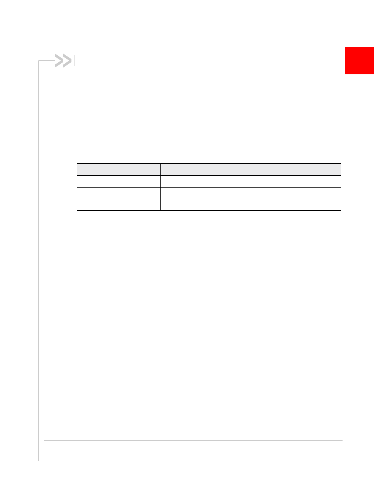
4: Diagnostic Commands
Introduction
This chapter describes commands used to diagnose modem
problems.
Command summary
The table below lists the commands described in this chapter.
Table 4-1: Diagnostic commands
Command Description Page
!BCFWUPDATESTATUS Report status of most recent firmware update attempt 54
!ERR Display diagnostic information 55
!RXDEN Enable/disabl e WCDMA/LTE receive diversity 56
4
Rev. 1 Sep.13 Proprietary and Confidential 53
Page 54

AirPrime MC73xx/8805 AT Command Reference
Command reference
Table 4-2: Diagnostic command details
Command Description
!BCFWUPDATESTATUS
Report status of most recent firmware update attempt
Return the status of the most recent firmware update attempt made since the last cold
restart.
Password required: No
Usage:
• Execution: AT!BCFWUPDATESTATUS
Response:
!BCFWUPDATESTATUS: <result>
or
!BCFWUPDATESTATUS: <result>
Failed IMG TYPE <type>, DATA <data>, PART <part>
OK
Purpose: Return the status of the most recent firmware update attempt. The
second response format appears only if <result> = “FAILED”.
Parameters:
<result> (Status of last firmware update attempt)
• ASCII string:
• “UNKNOWN”—Status of last attempt is unknown.
• “SUCCESS” —Last update was successful.
• “FAILED”—Last update failed.
<type> (Firmware image type that failed to update)
• ASCII string
<data> (Reference data for failed image)
• Location of the reference data as an offset in the CWE image
• Valid range: 0–(2
<part> (Partition associated with the failed image)
32
-1)
• ASCII string
• Applies only to the CUSTOM_IMG case
54 Proprietary and Confidential 4114486
Page 55

Table 4-2: Diagnostic command details (Continued)
Command Description
Diagnostic Commands
!ERR
Display diagnostic information
This command is used to display diagnostic information (logged error conditions) that
Sierra Wireless uses to assist in resolving technical issues.
Password required: Yes
Usage:
• Execution: AT!ERR=0
Response: OK
Purpose: Clear the logged error conditions. Use this command before running
tests to make sure that details displayed using AT!ERR are relevant to
the tests being performed.
• Query: AT!ERR
Response:
Purpose: Return all logged error conditions that are stored in NVRAM.
Parameters:
<count> (Number of occurrences)
• Valid range: 0x00–0xFF
<file> (Log file name)
• Name of log file using ASCII characters
<line> (Line number in log file)
• Valid range: 1–99999
00 [F] <count> <file> <line>
...
nn [F] <count> <file> <line>
OK
Rev. 1 Sep.13 Proprietary and Confidential 55
Page 56

AirPrime MC73xx/8805 AT Command Reference
Table 4-2: Diagnostic command details (Continued)
Command Description
!RXDEN
Enable/disable WCDMA/LTE receive diversity
Enable or disable WCDMA/LTE receive diversity, or establish receive diversity as the
primary path. The new state takes effect the next time the modem is reset.
Note: To change from <state=0> to <state=2> (or from <state=2> to <state=0>, you
must issue AT!RXDEN=1, reset the modem, and then make the final state change.
Password required: Yes—Execution format only
Usage:
• Execution: AT!RXDEN= <state>
Response:
Purpose: Set the current receive diversity state.
• Query: AT!RXDEN?
Response:
Purpose: Return the current receive diversity <state>.
• Query List: AT!RXDEN=?
Purpose: Return a list of availabl e <state> values to use in this command.
Parameters:
<state> (Current/ requested receive diversity state)
• 0 = Rx diversity disabled
• 1 = Rx diversity enabled
• 2 = Rx diversity is primary path
OK
!RXDEN:
<state>
OK
56 Proprietary and Confidential 4114486
Page 57

5: Test Commands
Introduction
To obtain regulatory approval and carrier approvals for your product,
you may be required to perform tests on the radio component of the
embedded modem. This chapter describes AT commands used to
perform those tests.
In most cases the modem must be in a particular mode before you
can issue the AT commands to perform particular tests. Therefore,
the order in which you issue certain commands is important. Three
AT commands are important in setting the mode:
• !DAFTMACT—puts the modem in factory test mode (a non-
signaling mode). You must issue
any other command that starts with “!DA”.
• !DASBAND—selects the frequency band.
You must execute
these commands that test the LTE transceiver:
· !DALGAVGAGC
· !DALGRXAGC
· !DALGTXAGC
You must execute
these commands that test the WCDMA transceiver:
· !DAWGRXAGC
· !DAWGAVGAGC
· !DAWSTXCW
· !DAWSPARANGE
· !DASTXOFF
· !DASTXON
· !DAWSCONFIGRX
You must execute
these commands that test the GSM transceiver:
· !DAGSRXBURST
· !DAGSRXCONT
· !DAGGRSSI
· !DAGGAVGRSSI
· !DAGGRSSIRAW
· !DAGSTXFRAME
• !DASCHAN—selects the channel. This command must be run
after you have selected the band with
select a channel, the modem uses a default.)
5
AT!DAFTMACT before issuing
AT!DASBAND to select an LTE band to run
AT!DASBAND to select a WCDMA band to run
AT!DASBAND to select a GSM band to run
!DASBAND. (If you don’t
Rev. 1 Sep.13 Proprietary and Confidential 57
Page 58

AirPrime MC73xx/8805 AT Command Reference
Command summary
The table below lists the commands described in this chapter.
Table 5-1: Test commands
Command Description Page
!DAFTMACT Put modem into Factory Test Mode 60
!DAFTMDEACT Put modem into online mode from Factory Test Mode 60
!DAGGAVGRSSI Return averaged RSSI value in dBm (GSM only) 61
!DAGGRSSI Return the RSSI value in dBm (GSM only) 61
!DAGGRSSIRAW Return raw RSSI value 62
!DAGINFO Return GSM mode RF information (GSM only) 63
!DAGSLOCK Return synthesizer lock state 64
!DAGSRXBURST Set GSM receiver to burst mode 64
!DAGSRXCONT Set GSM receiver continuously on 65
!DAGSTXBURST Set GSM transmitter to burst mode 65
!DAGSTXFRAME Set GSM Tx frame structure 66
!DALGAVGAGC Return averaged Rx AGC value (LTE only) 67
!DALGRXAGC Return Rx AGC value (LTE only) 68
!DALGTXAGC Return Tx AGC value and transmitter parameters (LTE only) 69
!DALSPARANGE Set LTE PA range (LTE only) 70
!DALSRXBW Set LTE Rx bandwidth (LT E only) 71
!DALSTXBW Set LTE Tx bandwidth (LTE only) 71
!DALSTXINDEX Set LTE Tx gain index (LTE only) 72
!DALSWAVEFORM Set LTE TX waveform (LTE only) 72
!DAOFFLINE Place modem offline 73
!DASBAND Set frequency band 73
!DASCHAN Set modem channel (frequency) 74
!DASLNAGAIN Set LNA gain state 75
!DASPDM Set PDM value 76
!DASTXOFF Turn Tx PA off 76
!DASTXON Turn Tx PA on 77
!DAWGAVGAGC Return averaged Rx AGC value (WCDMA only) 77
!DAWGRXAGC Return Rx AGC value (WCDMA only) 78
58 Proprietary and Confidential 4114486
Page 59

Test Commands
Table 5-1: Test commands (Continued)
Command Description Page
!DAWINFO Return WCDMA mode RF information (WCDMA only) 79
!DAWSCONFIGRX Set WCDMA receiver to factory calibration settings 80
!DAWSPARANGE Set PA range state machine 81
!DAWSSCHAIN Enable secondary receive chain (WCDMA only) 81
!DAWSCHAINTCM Place receive chain in test call mode (WCDMA only) 82
!DAWSTXCW Set waveform used by the transmitter 82
!DAWSTXPWR Set desired Tx power level (WCDMA mode only) 83
!GCDUMP Display crash dump data 83
!IMSTESTMODE Enable/disable IMS test mode 84
Rev. 1 Sep.13 Proprietary and Confidential 59
Page 60

AirPrime MC73xx/8805 AT Command Reference
Command reference
Table 5-2: Test command details
Command Description
!DAFTMACT
!DAFTMDEACT
Put modem into Factory Test Mode
Place the modem in FTM (Factory T est Mode). FTM is a non-signaling mode that allows
the radio component to be manually configured to conduct certain types of tests. AT
commands that start with “!DA” are only available when the modem is in FTM mode.
Note: When this command executes successfully, the modem responds with the value
290300. Any other response indicates an error.
Password required: Yes
Usage:
• Query: AT!DAFTMACT
Response:
290300 (Success. Any other response indicates an error.)
OK
Purpose: Place modem in FTM mode.
Put modem into online mode from Factory Test Mode
This command takes the modem out of FTM and puts the modem back into online
mode. (The command !DAFTMACT puts the modem into FTM.)
Note: When this command executes successfully, the modem responds with the value
290400. Any other response indicates an error.
Password required: Yes
Usage:
• Query: AT!DAFTMDEACT
Response:
Purpose: Place modem in online mode (from FTM mode).
290400 (Success. Any other response indicates an error.)
OK
60 Proprietary and Confidential 4114486
Page 61

Table 5-2: Test command details (Continued)
Command Description
Test Commands
!DAGGAVGRSSI
Note: The modem must be in
FTM mode to use this
command—use
to enter FTM mode.
!DAFTMACT
!DAGGRSSI
Note: The modem must be in
FTM mode to use this
command—use
to enter FTM mode.
!DAFTMACT
Return averaged RSSI value in dBm (GSM only)
Return an averaged RSSI (Received Signal Strength Indicator) value in dBm.
Note:
!DASBAND
!DAGGAVGRSSI
Password required: Yes
Usage:
must be used to set the device to a GSM band before you can use
.
• Execution: AT!DAGGAVGRSSI=<channel>, <LNA Index>
Response:
Purpose: Return the av eraged RSSI for the specified channel and LNA offset
Parameters:
<channel> (Channel number for the band specified using !DASBAND)
OK
index.
• Valid values depend on the selected band
<LNA Index> (LNA offset index)
• 0=R0 (highest gain)
• 1=R1
• 2=R2
• 3=R3 (lowest gain)
Return the RSSI value in dBm (GSM only)
Return the RSSI (Received Signal Strength Indicator) value in dBm using the calibration
offsets (valid in GSM burst mode only—the command !DAGSRXBURST puts the
modem into burst mode).
Note:
!DASBAND
and
!DASCHAN
must be issued before you can use
!DAGGRSSI
.
Password required: Yes
Usage:
• Execution: AT!DAGGRSSI
Response:
Channel:<chan> LNA:<lna> RXPWR:<pwr> dBm
OK
Purpose: Return the av eraged RSSI for the specified channel and LNA offset
index.
Parameters:
<chan> (Channel number for the band specified using !DASBAND)
• Valid values depend on the selected band
<lna> (Current LNA state)
• Valid range: 0–3
<pwr> (RSSI converted to dBm)
• Signed value based on Rx power
Rev. 1 Sep.13 Proprietary and Confidential 61
Page 62

AirPrime MC73xx/8805 AT Command Reference
Table 5-2: Test command details (Continued)
Command Description
!DAGGRSSIRAW
Note: The modem must be in
FTM mode to use this
command—use
to enter FTM mode.
!DAFTMACT
Return raw RSSI value
Return a 32-bit raw RSSI value (valid in GSM mode only). The value is an average over
multiple bursts.
Note:
!DASBAND
!DAGGRSSIRAW
UPassword required: Yes
sage:
• Execution: AT!DAGGRSSIRAW
Response:
Purpose: Return the raw RSSI value.
Parameters
<rssi> (RSSI, averaged over multiple bursts)
• 32-bit value
and
!DASCHAN
.
<rssi>
OK
must be issued before you can use
62 Proprietary and Confidential 4114486
Page 63

Table 5-2: Test command details (Continued)
Command Description
Test Commands
!DAGINFO
Note: The modem must be in
online mode (not FTM mode)
to use this command.
Return GSM mode RF information (GSM only)
Return RF information for GSM mode.
Note:
!DAWINFO
Password required: Yes
Usage:
• Execution: AT!DAGINFO
Response:
Purpose: Return the RF information.
Parameters
<channel> (GSM channel)
• Valid range: 0–65535
<rssi> (Receive power)
• Valid range: 0x00000000–0xFFFFFFFF
<lna> (LNA gain state)
• Valid range: 0–65535
<rxPwr> (Rx power in dBm (0.25 units))
• Valid range: 0–65535
<snr> (Signal-to-noise ratio)
• Valid range: 0–65535
<iOffset> (I offset)
• Valid range: 0–65535
<qOffset> (Q offset)
• Valid range: 0–65535
<freqOffset> (Frequency offset)
• Valid range: 0–65535
<timingOffset> (Timing offset)
• Valid range: 0–65535
provides RF information for WCDMA mode .
Channel: <channel> RSSI:<rssi> LNA:<lna> RXPWR:<rxPwr>
dBm SNR:<snr> DC Offset_I:<iOffset> DC Offset Q:<qOffset>
Freq. Offset:<freqOffset> Timing Offset:<timingOffset>
OK
(If the modem is not in GSM mode, the command returns ‘OK’ with no
information.)
Rev. 1 Sep.13 Proprietary and Confidential 63
Page 64

AirPrime MC73xx/8805 AT Command Reference
Table 5-2: Test command details (Continued)
Command Description
!DAGSLOCK
Note: The modem must be in
FTM mode to use this
command—use
to enter FTM mode.
!DAFTMACT
!DAGSRXBURST
Note: The modem must be in
FTM mode to use this
command—use
to enter FTM mode.
!DAFTMACT
Return synthesizer lock state
Return a value indicating the lock state of the RF synthesizers.
Note:
!DASBAND
Password required: Yes
Usage:
and
!DASCHAN
must be issued before you can use
!DAGSLOCK
• Execution: AT!DAGSLOCK
Response:
<sLockState>
OK
Purpose: Return the synthes izer lock state.
Parameters
<sLockState> (Synthesizer lock state)
• 0=One or more synthesizers are out of lock
• 1=All synthesizers locked
Set GSM receiver to burst mode
Set the receiver to start or stop sending bursts. The receiver must be in burst mode to
read the RSSI. (The command !DAGGRSSI returns the RSSI value.)
Note:
!DASBAND
!DAGSRXBURST
Password required: Yes
Usage:
• Execution: AT!DAGSRXBURST = <function>
Response:
Purpose: Set the receiver to burst mode
Parameters:
<function>
• 0=Get RSSI (Burst mode)
• 2=Stop continuous Rx
and
!DASCHAN
.
<function>
OK
must be issued before you can use
.
64 Proprietary and Confidential 4114486
Page 65

Table 5-2: Test command details (Continued)
Command Description
Test Commands
!DAGSRXCONT
Note: The modem must be in
FTM mode to use this
command—use
to enter FTM mode.
!DAFTMACT
!DAGSTXBURST
Note: The modem must be in
FTM mode to use this
command—use
to enter FTM mode.
!DAFTMACT
Set GSM receiver continuously on
Set the GSM receiver so that it is continuously on and not bursting.
Note:
!DASBAND
!DAGSRXCONT
Password required: Yes
Usage:
and
.
!DASCHAN
must be issued before you can use
• Execution: AT!DAGSRXCONT= <function>
Response:
<function>
OK
Purpose: Set the receiver to continuously on.
Parameters:
<function>
• 3=Receiver continuously on
• 4=Receiver off
Set GSM transmitter to burst mode
Set the transmitter to start or stop sending bursts.
Note:
!DASBAND
!DAGSTXBURST
Password required: Yes
Usage:
• Execution: AT!DAGSTXBURST= <source>, <TSCindex>, <burstdur>
Response:
Purpose: Set the receiver to start/stop sending bursts.
Parameters:
<source>
• 0=Random da ta
• 1=Tone
• 2=Buffer data
<TSCindex> (Training sequence index)
• Valid range: 0–9
<burstdur> Burst duration:
• 1=Continuous
and
!DASCHAN
.
must be issued before you can use
<source> <TSCindex> <burstdur>
OK
Rev. 1 Sep.13 Proprietary and Confidential 65
Page 66

AirPrime MC73xx/8805 AT Command Reference
Table 5-2: Test command details (Continued)
Command Description
!DAGSTXFRAME
Note: The modem must be in
FTM mode to use this
command—use
to enter FTM mode.
!DAFTMACT
Set GSM Tx frame structure
This command configures the Tx slots for GSM operation. It must be issued eight times
to set all eight slots.
Note:
!DASBAND
!DAGSTXFRAME
Password required: Yes
Usage:
• Execution: AT!DAGSTXFRAME= <slotnum>, <onoff>, <pwr>, <mcs>
Response:
Purpose: Set the Tx frame structure.
Parameters:
<slotnum> (Slot number)
• Valid range: 0–7 (eight available Tx slots)
<onoff> (Enable/disable the specified slot)
• 0=Off (disable)
• 1=On (enable)
<pwr> (Slot power level)
• Measured in dB*100
• Maximum values:
• GMSK Mode
850/900 bands: 3200 (32 dBm)
1800/1900 bands: 2900 (29 dBm)
• 8PSK (EDGE) Mode
850/900 bands: 2700 (27 dBm)
1800/1900 bands: 2600 (26 dBm)
<mcs> (Modulation code scheme)
• Valid range: 0–8 (MCS1 to MCS9)
and
!DASCHAN
.
must be issued before you can use
<slotnum> <onoff> <pwr> <mcs>
OK
66 Proprietary and Confidential 4114486
Page 67

Table 5-2: Test command details (Continued)
Command Description
Test Commands
!DALGAVGAGC
Note: The modem must be in
LTE mode to use this
command.
Return averaged Rx AGC value (LTE only)
Return the averaged AGC (Automatic Gain Control) readings for a specific uplink
channel on the main and diversity paths.
Note:
!DASBAND
!DALGAVGAGC
Password required: Yes
Usage:
• Execution: AT!DALGAVGAGC = <channel>, <LNA Index>
Response:
Purpose: Return th e averaged AGC for <channel> on the main and diversity
Parameters:
<channel> (Uplink channel number (UARFCN) for the band specified using !DASBAND)
• Valid values depend on the selected band
<LNA Index> (LNA offset index)
• 0=R0 (Highest gain)
• 1=R1
• 2=R2
• 3=R3 (Lowest gain)
<paths> (Number of receive paths)
• 2
<agc> (AGC value in dBm)
• Valid values: Dynamic Rx range
<chain> (Receive paths)
• 0=Rx Main
• 1=Rx Diversity
and
!DALSRXBW
.
must be issued before you can use
Paths: <paths>
Rx<n>: AGC: <agc> dBm LNA: <lna> Chain: <chain>
Rx<n>: AGC: <agc> dBm LNA: <lna> Chain: <chain>
OK
paths.
Rev. 1 Sep.13 Proprietary and Confidential 67
Page 68

AirPrime MC73xx/8805 AT Command Reference
Table 5-2: Test command details (Continued)
Command Description
!DALGRXAGC
Return Rx AGC value (LTE only)
Return the Rx AGC (Automatic Gain Control) value and LNA gain states for each RF
path.
The AGC value can be converted to RSSI (Received Signal Strength Indicator) in dBm:
if (<AGC_value> < 511)
<RX_dBm> = -106 + ( ( <AGC_value> + 512 ) / 12 )
else
<RX_dBm> = -106 + ( ( (<AGC_value>-1024) + 512 ) / 12 )
Note:
!DASBAND
Password required: Yes
Usage:
• Execution: AT!DALGRXAGC or AT!DALGRXAGC?
Response:
Purpose: Return the <AGC value> for either the main or diversity path. If no
Parameters:
<path> (For modules supporting diversity)
• 0=Main path
• 1=Diversity path
<AGC value> (Rx AGC value for specified path)
• Valid range: -512 to +511
and
!DASCHAN
must be issued before you can use
<AGC value>
OK
<path> is specified, the main path is assumed.
!DALGRXAGC
.
68 Proprietary and Confidential 4114486
Page 69

Table 5-2: Test command details (Continued)
Command Description
Test Commands
!DALGTXAGC
Return Tx AGC value and transmitter parameters (LTE only)
Return the Tx AGC (Automatic Gain Control) value and other transmitter parameters.
Note: This command works only in an active call (for example, when connected to a
call box or live network).
Note:
!DASBAND
Password required: Yes
Usage:
• Execution: AT!DALGTXAGC or AT!DALGTXAGC?
Response:
Purpose: Return transmitter parameters and the transmit <AGC value>.
Parameters:
<paths> (Number of transmit paths)
• 1 (Tx)
<agc> (Tx AGC value in dBm)
• Valid range: -70 to +23
<rbi>
• Start resource block index
<rbn> (Number of resource blocks)
• Valid range: 0–50
<pa> (PA gain state)
• Valid range: 0–3
<txgi>
• Tx gain index
<mtpl> (Max Tx power limit)
• Max value: +23
<iq>
• Digital IQ gain scaling
<mpr> (Maximum power reduction)
• See 3GPP 36.101 for details
<ampr> (Additional Max power reduction)
• See 3GPP 36.101 for details
<ns> (Network Signaled (NS) value)
• See 3GPP 36.101 for details
and
!DASCHAN
must be issued before you can use
!DALGTXAGC
Paths: <paths>
Tx<n>:AGC: <agc> dBm RBi: <rbi> RB: <rbn> PA: <pa>
TxGainIdx: <txgi> MTPL: <mtpl> dBm IQgain: <iq>
MPR: <mpr> AMPR: <ampr> NS: <ns>
SARmpr: <sarmpr> PDet Mode: <mode>
PDetAGC: <pagc> PDet: <pdbm> Traw: <traw>
Tscaled: <tscaled> Tidx: <tidx> Trem: <trem>
OK
.
(Continued on next page)
Rev. 1 Sep.13 Proprietary and Confidential 69
Page 70

AirPrime MC73xx/8805 AT Command Reference
Table 5-2: Test command details (Continued)
Command Description
!DALGTXAGC
(continued)
!DALSPARANGE
Return Tx AGC value and transmitter parameters (LTE only)
(continued)
<mode> (HDET (power detector) mode)
• Valid values:
• L (Lower power)
• H (Higher power)
<padc>
• HDET ADC
<pdbm>
• HDET dBm
<traw> (Raw thermistor ADC value)
• Valid range: 0–4095
<tscaled> (Scaled thermistor value)
• Valid range: 0–255
• Value is scaled from <traw> based on calibrated min/max <traw> values for the
supported temperature range.
<tidx> (Temperature compensation bin)
• Valid range: 0–7
<trem>
• Temperature compensation remainder bin
Set LTE PA range (LTE only)
Set the LTE PA (Power Amplifier) range.
Requirements:
• Device must be in FTM mode
• !DASBAND, !DASCHAN, and !DALSTXBW must be issued before you can use
this command.
Password required: Yes
Usage:
• Execution: AT!DALSPARANGE=<pa_range>
Response:
Purpose: Set the LTE PA range.
Parameters:
<pa_range> (PA range)
• 0
• 1
• 2
• 3
OK
70 Proprietary and Confidential 4114486
Page 71

Table 5-2: Test command details (Continued)
Command Description
Test Commands
!DALSRXBW
!DALSTXBW
Set LTE Rx bandwidth (LTE only)
Set the LTE Rx bandwidth.
Requirements:
• !DASBAND must be issued before you can use this command.
• This command must be issued before you can use !DALGAVGAGC.
Password required: Yes
Usage:
• Execution: AT!DALSRXBW=<bw>
Response:
Purpose: Set the LTE Rx bandwidth.
Parameters:
<bw> (LTE bandwidth)
OK
• 0=1.4MHz
• 1=3MHz
• 2=5MHz
• 3=10 MHz
• 4=15 MHz
• 5=20 MHz
Set LTE Tx bandwidth (LTE only)
Set the LTE Tx bandwidth.
Requirements:
• !DASBAND must be issued before you can use this command.
Password required: Yes
Usage:
• Execution: AT!DALSTXBW=<bw>
Response:
Purpose: Set the LTE Tx bandwidth.
Parameters:
<bw> (LTE bandwidth)
• 0=1.4MHz
• 1=3MHz
• 2=5MHz
• 3=10 MHz
• 4=15 MHz
• 5=20 MHz
OK
Rev. 1 Sep.13 Proprietary and Confidential 71
Page 72

AirPrime MC73xx/8805 AT Command Reference
Table 5-2: Test command details (Continued)
Command Description
!DALSTXINDEX
!DALSWAVEFORM
Set LTE Tx gain index (LTE only)
Set the LTE Tx gain index.
Requirements:
• Device must be in FTM mode
• !DASBAND, !DASCHAN, and !DALSTXBW must be issued before you can use
this command.
Password required: Yes
Usage:
• Execution: AT!DALSTXINDEX=<tx_index>
Response:
Purpose: Set the LTE Tx gain index.
Parameters:
<tx_index> (LTE Tx gain index)
OK
• Valid range: 0–127
Set LTE TX waveform (LTE only)
Set the LT E Tx waveform characteristics.
Requirements:
• Device must be in FTM mode
• !DASBAND, !DASCHAN, and !DALSTXBW must be issued before you can use
this command.
Password required: Yes
Usage:
• Execution: AT!DALSWAVEFORM=<waveform>[,<PUSCH_RBs>,
<PUCCH_RBs>,<PUSCH_start_RB_index>]
Response: OK
Purpose: Set the LTE Tx waveform characteristics.
Parameters:
<waveform> (Tx waveform)
• 0=1 MHz offset CW
• 1=LTE PUSCH (Physical Uplink Shared Channel)
• 2=LTE PUCCH (Physical Uplink Control Channel)
• 3=LTE PRACH (Physical Random Access Channel)
• 4=LTE SRS
• 5=UpPTS (Uplink Pilot Time Slot
<PUSCH_RBs> (Number of PUSCH resource blocks
• Valid rnage: 0–100
<PUCCH_RBs> (Number of PUCCH resource blocks)
• Valid range: 0–12
<PUSCH_start_RB_index> (PUSCH starting resource block index
• Valid range: 0–255
72 Proprietary and Confidential 4114486
Page 73

Table 5-2: Test command details (Continued)
Command Description
Test Commands
!DAOFFLINE
!DASBAND
Note: The modem must be in
FTM mode to use this
command—use
to enter FTM mode.
!DAFTMACT
Place modem offline
Put the modem offline.
Password required: Yes
Usage:
• Execution: AT!DAOFFLINE
Response:
Purpose: Put the modem offline.
Parameters:
None
OK
Set frequency band
Set the modem to use a particular frequency band. You must use this command to
select an appropriate band before running LTE, WCDMA, or GSM commands. See
page 57.
Password required: Yes
Usage:
• Execution: AT!DASBAND = <rfband>
Response:
Purpose: Set fre quency band.
Parameters:
<rfband> (Unique value corresponding to an RF band and technology.)
• This is a unique value that maps to an RF band and technology. It is not an
actual 3GPP band number. For example, ‘18’ is GSM 85 0, which corresponds to
3GPP band 5 (on a GSM network).
• Band support is product specific—see the device’s Product Specification or
Product Technical Specification document for details.
• Examples (for a full listing, see Table 13-1 on page 143):
• GSM
• WCDMA
• LTE
<rfband>
OK
• 10=GSM 900
• 11=GSM 1800
• 12=GSM 1900
• 18=GSM 850
• 9=WCDMA 2100
• 16=WCDMA 1900B
• 22=WCDMA 850
• 29=WCDMA 900 (BC8)
• 34=LTE B1
• 35=LTE B7
• 36=LTE B13
• 37=LTE B17
• 42=LTE B4
• 44=LTE B3
• 47=LTE B8
• 56=LTE B20
Rev. 1 Sep.13 Proprietary and Confidential 73
Page 74

AirPrime MC73xx/8805 AT Command Reference
Table 5-2: Test command details (Continued)
Command Description
!DASCHAN
Note: The modem must be in
FTM mode to use this
command—use
to enter FTM mode.
!DAFTMACT
Set modem channel (frequency)
Set the modem to operate on a particular frequency channel. Before using this
command, use the command !DASBAND (described on page 73) to set the band.
Once a channel is set, the modem continues to use that channel until the modem is
reset or powered off and on.
Note:
!DASBAND
Password required: Yes
Usage:
• Execution: AT!DASCHAN=<rfchannel>
Response:
Purpose: Set mode m channel (frequency).
Parameters:
<rfchannel> (Uplink channel number (ARFCN)—depends on frequency band being
used)
• 128–251: GSM 850 MHz
• 1–24: GSM 900 MHz
• 975–1023: GSM 900 MHz
• 512–885: GSM 1800 MHz
• 512–810: GSM 1900 MHz
• 9612–9888: WCDMA 2100
• 9262–9538: WCDMA 1900
• 4132–4233: WCDMA 850
• 2712–2863: WCDMA 900
• 18000–18599: LTE B1
• 19200–19949: LTE B3
• 19950–20399 LTE B4
• 20750–21449: LTE B7
• 21450–21799: LTE B8
• 23180–23279: LTE B13
• 23730–23849: LTE B17
• 24150–24449: LTE B20
must be issued before you can use
<rfchannel>
OK
!DASCHAN
.
74 Proprietary and Confidential 4114486
Page 75

Table 5-2: Test command details (Continued)
Command Description
Test Commands
!DASLNAGAIN
Set LNA gain state
Set the LNA (Low Noise Amplifier) range for the main or diversity path (if applicable), in
either WCDMA or GSM mode.
Note:
!DASBAND
Password required: Yes
Usage:
• Execution: AT!LNAGAIN =<gain index>[, <path>]
Response:
Purpose: Set the LNA gain state for either the main or diversity paths.
Parameters:
<gain index>
• 0=R0 (highest gain)
Approximate switch from low to high gain: WCDMA (< -72 dBm);
GSM (< -73 dBm)
• 1=R1
Approximate switch from low to high gain: WCDMA (< -72 up to -46 dBm);
GSM (< -73 up to -58 dBm)
• 2=R2
Approximate switch from low to high gain: WCDMA (< -46 up to -36 dBm);
GSM (< -58 up to -41 dBm)
• 3=R3 (lowest gain)
Approximate switch from low to high gain: WCDMA (> -36 dBm);
GSM (< -41 dBm)
and
!DASCHAN
<gain index>
OK
must be issued before you can use
!DASLNAGAIN
.
Note: The LNA gain state is set based on the expected receive power level. The gain
state values listed above are provided as a guideline. The values are approximations
and subject to change over time. The values are different than those from high to low
gain.
<path> (For modules supporting diversity)
• 0=Main path
• 1=Secondary (diversity) path
Rev. 1 Sep.13 Proprietary and Confidential 75
Page 76

AirPrime MC73xx/8805 AT Command Reference
Table 5-2: Test command details (Continued)
Command Description
!DASPDM
Note: The modem must be in
FTM mode to use this
command—use
to enter FTM mode.
!DAFTMACT
Set PDM value
Adjust the PDM (Pulse Duration Modulation), allowing you to apply frequency offset to
the LO (Local Oscillator) or Tx AGC.
When you adjust the Tx AGC (<PDM ID> = 2), the modem does not use a calibrated
result but uses the raw AGC value. The resulting change in Tx power will vary from
modem to modem, so it is usually necessary to tune this value by executing the
command repeatedly with different settings for the <PDMvalue> until you obtain the
desired Tx power.
When adjusting the tracking LO, yo u also need to execute the command repeatedly with
different settings for the <PDMvalue> until you obtain the desired frequency offset.
Note:
!DASBAND
Password required: Yes
Usage:
• Execution: AT!DASPDM= <PDM ID>, <PDMvalue>
Response:
Purpose: Set the tra c king LO and Tx AGC PDM.
Parameters:
<PDM ID> (LO (Local Oscillator) or Tx AGC (Automatic Gain Control) to adjust)
• 0=Tracking LO adjust (GSM only)
• 2=Tx AGC adjust (WCDMA only)
• 4=Tracking LO adjust (WCDMA only)
<PDMvalue> (Frequency offset value)
• If <PDM ID>=0: 0–51 1
• If <PDM ID>=2: 0–51 1
• If <PDM ID>=5: 0–65536
and
!DASCHAN
must be issued before you can use
<PDM ID> <PDMvalue>
OK
!DASPDM
.
!DASTXOFF
Note: The modem must be in
FTM mode to use this
command—use
to enter FTM mode.
!DAFTMACT
Turn Tx PA off
Turn the transceiver PA off, after it has been turned on with !DASTXON.
Note:
!DASBAND
Password required: Yes
Usage:
and
!DASCHAN
must be issued before you can use
!DASTXOFF
.
• Execution: AT!DASTXOFF
Response:
Purpose: Turn the Tx PA off.
Parameters:
None
OK
76 Proprietary and Confidential 4114486
Page 77

Table 5-2: Test command details (Continued)
Command Description
Test Commands
!DASTXON
Note: The modem must be in
FTM mode to use this
command—use
to enter FTM mode.
!DAFTMACT
!DAWGAVGAGC
Turn Tx PA on
Turn on the transceiver PA (either the WCDMA PA or the GSM PA, depending on the
mode set with !DASBAND). The PA then remains on until you turn it off using the
!DASTXOFF command, or until you reset or power the modem down and up.
Note:
!DASBAND
Password required: Yes
Usage:
and
!DASCHAN
must be issued before you can use
!DASTXON
• Execution: AT!DASTXON
Response:
Purpose: Turn the Tx PA on.
Parameters:
None
OK
Return averaged Rx AGC value (WCDMA only)
Return the averaged AGC (Automatic Gain Control) reading for a specific band for either
the main path or diversity path (if applicable).
Note:
!DASBAND
Password required: Yes
Usage:
• Execution: AT!DAWGAVGAGC=<channel>, <LNA Index>[, <path>]
Response: <agc>
Purpose: Return the averaged AGC for <channel> on the main path or diversity
Parameters:
<channel> (Uplink channel number (UARFCN) for the band specified using !DASBAND)
• Valid values depend on the selected band
<LNA Index> (LNA offset index)
• 0=R0 (Highest gain)
• 1=R1
• 2=R2
• 3=R3 (Lowest gain)
<path> (For modules supporting diversity)
• 0=Main path
• 1=Diversity path
<agc> (Averaged Rx AGC in dBm)
• Example: -78.9
must be issued before you can use
OK
path.
!DAWGAVGAGC
.
.
Rev. 1 Sep.13 Proprietary and Confidential 77
Page 78

AirPrime MC73xx/8805 AT Command Reference
Table 5-2: Test command details (Continued)
Command Description
!DAWGRXAGC
Return Rx AGC value (WCDMA only)
Return the Rx AGC (Automatic Gain Control) value of the main path or diversity path (if
applicable).
This value can be converted to RSSI (Received Signal Strength Indicator) in dBm:
if (<AGC_value> < 511)
<RX_dBm> = -106 + ( ( <AGC_value> + 512 ) / 12 )
else
<RX_dBm> = -106 + ( ( (<AGC_value>-1024) + 512 ) / 12 )
Note:
!DASBAND
Password required: Yes
Usage:
• Execution: AT!DAWGRXAGC?[<path>]
Response:
Purpose: Return the <AGC value> for either the main or diversity paths. If no
Parameters:
<path> (For modules supporting diversity)
• 0=Main path
• 1=Diversity path
<AGC value> (Rx AGC value for specified path)
• Valid range: -512 to +511
and
!DASCHAN
must be issued before you can use
<AGC value>
OK
<path> is specified, the main path is assumed.
!DAWGRXAGC
.
78 Proprietary and Confidential 4114486
Page 79

Table 5-2: Test command details (Continued)
Command Description
Test Commands
!DAWINFO
Note: The modem must be in
online mode (not FTM mode)
to use this command.
Return WCDMA mode RF information (WCDMA only)
Return RF information for WCDMA mode when the modem is in CELL_DCH
(Designated Channel) state.
Note:
!DAGINFO
Password required: Yes
Usage:
• Execution: AT!DAWINFO
Response:
Purpose: Return the RF information.
Parameters:
<rxAGC> (Rx AGC value)
• Valid range: 0–65535
<txAGC> (Tx AGC value)
• Valid range: 0–65535
<txAdj> (Tx AGC value after linearization (adjustment))
• Valid range: 0–65535
<txLim> (Tx AGC limit)
• Valid range: 0–65535
<lnaRange> (State of the LNA)
• Valid range: 0–65535
<paOn> (State of PA_ON0)
• Valid range: 0–65535
<txOn> (State of TX_ON)
• Valid range: 0–65535
<paRange> (State of PA_R1: PA_R0)
• Valid range: 0–65535
<RXDrxAGC> (RxD Rx AGC value)
• Valid range: 0–65535
<RXDlnaRange> (State of the RxD LNA)
• Valid range: 0–65535
<hdet> (Raw HDET (High Power Detector) data)
• Valid range: 0–255
provides RF information for GSM mode.
RXAGC:<rxAGC> TXAGC:<txAGC> TXADJ:<txAdj>
TXLIM:<txLim> LNA:<lnaRange> PA ON:<paOn>
TX ON:<txOn> PA Range:<paRange>
RxD RXAGC:<RXDrxAGC> RxD LNA:<RXDlnaRange>
HDET:<hdet>
OK
Rev. 1 Sep.13 Proprietary and Confidential 79
Page 80

AirPrime MC73xx/8805 AT Command Reference
Table 5-2: Test command details (Continued)
Command Description
!DAWSCONFIGRX
Note: The modem must be in
FTM mode to use this
command—use
to enter FTM mode.
!DAFTMACT
Set WCDMA receiver to factory calibration settings
Configure the WCDMA receiver according to factory calibration settings stored in the
modem’s NV (Non-Volatile memory). This allows for accurate measurement of Rx AGC
levels.
The command performs these steps:
1. Sets the channel.
2. Selects and sets LNA range (or LNA gain).
3. Sets the VGA gain offset based on the channel.
4. Sets the LNA range offset.
Note:
!DASBAND
!DAWSCONFIGRX
Password required: Yes
Usage:
• Execution: AT!DAWSCONFIGRX = <channel>,<Rx_Level_dBm>
Response:
Purpose: Configure the receiver.
Parameters (Input):
<channel> (Uplink channel number (ARFCN))
• Value based on the selected band
<Rx_Level_dBm> (Approximate signal level (in dBm) being applied to the modem
receiver)
• Valid range: -113 to 20
Parameters (Output):
<LNA Index> (LNA offset index)
• 0=R0 (highest gain)
• 1=R1
• 2=R2
• 3=R3 (lowest gain)
<LNA Value>
• Internal use only
and
!DASCHAN
.
must be issued before you can use
<LNA Index>, <LNA Value>
OK
80 Proprietary and Confidential 4114486
Page 81

Table 5-2: Test command details (Continued)
Command Description
Test Commands
!DAWSPARANGE
Note: The modem must be in
FTM mode to use this
command—use
to enter FTM mode.
!DAFTMACT
!DAWSSCHAIN
Set PA range state machine
Set the PA range state machine in WCDMA operation.
Note:
!DASBAND
!DAWSPARANGE
Password required: Yes
Usage:
and
!DASCHAN
.
must be issued before you can use
• Execution: AT!DAWSPARANGE = <PA range>
Response:
<PA range>
OK
Purpose: Set the PA range state machine.
Parameters:
<PA range>
• 0=Low gain state of the PA — Limited to about 16 dBm output power (R0=0,
R1=0)
• 3=High gain state of the PA — Up to the maximum output power of the modem
(R0=1, R1=1)
Enable secondary receive chain (WCDMA only)
Enable or disable the secondary receive chain.
Note:
!DASBAND
and
!DASCHAN
must be issued before you can use
!DAWSSCHAIN
.
Password required: Yes
Usage:
• Execution: AT!DAWSSCHAIN=<state>
Response:
Purpose: Enable or disable the secondary receive chain.
Parameters:
<state> (Requested state for secondary receive chain)
OK
• 0=Off (Disable)
• 1=On (Enable)
Rev. 1 Sep.13 Proprietary and Confidential 81
Page 82

AirPrime MC73xx/8805 AT Command Reference
Table 5-2: Test command details (Continued)
Command Description
!DAWSCHAINTCM
!DAWSTXCW
Note: The modem must be in
FTM mode to use this
command—use
to enter FTM mode.
!DAFTMACT
Place receive chain in test call mode (WCDMA only)
Place one or both of the primary and secondary receive chains in test call mode.
Note:
!DASBAND
!DAWSCHAINTCM
Password required: Yes
Usage:
and
!DASCHAN
.
must be issued before you can use
• Execution: AT!DAWSCHAINTCM= <chain>
Response:
Purpose: Place reque sted receive chain(s) in test call mode.
Parameters:
<chain> (Receive chain to place in test call mode)
OK
• 0=Main
• 1=Secondary
• 2=Both
Set waveform used by the transmitter
Set the waveform used by the transmitter—the modem can transmit either in carrier
wave or WCDMA modulated.
Note:
!DASBAND
Password required: Yes
Usage:
• Execution: AT!DAWSTXCW= <waveform>
Response:
Purpose: Set the transmitter waveform.
Parameters:
<waveform> (Waveform used by the transmitter)
• 0=WCDMA
• 1=Carrier wave (no modulating signal applied)
and
!DASCHAN
OK
must be issued before you can use
!DAWSTXCW
.
82 Proprietary and Confidential 4114486
Page 83

Table 5-2: Test command details (Continued)
Command Description
Test Commands
!DAWSTXPWR
Note: The modem must be in
FTM mode to use this
command—use
to enter FTM mode.
!DAFTMACT
Set desired Tx power level (WCDMA mode only)
Set the desired Tx power level in dBm. When this occurs, the PA range and PDM are
automatically updated as well. (When this command is used, you do not need to use
!DAWSPARANGE and !DASPDM.)
Note:
!DASBAND
Password required: Yes
Usage:
• Execution: AT!DAWSTXPWR = <dBm>[,<use_temp_comp>]
Response:
Purpose: Set the Tx pow er level to the requested <dBm> level, and automati-
Parameters:
<dBm> (Desired Tx power in dBm)
• Valid range: -57 to 28
<use_temp_comp> (Apply temperature compensation to set desired Tx pow er.)
• Frequency compensation is always applied.
• 0=No (default)
• 1=Yes
<pa_range> (PA range set as a result of the command)
• Valid range: 0–3
<pdm> (PDM set as a result of the command)
• Valid range: 0–255
and
!DASCHAN
must be issued before you can use
<pa_range>, <pdm>
OK
cally set the PA range and PDM.
!DAWSTXPWR
.
!GCDUMP
Display crash dump data
Display crash dump data.
Password required: No
Usage:
• Execution: AT!GCDUMP
Response:
(crash dump data)
OK
or No crash data available
OK
Purpose: Display crash dump data.
Rev. 1 Sep.13 Proprietary and Confidential 83
Page 84

AirPrime MC73xx/8805 AT Command Reference
Table 5-2: Test command details (Continued)
Command Description
!IMSTESTMODE
Enable/disable IMS test mode
Enable/disable IMS (IP Multimedia Subsystem) test mode.
If IMS test mode is enabled:
• IMS registration attempts will not occur
• SMS is not supported
Password required: Yes
Usage:
• Execution: AT!IMSTESTMODE=<mode>
Response:
Purpose: Enable/disable IMS test mode.
• Query: AT!IMSTESTMODE?
Response:
Purpose: Return the current state of IMS Test Mode.
Parameters:
<mode> (IMS Test Mode state)
• 0=Disable
• 1=Enable
OK
IMS Test Mode Enabled
or IMS Test Mode Disabled
84 Proprietary and Confidential 4114486
Page 85

6: Memory Management Commands
Introduction
The modem uses non-volatile memory to store:
• Factory calibration data
• Settings made in a host application such as Watcher.
The commands in this chapter allow you to back up and restore the
data in non-volatile memory.
Command summary
The table below lists the commands described in this chapter:
Table 6-1: Memory management commands
Command Description Page
!NVDEF Reset non-volatile memory 86
!NVRESTORE Restore backup data 86
6
Rev. 1 Sep.13 Proprietary and Confidential 85
Page 86

AirPrime MC73xx/8805 AT Command Reference
Command reference
Table 6-2: Memory management command details
Command Description
!NVDEF
Reset non-volatile memory
Warning: This command erases all calibration data, customizations, etc. First use
!NVBACKUP
(p.86) to restore the settings.
Note: Profiles (PDP contexts) are not restored using AT commands. The host application is
responsible for implementing this task.
Reset non-volatile memory to default values and then restore the modem’s FSN. All
calibration data, customizations, etc., are removed.
Note: This command may take 20–30 seconds to complete.
Password required: Yes
Usage:
• Execution: AT!NVDEF
Response:
Purpose: Clear and reset NV items.
Parameters:
<defaulted> (Number of NV items defaulted)
• Valid range: 0–65535 (This number varies depending on firmware version.)
to save these settings, and then, after using this command, use
!NVRESTORE
!NVDEF: Wiping NV, restoring defaults for S1614350476E10F (FSN
shown is an example)
NV Items Defaulted: <defaulted>
OK
!NVRESTORE
Restore backup data
Restore items to non-volatile memory that were backed up with the command
AT!NVBACKUP, and return the number of NV items restored.
Password required: Yes
Usage:
• Execution: AT!NVRESTORE = <category>
Response:
!NVRESTORE:
NV Items Restored: <restored>
OK
Purpose: Clear and reset NV items.
Parameters:
<category> (Item type to be restored)
• 0=Factory items (RF calibration data)
• 1=OEM items (Factory configuration, unless user has performed an
AT!NVBACKUP=1)
• 2=User items (Configuration as of most recent firmwa re downl oad, including all user
customizations)
• 3=Cache (Boot and frequently updated NV items)
<restored> (Number of NV items restored)
• Valid range: 0–255
86 Proprietary and Confidential 4114486
Page 87

7: GPS Commands
Introduction
This chapter describes commands used to access GPS functionality
in supporting modules.
When using these commands, the following considerations apply:
• GPS is typically enabled by default; however, it may be disabled
by default for some SKUs. If so, enable GPS using
AT!CUSTOM=”GPSENABLE”
• If supported by the modem, gpsOneXTRA is enabled (over the
NDIS interface) by default when GPS is enabled, and it
generates data traffic.
Command summary
The table below lists the commands described in this chapter.
Table 7-1: GPS commands
Command Description Page
7
!GPSAUTOSTART Configure GPS auto-start features 89
!GPSCLRASSIST Clear specific GPS assistance data 90
!GPSEND End an active session 91
!GPSFIX Initiate GPS position fix 92
!GPSKEEPWARM Configure Keep Warm functionality 93
!GPSLBSAPN Set GPS LBS APNs 94
!GPSLOC Return last known location of the modem 96
!GPSMOMETHOD Set/report GPS MO method 97
!GPSMTLRSETTINGS Set/report MT locatio n request settings 98
!GPSNIQOSTIME Set/report GPS QoS timeout period for network-initialized
fixes
!GPSNMEA Enable/disable NMEA streaming 99
!GPSNMEACONFIG Enable and set NMEA data output rate 99
!GPSNMEASENTENCE Set/report NMEA sentence type 100
!GPSPORTID Set/report port ID to use over TCP/IP 101
!GPSPOSMODE Configure support for GPS positioning modes 102
98
!GPSSATINFO Request satellite information 103
Rev. 1 Sep.13 Proprietary and Confidential 87
Page 88

AirPrime MC73xx/8805 AT Command Reference
Table 7-1: GPS commands (Continued)
Command Description Page
!GPSSTATUS Request current status of a position fix session 104
!GPSSUPLURL Set/report SUPL server URL 105
!GPSSUPLVER Set/report SUPL server version 105
!GPSTRACK Initiate local tracking (multiple fix) session 106
!GPSTRANSSEC Control GPS transport security 107
!GPSXTRAAPN Set GPS XTRA APNs 108
!GPSXTRADATAENABLE Set/report GPS XTRA settings 109
!GPSXTRADATAURL Set/report GPS XTRA data server URLs 110
!GPSXTRAINITDNLD Initiate gpsOneXTRA data download and inject operation 110
!GPSXTRASTATUS Return current status of gpsOneXTRA 111
!GPSXTRATIME Inject GPS or UTC time into gpsOneXTRA system 112
!GPSXTRATIMEENABLE Set/report GPS XTRA time settings 113
!GPSXTRATIMEURL Set/report GPS XTRA SNTP server URLs 114
88 Proprietary and Confidential 4114486
Page 89

Command reference
Table 7-2: GPS command details
Command Description
GPS Commands
!GPSAUTOSTART
Min f/w rev: 4.0
•
Configure GPS auto-start features
Configure the GPS auto-start features. Any changes take effect the next time the
modem is reset.
Note: If auto-start is enabled, another GPS session cannot be started.
Password required: No
Usage:
• Execution: AT!GPSAUTOSTART=<enable>[, <fixtype>, <maxtime>,
<maxdist>, <fixrate>]
Response: OK
or ERROR
Purpose: Assign start values for vario us GPS settings
• Query: AT!GPSAUTOSTART?
Response: !
Purpose: Display the current values for auto-start features
• Query List: AT!GPSAUTOSTART=?
Purpose: Return the expe cted command format.
Parameters:
<enable> (Enable/disable the feature)
• 0=Disabled
• 1=Enabled (GPS tracking session starts automatically when modem is reset)
<fixtype> (Type of fix to establish)
• 1=Standalone (not supported by a mobile station)
• 2=MS-based only
• 3=MS-assisted only
<maxtime> (Maximum time to wait for a position fix)
• Valid range: 0–255—Number of seconds to wait
<maxdist> (Requested accuracy of fix)
• Entered in decimal format
• Valid range:
• 0–4294967279 meters
• 4294967280=No preference
<fixrate> (Time to wait between fixes)
• Valid range: 1–65535 seconds
GPSAUTOSTART
enable: <enable>
fixtype: <fixtype>
maxtime: <maxtime> seconds
maxdist: <maxdist> meters
fixrate: <fixrate> seconds
OK
Rev. 1 Sep.13 Proprietary and Confidential 89
Page 90

AirPrime MC73xx/8805 AT Command Reference
Table 7-2: GPS command details (Continued)
Command Description
!GPSCLRASSIST
Min f/w rev: 4.0
•
Clear specific GPS assistance data
Clear one or more types of assistance data from the modem. This forces a cold start
for GPS acquisition the next time a session starts.
The command is only available when there is no active GPS session—the GPS
receiver is off and no position fix is being calculated.
This command is equivalent to !GPSCOLDSTART when all four parameters are set
to ‘1’.
Password required: Yes
Usage:
• Execution: AT!GPSCLRASSIST = <eph>, <alm>, <pos>, <time>, <iono>
Response:
Purpose: Clear each assistance data type that is flagged as ‘1’.
• Query List: AT!GPSCLRASSIST=?
Purpose: Return the expected command format and supported values.
Parameters:
<eph> (Ephemeris assistance data)
• 0=Ignore (Do not clear the ep hemeris assistance data)
• 1=Clear this assistance data type—Clears GPS, GLONASS, and SBAS
ephemeris assistance data.
<alm> (Almanac assistance data)
• 0=Ignore (Do not clear the almanac assistance data)
• 1=Clear this assistance data type—Clears GPS, GLONASS, and SBAS
almanac assistance data.
<pos> (Position assistance data)
• 0=Ignore (Do not clear the position assistance data)
• 1=Clear this assistance data type
<time> (Time reference)
• 0=Ignore (Do not clear the time reference)
• 1=Clear the time reference
<iono> (Ionosphere assistance data)
• 0=Ignore (Do not clear the ion osphere assistance data)
• 1=Clear this assistance data type
OK
or Command ignored
OK
90 Proprietary and Confidential 4114486
Page 91

Table 7-2: GPS command details (Continued)
Command Description
GPS Commands
!GPSEND
•
Min f/w rev: 4.0
End an active session
End an active position fix session.
Password required: No
Usage:
• Execution: AT!GPSEND=<sessType>
Response:
Purpose: End the current session.
Parameters:
<sessType> (Type of session to end)
• 0=Position fix session
<value> (Error code returned when command fails for any reason)
• See Table 7-3 on page 114 for a list of possible error codes.
ERRCODE = <value>
OK
or OK
Rev. 1 Sep.13 Proprietary and Confidential 91
Page 92

AirPrime MC73xx/8805 AT Command Reference
Table 7-2: GPS command details (Continued)
Command Description
!GPSFIX
Min f/w rev: 4.0
•
Initiate GPS position fix
Initiate a GPS position fix.
Password required: No
Usage:
• Execution: AT!GPSFIX=<fixType>, <maxTime>, <maxDist>
Response:
Purpose: Initiate a time-limited position fix with a specified accuracy.
• Query List: AT!GPSFIX=?
Purpose: Return supported <fixType>, <maxTime>, and <maxDist> values.
Parameters:
<fixType> (Type of fix to establish)
• 1=Standalone (not supported by a mobile station)
• 2=MS-based only
• 3=MS-assisted only
<maxTime> (Maximum time to wait for a position fix)
• Valid range: 0–255 seconds
<maxDist> (Requested accuracy of fix)
• Entered in decimal format
• Valid range:
• 0–4294967279 meters
• 4294967280=No preference
<value> (Error code returned when command fails for any reason)
• See Table 7-3 on page 114 for a list of possible error codes.
Example:
AT !GPSFIX=1, 15, 10 requests a standalone position fix to 10 meters accuracy. The
request will fail (timeout) if the modem cannot determine a position fix within
15 seconds.
Related commands:
• !GPSSTATUS (page 104)—Use this command while the tracking session is in
progress.
• !GPSLOC (page 96)—Use this command after the session completes to obtain
the result.
Fix initiated
OK
or ERROR CODE = <value>
OK
92 Proprietary and Confidential 4114486
Page 93

Table 7-2: GPS command details (Continued)
Command Description
GPS Commands
!GPSKEEPWARM
•
Min f/w rev: 4.0
Configure Keep Warm functionality
Set, clear, or report the modem’s ‘keep warm’ functionality. This functionality
downloads GPS assistance data from the GPS server.
Password required: Yes
Usage:
• Execution: AT!GPSKEEPWARM= <enableFlag>
Response:
Purpose: Enable/disable the keep warm functionality.
• Query: AT!GPSKEEPWARM?
Response:
Purpose: Display the current status (<enableFlag>) of the keep warm
• Query List: AT!GPSKEEPWARM=?
Purpose: Display valid <enableFlag> options.
Parameters:
<enableFlag> (Enable/disable keep warm functionality)
• 0=Disable
• 1=Enable
<warmStatus> (GPS is in Warm state)
• 0=No
• 1=Yes
Example:
AT!GPSKEEPWARM? returns:
KeepWarm Enabled: 1
Warm Status: 1
In this example, KeepWarm is enabled, and GPS is in Warm state.
OK
KeepWarm Enabled: <enableFlag>
Warm Status: <warmStatus>
functionality and indicate if GPS is in ’warm’ state (<warmStatus>).
Rev. 1 Sep.13 Proprietary and Confidential 93
Page 94

AirPrime MC73xx/8805 AT Command Reference
Table 7-2: GPS command details (Continued)
Command Description
!GPSLBSAPN
Set GPS LBS APNs
Set the GPS LBS APNs to be used for various RATs (Radio Access Technologies).
Password required: Yes
Usage:
• Execution (Add):
AT!GPSLBSAPN=<operation>,<ratmask>,<IPtype>,<APN>
Execution (Delete one):
AT!GPSLBSAPN=<operation>,<ratmask>
Execution (Delete all):
AT!GPSLBSAPN=<operation>
Response:
Purpose: Set the APN to be used for the specified <ratmask> , or del ete the
• Query: AT!GPSLBSAPN?
Response: <ratmask>, <IPType>, <APN>
Purpose: Display the APNs currently assigned for each RAT.
• Query List: AT!GPSLBSAPN=?
Purpose: Display valid parameter options.
Parameters:
<operation> (Add or delete APNs)
• 1=Add an APN for a specific <ratmask> and <IPtype>.
Note: All paramters are required.
OK
or ERROR
APN for a single <ratmask> or all RATs.
<ratmask>, <IPType>, <APN>
...
OK
or OK (if no ID has been set)
Note: To change an APN that has be en set for a RAT, you must first delete the
current APN, then add the new APN.
• 2=Delete the APN for a specific <ratma sk>
Note: Only <ratmask> is required.
• 3=Delete all APNs
Note: No other parameters are required.
<ratmask> (Radio access technology)
• Valid values (values shown are in hexadecimal format):
• 01=CDMA
• 02=HDR
• 04=GSM
• 08=WCDMA
• 10=LTE
(Continued on next page)
94 Proprietary and Confidential 4114486
Page 95

Table 7-2: GPS command details (Continued)
Command Description
GPS Commands
!GPSLBSAPN (continued)
Set GPS LBS APNs (continued)
<IPtype> (Internet Protocol version)
• Character string, entered without quotation marks
• Valid values:
• IPV4
• IPV6
• IPV4V6
<APN> (Access Point Name)
• Character string, entered with quotation marks
• Examples: “mycompany.mnc987.mcc123.gprs”, “ourinternet”
Rev. 1 Sep.13 Proprietary and Confidential 95
Page 96

AirPrime MC73xx/8805 AT Command Reference
Table 7-2: GPS command details (Continued)
Command Description
!GPSLOC
Min f/w rev: 4.0
•
Return last known location of the modem
Return the details obtained during the most recent position location session, if
available.
Password required: No
Usage:
• Query: AT!GPSLOC?
Response:
Purpose: Return last position location details.
Parameters:
<latitude> (Latitude at last position fix)
• Example: “49 Deg 10 Min 21.49 Sec N (0x008BDE6C)”
<longitude> (Longitude at last position fix)
• Example: “123 Deg 4 Min 14.76 Sec W (0xFEA1EE9A)”
<time> (Time at which last position fix was taken)
• Example: “2009 01 30 4 20:27:18 (GPS)”
<luAngle> (Location uncertainty angle of returned position)
• Example: “11.2 deg”
<luA> (Standard deviation of axis along <luAngle>)
• Example: “6.0 m”
<luP> (Standard deviation of axis perpendicular to <luAngle>)
• Example: “6.0 m”
<hepe> (Horizontal Estimated Positional Error)
• Example: “8.485 m”
<fixType> (2D or 3D fix)
• Example: “2D Fix” or “3D Fix”
<altitude> (Altitude in meters at which last position fix was taken)
• Only present if <fixType> is 3D
• Example: “-1 m”
<luV> (Vertical uncertainty in meters)
• Only present if <fixType> is 3D
• Example: “3.0 m”
(Continued on next page)
Unknown (No information is available)
OK
or Not Available (No information is available)
OK
or Lat: <latitude>
Lon: <longitude>
Time: <time>
LocUncAngle: <luAngle> LocUncA: <luA> LocUncP: <luP>
HEPE: <hepe>
<fixType>
Altitude: <altitude> LocUncVe: <luV>
Heading: <heading> VelHoriz: <vH> VelVert: <vV>
OK
(Altitude and heading only appear if data was collected as part
of the most recent fix.)
96 Proprietary and Confidential 4114486
Page 97

Table 7-2: GPS command details (Continued)
Command Description
GPS Commands
!GPSLOC (continued)
!GPSMOMETHOD
Min f/w rev: 4.0
•
Return last known location of the modem (continued)
<heading> (Direction of MS)
• Example: “0.0 deg”
<vH> (Horizontal velocity)
• Example: “0.0 m/s”
<vV> (Vertical velocity)
• Example: “0.0 m/s”
Set/report GPS MO method
Set or report the GPS MO method.
Note:
!RESET
Password required: Yes
Usage:
• Execution: AT!GPSMOMETHOD=<MO_method>
Response:
Purpose: Indicate the MO method to use.
• Query: AT!GPSMOMETHOD?
Response:
Purpose: Return the current <MO_method> setting.
Parameters:
<MO_method> (MO method)
• 0=CP (Control Plane)
• 1=UP (User Plane)
must be issued after this command is used.
OK
or ERROR
<MO_method>
OK
Rev. 1 Sep.13 Proprietary and Confidential 97
Page 98

AirPrime MC73xx/8805 AT Command Reference
Table 7-2: GPS command details (Continued)
Command Description
!GPSMTLRSETTINGS
Set/report MT location request settings
Set or report the current MT (mobile-terminated) Location Request settings, which
control how the UE responds to network-initiated notifications.
Note:
!RESET
Password required: Yes
Usage:
• Execution: AT!GPSMTLRSETTINGS=<notifyResp>
Response:
Purpose: Indicate how MT location request will be handled.
• Query: AT!GPSMTLRSETTINGS?
Response:
Purpose: Return the current <n otifResp> setting.
• Query List: AT!GPSMTLRSETTINGS=?
Purpose: Return val id <notifResp> values.
Parameters:
<notifResp> (Notification response setting)
• 0=Default setting as defined in 3GPP spec ification 29.002, ‘NotificationToM-
SUser’ enumeration.
• 1=Accept all MT location reque sts.
• 2=Reject all MT location requests.
• 3=Verify all—User will be asked to accept or reject every MT location
request.
must be issued after this command is used.
OK
or ERROR
Notification Response Setting: <notifResp>
OK
!GPSNIQOSTIME
Min f/w rev: 4.0
•
Set/report GPS QoS timeout period for network-initialized fixes
Set or report the current GPS QoS timeout period for network-initiated fixes.
Note:
!RESET
Password required: Yes
Usage:
must be issued after this command is used.
• Execution: AT!GPSNIQOSTIME=<timeout>
Response:
Purpose: Set the new timeout period.
OK
or ERROR
• Query: AT!GPSNIQOSTIME?
Response:
QoS time: <timeout>
OK
Purpose: Return the current <timeo ut> period.
Parameters:
<timeout> (GPS QoS timeout period)
• Timeout period (in seconds)
98 Proprietary and Confidential 4114486
Page 99

Table 7-2: GPS command details (Continued)
Command Description
GPS Commands
!GPSNMEA
!GPSNMEACONFIG
Min f/w rev: 4.0
•
Enable/disable NMEA streaming
Enable or disable NMEA streaming.
Password required: Yes
Usage:
• Execution: AT!GPSNMEA=<enable>
Response:
Purpose: Enable or disable NMEA streaming.
OK
• Query: AT!GPSNMEA?
Response:
Enabled: <enable>
OK
Purpose: Return the current <timeo ut> period.
Parameters:
<enable> (Enable/disable NMEA streaming)
• 0=Disable
• 1=Enable (Default)
Enable and set NMEA data output rate
Enable or disable NMEA data output, and set the output rate for use with
!GPSTRACK.
Password required: Yes
Note: NMEA streaming must be enabled using
will work.
!GPSNMEA
before this command
Usage:
• Execution: AT!GPSNMEACONFIG=<enable>[,<outputRate>]
Response:
Purpose: Enable or disable NMEA output and set rate.
OK
or ERROR
• Query: AT!GPSNMEACONFIG?
Response:
Enabled: 0
Output Rate: <outputRate>
or Enabled
Output Rate: <outputRate>
OK
Purpose: Return the current <timeo ut> period.
• Query List: AT!GPSNMEACONFIG=?
Purpose: Return valid parameter values.
Parameters:
<enable> (Enable/disable NMEA data output)
• 0=Disable. (Note: <outputRate> is ignored)
• 1=Enable. (Note: <outputRate> is required)
<outputRate> (NMEA data output rate—time between outputs)
• Valid range: 1–255 seconds
Rev. 1 Sep.13 Proprietary and Confidential 99
Page 100

AirPrime MC73xx/8805 AT Command Reference
Table 7-2: GPS command details (Continued)
Command Description
!GPSNMEASENTENCE
Min f/w rev: 4.0
•
Set/report NMEA sentence type
Set or report the current GPS NMEA sentence types.
Password required: Yes
Note: NMEA streaming must be enabled using
will work.
Usage:
• Execution: AT!GPSNMEASENTENCE=<nmea type>
Response:
Purpose: Enable or disable NMEA sentence types.
OK
or ERROR
• Query: AT!GPSNMEASENTENCE?
Response:
!GPSNMEASENTENCE: <nmea type>
OK
Purpose: Indicate the currently enabled GPS NMEA sentence types.
• Query List: AT!GPSNMEASENTENCE=?
Purpose: Return valid parameter values.
Parameters:
<nmea type> (NMEA sentence types)
• 2-byte hex format mask (Note: In the execution format, do not include ‘0x’
before the mask value)
• Each bit: 0=Disabled; 1=Enabled
• Bit 0: GGA (Fix information)
• Bit 1: RMC (Recommended minimum data for GPS)
• Bit 2: GSV (Detailed satellite data)
• Bit 3: GSA (Overall satellite data)
• Bit 4: VTG (Vector track and speed over the ground)
• Bit 5: PQXFI (Proprietary Qualcomm eXtended Fix Information)
• Bit 6: GLGSV (GLONASS GSV)
• Bit 7: GNGSA (GLONASS GSA)
• Bit 8: GNGNS (Time, position, and fixed related data for GLONASS receiver)
• Bit 13: PSTIS (GPS session start indication)
!GPSNMEA
before this command
100 Proprietary and Confidential 4114486
 Loading...