

Page 1

ALEOS 4.9.0
Software Configuration
User Guide for AirLink
RV50 Series
41111088
Rev 1
Page 2

ALEOS 4.9.0 Software Configuration User Guide for AirLink RV50 Series
Important
Notice
Limitation of
Liability
Due to the nature of wireless communications, transmission and reception of data
can never be guaranteed. Data may be delayed, corrupted (i.e., have errors) or be
totally lost. Although significant delays or losses of data are rare when wireless
devices such as the Sierra Wireless modem are used in a normal manner with a
well-constructed network, the Sierra Wireless modem should not be used in
situations where failure to transmit or receive data could result in damage of any
kind to the user or any other party, including but not limited to personal injury,
death, or loss of property. Sierra Wireless accepts no responsibility for damages
of any kind resulting from delays or errors in data transmitted or received using
the Sierra Wireless modem, or for failure of the Sierra Wireless modem to
transmit or receive such data.
The information in this manual is subject to change without notice and does not
represent a commitment on the part of Sierra Wireless. SIERRA WIRELESS AND
ITS AFFILIATES SPECIFICALLY DISCLAIM LIABILITY FOR ANY AND ALL
DIRECT, INDIRECT, SPECIAL, GENERAL, INCIDENTAL, CONSEQUENTIAL,
PUNITIVE OR EXEMPLARY DAMAGES INCLUDING, BUT NOT LIMITED TO,
LOSS OF PROFITS OR REVENUE OR ANTICIPATED PROFITS OR REVENUE
ARISING OUT OF THE USE OR INABILITY TO USE ANY SIERRA WIRELESS
PRODUCT, EVEN IF SIERRA WIRELESS AND/OR ITS AFFILIATES HAS BEEN
ADVISED OF THE POSSIBILITY OF SUCH DAMAGES OR THEY ARE
FORESEEABLE OR FOR CLAIMS BY ANY THIRD PARTY.
Notwithstanding the foregoing, in no event shall Sierra Wireless and/or its
affiliates aggregate liability arising under or in connection with the Sierra Wireless
product, regardless of the number of events, occurrences, or claims giving rise to
liability, be in excess of the price paid by the purchaser for the Sierra Wireless
product.
Patents This product may contain technology developed by or for Sierra Wireless Inc. This
product includes technology licensed from QUALCOMM
manufactured or sold by Sierra Wireless Inc. or its affiliates under one or more
patents licensed from MMP Portfolio Licensing.
®
. This product is
Copyright © Sierra Wireless. All rights reserved.
Trademarks Sierra Wireless
trademarks of Sierra Wireless.
Windows
Corporation.
Macintosh
the U.S. and other countries.
QUALCOMM
under license.
Other trademarks are the property of their respective owners.
Rev 1 Dec. 17 2 41111088
®
, AirPrime®, AirLink®, and the Sierra Wireless logo are registered
®
and Windows Vista® are registered trademarks of Microsoft
®
and Mac OS X® are registered trademarks of Apple Inc., registered in
®
is a registered trademark of QUALCOMM Incorporated. Used
Page 3

Contact
Information
Sales information and technical
support, including warranty and returns
Corporate and product information Web: sierrawireless.com
Web: sierrawireless.com/company/contact-us/
Global toll-free number: 1-877-687-7795
6:00 am to 5:00 pm PST
Preface
Rev 1 Dec. 17 3 41111088
Page 4

Contents
Introduction . . . . . . . . . . . . . . . . . . . . . . . . . . . . . . . . . . . . . . . . . . . . . . . . . . . . . . . . . . . .12
Overview. . . . . . . . . . . . . . . . . . . . . . . . . . . . . . . . . . . . . . . . . . . . . . . . . . . . . . . . . . . . 12
Sierra Wireless AirLink Products . . . . . . . . . . . . . . . . . . . . . . . . . . . . . . . . . . . . . . . . . 12
About Documentation. . . . . . . . . . . . . . . . . . . . . . . . . . . . . . . . . . . . . . . . . . . . . . . . . . 12
Tools and Reference Documents. . . . . . . . . . . . . . . . . . . . . . . . . . . . . . . . . . . . . . . . . 13
Gateway Configuration . . . . . . . . . . . . . . . . . . . . . . . . . . . . . . . . . . . . . . . . . . . . . . . . . . .14
Recovery Mode . . . . . . . . . . . . . . . . . . . . . . . . . . . . . . . . . . . . . . . . . . . . . . . . . . . . . . 15
Toolbar . . . . . . . . . . . . . . . . . . . . . . . . . . . . . . . . . . . . . . . . . . . . . . . . . . . . . . . . . . . . . 17
Configuring your AirLink Gateway . . . . . . . . . . . . . . . . . . . . . . . . . . . . . . . . . . . . . . . . 17
Saving a Custom Configuration as a Template . . . . . . . . . . . . . . . . . . . . . . . . . . . . . . 17
Applying a Template. . . . . . . . . . . . . . . . . . . . . . . . . . . . . . . . . . . . . . . . . . . . . . . . . . . 20
Update the ALEOS Software and Radio Module Firmware . . . . . . . . . . . . . . . . . . . . . 23
Step 1—Planning Your Update . . . . . . . . . . . . . . . . . . . . . . . . . . . . . . . . . . . . . . . .23
Recommendations . . . . . . . . . . . . . . . . . . . . . . . . . . . . . . . . . . . . . . . . . . . . . . . . . .24
Step 2—Update the ALEOS Software and Radio Module Firmware . . . . . . . . . . . .25
Updating Only the Radio Module Firmware . . . . . . . . . . . . . . . . . . . . . . . . . . . . . . .30
Enterprise LAN Management . . . . . . . . . . . . . . . . . . . . . . . . . . . . . . . . . . . . . . . . . . . . 31
Configuring Your Gateway for use in a PCI Compliant System . . . . . . . . . . . . . . . . . . 32
Status . . . . . . . . . . . . . . . . . . . . . . . . . . . . . . . . . . . . . . . . . . . . . . . . . . . . . . . . . . . . . . . . .34
Home . . . . . . . . . . . . . . . . . . . . . . . . . . . . . . . . . . . . . . . . . . . . . . . . . . . . . . . . . . . . . . 34
Cellular . . . . . . . . . . . . . . . . . . . . . . . . . . . . . . . . . . . . . . . . . . . . . . . . . . . . . . . . . . . . . 35
Ethernet . . . . . . . . . . . . . . . . . . . . . . . . . . . . . . . . . . . . . . . . . . . . . . . . . . . . . . . . . . . . 44
LAN IP/MAC Table . . . . . . . . . . . . . . . . . . . . . . . . . . . . . . . . . . . . . . . . . . . . . . . . . . . . 47
VPN . . . . . . . . . . . . . . . . . . . . . . . . . . . . . . . . . . . . . . . . . . . . . . . . . . . . . . . . . . . . . . . 48
Security. . . . . . . . . . . . . . . . . . . . . . . . . . . . . . . . . . . . . . . . . . . . . . . . . . . . . . . . . . . . . 51
Services . . . . . . . . . . . . . . . . . . . . . . . . . . . . . . . . . . . . . . . . . . . . . . . . . . . . . . . . . . . . 52
Location . . . . . . . . . . . . . . . . . . . . . . . . . . . . . . . . . . . . . . . . . . . . . . . . . . . . . . . . . . .
Serial . . . . . . . . . . . . . . . . . . . . . . . . . . . . . . . . . . . . . . . . . . . . . . . . . . . . . . . . . . . . . . 55
Applications . . . . . . . . . . . . . . . . . . . . . . . . . . . . . . . . . . . . . . . . . . . . . . . . . . . . . . . . . 56
Rev 1 Dec. 17 4 41111088
. 53
Page 5

Contents
Policy Routing . . . . . . . . . . . . . . . . . . . . . . . . . . . . . . . . . . . . . . . . . . . . . . . . . . . . . . . 58
RSR (Reliable Static Routing) . . . . . . . . . . . . . . . . . . . . . . . . . . . . . . . . . . . . . . . . . . . 59
PNTM (Private Network Traffic Management) . . . . . . . . . . . . . . . . . . . . . . . . . . . . . . . 60
About . . . . . . . . . . . . . . . . . . . . . . . . . . . . . . . . . . . . . . . . . . . . . . . . . . . . . . . . . . . . . . 61
WAN/Cellular Configuration . . . . . . . . . . . . . . . . . . . . . . . . . . . . . . . . . . . . . . . . . . . . . . 63
Monitoring WAN Connections . . . . . . . . . . . . . . . . . . . . . . . . . . . . . . . . . . . . . . . . . . . 63
Related Features . . . . . . . . . . . . . . . . . . . . . . . . . . . . . . . . . . . . . . . . . . . . . . . . . . . 64
General . . . . . . . . . . . . . . . . . . . . . . . . . . . . . . . . . . . . . . . . . . . . . . . . . . . . . . . . . . . . 65
Interface Priority . . . . . . . . . . . . . . . . . . . . . . . . . . . . . . . . . . . . . . . . . . . . . . . . . . . 65
Bandwidth Throttle . . . . . . . . . . . . . . . . . . . . . . . . . . . . . . . . . . . . . . . . . . . . . . . . . . 66
Ping Response . . . . . . . . . . . . . . . . . . . . . . . . . . . . . . . . . . . . . . . . . . . . . . . . . . . . 69
Cellular. . . . . . . . . . . . . . . . . . . . . . . . . . . . . . . . . . . . . . . . . . . . . . . . . . . . . . . . . . . . . 71
General . . . . . . . . . . . . . . . . . . . . . . . . . . . . . . . . . . . . . . . . . . . . . . . . . . . . . . . . . . 71
Automatic SIM switching . . . . . . . . . . . . . . . . . . . . . . . . . . . . . . . . . . . . . . . . . . . . . 73
IPv6 Support . . . . . . . . . . . . . . . . . . . . . . . . . . . . . . . . . . . . . . . . . . . . . . . . . . . . . . 79
SIM Slot 1 and 2 Configuration . . . . . . . . . . . . . . . . . . . . . . . . . . . . . . . . . . . . . . . . 80
SIM PIN . . . . . . . . . . . . . . . . . . . . . . . . . . . . . . . . . . . . . . . . . . . . . . . . . . . . . . . . . . . . 83
Enable the SIM PIN . . . . . . . . . . . . . . . . . . . . . . . . . . . . . . . . . . . . . . . . . . . . . . . . . 83
Change the SIM PIN ALEOS Enters at Reboot . . . . . . . . . . . . . . . . . . . . . . . . . . . . 84
Disable the SIM PIN . . . . . . . . . . . . . . . . . . . . . . . . . . . . . . . . . . . . . . . . . . . . . . . . 84
Unblocking a SIM PIN . . . . . . . . . . . . . . . . . . . . . . . . . . . . . . . . . . . . . . . . . . . . . . . 85
Cellular > Monitor . . . . . . . . . . . . . . . . . . . . . . . . . . . . . . . . . . . . . . . . . . . . . . . . . . 86
Ethernet . . . . . . . . . . . . . . . . . . . . . . . . . . . . . . . . . . . . . . . . . . . . . . . . . . . . . . . . . . . . 87
Static Configuration . . . . . . . . . . . . . . . . . . . . . . . . . . . . . . . . . . . . . . . . . . . . . . . . . 87
Ethernet > Monitor . . . . . . . . . . . . . . . . . . . . . . . . . . . . . . . . . . . . . . . . . . . . . . . . . . 89
Reliable Static Routing (RSR) . . . . . . . . . . . . . . . . . . . . . . . . . . . . . . . . . . . . . . . . . . . 90
Policy Routing . . . . . . . . . . . . . . . . . . . . . . . .
. . . . . . . . . . . . . . . . . . . . . . . . . . . . . . . 95
Dynamic Mobile Network Routing (DMNR) . . . . . . . . . . . . . . . . . . . . . . . . . . . . . . . . . 98
PNTM Configuration . . . . . . . . . . . . . . . . . . . . . . . . . . . . . . . . . . . . . . . . . . . . . . . . . 103
LAN Configuration . . . . . . . . . . . . . . . . . . . . . . . . . . . . . . . . . . . . . . . . . . . . . . . . . . . . . 106
DHCP/Addressing . . . . . . . . . . . . . . . . . . . . . . . . . . . . . . . . . . . . . . . . . . . . . . . . . . . 106
Rev 1 Dec. 17 5 41111088
Page 6

ALEOS 4.9.0 Software Configuration User Guide for AirLink RV50 Series
Ethernet . . . . . . . . . . . . . . . . . . . . . . . . . . . . . . . . . . . . . . . . . . . . . . . . . . . . . . . . . . . 113
RADIUS Framed Route . . . . . . . . . . . . . . . . . . . . . . . . . . . . . . . . . . . . . . . . . . . . . 116
USB . . . . . . . . . . . . . . . . . . . . . . . . . . . . . . . . . . . . . . . . . . . . . . . . . . . . . . . . . . . . . . 116
Installing the USB Drivers . . . . . . . . . . . . . . . . . . . . . . . . . . . . . . . . . . . . . . . . . . . . . 118
Link WAN Coverage . . . . . . . . . . . . . . . . . . . . . . . . . . . . . . . . . . . . . . . . . . . . . . . . . 119
Host Port Routing. . . . . . . . . . . . . . . . . . . . . . . . . . . . . . . . . . . . . . . . . . . . . . . . . . . . 120
Global DNS . . . . . . . . . . . . . . . . . . . . . . . . . . . . . . . . . . . . . . . . . . . . . . . . . . . . . . . . 122
PPPOE. . . . . . . . . . . . . . . . . . . . . . . . . . . . . . . . . . . . . . . . . . . . . . . . . . . . . . . . . . . . 124
Configure the AirLink gateway to Support PPPoE . . . . . . . . . . . . . . . . . . . . . . . . 125
Configuring a PPPoE Connection in Windows 7 . . . . . . . . . . . . . . . . . . . . . . . . . . 126
VLAN . . . . . . . . . . . . . . . . . . . . . . . . . . . . . . . . . . . . . . . . . . . . . . . . . . . . . . . . . . . . . 129
VRRP. . . . . . . . . . . . . . . . . . . . . . . . . . . . . . . . . . . . . . . . . . . . . . . . . . . . . . . . . . . . . 131
Host Interface Watchdog . . . . . . . . . . . . . . . . . . . . . . . . . . . . . . . . . . . . . . . . . . . . . . 135
VPN Configuration . . . . . . . . . . . . . . . . . . . . . . . . . . . . . . . . . . . . . . . . . . . . . . . . . . . . . 137
Split Tunnel . . . . . . . . . . . . . . . . . . . . . . . . . . . . . . . . . . . . . . . . . . . . . . . . . . . . . . . . 137
IPsec . . . . . . . . . . . . . . . . . . . . . . . . . . . . . . . . . . . . . . . . . . . . . . . . . . . . . . . . . . . . . 138
GRE . . . . . . . . . . . . . . . . . . . . . . . . . . . . . . . . . . . . . . . . . . . . . . . . . . . . . . . . . . . . . . 145
OpenVPN Tunnel. . . . . . . . . . . . . . . . . . . . . . . . . . . . . . . . . . . . . . . . . . . . . . . . . . . . 146
VPN Failover . . . . . . . . . . . . . . . . . . . . . . . . . . . . . . . . . . . . . . . . . . . . . . . . . . . . . . . 150
Security Configuration . . . . . . . . . . . . . . . . . . . . . . . . . . . . . . . . . . . . . . . . . . . . . . . . . . 153
Solicited vs. Unsolicited . . . . . . . . . . . . . . . . . . . . . . . . . . . . . . . . . . . . . . . . . . . . . . . 153
Port Forwarding . . . . . . . . . . . . . . . . . . . . . . . . . . . . . . . . . . . . . . . . . . . . . . . . . . . . . 153
DMZ . . . . . . . . . . . . . . . . . . . . . . . . . . . . . . . . . . . . . . . . . . . . . . . . . . . . . . . . . . . . . . 158
Port Filtering—Inbound . . . . . . . . . . . . . . . . . . . . . . . . . . . . . . . . . . . . . . . . . . . . . . . 159
Port Filtering — Outbound . . . . . . . . . . . . . . . . . . . . . . . . . . . . . . . . . . . . . . . . . . . . . 160
Trusted IPs—Inbound (Friends) . . . . . . . . . . . . . . . . .
. . . . . . . . . . . . . . . . . . . . . . . 161
Trusted IPs—Outbound. . . . . . . . . . . . . . . . . . . . . . . . . . . . . . . . . . . . . . . . . . . . . . . 163
MAC Filtering . . . . . . . . . . . . . . . . . . . . . . . . . . . . . . . . . . . . . . . . . . . . . . . . . . . . . . . 163
Rev 1 Dec. 17 6 41111088
Page 7

Contents
Services Configuration . . . . . . . . . . . . . . . . . . . . . . . . . . . . . . . . . . . . . . . . . . . . . . . . . 165
ALMS (AirLink Management Service) . . . . . . . . . . . . . . . . . . . . . . . . . . . . . . . . . . . . 165
ACEmanager . . . . . . . . . . . . . . . . . . . . . . . . . . . . . . . . . . . . . . . . . . . . . . . . . . . . . . . 170
Power Management. . . . . . . . . . . . . . . . . . . . . . . . . . . . . . . . . . . . . . . . . . . . . . . . . . 172
Additional Power Saving Strategies . . . . . . . . . . . . . . . . . . . . . . . . . . . . . . . . . . . 180
Dynamic DNS . . . . . . . . . . . . . . . . . . . . . . . . . . . . . . . . . . . . . . . . . . . . . . . . . . . . . . 181
Understanding Domain Names . . . . . . . . . . . . . . . . . . . . . . . . . . . . . . . . . . . . . . . 186
Dynamic Names . . . . . . . . . . . . . . . . . . . . . . . . . . . . . . . . . . . . . . . . . . . . . . . . . . 187
SMS Overview . . . . . . . . . . . . . . . . . . . . . . . . . . . . . . . . . . . . . . . . . . . . . . . . . . . . . . 187
Sending SMS Commands to an AirLink Gateway . . . . . . . . . . . . . . . . . . . . . . . . . 188
SMS Modes . . . . . . . . . . . . . . . . . . . . . . . . . . . . . . . . . . . . . . . . . . . . . . . . . . . . . . 189
Password Only . . . . . . . . . . . . . . . . . . . . . . . . . . . . . . . . . . . . . . . . . . . . . . . . . . . 190
Control Only . . . . . . . . . . . . . . . . . . . . . . . . . . . . . . . . . . . . . . . . . . . . . . . . . . . . . . 191
Gateway Only . . . . . . . . . . . . . . . . . . . . . . . . . . . . . . . . . . . . . . . . . . . . . . . . . . . . 192
Control and Gateway . . . . . . . . . . . . . . . . . . . . . . . . . . . . . . . . . . . . . . . . . . . . . . . 198
SMS Wakeup. . . . . . . . . . . . . . . . . . . . . . . . . . . . . . . . . . . . . . . . . . . . . . . . . . . . . . . 200
SMS Security . . . . . . . . . . . . . . . . . . . . . . . . . . . . . . . . . . . . . . . . . . . . . . . . . . . . . . . 201
Inbound SMS Messages . . . . . . . . . . . . . . . . . . . . . . . . . . . . . . . . . . . . . . . . . . . . 201
Trusted Phone Number . . . . . . . . . . . . . . . . . . . . . . . . . . . . . . . . . . . . . . . . . . . . . 202
SMS Password Security . . . . . . . . . . . . . . . . . . . . . . . . . . . . . . . . . . . . . . . . . . . . 203
SMS > Advanced . . . . . . . . . . . . . . . . . . . . . . . . . . . . . . . . . . . . . . . . . . . . . . . . . . 205
SMSM2M . . . . . . . . . . . . . . . . . . . . . . . . . . . . . . . . . . . . . . . . . . . . . . . . . . . . . . . . 206
Telnet/SSH. . . . . . . . . . . . . . . . . . . . . . . . . . . . . . . . . . . . . . . . . . . . . . . . . . . . . . . . . 208
Email (SMTP). . . . . . . . . . . . . . . . . . . . . . . . . . . . . . . . . . . . . . . . . . . . . . . . . . . . . . . 209
Management (SNMP) . . . . . . . . . . . . . . . . . . . . . . . . . . . . . . . . . . . . . . . . . . . . . . . . 212
Time (SNTP) . . . . . . . . . . . . . . . . . . . . . . . . . . . . . . . . . . . . . . . . . . . . . . . . . . . . . . . 217
Authentication . . . . . . . . . . . . . . . . . . . . . . . . . . . . . . . . . . . . . . . . . . . . . . . . . . . . . . 218
LDAP Authentication . . . . . . . . . . . . . . . . . . . . . .
. . . . . . . . . . . . . . . . . . . . . . . . . 218
RADIUS Authentication . . . . . . . . . . . . . . . . . . . . . . . . . . . . . . . . . . . . . . . . . . . . . 220
TACACS+ Authentication . . . . . . . . . . . . . . . . . . . . . . . . . . . . . . . . . . . . . . . . . . . 221
Device Status Screen . . . . . . . . . . . . . . . . . . . . . . . . . . . . . . . . . . . . . . . . . . . . . . . . 223
Rev 1 Dec. 17 7 41111088
Page 8

ALEOS 4.9.0 Software Configuration User Guide for AirLink RV50 Series
Location . . . . . . . . . . . . . . . . . . . . . . . . . . . . . . . . . . . . . . . . . . . . . . . . . . . . . . . . . . . . . 225
ALEOS Supported Location Report Protocols. . . . . . . . . . . . . . . . . . . . . . . . . . . . . . 225
Before Configuring Location . . . . . . . . . . . . . . . . . . . . . . . . . . . . . . . . . . . . . . . . . . . 226
Enable Location Service . . . . . . . . . . . . . . . . . . . . . . . . . . . . . . . . . . . . . . . . . . . . 226
Global Settings. . . . . . . . . . . . . . . . . . . . . . . . . . . . . . . . . . . . . . . . . . . . . . . . . . . . . . 227
Servers 1 to 4. . . . . . . . . . . . . . . . . . . . . . . . . . . . . . . . . . . . . . . . . . . . . . . . . . . . . . . 229
Local/Streaming. . . . . . . . . . . . . . . . . . . . . . . . . . . . . . . . . . . . . . . . . . . . . . . . . . . . . 241
Local/Streaming—Local IP Report . . . . . . . . . . . . . . . . . . . . . . . . . . . . . . . . . . . . . . 243
Events Reporting Configuration . . . . . . . . . . . . . . . . . . . . . . . . . . . . . . . . . . . . . . . . . . 247
Introduction . . . . . . . . . . . . . . . . . . . . . . . . . . . . . . . . . . . . . . . . . . . . . . . . . . . . . . . . 247
Configuring Events Reporting . . . . . . . . . . . . . . . . . . . . . . . . . . . . . . . . . . . . . . . . . . 248
Configuring Events Reporting . . . . . . . . . . . . . . . . . . . . . . . . . . . . . . . . . . . . . . . . 248
Email . . . . . . . . . . . . . . . . . . . . . . . . . . . . . . . . . . . . . . . . . . . . . . . . . . . . . . . . . . . 249
SMS . . . . . . . . . . . . . . . . . . . . . . . . . . . . . . . . . . . . . . . . . . . . . . . . . . . . . . . . . . . . 251
Relay Link . . . . . . . . . . . . . . . . . . . . . . . . . . . . . . . . . . . . . . . . . . . . . . . . . . . . . . . 252
SNMP TRAP . . . . . . . . . . . . . . . . . . . . . . . . . . . . . . . . . . . . . . . . . . . . . . . . . . . . . 253
Location Reports . . . . . . . . . . . . . . . . . . . . . . . . . . . . . . . . . . . . . . . . . . . . . . . . . . 254
Events Protocol Reports . . . . . . . . . . . . . . . . . . . . . . . . . . . . . . . . . . . . . . . . . . . . 255
Turn Off Services . . . . . . . . . . . . . . . . . . . . . . . . . . . . . . . . . . . . . . . . . . . . . . . . . . 257
Report Data Group . . . . . . . . . . . . . . . . . . . . . . . . . . . . . . . . . . . . . . . . . . . . . . . . 257
Event Types . . . . . . . . . . . . . . . . . . . . . . . . . . . . . . . . . . . . . . . . . . . . . . . . . . . . . . 260
Serial Configuration . . . . . . . . . . . . . . . . . . . . . . . . . . . . . . . . . . . . . . . . . . . . . . . . . . . . 264
Port Configuration . . . . . . . . . . . . . . . . . . . . . . . . . . . . . . . . . . . . . . . . . . . . . . . . . . . 264
Port Configuration . . . . . . . . . . . . . . . . . . . . . . . . . . . . . . . . . . . . . . . . . . . . . . . . . 264
Reverse Telnet/SSH . . . . . . . . . . . . . . . . . . . . . . . . . . . . . . . . . . . . . . . . . . . . . . . 267
UDP Multiple Unicast . . . . . . . . . . . . . . . . . . . . . . . . . . . . . . . . . . . . . . . . . . . . . . . 270
Advanced . . . . . . . . . . . . . . . . . . . . . . . . . . . . . . . . . . . . . . . . . . . . . . . . . . . . . . . . 271
TCP . . . . . . . . . . . . . . . . . . . . . . . . . . . . . . . . . . . . . . . . . . . . . . . . . . . . . . . . . . . . 273
UDP . . . . . . . . . . . . . . . . . . . . . . . . . . . . . . . . . . . . . . . . . . . . . . . . . . . . . . . . . . . . 275
DUN . . . . . . . . . . . . . . . . . . . . . . . . . . . . . . . . . . . . . . . . . . . . . . . . . . . . . . . . . . . . 277
PPP/SLIP . . . . . . . . . . . . . . . . . . . . . . . . . . . . . . . . . . . . . . . . . . . . . . . . . . . . . . . 278
Rev 1 Dec. 17 8 41111088
Page 9

Contents
Modbus Address List . . . . . . . . . . . . . . . . . . . . . . . . . . . . . . . . . . . . . . . . . . . . . . . . . 281
Configuring IP to Serial with Answer and Serial to IP . . . . . . . . . . . . . . . . . . . . . . . . 281
LED Indicator . . . . . . . . . . . . . . . . . . . . . . . . . . . . . . . . . . . . . . . . . . . . . . . . . . . . . . . 286
Applications Configuration . . . . . . . . . . . . . . . . . . . . . . . . . . . . . . . . . . . . . . . . . . . . . . 287
Data Usage . . . . . . . . . . . . . . . . . . . . . . . . . . . . . . . . . . . . . . . . . . . . . . . . . . . . . . . . 287
Garmin . . . . . . . . . . . . . . . . . . . . . . . . . . . . . . . . . . . . . . . . . . . . . . . . . . . . . . . . . . . . 294
ALEOS Application Framework . . . . . . . . . . . . . . . . . . . . . . . . . . . . . . . . . . . . . . . . . 296
I/O Configuration . . . . . . . . . . . . . . . . . . . . . . . . . . . . . . . . . . . . . . . . . . . . . . . . . . . . . . 299
AirLink RV50 Series . . . . . . . . . . . . . . . . . . . . . . . . . . . . . . . . . . . . . . . . . . . . . . . 299
Analog inputs . . . . . . . . . . . . . . . . . . . . . . . . . . . . . . . . . . . . . . . . . . . . . . . . . . . . . 299
Digital inputs . . . . . . . . . . . . . . . . . . . . . . . . . . . . . . . . . . . . . . . . . . . . . . . . . . . . . 299
Relay outputs . . . . . . . . . . . . . . . . . . . . . . . . . . . . . . . . . . . . . . . . . . . . . . . . . . . . . 300
Current State . . . . . . . . . . . . . . . . . . . . . . . . . . . . . . . . . . . . . . . . . . . . . . . . . . . . . . . 300
Pulse Count . . . . . . . . . . . . . . . . . . . . . . . . . . . . . . . . . . . . . . . . . . . . . . . . . . . . . . . . 302
Configuration . . . . . . . . . . . . . . . . . . . . . . . . . . . . . . . . . . . . . . . . . . . . . . . . . . . . . . . 302
Transformed Analog . . . . . . . . . . . . . . . . . . . . . . . . . . . . . . . . . . . . . . . . . . . . . . . 304
Admin . . . . . . . . . . . . . . . . . . . . . . . . . . . . . . . . . . . . . . . . . . . . . . . . . . . . . . . . . . . . . . . 307
Change Password . . . . . . . . . . . . . . . . . . . . . . . . . . . . . . . . . . . . . . . . . . . . . . . . . . . 307
AAF User Password . . . . . . . . . . . . . . . . . . . . . . . . . . . . . . . . . . . . . . . . . . . . . . . 308
Advanced. . . . . . . . . . . . . . . . . . . . . . . . . . . . . . . . . . . . . . . . . . . . . . . . . . . . . . . . . . 309
Radio Passthru . . . . . . . . . . . . . . . . . . . . . . . . . . . . . . . . . . . . . . . . . . . . . . . . . . . . . 320
Log. . . . . . . . . . . . . . . . . . . . . . . . . . . . . . . . . . . . . . . . . . . . . . . . . . . . . . . . . . . . . . . 320
Configure Logs . . . . . . . . . . . . . . . . . . . . . . . . . . . . . . . . . . . . . . . . . . . . . . . . . . . 321
Trace Level Logging . . . . . . . . . . . . . . . . . . . . . . . . . . . . . . . . . . . . . . . . . . . . . . . 322
Remote Logging . . . . . . . . . . . . . . . . . . . . . . . . . . . . . . . . . . . . . . . . . . . . . . . . . . 322
View Logs . . . . . . . . . . . . . . . . . . . . . . . . . . . . . . . . . . . . . . . . . . . . . . . . . . . . . . . 324
Radio Module Firmware. . . . . . . . . . . . . . . . . . . . . . . . . . . . . . . . . . . . . . . . . . . . . . . 326
Windows Dial-up Networking (DUN) . . . . . . . . . . . . . . . . . . . . . . . . . . . . . . . . . . . . . . 330
Installing a Device Driver . . . . . . . . . . . . . . . . . . . . . . . . . . . . . . . . . . . . . . . . . . . . . . 330
Rev 1 Dec. 17 9 41111088
Page 10

ALEOS 4.9.0 Software Configuration User Guide for AirLink RV50 Series
Creating a Dial-Up Networking (PPP) Connection. . . . . . . . . . . . . . . . . . . . . . . . . . . 340
Modbus/BSAP Configuration . . . . . . . . . . . . . . . . . . . . . . . . . . . . . . . . . . . . . . . . . . . . 349
Modbus Overview . . . . . . . . . . . . . . . . . . . . . . . . . . . . . . . . . . . . . . . . . . . . . . . . . 349
Configuring AirLink gateways at the Polling Host for Modbus on UDP . . . . . . . . . 351
Configuring Remote AirLink gateways for Modbus with UDP . . . . . . . . . . . . . . . . 352
SNMP: Simple Network Management Protocol . . . . . . . . . . . . . . . . . . . . . . . . . . . . . 354
Management Information Base (MIB) . . . . . . . . . . . . . . . . . . . . . . . . . . . . . . . . . . . . 354
SNMP Traps . . . . . . . . . . . . . . . . . . . . . . . . . . . . . . . . . . . . . . . . . . . . . . . . . . . . . . . 354
Sierra Wireless MIB . . . . . . . . . . . . . . . . . . . . . . . . . . . . . . . . . . . . . . . . . . . . . . . . . . 354
AT Commands. . . . . . . . . . . . . . . . . . . . . . . . . . . . . . . . . . . . . . . . . . . . . . . . . . . . . . . . 398
AT Command Set Summary . . . . . . . . . . . . . . . . . . . . . . . . . . . . . . . . . . . . . . . . . . . 398
Reference Tables. . . . . . . . . . . . . . . . . . . . . . . . . . . . . . . . . . . . . . . . . . . . . . . . . . . . 399
Device Updates . . . . . . . . . . . . . . . . . . . . . . . . . . . . . . . . . . . . . . . . . . . . . . . . . . . . . 400
Status. . . . . . . . . . . . . . . . . . . . . . . . . . . . . . . . . . . . . . . . . . . . . . . . . . . . . . . . . . . . . 401
WAN/Cellular . . . . . . . . . . . . . . . . . . . . . . . . . . . . . . . . . . . . . . . . . . . . . . . . . . . . . . . 407
LAN . . . . . . . . . . . . . . . . . . . . . . . . . . . . . . . . . . . . . . . . . . . . . . . . . . . . . . . . . . . . . . 427
VPN . . . . . . . . . . . . . . . . . . . . . . . . . . . . . . . . . . . . . . . . . . . . . . . . . . . . . . . . . . . . . . 430
Security . . . . . . . . . . . . . . . . . . . . . . . . . . . . . . . . . . . . . . . . . . . . . . . . . . . . . . . . . . . 436
Services . . . . . . . . . . . . . . . . . . . . . . . . . . . . . . . . . . . . . . . . . . . . . . . . . . . . . . . . . . . 437
Location . . . . . . . . . . . . . . . . . . . . . . . . . . . . . . . . . . . . . . . . . . . . . . . . . . . . . . . . . . . 446
Standard (Hayes) commands . . . . . . . . . . . . . . . . . . . . . . . . . . . . . . . . . . . . . . . . 453
I/O . . . . . . . . . . . . . . . . . . . . . . . . . . . . . . . . . . . . . . . . . . . . . . . . . . . . . . . . . . . . . . . 464
Applications . . . . . . . . . . . . . . . . . . . . . . . . . . . . . . . . . . . . . . . . . . . . . . . . . . . . . . . . 464
Admin. . . . . . . . . . . . . . . . . . . . . . . . . . . . . . . . . . . . . . . . . . . . . . . . . . . . . . . . . . . . . 468
SMS Commands . . . . . . . . . . . . . . . . . . . . . . . . . . . . . . . . . . . . . . . . . . . . . . . . . . . . . . 471
SMS Command format . . . . . . . . . . . . . . . . . . . . . . . . . . . . . . . . . . . . . . . . . . . . . . . 471
List of SMS Commands . . . . . . . . . . . . . . . . . . . . . . . . . . . . . . . . . . . . . . . . . . . . . . . 472
Rev 1 Dec. 17 10 41111088
Page 11

Contents
Q & A and Troubleshooting . . . . . . . . . . . . . . . . . . . . . . . . . . . . . . . . . . . . . . . . . . . . . 474
ACEmanager Web UI . . . . . . . . . . . . . . . . . . . . . . . . . . . . . . . . . . . . . . . . . . . . . . 474
Templates . . . . . . . . . . . . . . . . . . . . . . . . . . . . . . . . . . . . . . . . . . . . . . . . . . . . . . . 474
Updating the ALEOS Software and Radio Module Firmware . . . . . . . . . . . . . . . . 475
Poor Wireless Network Connection . . . . . . . . . . . . . . . . . . . . . . . . . . . . . . . . . . . . 477
Connection not working . . . . . . . . . . . . . . . . . . . . . . . . . . . . . . . . . . . . . . . . . . . . . 477
LTE Networks . . . . . . . . . . . . . . . . . . . . . . . . . . . . . . . . . . . . . . . . . . . . . . . . . . . . 478
SIM Card is Blocked . . . . . . . . . . . . . . . . . . . . . . . . . . . . . . . . . . . . . . . . . . . . . . . 478
Remote connections . . . . . . . . . . . . . . . . . . . . . . . . . . . . . . . . . . . . . . . . . . . . . . . 479
Radio Band Selection . . . . . . . . . . . . . . . . . . . . . . . . . . . . . . . . . . . . . . . . . . . . . . 479
Low Voltage Standby Mode . . . . . . . . . . . . . . . . . . . . . . . . . . . . . . . . . . . . . . . . . . 479
Reliable Static Routing (RSR) . . . . . . . . . . . . . . . . . . . . . . . . . . . . . . . . . . . . . . . . 480
Inbound Ports Used by ALEOS . . . . . . . . . . . . . . . . . . . . . . . . . . . . . . . . . . . . . . . 480
Setting for Band—RV50 . . . . . . . . . . . . . . . . . . . . . . . . . . . . . . . . . . . . . . . . . . . . 481
Setting for Band—RV50X . . . . . . . . . . . . . . . . . . . . . . . . . . . . . . . . . . . . . . . . . . . 488
Ethernet Ports . . . . . . . . . . . . . . . . . . . . . . . . . . . . . . . . . . . . . . . . . . . . . . . . . . . . 490
LAN Networks . . . . . . . . . . . . . . . . . . . . . . . . . . . . . . . . . . . . . . . . . . . . . . . . . . . . 490
VPN . . . . . . . . . . . . . . . . . . . . . . . . . . . . . . . . . . . . . . . . . . . . . . . . . . . . . . . . . . . . 491
Port Forwarding . . . . . . . . . . . . . . . . . . . . . . . . . . . . . . . . . . . . . . . . . . . . . . . . . . . 492
SMS . . . . . . . . . . . . . . . . . . . . . . . . . . . . . . . . . . . . . . . . . . . . . . . . . . . . . . . . . . . . 492
AirLink Management Service . . . . . . . . . . . . . . . . . . . . . . . . . . . . . . . . . . . . . . . . . 493
Location . . . . . . . . . . . . . . . . . . . . . . . . . . . . . . . . . . . . . . . . . . . . . . . . . . . . . . . . . 496
Event Reporting . . . . . . . . . . . . . . . . . . . . . . . . . . . . . . . . . . . . . . . . . . . . . . . . . . . 497
TCP Connections . . . . . . . . . . . . . . . . . . . . . . . . . . . . . . . . . . . . . . . . . . . . . . . . . 497
TCP/IP and UDP /IP Auto Answer . . . . . . . . . . . . . . . . . . . . . . . . . . . . . . . . . . . . 497
ALEOS Application Framework (AAF) . . . . . . . . . . . . . . . . . . . . . . . . . . . . . . . . . . 499
Network Operator Switching . . . . . . . . . . . . . . . . . . . . . . . . . . . . . . . . . . . . . . . . . 499
Glossary of Terms. . . . . . . . . . . . . . . . . . . . . . . . . . . . . . . . . . . . . . . . . . . . . . . . . . . . . 500
Index. . . . . . . . . . . . . . . . . . . . . . . . . . . . . . . . . . . . . . . . . . . . . . . . . . . . . . . . . . . . . . . . 506
Rev 1 Dec. 17 11 41111088
Page 12

1: Introduction
Note: This user guide is intended for the AirLink RV50 Series. If you have a different AirLink
gateway, refer to the ALEOS Software Configuration User Guide for the your gateway.
Overview
ACEmanager™ is the free, web-based utility used to manage and configure AirLink®
gateways. It is a web application integrated in the ALEOS™ software that runs on the
AirLink gateway. AirLink Embedded Operating System (ALEOS) is purpose-built to
maintain a wireless connection and to configure the gateway to the needs of the
system. ACEmanager provides comprehensive configuration, monitoring, and control
functionality to all AirLink gateways and routers.
ACEmanager enables you to:
• Log in and configure parameters
• Adjust network settings
• Change security settings
• Update events reporting and control outputs
• Update ALEOS software and radio module firmware
• Copy configuration settings to other AirLink gateways
1
Since ACEmanager can be accessed remotely over-the-air as well as locally, the
many features of ALEOS can be managed from any location.
An ALEOS configuration template can be created using ACEmanager, after a single
device is configured and installed, to program other AirLink gateways with the same
configuration values. This enables quick, accurate deployment of large pools of
devices.
Sierra Wireless AirLink Products
This version of ACEmanager is intended to be used with the following products:
• AirLink GX450
• AirLink RV50 Series
• AirLink ES450
• AirLink MP70
For more information on specific AirLink products, go to www.sierrawireless.com
About Documentation
Each chapter in the ALEOS Configuration User Guide describes a section (a tab in
the user interface) of ACEmanager.
Chapters in this user guide explain:
• Parameter descriptions in ACEmanager
• Relevant configuration details
Rev 1 Dec. 17 12 41111088
Page 13

• User scenarios for certain sections in the guide.
Tools and Reference Documents
Document Description
Introduction
AirLink Gateway
Hardware User Guide
ALMS User Guide This document explains how to use AirLink Management Service for the remote
This hardware document describes how to:
• Install the AirLink gateway hardware
• Connect the radio antennas
• Connect a notebook computer and other input/output (I/O) devices
• Interpret the LEDs and indicators on the AirLink gateway.
management of Sierra Wireless AirLink gateways.
Rev 1 Dec. 17 13 41111088
Page 14
2: Gateway Configuration
To access ACEmanager:
1. Insert the SIM card, if applicable. Refer to the AirLink gateway hardware user
guide for details.
2. Power on the AirLink gateway.
3. Launch your browser and enter the IP address and port number
http://192.168.13.31:9191
ACEmanager is supported on the latest versions of Internet Explorer® and Firefox®.
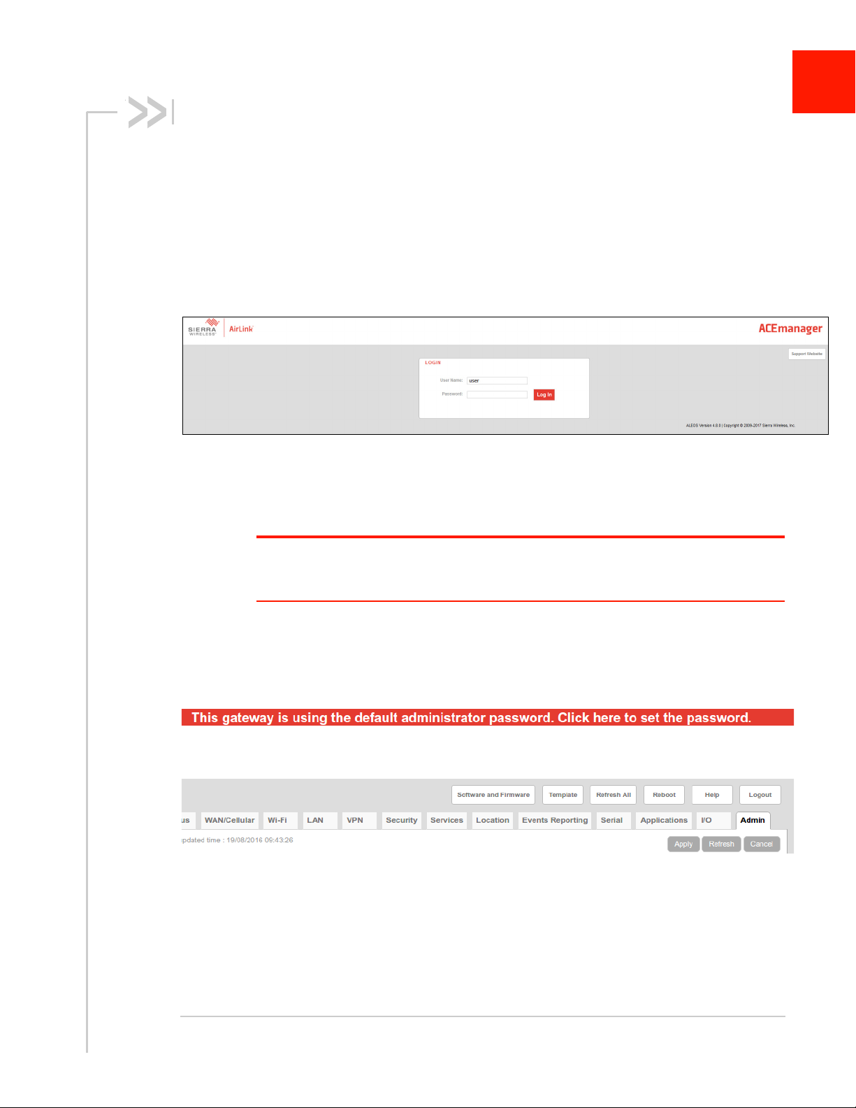
Figure 2-1: ACEmanager: Main Login screen
4. Log in:
· User Name: “user” (entered by default)
· Default Password: 12345
2
Note: ACEmanager sessions, by default, time out in 15 minutes. If there is no activity for this
idle timeout period, you are redirected to the Login screen. To change the session idle timeout
period, see Session Idle Timeout (minutes) on page 171.
To prevent others from changing the AirLink gateway settings, you can change the
ACEmanager password (see Change Password on page 307).
If the gateway is using the default password, a banner at the top of the screen
reminds you to change it.
Click the banner to go to the Change Password screen.
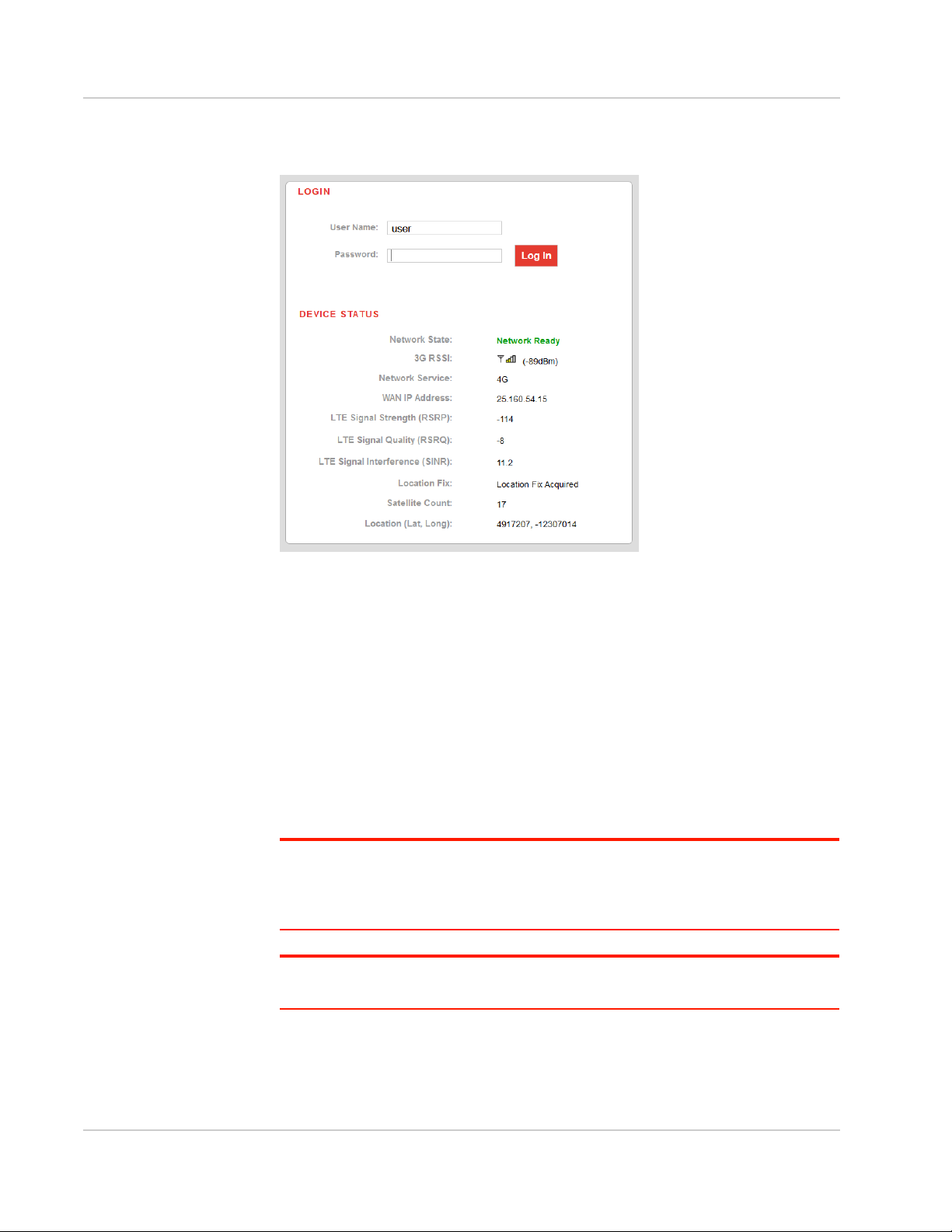
After your initial log in to ACEmanager, you have the option of displaying the gateway
status parameters on subsequent Login screens.
5. In ACEmanager, go to Services > Device Status Screen.
Rev 1 Dec. 17 14 41111088
Page 15
Gateway Configuration
6. In the Device Status on Login Screen field, select Enable. (For details, see
Device Status Screen on page 223.)
Figure 2-2: ACEmanager: Main Login screen with Location and Device Status enabled.
If you have Location fields selected on the Device Status screen, but Location
Service is disabled, the gateway Login screen will show Location Service
Disabled.
Recovery Mode
In the unlikely event that ALEOS becomes corrupted, or, if the gateway is
unresponsive to ACEmanager input and AT commands, you can manually put the
gateway into recovery mode.
Recovery mode enables you to update the ALEOS software and return the
gateway to working order.
Note: To use Recovery Mode, you must update older gateways to ALEOS 4.7.0 or later
and use the *RCVRUPDATE command (see page 400) to install the recovery mode
manager. These steps must be done while the gateway is operating normally. For
gateways shipped from the factory with ALEOS 4.8.0, no action is required.
Note: ALEOS software updates done in Recovery mode do not preserve any custom
setting such as cellular settings, AAF applications, etc.
To enter Recovery mode:
1. Use an Ethernet cable to connect the gateway to your computer. (Recovery
mode is not supported on USBnet.)
Rev 1 Dec. 17 15 41111088
Page 16
ALEOS 4.9.0 Software Configuration User Guide for AirLink RV50 Series
2. Power on the AirLink gateway.
3. On the gateway, press the Reset button for more than 20 seconds. (Release
the button when the Power LED flashes amber.)
4. Launch your browser and enter the IP address and port number
http://192.168.13.31:9191.
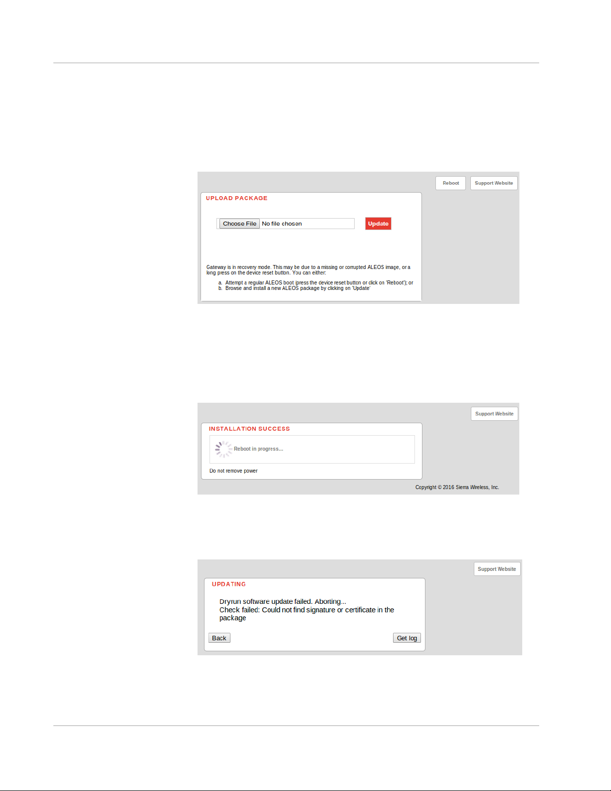
The following screen appears:
Figure 2-3: Recovery screen
5. Click Choose File and navigate to the appropriate ALEOS software version
for your gateway.
6. Click Update.
The screen lets you know that the update was successful and automatically
reboots the gateway.
When the reboot is complete, the gateway exits Recovery mode, and the
ACEmanager Login screen appears.
If you select an inappropriate version of ALEOS, an error message, such as
the following appears.
If this happens, click the Log button and save the log file for review by Sierra
Wireless or your authorized reseller.
Rev 1 Dec. 17 16 41111088
Page 17

Gateway Configuration
Click Back to return to the previous screen to select the correct version of
ALEOS.
If you have inadvertently entered Recovery mode, you can exit it by doing one of
the following:
• Press the reset button on the gateway to reboot it.
• Click the Reboot button on the Recovery screen.
• Wait 10 minutes. If no action is taken within 10 minutes of the device entering
Recovery mode (for example, if the Recovery screen has not been loaded by
the web browser), it automatically reboots and exits Recovery mode.
Toolbar
The buttons on the ACEmanager toolbar are:
• Software and Firmware: Updates the ALEOS software and the radio module
firmware
• Template:
· Download and save a configuration as a template
· Upload a saved template to apply settings
• Reboot: Reboots the gateway
• Refresh All: Refreshes all ACEmanager pages
• Help
• Logout
Configuring your AirLink Gateway
There are three options for configuring the AirLink gateway:
• Use your browser-based ACEmanager (as detailed in this guide)
• Use a terminal emulator application (e.g., Tera Term, PuTTY, etc.) to enter
AT commands for many of the configuration options.
• Use the cloud-based AirLink Management Service application (see
www.sierrawireless.com/products-and-solutions/gateway-solutions/alms/ for
more details.)
Saving a Custom Configuration as a Template
If you have a gateway configured to match your requirements, you can use
ACEmanager to download and save that gateway’s configuration as a template
and then apply it to other Sierra Wireless AirLink gateways.
Note: Sierra Wireless recommends that templates be created and applied to AirLink
gateways running the same version of ALEOS. If you apply a template created using an
older version of ALEOS to a gateway running a newer version of ALEOS, settings for
newly added features are not updated.
Rev 1 Dec. 17 17 41111088
Page 18
ALEOS 4.9.0 Software Configuration User Guide for AirLink RV50 Series
To download and save a custom configuration as a template:
1. Connect a laptop to the gateway with the configuration you want to save as a
template.
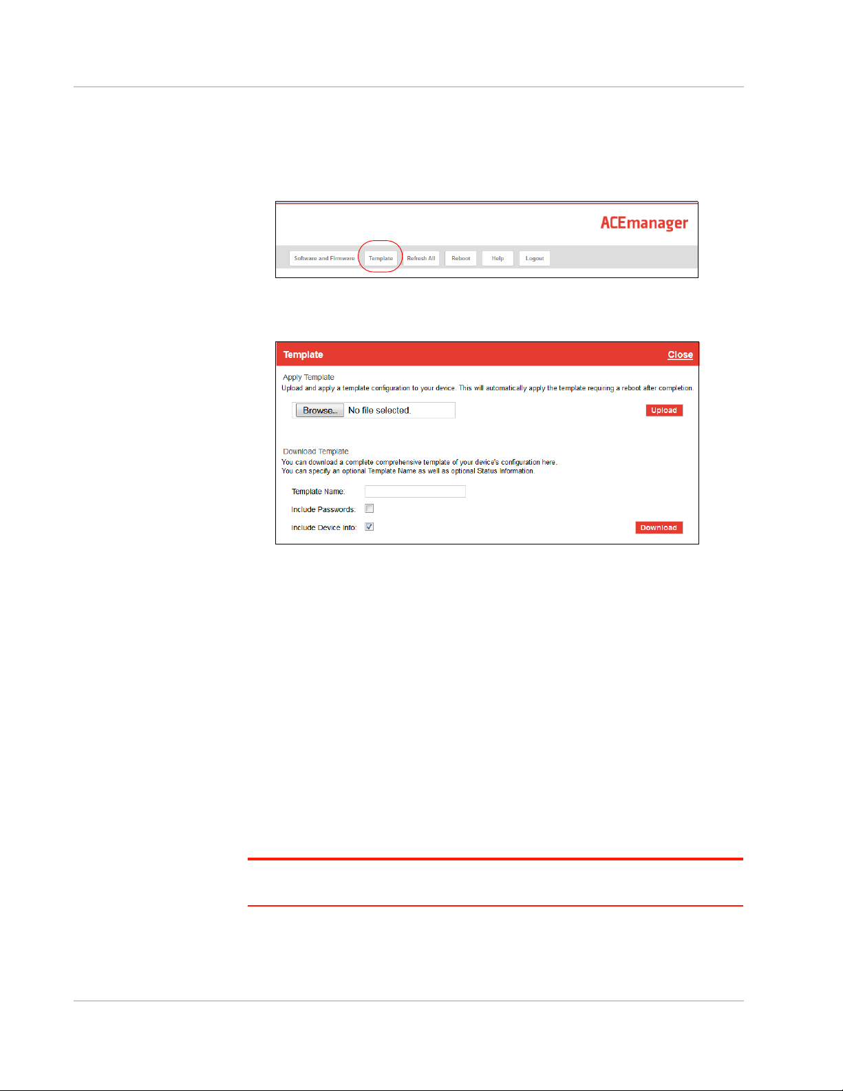
2. In ACEmanager, click the Template button on the toolbar.
Figure 2-4: ACEmanager: Template button
The following window appears:
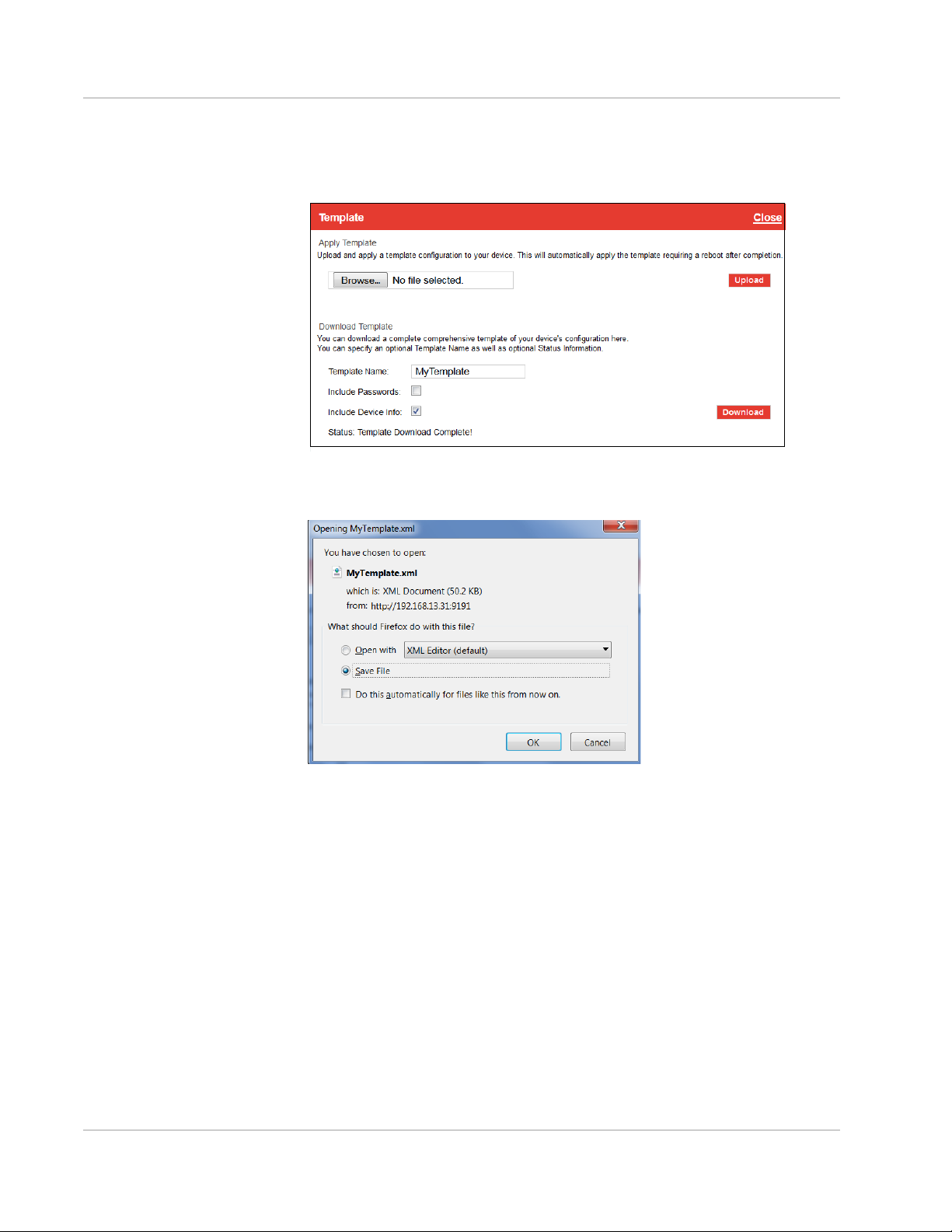
Figure 2-5: ACEmanager: Template window
Use the bottom half of the window to download and save a template.
3. If desired, enter a Template Name. The file is saved using this name and a
.xml file extension. Spaces and special characters are not supported, and if
entered, are deleted from the file name.
If no Template name is entered, the file is saved as SWIApplyTemplate.xml.
4. Choose whether or not to:
· Include Passwords
When Include Passwords is selected, passwords configured in ACEmanager (such as the email password, the SMS ALEOS Command password,
the Serial PPP password, etc.) are shown in plain text in the template file.
When the template is uploaded to a gateway, the passwords are included
and replace any existing password configured on the gateway.
If Include Passwords is not selected, password fields are not included in the
template file, and existing passwords persist when the template is uploaded
to a gateway.
Note: The ACEmanager login password is not included when you select the Include
Passwords option.
· Include Device Info (selected by default)
When selected, the template file includes a “snap-shot” of the current
Rev 1 Dec. 17 18 41111088
Page 19
Gateway Configuration
Status tab information with the current settings. This could be useful for
troubleshooting.
5. Click Download. The download status appears at the bottom of the window.
Figure 2-6: Download template complete
Once the download is complete, the following window opens:
Figure 2-7: Open or Save the template file
6. In most cases, you will want to save the file to your computer for uploading to
other AirLink gateways, but you also have the option to open the file.
· Select Save File and click OK—file is saved to your computer (by default to
the Downloads folder). If you entered a template name, the file is saved
using that name. Otherwise, it is saved under the default name,
SWIApplyTemplate.xml.
· Select Open and click OK— file opens in a text or XML editor as a human
readable file. Use this option if you selected Include Device Info when you
saved the file and want to view the device information (the text between the
<devicestatus> and </devicestatus> tags is the snap-shot of the Device
Info), or you want to compare this template with another template.
Rev 1 Dec. 17 19 41111088
Page 20

ALEOS 4.9.0 Software Configuration User Guide for AirLink RV50 Series
Warning: Do not attempt to change settings directly in the template file. Changing
settings in the template file could result in unexpected behavior in the AirLink gateway.
Alter the template only if you are specifically directed to do so by your distributor or Sierra
Wireless Technical Support.
Tip: If you want to compare a new template with the previous one, download and save the
old template before applying the new one. You can use any 3rd party text comparison tool
to check the differences between two templates.
Applying a Template
Note: If you are using Internet Explorer 9 to upload the template, see Te mpl at es on
page 474 for instructions on configuring the browser’s Internet options to allow the upload.
To upload and apply a template to an AirLink gateway:
1. Connect the computer (where the template is saved) to the AirLink gateway
you want to upload the template to, or connect to the gateway over the air.
2. Log in to ACEmanager, and go to Admin > Advanced.
Note: Sierra Wireless
recommends resetting the
gateway to the factory
default settings before
applying the template.
3. Select the Reset Mode:
· Preserve Cellular Authentication Settings—Recommended if you are
applying a template remotely using a remote ACEmanager connection (or
ALMS). For a list of preserved settings, see Reset Mode on page 319.
· Reset All— Recommended if you are applying a template locally (i.e your
computer is physically connected to the gateway).
4. Once the gateway reboots, log in to ACEmanager.
5. In ACEmanager, click the Template button on the toolbar.
Figure 2-8: ACEmanager: Template button
Rev 1 Dec. 17 20 41111088
Page 21
Gateway Configuration
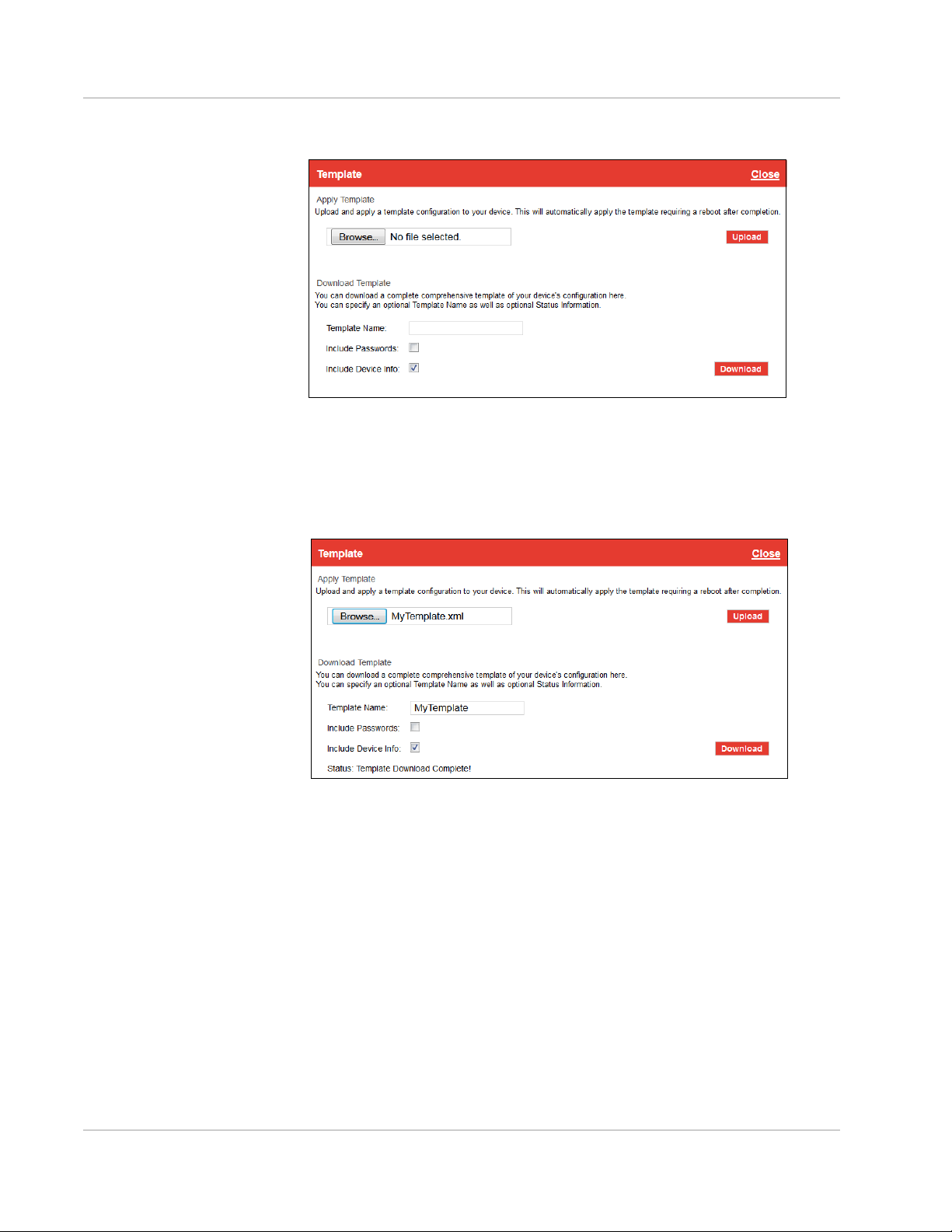
The following window appears:
Figure 2-9: ACEmanager: Template window
Use the top half of the window to upload and apply a template to your AirLink
gateway.
6. Click Browse... and navigate to the template you want to upload.
7. Click Open. The template file name appears beside the Browse... button.
Figure 2-10: Apply Template file opened
8. Click Upload.
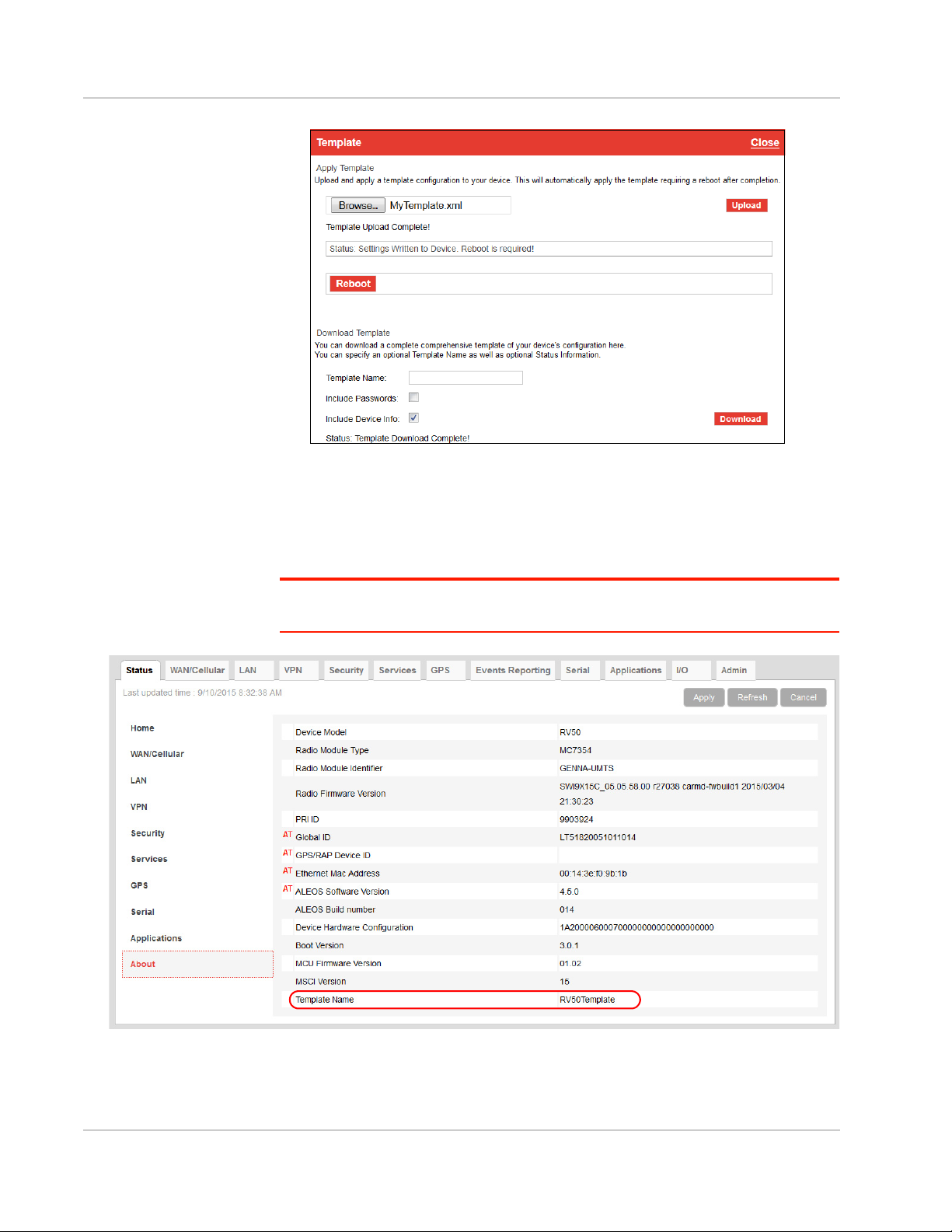
9. When the upload is complete, a Reboot button appears on the window.
Rev 1 Dec. 17 21 41111088
Page 22
ALEOS 4.9.0 Software Configuration User Guide for AirLink RV50 Series
Figure 2-11: Template file uploaded
10. Click Reboot.
11. To confirm that the new template has been applied or to find out which
template is currently on a gateway, go to Status > About and check the
Template Name field.
Note: The Template Name field shows the last template applied and does not indicate any
configuration changes made since the last template was applied.
Figure 2-12: ACEmanager: Status > About
Rev 1 Dec. 17 22 41111088
Page 23

Gateway Configuration
Note: If no template has been applied to the gateway since it was set or reset to the
factory default settings, the template field is blank.
Update the ALEOS Software and Radio Module Firmware
To take advantage of new features available in the latest version of ALEOS,
update the ALEOS software and radio module firmware on your AirLink gateways.
Important: Once the gateway has been upgraded to ALEOS 4.7.0, you cannot
downgrade to earlier versions of ALEOS.
You can use ACEmanager to update one gateway at a time or AirLink
Management Service (ALMS) to update one or multiple gateways at the same
time.
Note: If the update includes a radio module firmware update, the radio module firmware
stored on the gateway is also automatically updated. If there is not enough room in the
storage, the radio module firmware update fails, so you may need to remove one of the
versions stored on the gateway to free up space. For more information, see Radio Module
Firmware on page 326.
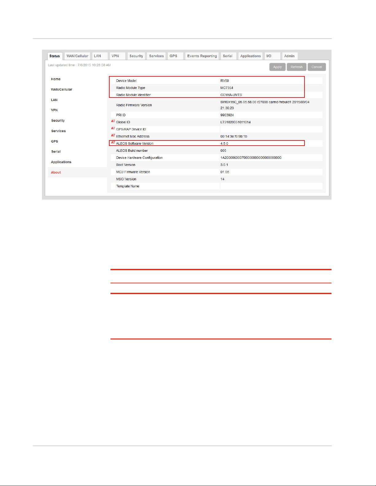
Step 1—Planning Your Update
1. Sierra Wireless recommends that you download a template from the
gateway(s) before you begin the update process. For instructions, see Saving
a Custom Configuration as a Template on page 17.
2. For each of the gateways you want to update, make a note of the:
· Device Model
· Radio Module Type
· Radio Module Identifier
ALEOS Software Version This information is available in ALMS and in ACEmanager (Status > About).
Figure 2-13:
Rev 1 Dec. 17 23 41111088
Page 24
ALEOS 4.9.0 Software Configuration User Guide for AirLink RV50 Series
Figure 2-14: ACEmanager: Status > About
3. If you are planning to use ACEmanager to do the update:
a. Go to source.sierrawireless.com and select your product and mobile
network operator to get to the download page for your gateway.
b. Download the new ALEOS software version for your system. If new radio
module firmware is available, it is included with the ALEOS software in a
.zip file.
Important: Do not install radio module firmware unless you are prompted to do so.
Note: If low power mode or time of day reboot areconfigured, and the following events
arelikely to coincide with the update:
• The gateway entering low power mode
• The Time of Day reset occurring
Sierra Wireless recommends that you disablethese features before beginning the update.
Recommendations
If you have any questions about the update process, contact your authorized
Sierra Wireless distributor before updating the radio module firmware.
Scheduling the update
The update can take up to 30 minutes to complete, depending on the speed of
your network connection. The AirLink gateway being updated will be off-line
during the update, so take this into account when scheduling the update.
Rev 1 Dec. 17 24 41111088
Page 25

Gateway Configuration
Important: BE PATIENT! The firmware update can take up to 30 minutes to complete.
Waiting for the process to complete is faster than troubleshooting the problems that can be
caused by interrupting the process midway. (Interrupting the process may result in having
to return the gateway to the factory for repairs.)
Step 2—Update the ALEOS Software and Radio Module Firmware
Using ACEmanager to Update a Single AirLink Gateway
To update the ALEOS software and radio module firmware on one AirLink
gateway:
1. Connect the AirLink gateway you want to update to your laptop, launch your
browser and enter the URL for the gateway. The default IP address/port for
the Ethernet interface is http://192.168.13.31:9191. If it is a remote gateway,
enter the domain name or public IP (WAN) address.
Note: If you are connected to the gateway remotely, any files transferred to the gateway
are transferred over-the-air and you may incur data charges.
2. Log in to ACEmanager.
Default user name: user
Default password: 12345
3. Click the Software and Firmware link.
The Software and Firmware update window opens.
Note: These instructions show typical Software and Firmware update windows. Details
such as the ALEOS version, device model, radio firmware version, etc. may vary,
depending on the gateway you are updating.
Figure 2-15:
Rev 1 Dec. 17 25 41111088
Page 26
ALEOS 4.9.0 Software Configuration User Guide for AirLink RV50 Series
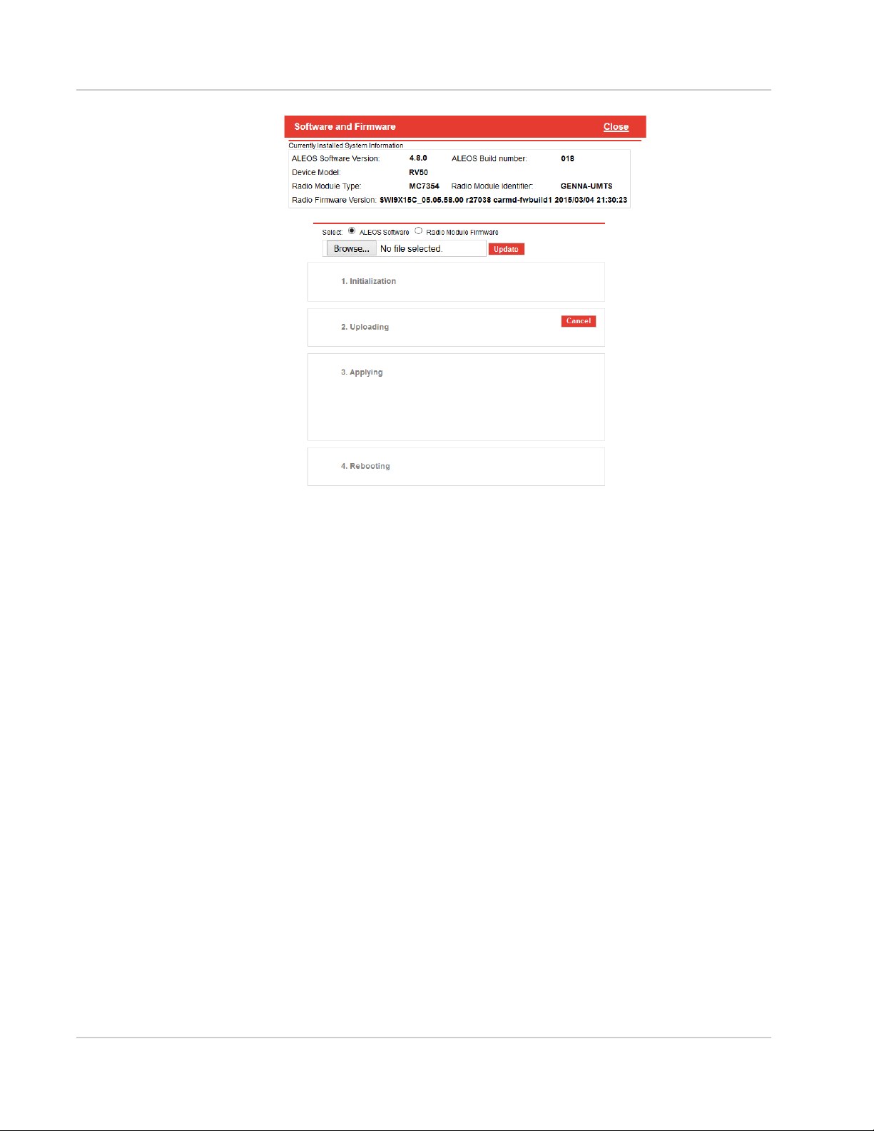
Figure 2-16: Software and Firmware update window
The update window gives you the option to update both ALEOS and the radio
module firmware, or update only the radio module firmware.
Unless advised otherwise by Sierra Wireless, select ALEOS software (which
updates ALEOS and prompts you to update the radio module firmware if a newer
version is available for your gateway).
4. Click Browse... and navigate to the ALEOS software you downloaded from
the Sierra Wireless Web site. This is a .bin file named for the gateway and the
ALEOS software version. For example, RV50_4.6.1.014.bin.
Figure 2-17:
Rev 1 Dec. 17 26 41111088
Page 27

Gateway Configuration
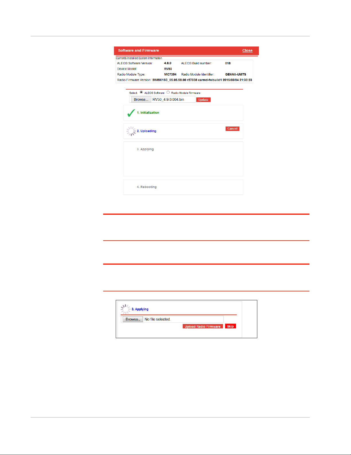
Figure 2-18: ALEOS file selected in Software and Firmware update window
5. Click Update.
The ALEOS software update runs automatically and green check marks
appear beside each step as it is completed.
Figure 2-19:
Rev 1 Dec. 17 27 41111088
Page 28
ALEOS 4.9.0 Software Configuration User Guide for AirLink RV50 Series
Figure 2-20: ALEOS software update in progress
Important: Do not disconnect the AirLink gateway from the computer, and do not power
cycle or reset the gateway during the update. If you see any error messages, refer to the
Updating the ALEOS Software and Radio Module Firmware on page 475.
6. Depending on the gateway and your Mobile Network Operator, you may be
prompted to update the radio module firmware.
If you do not receive a prompt, the radio firmware is up to date. Proceed to
step 9.
Only if prompted to update the firmware, proceed to step 9.
Figure 2-21: Prompt for Radio Module Firmware
7. Under Applying, click Browse... and navigate to the radio module firmware file
that was included in the .zip file you downloaded. This is an .iso file named for
the gateway’s radio module and the mobile network operator’s network (or
“GENERIC”, if it is intended for more than one operator network). For
example, MC7354_GENERIC_2820.iso.
8. Click Upload Radio Firmware.
Rev 1 Dec. 17 28 41111088
Page 29
Gateway Configuration
A message appears on the window indicating that the firmware has been successfully uploaded.
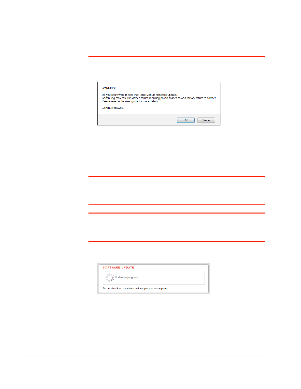
Note: Sierra Wireless recommends that you do NOT skip the radio module firmware
update unless advised to do so by Sierra Wireless or an authorized distributor. If you
choose to skip the radio module firmware update, you’ll see the following warning.
Once the radio module firmware is uploaded, the gateway begins applying the
firmware upgrade. On the AirLink gateway, the LED chase begins to indicate
that the firmware is being applied.
As indicated on the window, the radio module firmware may take 10 to 20 minutes to upload and install.
Important: Do not disconnect the AirLink gateway from the computer or reboot the
gateway while the firmware update is in progress. During the radio module firmware
update, the gateway LEDs flash rapidly in sequence (an LED chase or caterpillar). When
the radio module firmware update is complete, the gateway reboots automatically.
Note: When you update the radio module firmware, the firmware stored on the gateway is
also updated. If there is not enough room in the storage, the radio module firmware update
fails. In that case, first remove one of the versions stored on the gateway to free up space.
For more information, see Radio Module Firmware on page 326.
9. When the update is complete, the AirLink gateway reboots. The Software
Update progress window appears.
When the reboot is complete, you are returned to the Login screen.
10. After you log in, go to Status > About.
11. Click Refresh.
12. Check the ALEOS Software Version and the Radio Firmware Version fields to
confirm that the ALEOS software and the radio module firmware have been
updated.
Rev 1 Dec. 17 29 41111088
Page 30
ALEOS 4.9.0 Software Configuration User Guide for AirLink RV50 Series
Using AirLink Management Service (ALMS) to Update One or
Multiple AirLink gateways Over-the-Air
You can use AirLink Management Service to update the ALEOS software and
radio module firmware over-the-air on one or multiple AirLink gateways.
If you don’t have an ALMS account:
1. In ACEmanager, go to the Services tab and ensure that ALMS is enabled and
the server URL is https://na.m2mop.net/device/msci/com
case, enter the correct URL, click Apply and then click Reboot.
2. Go to www.sierrawireless.com/ALMS for more information.
Updating to ALEOS software with an ALMS account:
1. Go to airvantage.net and log in.
2. Follow the instructions in the online ALMS documentation to update the
ALEOS software and radio module firmware.
Updating Only the Radio Module Firmware
Important: This feature should be used only if directed by Sierra Wireless or an autho-
rized reseller.
.
If this is not the
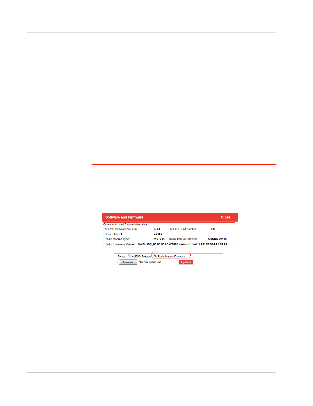
If Sierra Wireless or your authorized reseller directs you to update only the Radio
Module Firmware:
1. Select the Radio Module Firmware button.
2. Select the appropriate firmware file for your gateway and click Update. This is
an .iso file named for the gateway’s radio module and the mobile network
operator’s network (or “GENERIC”, if it is intended for more than one operator
network). For example, MC7354_GENERIC_2820.iso.
If you select a file for radio module firmware that is not supported on your
gateway, you will see a warning message similar to the following:
Rev 1 Dec. 17 30 41111088
Page 31

Gateway Configuration
host
AirLink gateway
Unless you have been advised by Sierra Wireless to do so, we recommend
that you do not install an unsupported version of the radio module firmware.
3. Click Update.
The radio module firmware update runs automatically and green check marks
appear beside each step as it is completed.
4. When the update is complete, the AirLink gateway reboots. The Software
Update progress window appears.
When the reboot is complete, you are returned to the Login screen.
5. After you log in, go to Status > About.
6. Check the Radio Firmware Version has been updated.
Enterprise LAN Management
You can use AirLink gateways in the following configurations:
• Standalone with a connection to a single device
When using the AirLink gateway with a single device, ensure that the device is
DHCP enabled.
• With a router
The router allows several devices to use the AirLink gateway’s connection to
the network. When using the AirLink gateway with a router:
· Configure the router to be DHCP enabled.
And either:
· Configure the router to use Network Address Translation (NAT).
Or
Rev 1 Dec. 17 31 41111088
Page 32

ALEOS 4.9.0 Software Configuration User Guide for AirLink RV50 Series
hosts
AirLink gateway
Router
· Configure ALEOS (in ACEmanager) to use Host Port Routing. For infor-
mation on using ALEOS with a router that is not configured to use NAT, see
Host Port Routing on page 120.
Note: Other than for VLANs, ALEOS does not provide DHCP addresses to router
connected devices.
Over the Air (OTA) Connections
Access AirLink gateways
You can use an OTA connection to access AirLink gateways that are in either
configuration described above (stand alone or with a router).
Access connected devices
To use an OTA connection to access a connected device through the AirLink
gateway, configure the device in ALEOS as the DMZ or port forwarding
destination. For information on inbound OTA connections to the host, see DMZ on
page 158 and Port Forwarding on page 153.
Configuring Your Gateway for use in a PCI Compliant System
The credit card industry requires retailers to comply with Payment Card Industry
(PCI) standard to maintain a secure environment when processing payment card
transactions. For these transactions, the AirLink gateway acts as a wireless data
conduit for routers and PoSs (point-of-sale-terminals) that have been configured
for PCI compliance.
Rev 1 Dec. 17 32 41111088
Page 33

Gateway Configuration
AirLink gateway
Payment Processor
DSL Gateway
Internet
Router configured for
Retail store
Wi-Fi
LAN
LAN
Cellular WAN
WAN
PoS
Wireless Access Point
PoS
PCI compliance
Figure 2-22: Sample PCI compliant network
The PCI compliant network must be set up so that:
• The USBnet is on a different subnet from the point-of-sale-terminal.
• All security protocols must be established from the point-of-sale terminal to
the payment processor.
• Payment card terminals must be on a dedicated LAN or VLAN.
• The AirLink gateway must be connected to a router that is configured for PCI
compliance.
Note: The serial port on the AirLink gateway has no access to the IP data path and does
not need to be disabled.
If you are using the AirLink gateway for a payment card industry application, to
meet PCI Data Security Standard compliance requirements the following steps
must be done by a PCI certified service company.
For each gateway:
1. Connect the AirLink gateway to a router that has been configured for PCI
compliance.
2. Log in to ACEmanager. (User name is user; default password is 12345.)
Change the password regularly, in accordance with PCI recommendations.
3. Go to the Admin tab and change the default password.
Do not share the ACEmanager password.
4. Go to Applications > ALEOS Application Framework and set the ALEOS
Application Framework field to Disable.
Rev 1 Dec. 17 33 41111088
Page 34

3: Status
All fields in the Status group are read-only and provide information about the AirLink
gateway. Depending on individual settings and the onboard radio module, the actual
status pages may look different than the screen shot shown here.
Tip: To be sure you are viewing the current status for all fields, click the Refresh button on the
upper right side of the screen.
Home
The Home section of the Status tab is the first page displayed when you log in to
ACEmanager. It shows basic information about the WAN network connection, the
mobile network connection, and important information about the gateway.
Note: The fields displayed vary depending on the gateway, the radio module, the type of
network the gateway is connected to, and ACEmanager settings. For details, see Table 3-1 on
page 37.
3
Figure 3-1: ACEmanager: Status > Home
Rev 1 Dec. 17 34 41111088
Page 35

Field Description
General
Status
Active WAN IP
Address
Network State Current state of the WAN network connection
The current IPv4 WAN IP address for the gateway
• Network Ready—Connected to a mobile broadband network and ready to transfer data
• Connected —No Service
• Not Connected
Network Interface Current active network interface
Customer Device
Name
Device Uptime Length of time since the gateway last rebooted (in days, hours, and minutes)
Advanced (DNS)
DNS Proxy Determines which DNS server the connected clients use for domain name resolution
By default, the name is the serial number of the gateway. If you have configured a device name
in the IP Manager section of the Services > Dynamic DNS tab, that name appears in this field.
• Enabled—DNS Proxy is activated. Connected DHCP clients acquire the AirLink gateway's
IP address as their DNS server. The AirLink gateway performs DNS lookups on behalf of
the clients.
• Disabled —Connected DHCP clients acquire the DNS servers used by the gateway.
To set this option, see DNS Proxy on page 123.
DNS Cache Status of the DNS Local Cache feature
• Enabled—The built-in DNS server caches queries and entries, which can reduce WAN
traffic overall by sending out less DNS-related traffic.
• Disabled—DNS queries and entries are not cached.
• To set this option, see DNS Local Cache on page 124.
DNS Override Override WAN-granted DNS
• Enabled—Locally configured DNS servers are used.
• Disabled—DNS servers provided by the active WAN connection are used.
DNS Server 1
(IPv4)
DNS Server 2
(IPv4)
1st DNS server IP address currently in use by the WAN connection to resolve domain names
into IP addresses
2nd DNS server IP address
Cellular
The Cellular section provides specific information about the connection including
the IP address and how much data has been transmitted or received. Some of the
information on this screen is repeated on the Home page for quick reference.
Rev 1 Dec. 17 35 41111088
Page 36

ALEOS 4.9.0 Software Configuration User Guide for AirLink RV50 Series
Figure 3-2: ACEmanager: Status > Cellular
Rev 1 Dec. 17 36 41111088
Page 37

Table 3-1: Reported Signal Strength and Quality Values
Network Signal Strength and Quality values
Status
EV-DO, 1x
(RV50 only)
• Signal Strength (RSSI)
• Signal Quality (ECI0)
• Received Signal Power Code (RSCP)
• LTE Signal Interference (SINR Level)
UMTS • Signal Strength (RSSI)
• Signal Quality (ECI0)
• Received Signal Power Code (RSCP)
LTE • Signal Strength (RSSI)
• LTE Signal Strength (RSRP)
• LTE Signal Quality (RSRQ)
• LTE Signal Interference (SINR)
General
Phone Number The phone number associated with the Mobile Network Operator account. If the Mobile Network
Operator does not allow the account to display the phone number or there is no Mobile Network
account for the gateway, “NA” is displayed.
Cellular IP
Address
Cellular State Current state of the cellular connection:
IPv4 Cellular WAN IP Address
If there is no mobile network connection, 0.0.0.0 is displayed.
• Connected
• Not Connected
• No Service
Rev 1 Dec. 17 37 41111088
Page 38

ALEOS 4.9.0 Software Configuration User Guide for AirLink RV50 Series
Cellular State
Details
Provides additional details about the current cellular state, for example the gateway may not be
connected because the SIM card is not installed. Possible messages are:
• Disconnected
• Connecting
• Data connection failed. Waiting to retry
• Not Connected - Radio Connect off
• Not Connected - Waiting for Activity
• No SIM or Unexpected SIM Status
• SIM Locked, but bad SIM PIN
• SIM PIN Incorrect, 5 Attempts Left
• SIM PIN Incorrect, 4 Attempts Left
• SIM PIN Incorrect, 3 Attempts Left
• SIM PIN Incorrect, 2 Attempts Left
• SIM PIN Incorrect, 1 Attempt Left
• SIM PIN Incorrect, 0 Attempts Left
• SIM Blocked, Bad unlock code
• SIM Locked: 10 PUK Attempts Left
• SIM Locked: 9 PUK Attempts Left
• SIM Locked: 8 PUK Attempts Left
• SIM Locked: 7 PUK Attempts Left
• SIM Locked: 6 PUK Attempts Left
• SIM Locked: 5 PUK Attempts Left
• SIM Locked: 4 PUK Attempts Left
• SIM Locked: 3 PUK Attempts Left
• SIM Locked: 2 PUK Attempts Left
• SIM Locked: 1 PUK Attempt Left
• SIM Blocked, unblock code incorrect
• IP Acquired
Cellular End-to-
End Connection
Describes the state of the cellular network connection, based on Cellular network monitoring
(see Cellular > Monitor on page 86). Possible states are:
• Not Verified—The monitoring function is set to disable and therefore the availability of the
cellular network cannot be verified.
• Pending—The monitoring function is enabled, but has not yet completed its test. Once the
first test is complete, this option only appears again if monitoring is disabled and then reenabled.
• Established—The monitoring system has determined that service is available on the
cellular network.
• Not Established—The monitoring system has determined that the cellular interface has no
service (ping test failed).
Carrier
Availability
Indicates whether or not the mobile network operator (carrier) is able to provide service to the
gateway’s radio module
Possible values:
• Available
• Not Available
SIM Network
Operator
The SIM card’s home network, i.e, the Mobile Network Operator when the gateway is not
roaming
Rev 1 Dec. 17 38 41111088
Page 39

Status
RSSI Signal strength
> -78 dBm Good
-78 dBm to -93 dBm Fair
-94 dBm to -102 dBm Poor
< -103 dBm Inadequate
ECI0 Signal quality
0 to -6 Good
-7 to -10 Fair
-11 to -20 Poor
Serving Network
Operator
Signal Strength
(RSSI)
Signal Quality
(ECI0)
The network currently in use
This field only appears when the gateway has a network connection.
• If the gateway is not roaming, this field is the same as the SIM Network Operator field.
• If the gateway is roaming, this field displays the roaming Mobile Network Operator.
Received Signal Strength Indicator
The average received signal power measured in the air interface channel
Indicates if there is a strong signal available for the AirLink gateway to connect to
See also LTE Signal Strength (RSRP) and LTE Signal Quality (RSRQ).
The value varies, depending on the network characteristics and the AirLink gateway.
2G/3G signal quality
Indicates the signal quality with a ratio of the average signal energy to co-channel interference in
dB
ESN/EID/IMEI Electronic Serial Number for the internal radio
SIM ID Identification number for the SIM card in use
APN Status Current APN in use by the network connection
• (Configured) is a default APN based on the SIM card in use.
• (User Entered) is a custom APN entered manually into the configuration.
Note: APN is configured on the WAN/Cellular configuration tab.
Number of SIMs
present
Primary SIM Indicates which SIM card slot contains the primary SIM card. If two SIM cards are installed, the
Active SIM Indicates which SIM slot contains the Active SIM card (The SIM card that is used for the current
Rev 1 Dec. 17 39 41111088
Indicates the number of SIM cards present in the gateway
Primary SIM card is used for network connections.
data connection.)
Page 40

ALEOS 4.9.0 Software Configuration User Guide for AirLink RV50 Series
Radio Technology Type of service being used by the gateway (e.g. LTE, HSPA+, 1xRTT, EV-DO, UMTS, HSPA,
Network Service
Type
Network
Connection Type
Active Frequency
Band
Statistics
Bytes Sent Number of bytes sent to the mobile network since system startup or reboot
Bytes Received Number of bytes received from the mobile network since system startup or reboot
Persisted Bytes
Sent
Persisted Bytes
Received
EDGE, or GPRS)
If you are connected to a network other than that of your Mobile Network Operator, the network
service type indicates that you are roaming (and additional charges may apply).
Type of network the gateway is connected to (e.g. 4G, 3G, 2G)
This field only appears if the IP Address Preference field on the WAN/Cellular tab is set to IPv4
and IPv6 Gateway.
Displays the type of IP connection that has been established
(None, IPv4, or Both IPv4 and IPv6)
Current cellular band being used (LTE BAND 4, WCDMA 2100, etc.)
Number of bytes sent
The count starts when the gateway first goes on air and persists over reboot. The field resets to
zero on reset to factory default settings.
For the RV50 Series, this value is the cumulative traffic for both SIM cards, if more than one SIM
card is present.
Number of bytes received
The count starts when the gateway first goes on air and persists over reboot. The field resets to
zero on reset to factory default settings.
For the RV50 Series, this value is the cumulative traffic for both SIM cards, if more than one SIM
card is present.
Packets Sent Number of packets sent to the network since system startup or reboot
Packets Received Number of packets received from the network since system startup or reboot
Monitor
Test Interval
(minutes)
Monitor Type The configured type of test being run on the interface to diagnose its ability to provide end-to-
Ping Test IP
Address
Time Between
Pings (seconds)
Cellular Network
Watchdog
Current WAN
Time in Use
(minutes)
The configured amount of time between tests of the cellular connection
end connectivity
The configured IP address used for testing interface connectivity
The configured time between individual pings
Status of the Cellular Network Watchdog (Enabled or Disabled)
See Network Watchdog on page 66.
The length of time the cellular WAN has been in use
Rev 1 Dec. 17 40 41111088
Page 41

Status
Advanced
IMSI International Mobile Subscriber Identity number
Cell ID Unique number that identifies each base transceiver station (BTS) or sector of a BTS within an
LAC
LAC / TAC Location Area Code or Tracking Area Code (LTE)
BSIC Base Station Identity Code
Carrier
Aggregation
Indicator
PN Offset Applies to RV50 Only
Dynamic Mobile Network Routing (DMNR) is only supported on the Verizon Wireless network.
DMNR Status DMNR status:
Applies only to LTE-Advanced networks
Indicates whether or not carrier aggregation is enabled
Base station identifier used in CDMA networks
• Enabled
• Disabled
DMNR Foreign
Agent
Registration
Status
This field only appears if DMNR is enabled.
The status of transactions with the Home agent
• Pass —Connected subnets registered or de-registered successfully
• Fail—Unable to register or de-register connected subnets
• Unknown
DMNR Reverse
Tunnelling Agent
Status
This field only appears if DMNR is enabled.
Status of the NEMO tunnel
• Up
• Down
Cell Info Cell information such as the Base Station Identity Code (BSIC), TCH, Received Signal Strength
Indicator (RSSI), Location Area Code (LAC), and the cell ID
For additional information, including cell info for LTE networks, see *CELLINFO2? on page 401
and LTE Net works on page 478.
Signal Strength and Quality
Different radio technologies have different ways of reporting signal strength and signal quality. The fields displayed in
ACEmanager depend on the type of network it is connected to. For details, see Reported Signal Strength and Quality
Values on page 37.
Received Signal
Code Power
(RSCP)
The RSCP is the power measured by the receiver on a particular physical channel. It provides
an indication of signal strength for CDMA and UMTS connections. Expected values are in the
range of -50 dB to -120 dB.
Rev 1 Dec. 17 41 41111088
Page 42

ALEOS 4.9.0 Software Configuration User Guide for AirLink RV50 Series
RSRP Signal strength
> -95 dBm Good
-95 dBm to -115 dBm Fair
-116 dBm to -1000 dBm Poor
< -1000 dBm Inadequate
RSRQ Signal quality
> -9 dB Good
-9 dB to -12 dB Fair
< -12 dB Poor
LTE Signal
Strength (RSRP)
LTE Signal
Quality (RSRQ)
Reference Signal Received Power
The average signal power of all cell-specific reference signals within the LTE channel
Indicates whether the AirLink gateway has a strong connection to the wireless network
The value varies, depending on the network characteristics and the AirLink gateway.
See also LTE Signal Quality (RSRQ) and Signal Strength (RSSI).
Reference Signal Received Quality
The RSRQ indicates the quality of the AirLink gateway’s connection to the wireless network. (Is
noise or interference affecting the quality of the connection?) See also Signal Strength (RSSI)
and LTE Signal Strength (RSRP).
The value varies, depending on the network characteristics and the AirLink gateway.
Note: For additional information on the LTE network, use the *CELLINFO2? AT command
(described on page 401).
LTE Signal
Interference
(SINR Level)
Signal Interference Plus Noise (SINR) Level only applies to Sprint and Verizon Wireless LTE
networks. The maximum value for each level is:
• Level 0 = -9 dB
• Level 1 = -6 dB
• Level 2 = -4.5 dB
• Level 3 = -3 dB
• Level 4 = -2 dB
• Level 5 = +1 dB
• Level 6 = +3 dB
• Level 7 = +6 dB
• Level 8 = +9 dB
Rev 1 Dec. 17 42 41111088
Page 43

Status
SINR Throughput
> 10 Excellent
6–10 Good
0–5 Fair
< 0 Poor
LTE Signal
Interference
(SINR)
Channel WAN network channel
Network Operator
Switching
Signal to noise and interference ratio
Higher values indicate that signal power is much greater than noise and interference.
The current active channel number for the mobile network connection
Network Operator Switching status (See Radio Module Firmware on page 326.) Possible status:
• OK—The SIM in use matches the currently active radio module firmware.
• Manually disabled—SIM-based image switching is disabled on the Admin > Radio Module
Firmware screen.
• Disabled: <carrier> firmware is not in the local store—The required radio module firmware
is not stored on the gateway. For instructions on how to install the radio module firmware,
see Radio Module Firmware on page 326.
• Disabled: Unknown MCC/MNC—The gateway does not recognize the Mobile Country
Code (MCC) or the Mobile Network Code (MNC) for the SIM card.
• Disabled: SIM card not ready at boot—SIM card error. Ensure that the SIM card is installed
properly, and has a valid account associated with it. If the problem persists, contact your
Mobile Network Provider.
• Disabled: SIM card not usable at boot—The gateway is unable to read the SIM card.
Check the Network State field to ensure that the SIM card is not PIN-blocked. Ensure that
the SIM card is installed properly, and has a valid account associated with it. If the problem
persists, contact your Mobile Network Provider.
• Disabled: DVT-Mode— The gateway is in an advanced diagnostic mode, normally only
used at the factory. Contact your Sierra Wireless authorized distributor.
• Disabled: internal error—Indicates a problem with the Network Operator Switching feature.
Contact your Sierra Wireless authorized distributor.
Rev 1 Dec. 17 43 41111088
Page 44

ALEOS 4.9.0 Software Configuration User Guide for AirLink RV50 Series
Ethernet
Figure 3-3: ACEmanager: Status > Ethernet
Field Description
Ethernet LAN
DHCP Mode Status of DHCP mode
• Server—The AirLink gateway is acting as a DHCP server for all Ethernet connections.
• Disable—The AirLink gateway is not acting as a DHCP server or client. All devices
connected to the AirLink gateway must have a static LAN IP or use PPPoE.
• Auto—Default setting used by authorized AirLink resellers for initial gateway configu-
ration. See DHCP Mode on page 108 for more information.
Rev 1 Dec. 17 44 41111088
Page 45

Status
Field Description
DHCP Auto Status Status of DHCP mode (This field only appears when the DHCP mode is Auto.)
• Server—ALEOS is acting as a DHCP server.
• Client—ALEOS is acting as a DHCP client.
USB Mode Which USB port mode is set (USBnet, USB serial, or Disabled)
Connected Clients Number of connected devices that obtained their IP address through DHCP over Ethernet
or USBnet. The value in this field does not include devices connected via PPP or PPPoE.
VRRP Mode VRRP status
Ethernet Port Status
Port Number Port number (The number of Ethernet ports available varies depending on the gateway.)
Status Status of the Ethernet port(s):
• Disabled—The Ethernet port has not been enabled (Default)
• Link Speed—Link speed depends on the gateway and the network
• Disconnected— No device is connected to the Ethernet port
• Disabled (Public IP)—The Connection mode is set to “Ethernet Uses Public IP”. All
the Ethernet ports except the Public Mode Ethernet port are automatically disabled.
Packets Sent Number of packets sent over the Ethernet port
Packets Received Number of packets received over the Ethernet port
Ethernet WAN
Ethernet State Current state of the Ethernet connection:
• Connected
• Not Connected
• No Service
Ethernet State Details Provides additional details about the current Ethernet connection status. Possible
messages are:
• IP Acquired
• Disconnected
• Not configured for WAN
Ethernet End-to-End
Connection
Describes the state of the Ethernet network connection, based on Ethernet network
monitoring (see Ethernet > Monitor on page 89). Possible states are:
• Not Verified—The monitoring function is set to disable and therefore the availability of
the Ethernet network cannot be verified.
• Pending—The monitoring function is enabled, but has not yet completed its test. Once
the first test is complete, this option only appears again if monitoring is disabled and
then re-enabled.
• Established—The monitoring system has determined that service is available on the
cellular network.
• Not Established—The monitoring system has determined that the cellular interface
has no service (ping test failed).
Ethernet IP Address Ethernet IP address
Rev 1 Dec. 17 45 41111088
Page 46

ALEOS 4.9.0 Software Configuration User Guide for AirLink RV50 Series
Field Description
Statistics
Gateway IP Packets
Sent
Gateway IP Packets
Received
Monitor
Test Interval
(minutes)
Monitor Type The configured type of test being run on the interface to diagnose its ability to provide end-
Ping Test IP Address The configured IP address used for tests of interface connectivity
Time Between Pings
(seconds)
Current WAN Time in
Use
VLAN
Interface Identities Interface name of the configured VLANs
VLAN ID Identities ID of the configured VLANs
Number of gateway packets sent to the network since system startup or reboot.
Number of gateway packets received from the network since system startup or reboot.
The configured amount of time between testing the Ethernet WAN connection
to-end connectivity
The configured time between individual pings
The length of time the Ethernet WAN has been in use
Rev 1 Dec. 17 46 41111088
Page 47

LAN IP/MAC Table
This is the status of the local network.
Status
Figure 3-4: ACEmanager: Status > LAN IP/MAC Table
Field Description
IP/MAC
IP Address Local IP Address of devices on the LAN
MAC Address MAC Address of devices on the LAN
Status The status of the connection:
• active—the connection is up and active
• inactive—no recent activity on the connection
Rev 1 Dec. 17 47 41111088
Page 48

ALEOS 4.9.0 Software Configuration User Guide for AirLink RV50 Series
VPN
The VPN section gives an overview of the VPN settings and indicates whether a
VPN connection has been made.
Figure 3-5: ACEmanager: Status > VPN
Field Description
Incoming Out of Band Whether Incoming Out of Band traffic is allowed or blocked
Outgoing Management Out
of Band
Outgoing Host Out of Band Whether Outgoing Host Out of Band traffic is allowed or blocked
Whether outgoing ALEOS Out of Band traffic is allowed or blocked
Rev 1 Dec. 17 48 41111088
Page 49

Field Description
VPN 1 to 5 Status Status of each VPN connection:
• Disabled—VPN is disabled (default)
• Not Connected—The VPN failed to connect. This could be because of a
mismatch in the configuration between the client and the server, no data
connection on the gateway, etc.
• Connected—The VPN is connected and ready to transmit traffic.
• Configuration Error—This status appears when:
• Two VPNs have both the same Local Address and the same Remote
Address
• More than one VPN has the remote address set to “0.0.0.0”
Note: This restriction does not apply to the Additional Remote Subnets.
When either of these errors exist, only the first of the conflicting VPNs is operational.
To determine which VPNs are in conflict:
1. Go to Admin > Configure Log.
2. For the VPN Subsystem, ensure that Display in Log is set to Yes. The
Verbosity can be either Info or Debug.
3. Click View Log.
4. The resulting log shows you which VPNs are in conflict.
Status
Failover - Primary VPN ID of the primary VPN (for VPN Failover) i.e. VPN 1, VPN 2, VPN 3, VPN 4, VPN 5,
or None (Default is None.) Setting persists over reboot.
Failover - Primary VPN
Status
Status of the primary VPN:
• Disabled—VPN Failover is disabled. (default)
• Connecting—The VPN is trying to connect to the responder.
• Active—The VPN tunnel is ready and transferring traffic.
• Backup—This is currently the backup VPN connection.
• Failed—Dead Peer Detection (DPD) has determined that the VPN responder is
dead, or a ping sent to the VPN host failed.
• Out of Service—There have been 5 DPD failures within an hour.
Failover - Secondary VPN ID of the Secondary VPN (for VPN Failover) i.e. VPN 1, VPN 2, VPN 3, VPN 4,
Failover - Secondary VPN
Status
VPN 5, or None (Default is None.) Setting persists over reboot.
Status of the Secondary VPN:
• Disabled—VPN Failover is disabled. (default)
• Connecting—The VPN is trying to connect to the responder.
• Active—The VPN tunnel is ready and transferring traffic.
• Backup—This is currently the backup VPN connection.
• Failed—Dead Peer Detection (DPD) has determined that the VPN responder is
dead, or a ping sent to the VPN host failed.
• Out of Service—There have been 5 DPD failures within an hour.
Rev 1 Dec. 17 49 41111088
Page 50

ALEOS 4.9.0 Software Configuration User Guide for AirLink RV50 Series
Field Description
Failover - Overall VPN
Status
Failover - Number of
Primary VPN Failures
Failover - Number of
Secondary VPN Failures
Failover - Number of
Switches to Primary VPN
Failover - Number of
Switches to Secondary
VPN
Status of the overall VPN:
• Disabled—VPN Failover is disabled. (default)
• Connecting—One of the VPNs is trying to connect to the responder.
• Active—One VPN tunnel is currently in use. The backup VPN is available.
• Backup_Unavailable —One VPN tunnel is currently in use. The backup VPN is
not available.
• Out of Service—Neither the primary nor secondary VPN is operational.
• N/A—The overall VPN status is temporarily not available. Click Refresh.
Number of times DPD has failed on the primary VPN since the gateway has been
rebooted or the “Set VPN Policy” button was clicked
Number of times DPD has failed on the Secondary VPN since the gateway has been
rebooted or the “Set VPN Policy” button was clicked
Number of times traffic was switched to the primary VPN since the gateway has been
rebooted or the “Set VPN Policy” button was clicked
Number of times traffic was switched to the Secondary VPN since the gateway has
been rebooted or the “Set VPN Policy” button was clicked
Rev 1 Dec. 17 50 41111088
Page 51

Status
Security
The security section provides an overview of the security settings on the AirLink
gateway.
Figure 3-6: ACEmanager: Status > Security
Field Description
DMZ Host Setting for the DMZ Host (Automatic, Manual, or Disabled)
DMZ defines a single LAN connected device where all unsolicited data should be
routed.
Port Forwarding Status of port forwarding (Enabled or Disabled)
Port Filtering Inbound Status of inbound port filtering (Allowed Ports, Blocked Ports, or Disabled)
Port Filtering Outbound Status of outbound port filtering (Allowed Ports, Blocked Ports, or Disabled)
Outbound Firewall Mode Status of the outbound firewall (Enabled or Disabled)
Trusted Hosts (Friends) Status of the Trusted Hosts (Friends) list (Disabled or Enabled)
When this option is enabled, the AirLink gateway only accepts connections from
trusted remote IP addresses.
MAC Filtering Status of MAC filtering (Enabled or Disabled)
IP Reject Count Number of IP addresses that have been rejected
Rev 1 Dec. 17 51 41111088
Page 52

ALEOS 4.9.0 Software Configuration User Guide for AirLink RV50 Series
Services
This section shows the status of AirLink services, including ALMS and remote
access.
Figure 3-7: ACEmanager: Status > Services
Field Description
ALMS Status Status of the connection to the AirLink Management Service
For details, see Status on page 167.
Server URL Shows the LWM2M server URL that is currently in use
Protocol in Use Shows the current ALMS Protocol in use (LWM2M or MSCI)
Remote Access ACEmanager remote access (over the WAN link):
• Disabled (default)
• HTTPS Only
• Both HTTP and HTTPS
Local Access ACEmanager local access (Ethernet, USBnet, or Serial/DUN):
• HTTPS Only
• Both HTTP and HTTPS (default)
Dynamic DNS Service Service in use for Dynamic DNS translation
Full Domain Name If the Dynamic DNS Service is configured to use a 3rd party host, the domain name
configured is displayed. If the Dynamic DNS Service is configured to use IP Manager, this
field does not display.
Rev 1 Dec. 17 52 41111088
Page 53

Field Description
Status
Use SNTP to update
time
Engine Hours Time the engine has been running. Depending on your configuration, this is based on:
Daily SNTP updates of the system time
• Voltage on the Power Pin from the vehicle battery (Engine Hours On Voltage Level)
• Voltage on the Ignition Sense Pin (Engine Hours Ignition Enable)
LDAP Authentication Status of the LDAP client:
• Enabled
• Disabled (default)
RADIUS
Authentication
Status of the RADIUS client:
• Enabled
• Disabled (default)
TACACS+
Authentication
Status of the TACACS+ client:
• Enabled
• Disabled (default)
Location
The Location tab provides AirLink gateway location and movement information for
use with tracking applications.
Figure 3-8: ACEmanager: Status > Location
Rev 1 Dec. 17 53 41111088
Page 54

ALEOS 4.9.0 Software Configuration User Guide for AirLink RV50 Series
Field Description
Location Service Status of the Location Service
• Enabled
• Disabled
The remainder of the fields only appear if Location Service is enabled.
Location Fix Status of the Location fix
• No Location Fix
• Location Fix Acquired
• Differential Location Fix Acquired
• Dead Reckoning Fix Acquired
Satellite Count Number of satellites the Location receiver detects
GPS Satellites In Fix Shows the IDs for the GPS satellites used to acquire the fix
GLONASS Satellites
In Fix
Latitude Latitude of the Location receiver
Longitude Longitude of the Location receiver
Heading Direction in which the AirLink gateway is moving. No configuration is needed for Heading
Speed (km/h) Speed (in kilometers per hour) derived from location service
Direct Vehicle Bus
(CAN) Data Collection
Shows the IDs for the GLONASS satellites used to acquire the fix
Click the Map link to view the current location of the gateway, using Google Maps™.
or Speed; these are calculated automatically.
Status of vehicle telemetry data collection over CAN bus.
• Enabled
• Disabled
Dead Reckoning Status of Dead Reckoning feature.
• Enabled
• Disabled
Rev 1 Dec. 17 54 41111088
Page 55

Serial
Status
Figure 3-9: ACEmanager: Status > Serial
Field Description
Serial Status
Serial Port Status of the serial port:
• Enabled—The serial port is functional (default).
• Disabled — The serial port has been manually disabled. To enable the serial port, go
to Port Configuration on page 264.
Serial Reserved by
External Application
Reservation status of the serial port:
• Enabled— The serial port is reserved for ALEOS Application Framework (ALEOS AF),
and cannot be used for any other serial-related ALEOS features.
• Disabled — The serial port is available for non-ALEOS AF, serial-related ALEOS
features.
To reserve the serial port for ALEOS AF, go to Applications > ALEOS Application
Framework > Serial Port Reserved. (See ALEOS Application Framework on page 296.)
Serial Port Mode Default power-up mode for the serial port. When the AirLink gateway is power-cycled, the
serial port enters the mode specified by this command after 5 seconds.
Login reverse telnet This field only appears when reverse telnet is selected as the Serial Port Mode.
Status of login for reverse telnet. For more information, see Reverse Telnet/SSH on
page 267.
Rev 1 Dec. 17 55 41111088
Page 56

ALEOS 4.9.0 Software Configuration User Guide for AirLink RV50 Series
Field Description
TCP Auto Answer This parameter determines how the AirLink gateway responds to an incoming TCP
connection request. The AirLink gateway remains in AT Command mode until a connection
request is received. DTR must be asserted (S211=1 or &D0) and the gateway must be set
for a successful TCP connection. The AirLink gateway sends a “RING” string to the host. A
“CONNECT” sent to the host indicates acknowledgment of the connection request and the
TCP session is established.
• Disabled (default)
• Enabled
UDP Auto Answer How UDP auto answer mode is configured
• Disabled (default)
• Enabled
Serial bytes sent Number of bytes sent over serial port to host
Serial bytes received Number of bytes received over serial port from host
Host signal level Status of the following parameters related to the host signal level:
• DCD—Data Carrier Detect—Control signal to the PC
• DTR—Data Terminal Ready — Used to establish a connection
• DSR—Data Set Ready—Used to establish a connection
• CTS—Clear to Send—Data flow control
• RTS— Request to Send—Data flow control
Each parameter can have a value of LOW (signal not asserted) or HIGH (signal being
asserted).
The first three parameters (DCD, DTR, and DSR) may be helpful for troubleshooting. If the
values shown for these parameters are not as expected:
1. Press Refresh to ensure you have the latest values.
2. Check the cable connections.
Note: ACEmanager does not update dynamically. Press Refresh to view the current
values.
Applications
The Applications section of the Status group provides information on the status of
the Garmin gateway and data service.
Figure 3-10:
Rev 1 Dec. 17 56 41111088
Page 57

Status
Figure 3-11: ACEmanager: Status > Applications
Field Description
Data Service Data Service field displays “Available (under usage limit)” if the configured usage limit has
Available RAM (KB) Available RAM in kilobytes (1000 bytes), updated every 30 seconds
Available Flash (KB) Available Flash on the user partition in kilobytes (1024 bytes), updated every 30 seconds
CPU Load
(Last 15 minutes)
ALEOS Application
Framework
Serial Port Reserved Reservation of the serial port:
not been exceeded.
CPU load, averaged over the last 15 minutes and updated every 30 seconds
The CPU load relates to how many applications are attempting to execute in parallel over
the 15-minute period. If the load is greater than 1, some applications are waiting for CPU
capacity to become available and may be delayed in launching.
Whether ALEOS Application Framework is enabled or disabled
• Disable (default)
• Enable
QCOM DM Port
Resource Reserve
Reservation of the QCOM DM port:
• Disable (default)
• Enable
Rev 1 Dec. 17 57 41111088
Page 58

ALEOS 4.9.0 Software Configuration User Guide for AirLink RV50 Series
Policy Routing
The Policy Routing section of the Status group provides information on the routing
policy configuration.
Figure 3-12: ACEmanager: Status > About
Field Description
Policy Route # Status Displays the Policy Route Status for each of the five configurable policies
Rev 1 Dec. 17 58 41111088
Page 59

Status
RSR (Reliable Static Routing)
The RSR section of the Status group provides basic information about the RSR
configuration.
Figure 3-13: ACEmanager: Status > About
Field Description
RSR Active Route Active route for Reliable Static Routing
• Primary—Specified network traffic is currently using the configured primary route.
• Backup—Specified network traffic is currently using the configured backup route.
• None—RSR is not enabled.
RSR Test Result Result of the most recent Object Tracking test
RSR Test Timestamp Time of the most recent Object Tracking test
Rev 1 Dec. 17 59 41111088
Page 60

ALEOS 4.9.0 Software Configuration User Guide for AirLink RV50 Series
PNTM (Private Network Traffic Management)
The PNTM section of the Status group provides basic information about the
PNTM configuration.
Figure 3-14: ACEmanager: Status > PNTM
Field Description
Rule # PNTM rule number
Status Status of the PNTM rule (Enabled or Disabled)
Destination The destination IP address
DSCP The priority level
Tx Packets Number of packets transmitted
Tx Bytes Number of bytes transmitted
Rev 1 Dec. 17 60 41111088
Page 61

About
The About section of the Status group provides basic information about the
AirLink gateway.
Status
Figure 3-15: ACEmanager: Status > About
Field Description
Device Model Model of the gateway (e.g.,RV50)
Radio Module Type Model number of the internal radio module (e.g. MC7304, MC7354)
Radio Module Identifier Identifier for the internal mobile radio module
Radio Firmware Version Firmware version in the radio module
Radio Hardware Version Hardware version of the radio module
SKU PRI ID Product Release Instructions ID number
Carrier PRI ID
Serial Number Serial number used by ALEOS to identify itself for various management applications
Location/RAP Device ID Device ID used by Location/RAP and other reporting
Ethernet Mac Address MAC address of the main Ethernet port
ALEOS Software Version Version of ALEOS software running on the AirLink gateway
ALEOS Build number Build number for the ALEOS Software
Device Hardware
Configuration
AirLink gateway’s hardware configuration
Rev 1 Dec. 17 61 41111088
Page 62

ALEOS 4.9.0 Software Configuration User Guide for AirLink RV50 Series
Field Description
Boot Version Version of boot code installed on the gateway
Recovery Version Recovery ALEOS version installed
MCU Firmware Version Version of micro controller unit (MCU) firmware installed on the gateway
MSCI Version MSCI version of the ALEOS internal configuration database
Template Name If you have installed a custom-named template, the name appears here. Otherwise, the
field is blank.
Rev 1 Dec. 17 62 41111088
Page 63

4: WAN/Cellular Configuration
The WAN/Cellular tab in ACEmanager allows you to view and modify mobile network
connection settings. The settings available depend on the gateway model and the
radio module. This chapter is divided into sections based on the left side menu items.
The first time you power up the gateway on its home network, it automatically begins
the activation/ provisioning process and attempts to connect to the network. This
process typically takes 5– 10 minutes. If the gateway does not automatically connect
to the network, see Network Credentials on page 76.
Note: The fields displayed vary depending on the ACEmanager settings.
Monitoring WAN Connections
ALEOS enables you to:
• Monitor each WAN interface— cellular and Ethernet WAN
—independently, regardless of which one is active
and to
• Set the priority for each WAN interface
4
Monitoring confirms whether or not the interface provides connectivity from the
gateway to a ping destination on the WAN. Interface priority enables you to choose
which interface has priority and which interface to switch to if the highest-priority
interface is not available.
Interface priority checks the link layer connection (for example, in an Ethernet WAN
setup, the connection to the router). It does not verify whether or not the router has a
WAN connection. With monitoring, you can configure the gateway to ping a
destination on the WAN. If the gateway does not receive a response to the ping, it
attempts to connect to the next highest priority interface. See Figure 4-1 and
Table 4-1.
Rev 1 Dec. 17 63 41111088
Page 64

ALEOS 4.9.0 Software Configuration User Guide for AirLink RV50 Series
Gateway
Router
Wi-Fi Access Point
Cell tower
Internet
Ping
Ethernet
Cellular
Wi-Fi
Connections verified by interface priority (monitoring disabled)
Connections verified by monitoring
destination
Figure 4-1: Interface priority alone vs. interface priority with monitoring
Table 4-1: Example: Interface Priority with and without Monitoring Enabled
Configured Interface Priority
Configuration Details
Interface Priority only Highest Priority = Ethernet
Second Priority = Cellular
• If the gateway is able to communicate with the router and
receive an IP address, it assumes it has WAN connectivity.
The router’s connection to the WAN is not verified.
What Happens
• If the gateway is unable to establish communication with the
router (i.e. no IP address, cable unplugged) it attempts to
connect to the cellular network.
Interface Priority plus
Monitoring
Highest Priority = Ethernet
Second Priority = Cellular
• If the gateway receives a response to a ping sent over the
Ethernet WAN network, it uses the Ethernet WAN interface.
• If the gateway does not receive a response to a ping sent
over the Ethernet WAN, it attempts to connect to the cellular
network.
Related Features
The network watchdog is also part of the monitoring process. If none of the WAN
interfaces are available, the network watchdog, if configured, reboots the gateway
after the configured period with no WAN connection. If you have Accelerated
Interface Scan enabled, ALEOS attempts to regain connectivity on one of the
available interfaces until the reboot occurs.
As a final strategy, if the network watchdog fails to re-establish connectivity, there
is a backoff mechanism whereby the gateway waits for 1 hour before starting the
network watchdog mechanism again to prevent frequent rebooting.
To configure these options, see the following sections:
• Interface Priority— See Interface Priority on page 65.
Rev 1 Dec. 17 64 41111088
Page 65

WAN/Cellular Configuration
• Monitoring Cellular network—See Cellular > Monitor on page 86.
• Monitoring Ethernet WAN network—Ethernet > Monitor on page 89.
• Configuring the Network Watchdog—Network Watchdog on page 66.
General
Interface Priority
This screen allows you to set the WAN interface priority. If multiple available
interfaces have the same priority, the order of priority is: Ethernet, and cellular.
Figure 4-2:
Figure 4-3: ACEmanager: WAN/Cellular > General > Interface Priority
Field
WANInterface Priority Configuration
Network Interface Read-only field that shows the current network interface or None if the gateway does not
WAN Interface Priority
Rev 1 Dec. 17 65 41111088
Description
have a network connection
Page 66

ALEOS 4.9.0 Software Configuration User Guide for AirLink RV50 Series
Field
Priority Rank the available WAN interfaces by selecting the order of priority. The highest priority
Description
interface will become the default route for IP traffic. The default order of priority is:
• Ethernet—First
• Cellular—Second
If the highest-priority interface is not available, the gateway attempts to connect to the
second-highest priority interface. Interface priority is evaluated as follows:
• Ethernet—Does the gateway have an IP address from the router?
• Cellular—Can the gateway access the Mobile Network Operator’s network?
Tip: To ensure end-to-end connectivity (gateway to destination), enable monitoring for
the relevant interfaces. See Cellular > Monitor on page 86, Ethernet > Monitor on
page 89.
Note: Changes to the interface priority take effect without a reboot.
Network Watchdog
Network Watchdog
Timer
Network Watchdog Timer
If there is no WAN connection for the time configured in this field, the gateway reboots.
Options are:
• Disable—When this field and the Accelerated Interface Scan field are set to
Disable, the gateway never reboots as a result of lack of network connectivity.
• 5 Minutes
• 10 Minutes
• 15 Minutes (Default)
• 30 Minutes
• 45 Minutes
• 1 Hour
Accelerated Interface
Scan
If this option is enabled, the gateway sends out a ping every 30 seconds while the
gateway is waiting to reboot (according to the Network Watchdog Timer configuration).
This option is only available if the network watchdog is enabled.
Bandwidth Throttle
This feature helps you manage your data account by allowing you to configure the
AirLink gateway to restrict the real-time available bandwidth. You can:
• Place limits on traffic (uplink, downlink, or both)
• Allow for burst of traffic on the uplink, downlink, or both, while still maintaining
the over-all desired bandwidth limit
Traffic that exceeds the limits is dropped. Status fields keep running tallies of data
sent and received and the number of uplink and downlink packets dropped.
Rev 1 Dec. 17 66 41111088
Page 67

WAN/Cellular Configuration
Figure 4-4: ACEmanager: WAN / Cellular > General > Bandwidth Throttle
Field Description
Bandwidth Throttle
Mode Allows you to Enable or Disable the feature
Default is Disable.
Downlink Bandwidth
(Kbps)
The maximum downlink bandwidth in Kilobits per second (Kbps)
This is the long-term bandwidth limit. Options are:
• 0–512000 (500 Mbps)
Default is 25600.
0 = feature disabled for downlink traffic
Rev 1 Dec. 17 67 41111088
Page 68

ALEOS 4.9.0 Software Configuration User Guide for AirLink RV50 Series
Field Description
Maximum Downlink
Burst Size (Kb)
Maximum Monthly
Downlink Data (MB)
Uplink Bandwidth
(Kbps)
Maximum size for bursts of downlink traffic in Kilobits (Kb)
This field allows the AirLink gateway to handle temporary bursts of downlink traffic without
dropping packets. When the actual downlink traffic is less than the value configured in the
Downlink Bandwidth (Kbps) field, ALEOS collects credits that can be used for bursty
traffic. The value in this field is the maximum amount of credit that can be collected.
Options are:
• 64–512000 (500 Mb)
Default is 51200.
Note: Sierra Wireless recommends that the Maximum Downlink Burst Size be set at 2x
the value configured in the Downlink Bandwidth (Kbps) field. If the Maximum Downlink
Burst Size is set at more than 60x the value configured in the Downlink Bandwidth (Kbps)
field, the bandwidth throttle feature is disabled for downlink traffic.
An estimate of the maximum monthly downlink data in Megabytes (MB), based on the
value set in the Downlink Bandwidth (Kbps).
Maximum monthly downlink data (MB) = Downlink bandwidth × 2592000 ÷ 8192
Where:
2592000 is the number of seconds in a month (30 days/month)
1 MB = 1024 KB; 1024 × 8 = 8192 Kb/MB
The maximum uplink bandwidth in Kilobits per second (Kbps)
This is the long-term bandwidth limit. Options are:
• 0–204800 (200 Mbps)
Default is 12288.
0 = feature disabled for uplink traffic
Maximum Uplink Burst
Size (Kb)
Maximum size for bursts of uplink traffic in Kilobits (Kb)
This field allows the AirLink gateway to handle temporary bursts of uplink traffic without
dropping packets. When the actual uplink traffic is less than the value configured in the
Uplink Bandwidth (Kbps) field, ALEOS collects credits that can be used for bursty traffic.
The value in this field is the maximum amount of credit that can be collected. Options are:
• 32–204800 (200 Mb)
Default is 24576.
Note: Sierra Wireless recommends that the Maximum Uplink Burst Size be set at 2x the
value configured in the Uplink Bandwidth (Kbps) field. If the Maximum Uplink Burst Size is
set at more than 60x the value configured in the Uplink Bandwidth (Kbps) field, the
bandwidth throttle feature is disabled for uplink traffic.
Maximum Monthly
Uplink Data (MB)
Downlink Bytes Rcvd Number of downlink bytes received
An estimate of the maximum monthly uplink data i in Megabytes (MB), based on the value
set in the Uplink Bandwidth (Kbps)
Maximum monthly uplink data (MB) = Uplink bandwidth × 2592000 ÷ 8192
Where:
2592000 is the number of seconds in a month (30 days/month)
1 MB = 1024 KB; 1024 × 8 = 8192 Kb/MB
The value is updated every 30 seconds, and is reset to zero on gateway reboot or reset to
factory default settings.
Rev 1 Dec. 17 68 41111088
Page 69

Field Description
WAN/Cellular Configuration
Downlink Packets
Rcvd
Downlink Packets
Dropped
Uplink Bytes Sent Number of uplink bytes sent
Uplink Packets Sent Number of uplink packets sent
Uplink Packets
Dropped
Number of downlink packets received
The value is updated every 30 seconds, and is reset to zero on gateway reboot or reset to
factory default settings.
Number of downlink packets dropped because the limits set in Downlink Bandwidth
(Kbps) and Maximum Downlink Burst Size (Kb) have been exceeded
The value is updated every 30 seconds, and is reset to zero on gateway reboot or reset to
factory default settings.
The value is updated every 30 seconds, and is reset to zero on gateway reboot or reset to
factory default settings.
The value is updated every 30 seconds, and is reset to zero on gateway reboot or reset to
factory default settings.
Number of uplink packets dropped because the limits set in Uplink Bandwidth (Kbps) and
Maximum Uplink Burst Size (Kb) have been exceeded
The value is updated every 30 seconds, and is reset to zero on gateway reboot or reset to
factory default settings.
Ping Response
Figure 4-5: ACEmanager: WAN / Cellular > General > Ping Response
Rev 1 Dec. 17 69 41111088
Page 70

ALEOS 4.9.0 Software Configuration User Guide for AirLink RV50 Series
Field Description
Response to Incoming
Ping
When a ping is received by the gateway from a remote location, the Response to
Incoming Ping redirects it to the selected location.
• No response: The incoming ping is completely ignored.
• ALEOS Responds (default): ALEOS responds to the incoming ping.
• Pass to Host: The ping is forwarded to the DMZ host with any response from the
host forwarded back to the OTA location. If no host is connected, there is no ping
response.
Note: Some Mobile Network Operators may block all ICMP traffic on their network.
When ICMP is blocked by the operator, a ping sent to the gateway from a remote
location is not received.
Rev 1 Dec. 17 70 41111088
Page 71

Cellular
General
WAN/Cellular Configuration
Figure 4-6: ACEmanager: WAN / Cellular > Cellular > General
Dual SIM Card Support
The AirLink RV50 Series gateway has two SIM card slots and is capable of
supporting a primary and secondary SIM card. By default, the SIM card in the
upper slot (slot 1) is the primary SIM card. To configure which slot holds the
primary SIM card, see Primary SIM on page 72.
When the RV50 powers up or reboots, it detects how many and which SIM cards
are inserted. It connects to the cellular network using the primary SIM card, if
present. If there is no SIM card in the primary SIM card slot, the RV50 connects to
the mobile network using the secondary SIM card.
Rev 1 Dec. 17 71 41111088
Page 72

ALEOS 4.9.0 Software Configuration User Guide for AirLink RV50 Series
You can configure Automatic SIM switching to respond to changes in the cellular
network state, or you can switch SIM cards manually using the Switch Active SIM
button or the *SWITCHSIM AT command.
Field
Multi SIM
Active SIM Shows which SIM slot contains the Active SIM card, i.e. the SIM card account that is
Primary SIM Select which SIM card slot contains the primary SIM card. If two SIM cards are installed,
Description
used for the current data connection.
You can also use the *ACTIVESIM? AT Command to query the SIM card slot that
contains the Active SIM.
the Primary SIM card is used for network connections. Options are:
• Slot 1—The SIM card in Slot 1 (upper slot) is the primary SIM card. (default)
• Slot 2—The SIM card in Slot 2 (lower slot) is the primary SIM card.
If there is no SIM card in the primary SIM card slot, the gateway connects to the cellular
network using the secondary SIM card.
You can also use the *PRIMARYSIM AT Command to query or set the primary SIM card
slot.
Slot 1 Indicates whether or not a SIM card is inserted in SIM slot 1 (the upper SIM slot)
You can also use the *SIM1PRESENT? AT Command to query the presence of a SIM
card in slot 1.
Slot 2 Indicates whether or not a SIM card is inserted in SIM slot 2 (the lower SIM slot)
You can also use the *SIM2PRESENT? AT Command to query the presence of a SIM
card in slot 2.
Rev 1 Dec. 17 72 41111088
Page 73

WAN/Cellular Configuration
Field
Switch Active SIM If the gateway has two SIM cards installed, click the Switch Active SIM button to switch
Active SIM Based
Firmware Switching
Description
to the inactive SIM card. No reboot is required, but you may need to refresh the screen
in order to see the change.
Enable or disable SIM-based radio module image switching.
• Enable—Allows SIM switches to also trigger radio module firmware image
switches if installed SIM cards require different radio module firmware.
When enabled, the Active Radio Module Firmware status appears, and the range
of the Secondary Network Timeout changes from 10– 255 minutes to 1 –5 hours
(1 default).
Note: Enable this feature for fixed (stationary) applications only. Ensure that the
Network Watchdog Timer and Cellular Watchdog timer are disabled. Otherwise, the
gateway could reboot and switch back to the primary SIM (which is normal SIM
switching behavior) while cellular service is still relying on the secondary network for its
connection.
Note: The firmware image switch can take 5 to 10 minutes. During this time, the WAN
interface connection will be interrupted.
• Disable—The gateway does not automatically select the appropriate radio module
firmware when SIM switching occurs. You can manually switch the active SIM and
then manually switch the radio module firmware (see Manually Selecting the Radio
Module Firmware on page 329).
Automatic SIM switching
If you have two SIM cards installed, you can use the Automatic SIM switching
fields to configure the circumstances in which the gateway automatically switches
the SIM card being used for network connectivity. The configurable cases are:
• Service Loss—switch SIMs if the data connection is lost for x minutes
• Roaming—switch SIMs if roaming for x minutes
• Secondary network—if the gateway has been connected to the secondary
SIM for x minutes, switch to the primary SIM. Use this parameter if you prefer
the gateway to use the primary SIM whenever possible.
• Scan Timeout—After a Service Loss Timeout and an attempted switch to the
secondary SIM, the Scan Timeout switches the gateway back to the primary
SIM if no connection is made during the timeout. Similarly, if the gateway
does not connect to the primary cellular network after startup or reboot, the
Scan Timeout triggers the gateway to use the secondary SIM.
These settings work together, so it’s important to plan how you want automatic
SIM switching to work before configuring these fields.
Note: Sierra Wireless recommends that whenever you configure automatic SIM switching,
you include a setting for Scan Timeout. This helps to ensure that if the desired network is
not available, the gateway maintains a data connection by attempting to connect to the
other network.
Rev 1 Dec. 17 73 41111088
Page 74

ALEOS 4.9.0 Software Configuration User Guide for AirLink RV50 Series
If you intend to use Active SIM-based Firmware Switching, disable the Scan Timeout by
setting it to 0. This ensures the firmware image switch does not take place if the gateway
cannot connect to the secondary network.
Service loss example
In this example, the desired outcome is to use the primary SIM (for example, a
less expensive network connection) whenever possible, but if necessary, to switch
to the secondary SIM to maintain the data connection.
The Network Watchdog and Cellular Watchdog are both disabled, which enables
SIM switching to persist. The watchdogs may prompt the gateway to reboot,
which causes the gateway to revert to using the primary SIM card.
Note: If Active SIM Based Firmware Switching is enabled, switching to the secondary SIM
also loads the appropriate radio module firmware for the secondary SIM card. As well, if
Active SIM Based Firmware Switching is enabled, the Secondary Network Timeout
changes from minutes (as shown in Figure 4-7) to hours.
Figure 4-7: ACEmanager: WAN/Cellular > Automatic SIM Switching
With this configuration:
If the gateway loses the data connection on the primary SIM for 20 minutes, it
switches to the secondary SIM.
Note: If Active SIM Based Firmware Switching is enabled, switching to the secondary SIM
also loads the appropriate radio module firmware for the secondary SIM card.
If the gateway connects to the network using the secondary SIM, it uses the
secondary SIM for 60 minutes and then attempts again to connect to the primary
SIM’s network for another 10 minutes.
If the gateway cannot connect to the secondary network for 10 minutes (the Scan
Timeout), it attempts to reconnect using the primary SIM for another 20 minutes.
Note: The “service loss” used for automatic SIM switching is based on carrier information
about the cellular connection. You have the option of using the Cellular Monitor to trigger
the change in cellular network state. This enhances your network monitoring capability by
sending pings to a configured IP address to confirm your end-to-end connection. If the ping
test fails, then the Service Loss Timeout begins. To configure the Cellular Monitor, see
Cellular > Monitor on page 86.
Rev 1 Dec. 17 74 41111088
Page 75

WAN/Cellular Configuration
Roaming example
In this example, the desired outcome is to avoid roaming as much as possible, but
if the roaming network is the only one available, to maintain a data connection.
Figure 4-8: ACEmanager: WAN/Cellular > Automatic SIM Switching (Roaming example)
With this configuration:
If the gateway is roaming, for example, on the primary SIM for 10 minutes, it
switches to the secondary SIM.
If the secondary SIM’s network is not immediately available, the gateway
continues to attempt to connect for 30 minutes. The gateway switches to the
secondary SIM’s network as soon as it becomes available. If, after 30 minutes,
the gateway is still unable to establish a data connection with the secondary SIM,
the gateway switches back to the primary SIM.
Automatic SIM Switching
Service Loss Timeout
(minutes)
Roaming Timeout
(minutes)
If the data connection is lost for more than the configured time (in minutes), the gateway
switches to the inactive SIM card. Options are:
• 0—The feature is disabled (default)
• 10–255
You can also use the *MSNOSERVICETOUT AT Command to configure or query this
setting.
Tip: If you prefer to use the Primary SIM account as much as possible, configure the
Secondary Network Timeout (minutes)/(hours) and the Scan Timeout (minutes) so the
gateway will periodically check, and switch back to the Primary network when it
becomes available.
If the gateway has been roaming for longer than the time (in minutes) configured in this
field, it automatically switches to the inactive SIM card. Options are:
• 0—The feature is disabled (default)
• 10–255
You can also use the *MSROAMINGTOUT AT Command to configure or query this
setting.
This option is useful if the gateway frequently crosses an international border where
there are different Mobile Network Operators in each country. You can set up the
gateway with two SIM cards—one for a Mobile Network Operator in each country. The
gateway then automatically switches to the SIM that is not roaming (after a configured
delay) whenever the gateway crosses the border.
Rev 1 Dec. 17 75 41111088
Page 76

ALEOS 4.9.0 Software Configuration User Guide for AirLink RV50 Series
Secondary Network
Timeout (minutes)/
(hours)
If the gateway has been connected to a network using a secondary SIM card for the
time configured in this field (in minutes), it automatically switches to the primary SIM
card. This allows you to configure the gateway to fallback to the primary network if, for
example, the data rate is better on the primary network. Options are:
• 0—The feature is disabled (default)
• 10–255
Note: If Active SIM Based Firmware Switching is enabled, the range changes to 1–5
hours (default is 1 hour).
You can also use the *MSSECONDARYTOUT AT Command to configure or query this
setting.
Scan Timeout (minutes) If the gateway has been trying to connect to a network for more than the configured time
(in minutes), the gateway switches to the other SIM card. Options are:
• 0—The feature is disabled (default)
• 10–255
You can also use the *MSSCANTOUT AT Command to configure or query this setting.
Note: If you are using Automatic SIM switching, this field should always be configured.
Note: The automatic SIM switch is initiated if the gateway is unable to establish a data
connection or if the SIM card is unable to register on the network. If this is a new SIM
card, check that the APN in Use is correct and that it is able to register on the network.
Network Credentials
RX Diversity (3G only) Allows two antennas to provide a more reliable connection
• Disable
• Enable (default)
If you are not using a diversity antenna, diversity should be disabled.
Note: Two antennas are required when connecting to an LTE network.
Network Roaming
Preference
Allows you to control whether or not roaming (connecting to a mobile broadband
network other than that of your Mobile Network Operator) is allowed.
Note: This setting appears only for device models with MC7354 radio modules that
support the 3G/CDMA network.
Options are:
• Automatic—The device connects to the home network if it is available and to
another Mobile Network Operator’s network if the home network is not available
(for example you are outside the coverage area).
Note: Roaming charges may apply.
• Home Only—The device only connects to the home network. If the home network
is not available (for example, if you are outside the coverage area) the device does
not connect until the home network is available again.
Rev 1 Dec. 17 76 41111088
Page 77

WAN/Cellular Configuration
IP Address Preference Use this field to select the preferred IP Address version. To use IPv6, it must be
supported by your Mobile Network Operator and your account (SIM and APN).
Options are:
• IPv4—When the gateway connects to the mobile network, it is assigned only an
IPv4 address.
• IPv4 and IPv6 Gateway— When the gateway connects to the mobile network, it is
assigned an IPv4 address and an IPv6 address. The IPv6 address and routing
information are passed to the LAN clients so that they can acquire IPv6 addresses
and pass IPv6 traffic over the mobile network.
Note: The LAN client must have IPv6 enabled and must be configured to use SLAAC
(Stateless address auto configuration). The IPv6 address and routing information, and
DNS servers are passed to the LAN clients via SLAAC.
Note: Other than routing IPv6 packets between the WAN and the LAN, no other AirLink
features are supported on IPv6.
The IP addresses are displayed on the Status > Home screen.
Note: For more information, see IPv6 Support on page 79.
Band Setting
Current Radio Module
Band
Setting for Band For setting band details for your gateway, see Setting for Band— RV50 on page 481 or
Band 26 These fields appear only on the RV50X. They allow you to disable Band 26 and Band
Band 41
Advanced
Set Carrier (Operator)
Selection
Band reported by the radio module as the one currently in use.
Setting for Band—RV50X on page 488.
41. Leave the default settings unless advised by your Mobile Network Operator to
change them.
Manually specify an operator. Enter the desired parameters in the following format:
mode[,format[,oper]]
• mode= 0: Automatic — any affiliated carrier [default]
• mode= 1: Manual — use only the operator <oper> specified
• mode= 4: Manual/automatic — if manual selection fails, goes to automatic mode
• format= 0: Alphanumeric (“name”)
• format= 2: Numeric
• oper=”name”
See also +COPS on page 412 and *NETOP? on page 406.
Note: Not all carriers or accounts allow specifying the operator. If the carrier doesn't
support it, this command may appear to fail.
Rev 1 Dec. 17 77 41111088
Page 78

ALEOS 4.9.0 Software Configuration User Guide for AirLink RV50 Series
LTE Active Reselection
Interval
This feature assists the gateway to revert back to an LTE network if one becomes
available.
When an LTE AirLink gateway is connected to a non-LTE network, it may not hand over
to an LTE network when one becomes available if data is being continuously transmitted
or received.
When the LTE Active Reselection Interval timer is configured, the AirLink gateway
temporarily halts uplink data for the length of time configured in the LTE Reselection
Time field if the gateway is connected to a non-LTE network. This allows the radio
module to go idle and reconnect to an LTE network, if one is available.
Note:
• If the LTE signal that the AirLink gateway receives is weaker than the HSPA+
signal, the gateway may not revert to LTE, depending on the local network characteristics.
• This feature should be disabled:
• If the SIM in the gateway is not provisioned to work on an LTE network
• If the gateway is roaming
To use this feature:
1. From the drop-down menu in the LTE Active Reselection Interval field, select how
long the AirLink gateway is not on an LTE network before the reselection process
begins. (Disabled is the default.)
2. Click Apply.
3. Reboot the gateway.
LTE Reselection Time Use this field to set how long the gateway radio should attempt to find and connect to an
LTE network (i.e. how long the reselection process described in LTE Active Reselection
Interval should last). Data for transmission during the reselection process is buffered.
Options are:
• 15 seconds
• 20 seconds (default)
• 25 seconds
• 30 seconds
Rev 1 Dec. 17 78 41111088
Page 79

WAN/Cellular Configuration
Always on connection This field is intended for International gateways on the Vodafone network.
This option allows you to configure the AirLink gateway to use minimal wireless network
resources when there has not been any outgoing WAN network traffic.
• Enabled—The AirLink gateway maintains a mobile network data connection.
(default)
• Disabled-Connect on traffic—The AirLink gateway only establishes a mobile
network data connection:
• When there is network traffic
• If SMS Wakeup is configured and the gateway receives the specified type of
SMS (For information on configuring SMS Wakeup, see SMS Wakeup on
page 200.)
Note: You can also use AT*RADIO_CONNECT to switch the mobile network
connection on and off. See *RADIO_CONNECT on page 422.
Connection Timeout
(minutes)
Cellular Debounce Timer
(seconds)
This field is intended for International gateways on the Vodafone network.
This field only appears when Always on connection is set to Disabled - Connect on
traffic, and defines the timeout period for Always on connection.
If there is no outgoing packet through the WAN interface during the period set in this
field (in minutes), the AirLink gateway disables the WAN connection. This timer is
triggered after every outgoing packet, except AT*IPPINGADDR keep alive packets.
• 2–65535 minutes (default is 2)
Note: You can also use AT*TRAFWUPTOUT to set the timeout period. See
*TRAFWUPTOUT on page 426.
Use this field to configure how long it takes for the gateway to respond after cellular
service is lost. This timer can prevent service interruptions caused by brief cellular
network outages.
• 0–20 seconds (default is 4)
IPv6 Support
IPv6 support is available for cellular network connections. The LAN connections
can be Ethernet or Wi-Fi (depending on your gateway model), but the WAN
connection must be an active cellular connection. IPv6 support has been tested
on the Verizon Wireless network.
If security is a concern use only IPv4, which provides VPN support.
Rev 1 Dec. 17 79 41111088
Page 80

ALEOS 4.9.0 Software Configuration User Guide for AirLink RV50 Series
Internet
Cellular
Ethernet
Wi-Fi
Sierra Wireless gateway
LAN
WAN
Figure 4-9: IPv6 support network
To configure the gateway to use IPv6 addressing:
1. In ACEmanager, go to the Status > Home screen.
2. If the Network Interface field value is anything other than Cellular, go to the
WAN/Cellular screen > WAN Interface Priority Configuration section and set
the priority for Cellular to First.
3. Reboot the gateway.
IPv6 Technical Implementation Details
Sierra Wireless IPv6 supports:
• Linux operating system
• SLAAC addressing for clients
• Router advertisement for the IPv6 DNS server addresses
Note: Make sure rdnssd daemon is installed on your LAN client to take the IPv6 DNS
server addresses.
Troubleshooting tip: If you experience problems with Internet access, try setting
the MTU for LAN clients to 1280.
SIM Slot 1 and 2 Configuration
To configure the SIM card in slot 1 or 2:
1. In ACEmanager, go to WAN /Cellular, and from the left menu, select either
SIM Slot 1 Configuration or SIM Slot 2 Configuration.
The following examples show how to configure SIM Slot 1. The steps are the
same for SIM Slot 2.
Rev 1 Dec. 17 80 41111088
Page 81

WAN/Cellular Configuration
Figure 4-10: ACEmanager: WAN / Cellular > SIM Slot 1 Configuration
2. Use the information in the following table to configure the SIM card.
Field
Network Credentials
Note: If the gateway does not automatically connect to the network, you may need to manually configure your APN using
the User Entered APN field. You may also need to contact your Mobile Network Operator to confirm the APN and
activation status of your gateway.
APN in Use This field only appears for the Active SIM.
Description
The APN in use for the current mobile network connection.
When you power on the AirLink gateway, the APN the gateway is using for
authentication on the mobile network is displayed.
• If a User Entered APN is configured, the User Entered APN is displayed.
• If there is no User Entered APN configured, an automatically-selected APN is
displayed.
• When the Backup APN is configured, the APN in Use displays the configured
Backup APN when it is being used for authentication on the mobile network.
If ALEOS is unable to find the appropriate APN to use (No APN found), contact your
Mobile Network Operator for the APN and enter it in the User Entered APN field.
Rev 1 Dec. 17 81 41111088
Page 82

ALEOS 4.9.0 Software Configuration User Guide for AirLink RV50 Series
Field
User Entered APN The APN entered in this field takes priority over the automatically-selected APN.
SIM PIN Click this button to configure the PIN for the SIM card in SIM slot 1. For more
Advanced
Network Authentication
Mode
Description
1. Enter the APN in this field (maximum 100 characters).
2. Click Apply.
3. Click Reboot.
Note: If you reset the gateway to factory defaults, you have the option to preserve the
custom APN, if entered. See Reset Mode on page 319.
Note: For gateways on the Sprint network, the correct APN is automatically sent to the
gateway. Leave this field blank unless specifically asked by Sprint to enter an APN.
information, see SIM PIN on page 83. By default, the gateway does not use a SIM PIN
for the SIM in slot 1.
Specifies the authentication method to use when connecting to a mobile network
Options are:
• NONE
• CHAP
• PAP (default)
Network User ID Network User ID
The login that is used to log in to the mobile network, when required.
• Maximum 128 characters
Network Password Network Password is the password that, when required, is used to log in to the mobile
network.
• Maximum 30 characters
APN Backup
This feature enables you to configure a backup APN to be used as a backup network connection mechanism, only if the
primary APN is not available. When it is enabled, the gateway connects to the backup APN only if it is unable to connect
to the primary APN.
Note: Switching to the backup APN can take five minutes or more, depending on the gateway. If the gateway is always
connecting to the backup APN, check the primary APN to ensure that it is configured correctly.
Note: Do not configure a backup APN for gateways on the Sprint network. For more information, contact Sprint.
APN Enter the backup APN (maximum 100 characters).
Network Authentication
Mode
Select the Network Authentication Mode. The options are:
• PAP (default)
• CHAP
• NONE
Rev 1 Dec. 17 82 41111088
Page 83

WAN/Cellular Configuration
Field
Network User ID Enter the Network User ID, if it is required for the wireless network.
Network Password Enter the Network Password, if it is required for the wireless network.
Description
SIM PIN
If you have a SIM card with a PIN configured, you can configure ALEOS to enter
the PIN on reboot, so human intervention is not required.
This feature has two requirements:
• A PIN-locked SIM card—Contact your Mobile Network Operator to ensure
that they support this feature and to obtain a PIN-locked SIM card and PIN.
• The SIM PIN feature in ACEmanager must be enabled. See Enable the SIM
PIN.
If the AirLink gateway has a PIN-locked SIM installed and this feature is not
enabled in ACEmanager, the AirLink gateway is unable to go on air and the
Network Status field on the Status > Home screen displays the message “SIM
PIN incorrect, # attempts left”.
Note: On gateways with ALEOS 4.7.0 or later, you can use AT Commands to enable,
disable, or change the SIM PIN the SIM card requests when the gateway boots up. For
details, see *CHGSIMPIN on page 410 and *ENASIMPIN on page 413.
Enable the SIM PIN
To enable or enter the SIM PIN:
1. In ACEmanager, go to WAN / Cellular.
2. Click the SIM PIN button. The following pop-up window appears.
3. Select Enable.
4. Enter the PIN (obtained from your Mobile Network Operator or set using
*CHGSIMPIN—see page 410) twice and click Save.
5. Reboot the AirLink gateway.
After rebooting:
• The AirLink gateway uses the configured PIN on subsequent reboots.
Rev 1 Dec. 17 83 41111088
Page 84

ALEOS 4.9.0 Software Configuration User Guide for AirLink RV50 Series
• The SIM PIN pop-up window shows the default settings. Don’t change is
selected and the SIM PIN fields are blank. “Don’t change” indicates that the
PIN is used in the same way on every boot.
Note: If you enter an incorrect PIN, the AirLink gateway is unable to go on air, and the
Network Status field on the Status > Home screen displays “SIM PIN incorrect, # attempts
left”. The failed PIN is not retried on subsequent reboots to prevent exhausting the
available number of retries with repeated attempts with an incorrect PIN.
Change the SIM PIN ALEOS Enters at Reboot
To change the SIM PIN ALEOS enters at reboot:
1. In ACEmanager, go to WAN / Cellular.
2. Click the SIM PIN button. The following pop-up window appears.
3. Select Enable.
4. Enter the new PIN twice and click Save.
5. Reboot the AirLink gateway.
After rebooting:
• The AirLink gateway uses the configured PIN on subsequent reboots.
• The SIM PIN pop-up window shows the default settings. Don’t change is
selected and the SIM PIN fields are blank. “Don’t change” indicates that the
PIN is used in the same way on every boot.
Note: If you enter an incorrect PIN, the Network Status field on the Status > Home screen
displays “SIM PIN incorrect, # attempts left”. The failed PIN is not retried on subsequent
reboots to prevent exhausting the available number of retries with repeated attempts using
an incorrect PIN.
Disable the SIM PIN
To disable the SIM PIN:
1. In ACEmanager, go to WAN / Cellular.
2. Click the SIM PIN button. The following pop-up window appears.
Rev 1 Dec. 17 84 41111088
Page 85

WAN/Cellular Configuration
3. Select Disable.
4. Enter the PIN twice and click Save.
If you enter an incorrect PIN or no PIN, the feature will not be disabled.
5. Reboot the AirLink gateway.
After rebooting:
• The AirLink gateway no longer uses the stored PIN on subsequent reboots.
• The SIM PIN pop-up window shows that the feature is Disabled.
Unblocking a SIM PIN
When you enable, change or disable a SIM PIN, you have a set number of
attempts to enter the correct PIN, depending on your Mobile Network Operator. If
the correct PIN is not entered in the allotted number of attempts, the SIM PIN
becomes blocked and you need a PUK code to unblock it.
To unblock a SIM PIN:
1. Contact your Mobile Network Operator to obtain a PUK code.
2. In ACEmanager, go to WAN / Cellular.
3. Click the SIM PIN button.
When the PIN is blocked, an additional field (Enter SIM Unblock Key (PUK))
appears.
4. Select Enable.
5. Enter the new PIN code.
6. Enter the PUK and click Save.
Be careful when entering the PUK. You have a limited number of attempts to
enter the correct PUK (generally 10) before the SIM card is disabled. If the
PUK does not unblock the SIM PIN after the first few attempts, contact your
Mobile Network Operator.
Rev 1 Dec. 17 85 41111088
Page 86

ALEOS 4.9.0 Software Configuration User Guide for AirLink RV50 Series
If you have exhausted all the alloted attempts to enter the correct PUK, the
Mobile Network Operator may give you a new SIM card, or a new code to
enable your existing SIM card.
To enter the code:
a. Remove the SIM card from your AirLink gateway (following the instruc-
tions in the AirLink gateway Hardware User Guide) and insert it in a cell
phone that accommodates a MiniSIM (2FF) card.
b. Enter a new code provided by the Mobile Network Operator and then
return the SIM card to the AirLink gateway.
Cellular > Monitor
Figure 4-11: ACEmanager: WAN/ Cellular > Cellular > Monitor
Use these fields to monitor the cellular network connection.
Rev 1 Dec. 17 86 41111088
Page 87

Field Description
WAN/Cellular Configuration
Test Interval
(minutes)
Monitor Type Determines the type of test run on the interface to diagnose its ability to provide end-to-end
The amount of time between tests of the cellular connection. Available range is:
• 2–255 minutes (Default is 15.)
Most applications work well with an interval of 15 to 60 minutes.
connectivity for this interface. Options are:
• Disabled—No end-to-end diagnostic runs and the service state cannot be verified. Therefore it
is assumed that this interface provides service if an IP is assigned.
• Traffic Monitor—A ping test is only performed if there is no traffic during the configured interval.
• Ping Test — A ping is sent at the end of the test interval regardless of whether or not there has
been any traffic during the interval (i.e. if the interface receives ingress traffic regularly, no
additional traffic is generated by the gateway).
Note: Using pings to monitor the interface may accrue data charges. Each individual ping is approximately 98 bytes (196 bytes for ping sent plus ping response).
Ping Test IP
Address
Time Between
Pings
(seconds)
Enter the IP address to ping.
Time between individual pings
Available range is:
• 5–20 seconds (Default is 20.)
If the first ping fails, the AirLink gateway sends four additional pings at the configured interval. If
all five pings fail, the AirLink gateway declares the service state as “Not Established” and
attempts to switch to another interface according to the Interface Priority (see page 65) configuration, and interface availability.
If this field is set to 10 and the test is started and fails, the interface does not provide service for
a total of 50 seconds.
Ethernet
Static Configuration
Before configuring the Ethernet WAN mode, go to LAN > Ethernet and ensure
that the Ethernet port is set to WAN.
Rev 1 Dec. 17 87 41111088
Page 88

ALEOS 4.9.0 Software Configuration User Guide for AirLink RV50 Series
Figure 4-12: ACEmanager: WAN / Cellular > Ethernet > Static Configuration
Field Description
Ethernet WAN
Ethernet WAN
Mode
Set the Ethernet WAN IP address mode
Options are:
• Dynamic (default)—WAN IP address is assigned by the DHCP server
• Static—Choose this mode to statically assign an IP address when required.
After you select Static, click Apply.
Static WAN IP Enter the static IP address for the AirLInk RV50
Example: 192.168.0.55
Static WAN
Netmask
Static WAN
Gateway
Static WAN
DNS1
Static WAN
DNS2
Enter the subnet mask
Example: 255.255.255.0
Enter the static IP address for the router/gateway
Example: 192.168.0.1
Enter the static IP address for the primary DNS server
Example: 192.168.0.2
Enter the static IP address for the secondary DNS server
Example: 192.168.0.3
a
a
Rev 1 Dec. 17 88 41111088
Page 89

WAN/Cellular Configuration
Field Description
Note: Changes take effect after the AirLink gateway is rebooted.
a.) If you have enabled DNS Override on the LAN > Global DNS screen, those settings override Static WAN DNS1 and Static WAN
DNS2.
Ethernet > Monitor
Figure 4-13: ACEmanager: WAN / Cellular > Ethernet > Monitor
Rev 1 Dec. 17 89 41111088
Page 90

ALEOS 4.9.0 Software Configuration User Guide for AirLink RV50 Series
Field Description
Test Time
Interval
(minutes)
Monitor Type Determines the type of test run on the interface to monitor its ability to provide end-to-end
The amount of time between tests of the Ethernet WAN connection. Available range is:
• 2–255 minutes (Default is 5.)
Most applications work well with an interval of 15 to 60 minutes.
connectivity for this interface. Options are:
• Disabled—No end-to-end diagnostic runs and the service state cannot be verified. Therefore it
is assumed that this interface provides service if an IP is assigned.
• Traffic Monitor—A ping test is only performed if there is no traffic during the configured interval.
• Ping Test — A ping is sent at the end of the test interval regardless of whether or not there has
been any traffic during the interval (i.e. if the interface receives ingress traffic regularly, no
additional traffic is generated by the gateway).
Note: Using pings to monitor the interface may accrue data charges. Each individual ping is approximately 98 bytes (196 bytes for ping sent plus ping response).
Ping Test IP
Address
Time Between
Pings
(seconds)
Enter the IP address to ping.
Time between individual pings
Available range is:
• 5–20 seconds (Default is 20.)
If the first ping fails, the AirLink gateway sends four additional pings at the configured interval. If
all five pings fail, the AirLink gateway declares the service state as “Not Established” and
attempts to switch to another interface according to the Interface Priority (see page 65) configuration, and interface availability.
If this field is set to 10 and the test is started and fails, the interface does not provide service for
a total of 50 seconds.
Reliable Static Routing (RSR)
Reliable Static Routing enables you to force specified traffic to use different
routing rules (rather than the default, which is usually cellular) to direct specified
traffic (from or to either the AirLink gateway or a connected device) to a
designated primary route. If the primary route fails, the specified traffic uses a
backup route.
First, you designate specific traffic to use the primary route, based on the
destination IP address and subnet mask. A configured Tracking Object Test
verifies the validity of the primary route. If the test fails, the backup route is used.
The Tracking Object Test continues to run and as soon as it returns a “Pass”,
traffic is switched back to the primary route.
You can direct the traffic to a network or to an individual host.
Rev 1 Dec. 17 90 41111088
Page 91

Figure 4-14: RSR directed to a destination network
AirLink gateway
Internet
Network Management Center
Ethernet
Cellular
(primary route)
(Backup route)
Network IP: 64.100.20.128
255.255.255.252
64.100.20.129
64.100.20.130
Connected device
AirLink gateway
Internet
Network Management Center
Ethernet
Cellular
(primary route)
(Backup route)
64.100.20.128
255.255.255.255
Connected device
WAN/Cellular Configuration
Figure 4-15: RSR directed to a destination IP address (individual host)
In a business continuity application where the router also has a routable IP
address from a wireline gateway connection (as shown in Figure 4-16) the IT
administrator may prefer to use that lower cost connection for data sourced from
the AirLink gateway, such as SNMP or ALMS data. When reliable static routing is
configured, the Tracking Object tests the validity of the primary route, and data
from the AirLink gateway is transmitted through the primary route (in this
example, the wireline connection). If the tracking object determines that the
primary route is down, data is transmitted through the backup (in this example,
the wireless connection).
Rev 1 Dec. 17 91 41111088
Page 92

ALEOS 4.9.0 Software Configuration User Guide for AirLink RV50 Series
Internet
AirLink gateway
Private mode
Wireless WAN connection
Wired WAN connection
Wireline Gateway
primary route
Backup route
Tracking object
Backup route
Primary route
Tracking object
Tracking object test IP (e.g. 8.8.8.8)
RSR destination IP (e.g. 64.100.20.128)
Figure 4-16: Private Mode with Reliable Static Routing
Sierra Wireless recommends a Private Mode network (Figure 4-16) as the most
reliable configuration to use in a business continuity failover application as defined
in the AirLink Hardware User Guide with Reliable Static Routing and Reverse
Telnet.
To configure Reliable Static Routing:
1. Connect the hardware as shown in Figure 4-16.
2. Use the Tracking Object to test the connection:
a. In ACEmanager, go to WAN/Cellular > Reliable Static Route (RSR).
Rev 1 Dec. 17 92 41111088
Page 93

WAN/Cellular Configuration
Figure 4-17: ACEmanager: WAN / Cellular > Reliable Static Route (RSR) > Tracking Object
b. Under Tracking Object, enter the Test IP address, using a host behind the
gateway that has a reliable IP address, such as 8.8.8.8.
c. From the drop-down menu, select Ethernet 1 as the Test Interface.
d. Leave the default values for the Test Interval, Test Timeout, and
Maximum number of retries.
e. In the Tracking Object field, select Enable.
f. Click Apply.
g. The Tracking Object pings the Test IP address configured in step b. In
ACEmanager go to Status > RSR and note the result in the RSR Test
Result field.
3. Disable Tracking Object.
Note: Configure all the other fields before setting the Enable/Disable Reliable Static
Routing field. Once you enable RSR, some fields on this page are not editable.
4. Go to WAN/Cellular > Reliable Static Route (RSR) > Reliable Static Route
(RSR).
Rev 1 Dec. 17 93 41111088
Page 94

ALEOS 4.9.0 Software Configuration User Guide for AirLink RV50 Series
Figure 4-18: ACEmanager: WAN/Cellular > Reliable Static Route (RSR) > Reliable Static Route
(RSR)
5. Select the interfaces for the primary and backup routes. The options are:
· Ethernet 1 (default for primary route)
· USB
· Cellular (default for backup route)
If you select Ethernet 1, you are given the option to enter a gateway IP
address that is used as the next hop for reaching the destination network.
· If the Tracking Object test completed in step 2 was successful, leave this
field at the default value (0.0.0.0).
· If the Tracking Object test completed in step 2 failed, enter the gateway IP
address in this field.
6. Set the Destination IP/ Network and Destination Subnet Mask.
To configure the RSR destination as a network for this example, enter:
· 64.100.20.128 in the Destination IP/Network field.
· 255.255.255.252 in the Destination Subnet Mask field.
To configure the RSR destination as an individual host for this example, enter:
· 64.100.20.128 in the Destination IP/Network field.
· 255.255.255.255 in the Destination Subnet Mask field.
1
1. This applies to both the primary and the Backup interface.
Rev 1 Dec. 17 94 41111088
Page 95

WAN/Cellular Configuration
7. Set the Tracking Object (Tracking Object 1 or No Tracking Object). Normally,
you would select Tracking Object 1 from the drop-down menu.
8. Under Tracking Object, leave the Enable/Disable Tracking Object set at
Disable until you finish configuring the other Tracking Object fields.
9. Enter the Test IP address (normally an IP address within the Traffic Selection
Criteria Network/Subnet).
10. From the drop-down menu, select the desired Test Interface (normally the
same interface as the primary route). Options are:
· Ethernet 1
· USB
· Cellular
11. Enter the Test Interval in seconds. This is the interval between Tracking
Object Tests.
For most applications, the default values for the Test Interval, Test Timeout,
and Maximum number of retries should be fine.
If you want to change these values, be aware of the following:
· Selecting a short test interval increases network traffic and may lead to
false failures if the network is busy.
· Selecting a long test interval may mean that traffic does not switch to the
secondary route quickly enough when the primary route fails.
· The test interval must be greater than the product of Test Timeout x
Maximum number of Test Retries.
[Test Interval] > [Test Timeout] x [Maximum number of Retries]
12. Enter the Test Timeout in seconds. This is the time to wait for a response. If
this time expires before a response is received, the test attempt fails.
13. Enter the Maximum number of Test Retries. If the first Tracking Object Test
fails, this is the number of times the gateway sends additional test messages
(without receiving a response) before it declares the test as failed and
switches the specified traffic to the backup network.
14. In the Tracking Object field, select Enable.
15. In the RSR field, select Enable.
Note: Alway click Apply after enabling or disabling this feature.
Go to Status > WAN/Cellular to check the RSR Test Result and confirm that
traffic is being sent through the primary route. If the RSR Test Result field
indicates that the Tracking Object Test has failed, validate the connectivity of the
primary path. (A test result of Unknown indicates that the test has not yet run.)
Policy Routing
You can use Policy Routing to configure up to 5 policy routing rules used to
determine the WAN interface over which outbound traffic is sent. When policy
routing is configured, all traffic from the gateway is compared to the rules, in order
of priority. If a match is found the traffic flows over the WAN interface specified by
the rule. If no match is found or the selected interface is not available, the active
WAN interface is used.
Rev 1 Dec. 17 95 41111088
Page 96

ALEOS 4.9.0 Software Configuration User Guide for AirLink RV50 Series
Do not include devices in the policy if they need to access ACEmanager.
You can create rules based on two components:
• Destination IP address/ destination subnet mask
• Source IP address/source subnet mask
Any component left with its default value is excluded from the traffic filtering.
Example:
If Source IP/subnet mask and Destination IP/subnet mask are configured, traffic
from specific LAN hosts with a remote destination matching the configured
destination IP and subnet mask uses the policy and is sent over the configured
interface. All other traffic uses the current active WAN interface.
Note: It is possible to configure a policy routing rule in such a way that you could lose the
network connection you are using to configure the gateway with ACEmanager. For
example, if you are using ACEmanager through an Ethernet connection to configure the
gateway with IP address 192.168.13.100 and you inadvertently configure a rule to send all
traffic destined for 192.168.13.100 over the cellular interface, the Ethernet connection you
are using to configure the gateway will be lost. If that happens, use a different IP address.
Figure 4-19: ACEmanager: Policy Routing
Rev 1 Dec. 17 96 41111088
Page 97

Field Description
Policy Route
WAN/Cellular Configuration
Policy Route # Configure all the relevant fields for the policy routing rule before you set this field to Enable.
Once the rule is enabled, none of the other fields are editable.
Options are:
• Disable (default)
• Enable
Note: Alway click Apply after enabling or disabling this feature.
Policy Route # Status This field shows the status of the rule. It only appears when the policy route rule is enabled.
Network Interface The interface over which configured traffic exits the gateway once the rule is enabled
Options are:
• Ethernet
• Cellular
•
Gateway IP Address This field only appears if Ethernet is selected in the Network Interface field.
Destination IP
Address
Enter the remote gateway IP address for the selected network.
Note: This field is optional.
Enter the destination IP address or subnet for traffic that this policy routing rule applies to.
Note: The destination IP or subnet cannot be the same as the ping test IP used for
monitoring the cellular or Ethernet interface. (See Monitoring WAN Connections on
page 63.)
Destination Subnet
Mask
Source IP Address Enter the source IP address for traffic that this policy routing rule applies to.
Source Subnet Mask Enter the source subnet mask for traffic that this policy routing rule applies to. If the source
Metric Set the priority for the policy routing rule. The lower the number the higher the priority.
Failover When failover is enabled, if outbound traffic cannot flow over the configured network
Enter the destination subnet mask for traffic that this policy routing rule applies to.
If a destination IP is used, the subnet mask must be configured. For a single destination,
use 255.255.255.255 as the subnet mask.
IP is used, the subnet mask must be configured. For a single source, use 255.255.255.255
as the subnet mask.
Note: /26 to /31 subnet masks are also supported.
Range is: 0–99
interface, it flows over the current active interface.
Rev 1 Dec. 17 97 41111088
Page 98

ALEOS 4.9.0 Software Configuration User Guide for AirLink RV50 Series
MNO’s Wireless
Private Network
Subnet 1
Router
AirLink DMNR client
Home Agent
Subnet 2
Ethernet
Ethernet
Ethernet
Subnet 3
DMNR tunnel
Head Office
Enterprise to
Ethernet
Up to 8 subnets supported
MNO
Network
Home Agent tunnel
Ethernet
Or
Remote office
Retail environment
Switch
Dynamic Mobile Network Routing (DMNR)
Note: DMNR is supported only on the Verizon Wireless network.
DMNR provides direct communication between customer sites (for example,
between remote subnets and the corporate data center) through a Mobile
Network Operator’s (MNO’s) private network (isolated from Internet traffic).
DMNR creates a tunnel between the home agent on the MNO’s private network
and the AirLink gateway.
Note: Primary Access Mode DMNR is supported on Ethernet LANs.
Figure 4-20: DMNR Configuration
Before configuring DMNR:
1. Go to LAN > DHCP/Addressing and ensure that the Host Connection Mode
is set to All Hosts Use Private IPs (default).
Rev 1 Dec. 17 98 41111088
2. Go to LAN > Host Port Routing and set the Primary Gateway field to Disable.
3. Go to LAN > Ethernet > Device IP and change the default address from
192.168.13.x to the same subnet as the DMNR subnet.
4. Go to VPN and disable any VPNs you have set up.
Page 99

WAN/Cellular Configuration
Once DMNR is configured, all traffic from the connected LANs goes through
the DMNR tunnel.
5. Go to Security > Port Forwarding and set the DMZ Enabled field to Disable.
6. Reboot the gateway.
Note: For the DMNR registration process to complete successfully, there must be a switch,
router, or other device physically connected to the AirLink gateway’s Ethernet port.
Note: Ensure that the default route of the switch or router points to the AirLink gateway.
To configure DMNR:
1. Go to WAN/Cellular > DMNR Configuration.
Figure 4-21: ACEmanager: WAN / Cellular > DMNR Configuration
Rev 1 Dec. 17 99 41111088
Page 100

ALEOS 4.9.0 Software Configuration User Guide for AirLink RV50 Series
2. Configure the fields as outlined in the following table.
Field Description
Dynamic Mobile Network Routing
DMNR Enable Enables Dynamic Mobile Network Routing. Options are:
• Enable
• Disable (default)
Note: Configure all the other parameters first and then set this field to Enable. When this
field is set to Enable, the other fields in this window are read-only.
Note: Alway click Apply after enabling or disabling this feature.
Home Address Enter a home address for the AirLink gateway. This address is used to distinguish the
AirLink gateway used for DMNR. Use 1.2.3.4 for all gateways configured for DMNR. This
field cannot be left blank.
Home Agent Address IP address of the Home Agent (available from your Mobile Network Operator)
a
N-MHAE-SPI NEMO Authentication Extension Security Parameter Index (available from your Mobile
Network Operator)
N-MHAE-KEY NEMO Authentication Extension Key (available from your Mobile Network Operator)
Note: The value regularly used successfully for gateways on the Verizon Wireless
network (subject to change) is VzWNeMo.
Subnet 1 – 8 Enter the IP addresses for the subnets you want to include in the DMNR network. You
can configure up to 8 subnets.
0.0.0.0 indicates that the subnet is not configured.
Note: If you want to remove a subnet from the DMNR configuration, replace the IP
address with 0.0.0.0 rather than deleting it.
Subnet 1 – 8 NetMask Enter the subnet masks for the subnets you want to include in the DMNR network.
0.0.0.0 indicates that the subnet mask is not configured.
Note: If you want to remove a subnet mask from the DMNR configuration, replace the IP
address with 0.0.0.0 rather than deleting it.
a. If you disable DMNR when the DMNR tunnel is up, no disconnect message is sent, resulting in a temporary mismatch
between the reachability of the (NEMO) subnets on the gateway and the Home Agent.
Rev 1 Dec. 17 100 41111088
 Loading...