

Page 1
MP for Sprint
User Guide
2130795
Rev 1.0
Page 2

Page 3

Preface
Important
Notice
Safety and
Hazards
Due to the nature of wireless communications, transmission and reception of data
can never be guaranteed. Data may be delayed, corrupted (i.e., have errors) or be
totally lost. Although significant delays or losses of data are rare when wireless
devices such as the Sierra Wireless AirLink MP are used in a normal manner with
a well-constructed network, the Sierra Wireless AirLink MP should not be used in
situations where failure to transmit or receive data could result in damage of any
kind to the user or any other party, including but not limited to personal injury,
death, or loss of property. Sierra Wireless accepts no responsibility for damages
of any kind resulting from delays or errors in data transmitted or received using
the Sierra Wireless AirLink MP, or for failure of the Sierra Wireless AirLink MP to
transmit or receive such data.
Do not operate the Sierra Wireless AirLink MP in areas where blasting is in
progress, where explosive atmospheres may be present, near medical
equipment, near life support equipment, or any equipment which may be
susceptible to any form of radio interference. In such areas, the Sierra Wireless
AirLink MP MUST BE POWERED OFF. The Sierra Wireless AirLink MP can
transmit signals that could interfere with this equipment.
Do not operate the Sierra Wireless AirLink MP in any aircraft, whether the aircraft
is on the ground or in flight. In aircraft, the Sierra Wireless AirLink MP MUST BE
POWERED OFF. When operating, the Sierra Wireless AirLink MP can transmit
signals that could interfere with various onboard systems.
Limitation of
Liability
Note: Some airlines may permit the use of cellular phones while the aircraft is on the
ground and the door is open. Sierra Wireless AirLink MP may be used at this time.
The driver or operator of any vehicle should not operate the Sierra Wireless
AirLink MP while in control of a vehicle. Doing so will detract from the driver or
operator's control and operation of that vehicle. In some states and provinces,
operating such communications devices while in control of a vehicle is an offence.
The information in this manual is subject to change without notice and does not
represent a commitment on the part of Sierra Wireless. SIERRA WIRELESS AND
ITS AFFILIATES SPECIFICALLY DISCLAIM LIABILITY FOR ANY AND ALL
DIRECT, INDIRECT, SPECIAL, GENERAL, INCIDENTAL, CONSEQUENTIAL,
PUNITIVE OR EXEMPLARY DAMAGES INCLUDING, BUT NOT LIMITED TO,
LOSS OF PROFITS OR REVENUE OR ANTICIPATED PROFITS OR REVENUE
ARISING OUT OF THE USE OR INABILITY TO USE ANY SIERRA WIRELESS
PRODUCT, EVEN IF SIERRA WIRELESS AND/OR ITS AFFILIATES HAS BEEN
ADVISED OF THE POSSIBILITY OF SUCH DAMAGES OR THEY ARE
FORESEEABLE OR FOR CLAIMS BY ANY THIRD PARTY.
Notwithstanding the foregoing, in no event shall Sierra Wireless and/or its
affiliates aggregate liability arising under or in connection with the Sierra Wireless
product, regardless of the number of events, occurrences, or claims giving rise to
liability, be in excess of the price paid by the purchaser for the Sierra Wireless
product.
Rev 1.0 Mar.10 3
Page 4
AirLink MP User Guide
Patents Portions of this product may be covered by some or all of the following US
patents:
5,515,013 5,629,960 5,845,216 5,847,553 5,878,2345,890,0575,929,8156,169,884
6,191,741 6,199,168 6,339,405 6,359,591 6,400,3366,516,2046,561,8516,643,501
6,653,979 6,697,030 6,785,830 6,845,249 6,847,8306,876,6976,879,5856,886,049
6,968,171 6,985,757 7,023,878 7,053,843 7,106,5697,145,2677,200,512D442,170
D459,303
and other patents pending.
Copyright © 2010 Sierra Wireless. All rights reserved.
Trademarks AirCard
Sierra Wireless. Watcher
European Community. AirLink™ and AceWare™ are trademarks of Sierra
Wireless.
Sierra Wireless, the Sierra Wireless logo, the red wave design, and the red-tipped
antenna are trademarks of Sierra Wireless.
Windows
Other trademarks are the property of the respective owners.
Contact
Information
®
and “Heart of the Wireless Machine®” are registered trademarks of
®
is a registered trademark of Microsoft Corporation.
Support Desk: Phone: 1-877-231-1144
Sales Desk: Phone: 1-510-624-4200
®
is a trademark of Sierra Wireless, registered in the
Hours: 5:00 AM to 5:00 PM Pacific Time,
E-mail: support@sierrawireless.com
Hours: 8:00
E-mail: MobileandM2Msales@sierrawireless.com
Post: Sierra Wireless America
39677 Eureka Drive
Newark, CA
USA 94560
Monday to Friday, except US Holidays
1-604-232-1488
AM to 5:00 PM Pacific Time
Consult our website for up-to-date product descriptions, documentation,
application notes, firmware upgrades, troubleshooting tips, and press releases:
4 2130795
Sierra Wireless
13811 Wireless Way
Richmond, BC
Canada V6V 3A4
Fax: 1-510-624-4299
1-604-231-1109
Web: www.sierrawireless.com
www.sierrawireless.com
Page 5

Revision
History
Preface
Revision
number
1.x 2009 ALEOS 4.0 documentation draft created.
Release
date
Changes
Rev 1.0 Mar.10 5
Page 6

AirLink MP User Guide
6 2130795
Page 7

Contents
Introducing the MP Modem . . . . . . . . . . . . . . . . . . . . . . . . . . . . . . . . . . . . . . . .5
Supported CDMA radio frequencies . . . . . . . . . . . . . . . . . . . . . . . . . . . . .6
Receive diversity . . . . . . . . . . . . . . . . . . . . . . . . . . . . . . . . . . . . . . . . . . . . . . 6
ALEOS . . . . . . . . . . . . . . . . . . . . . . . . . . . . . . . . . . . . . . . . . . . . . . . . . . . . . . 7
ACEware . . . . . . . . . . . . . . . . . . . . . . . . . . . . . . . . . . . . . . . . . . . . . . . . . . . . 7
Simplified Deployment. . . . . . . . . . . . . . . . . . . . . . . . . . . . . . . . . . . . . 8
Monitor and Control. . . . . . . . . . . . . . . . . . . . . . . . . . . . . . . . . . . . . . . 8
Setup Wizard . . . . . . . . . . . . . . . . . . . . . . . . . . . . . . . . . . . . . . . . . . . . . . .8
Modem Doctor . . . . . . . . . . . . . . . . . . . . . . . . . . . . . . . . . . . . . . . . . . . . . .8
Connection methods . . . . . . . . . . . . . . . . . . . . . . . . . . . . . . . . . . . . . . . . . . . 9
USB . . . . . . . . . . . . . . . . . . . . . . . . . . . . . . . . . . . . . . . . . . . . . . . . . . . . . .9
Virtual serial port . . . . . . . . . . . . . . . . . . . . . . . . . . . . . . . . . . . . . . . . . . . . . . 9
Networking . . . . . . . . . . . . . . . . . . . . . . . . . . . . . . . . . . . . . . . . . . . . . . . . . . 10
IPSec . . . . . . . . . . . . . . . . . . . . . . . . . . . . . . . . . . . . . . . . . . . . . . . . . . . .10
GREGRE . . . . . . . . . . . . . . . . . . . . . . . . . . . . . . . . . . . . . . . . . . . . . . . . .11
Applications . . . . . . . . . . . . . . . . . . . . . . . . . . . . . . . . . . . . . . . . . . . . . . . . . 11
Events Reporting . . . . . . . . . . . . . . . . . . . . . . . . . . . . . . . . . . . . . . . . . . .11
GPS . . . . . . . . . . . . . . . . . . . . . . . . . . . . . . . . . . . . . . . . . . . . . . . . . . . . .11
Software. . . . . . . . . . . . . . . . . . . . . . . . . . . . . . . . . . . . . . . . . . . . . . . . . . . . 12
Documentation. . . . . . . . . . . . . . . . . . . . . . . . . . . . . . . . . . . . . . . . . . . . . . . 12
Getting Started . . . . . . . . . . . . . . . . . . . . . . . . . . . . . . . . . . . . . . . . . . . . . . . . .15
Plan your MP modem installation. . . . . . . . . . . . . . . . . . . . . . . . . . . . . . . . . 15
Where do you want to install your MP modem? . . . . . . . . . . . . . . . . 15
What type of connection(s) do you plan to use? . . . . . . . . . . . . . . . . 16
Required equipment. . . . . . . . . . . . . . . . . . . . . . . . . . . . . . . . . . . . . . . . . . . 16
Package contents . . . . . . . . . . . . . . . . . . . . . . . . . . . . . . . . . . . . . . . 16
Available Accessories . . . . . . . . . . . . . . . . . . . . . . . . . . . . . . . . . . . . 16
System requirements . . . . . . . . . . . . . . . . . . . . . . . . . . . . . . . . . . . . . . . . . . 17
MP modem accessories . . . . . . . . . . . . . . . . . . . . . . . . . . . . . . . . . . . . . .17
Rev 1.0 Mar.10 1
Page 8

Hardware and Software Installation . . . . . . . . . . . . . . . . . . . . . . . . . . . . . . . .19
Installation overview. . . . . . . . . . . . . . . . . . . . . . . . . . . . . . . . . . . . . . . . . . . 19
MP modem housing. . . . . . . . . . . . . . . . . . . . . . . . . . . . . . . . . . . . . . 19
Connector panel . . . . . . . . . . . . . . . . . . . . . . . . . . . . . . . . . . . . . . . . 20
GPS and I/O options . . . . . . . . . . . . . . . . . . . . . . . . . . . . . . . . . . . . . 20
Overview of installation steps . . . . . . . . . . . . . . . . . . . . . . . . . . . . . . 20
Contents
Rev 1.0 Mar.10 2
Page 9

Install the MP modem. . . . . . . . . . . . . . . . . . . . . . . . . . . . . . . . . . . . . . . . . . 21
Step 1—Mount the MP modem . . . . . . . . . . . . . . . . . . . . . . . . . . . . . . . .21
Select a location for the MP modem . . . . . . . . . . . . . . . . . . . . . . . . . 21
Mounting the MP modem. . . . . . . . . . . . . . . . . . . . . . . . . . . . . . . . . . 21
Ground the MP modem . . . . . . . . . . . . . . . . . . . . . . . . . . . . . . . . . . . 22
Step 2—Mount the antennas and install the cables . . . . . . . . . . . . . . . .23
Main RF antenna. . . . . . . . . . . . . . . . . . . . . . . . . . . . . . . . . . . . . . . . 23
GPS antenna. . . . . . . . . . . . . . . . . . . . . . . . . . . . . . . . . . . . . . . . . . . 24
MP WiFi only . . . . . . . . . . . . . . . . . . . . . . . . . . . . . . . . . . . . . . . . . . . 24
Antenna locations . . . . . . . . . . . . . . . . . . . . . . . . . . . . . . . . . . . . . . . 24
Install the antennas and cables. . . . . . . . . . . . . . . . . . . . . . . . . . . . . 24
Step 3—Install the power harness . . . . . . . . . . . . . . . . . . . . . . . . . . . . . .25
Power connector . . . . . . . . . . . . . . . . . . . . . . . . . . . . . . . . . . . . . . . . 25
Power connector (Molex) pinouts . . . . . . . . . . . . . . . . . . . . . . . . . . . 25
Vehicle installation. . . . . . . . . . . . . . . . . . . . . . . . . . . . . . . . . . . . . . . 26
Ignition sense on/off wiring . . . . . . . . . . . . . . . . . . . . . . . . . . . . . . . . 26
Ignition sense options . . . . . . . . . . . . . . . . . . . . . . . . . . . . . . . . . . . . 26
Ground the power harness . . . . . . . . . . . . . . . . . . . . . . . . . . . . . . . . 27
Power connections . . . . . . . . . . . . . . . . . . . . . . . . . . . . . . . . . . . . . . 27
Correct wire splicing . . . . . . . . . . . . . . . . . . . . . . . . . . . . . . . . . . . . . 27
Crimp terminals . . . . . . . . . . . . . . . . . . . . . . . . . . . . . . . . . . . . . . . . . 28
Office installation . . . . . . . . . . . . . . . . . . . . . . . . . . . . . . . . . . . . . . . . 28
Contents
Step 4—Connect the MP modem to computer cable . . . . . . . . . . . . . . .28
Serial connector (DB9) pinouts . . . . . . . . . . . . . . . . . . . . . . . . . . . . . 28
Install the USB, Ethernet or serial cable . . . . . . . . . . . . . . . . . . . . . . 29
GPS configuration and reporting . . . . . . . . . . . . . . . . . . . . . . . . . . . . . . .29
GPS protocols and commands . . . . . . . . . . . . . . . . . . . . . . . . . . . . . 30
GPS display in ACEview . . . . . . . . . . . . . . . . . . . . . . . . . . . . . . . . . . 30
GPS TAIP quick reference. . . . . . . . . . . . . . . . . . . . . . . . . . . . . . . . . 30
I/O device installation and configuration . . . . . . . . . . . . . . . . . . . . . . . . .31
Connector pinouts . . . . . . . . . . . . . . . . . . . . . . . . . . . . . . . . . . . . . . . 31
Port specifications . . . . . . . . . . . . . . . . . . . . . . . . . . . . . . . . . . . . . . . 32
Digital input devices . . . . . . . . . . . . . . . . . . . . . . . . . . . . . . . . . . . . . . . . .32
Example: panic button connections. . . . . . . . . . . . . . . . . . . . . . . . . . 33
Digital output devices . . . . . . . . . . . . . . . . . . . . . . . . . . . . . . . . . . . . . . . .33
Analog input devices . . . . . . . . . . . . . . . . . . . . . . . . . . . . . . . . . . . . . 34
Example: analog sensor connections . . . . . . . . . . . . . . . . . . . . . . . . 34
Step 5- Start ACEmanager . . . . . . . . . . . . . . . . . . . . . . . . . . . . . . . . . . .35
MP Modem Operation . . . . . . . . . . . . . . . . . . . . . . . . . . . . . . . . . . . . . . . . . . . .37
Turning the MP modem on and off . . . . . . . . . . . . . . . . . . . . . . . . . . . . . .37
Rev 1.0 Mar.10 3
Page 10

AirLink MP User Guide
Status indicators . . . . . . . . . . . . . . . . . . . . . . . . . . . . . . . . . . . . . . . . . . . . . 38
Reset the MP modem . . . . . . . . . . . . . . . . . . . . . . . . . . . . . . . . . . . . . . . 38
ACEview software . . . . . . . . . . . . . . . . . . . . . . . . . . . . . . . . . . . . . . . . . . . . 39
Launching ACEview . . . . . . . . . . . . . . . . . . . . . . . . . . . . . . . . . . . . . . . . 39
Configuring the MP modem . . . . . . . . . . . . . . . . . . . . . . . . . . . . . . . . . . . . . . 41
ACEmanager. . . . . . . . . . . . . . . . . . . . . . . . . . . . . . . . . . . . . . . . . . . . . . . . 41
Using a Terminal Application with AT Commands. . . . . . . . . . . . . . . . . . . . 41
AT Command. . . . . . . . . . . . . . . . . . . . . . . . . . . . . . . . . . . . . . . . . . . . . . . . 45
Support and Warranty . . . . . . . . . . . . . . . . . . . . . . . . . . . . . . . . . . . . . . . . . . 47
Technical support . . . . . . . . . . . . . . . . . . . . . . . . . . . . . . . . . . . . . . . . . . . . 47
Warranty . . . . . . . . . . . . . . . . . . . . . . . . . . . . . . . . . . . . . . . . . . . . . . . . . . . 47
Technical Specifications . . . . . . . . . . . . . . . . . . . . . . . . . . . . . . . . . . . . . . . . 49
Regulatory, radio frequency and electrical specifications . . . . . . . . . . . . . . 49
Environmental specifications. . . . . . . . . . . . . . . . . . . . . . . . . . . . . . . . . . . . 50
Weight and dimensions . . . . . . . . . . . . . . . . . . . . . . . . . . . . . . . . . . . . . . . . 51
Host interfaces . . . . . . . . . . . . . . . . . . . . . . . . . . . . . . . . . . . . . . . . . . . . . . 51
Other interfaces . . . . . . . . . . . . . . . . . . . . . . . . . . . . . . . . . . . . . . . . . . . . . 51
GPS specifications . . . . . . . . . . . . . . . . . . . . . . . . . . . . . . . . . . . . . . . . . . . 52
I/O port characteristics. . . . . . . . . . . . . . . . . . . . . . . . . . . . . . . . . . . . . . . . . 52
ACEview software . . . . . . . . . . . . . . . . . . . . . . . . . . . . . . . . . . . . . . . . . . . . 52
Wireless access point specifications . . . . . . . . . . . . . . . . . . . . . . . . . . . . . . 53
Regulatory Information. . . . . . . . . . . . . . . . . . . . . . . . . . . . . . . . . . . . . . . . . . 55
Canada . . . . . . . . . . . . . . . . . . . . . . . . . . . . . . . . . . . . . . . . . . . . . . . . . . . . 55
Antenna Considerations . . . . . . . . . . . . . . . . . . . . . . . . . . . . . . . . . . 55
U.S.A. . . . . . . . . . . . . . . . . . . . . . . . . . . . . . . . . . . . . . . . . . . . . . . . . . . . . . 55
Important Note. . . . . . . . . . . . . . . . . . . . . . . . . . . . . . . . . . . . . . . . . . . . . . . 56
FCC Caution . . . . . . . . . . . . . . . . . . . . . . . . . . . . . . . . . . . . . . . . . . . . . . . . 56
Approved antennas . . . . . . . . . . . . . . . . . . . . . . . . . . . . . . . . . . . . . . . . . . . 56
4 2130795
Page 11
1: Introducing the MP Modem
• Receive diversity
•ALEOS
•ACEware
• Connection
methods
• Virtual serial port
•Networking
• Applications
• Software
• Documentation
Note: Do not connect the
MP modem to a USB port
on a computer before
installing the software.
The Sierra Wireless MP modem provides a wireless network
connection for portable computers in vehicles or offices.
If the MP modem is installed in a vehicle, it typically is mounted in the
trunk and connected to a notebook computer in the passenger
compartment. A radio frequency (RF) antenna mounted on the roof
of the vehicle enables the MP modem to communicate through a
wireless network to a host computer.
A built-in Global Positioning System (GPS) module provides location
and heading data that can also be remotely monitored.
1
The MP modem has a rugged design that allows it to withstand the
vibration, shock, humidity, and extremes of temperature experienced
in the normal operation of police, emergency, utility, and field service
vehicles.
You can use the network connection provided by the MP modem to
access shared data, browse the Internet, and send and receive
e-mail and text messages. The MP modem also allows for sensors,
gauges, and alarms (such as panic buttons) to be installed in vehicles
and remotely monitored from a central location.
The MP modem operates over
• Type of wireless network called Code Division Multiple Access
(CDMA). CDMA Third Generation (3G) technology provides a
variety of connectivity features, depending on your service
provider and account.
• 1x Evolution-Data Optimized Revision A
(1xEV-DO Rev. A) supports Internet connections with data rates
up to 3.1 Megabits per second (Mbps) downlink from the network
and 1.8 Mbps uplink to the network.
• 1xEV-DO Revision 0 (Rev. 0) supports Internet connections with
data rates up to 2.4 Mbps downlink and 153 kbps uplink.
• 1x supports Internet connections with data rates up to 153 kbps.
Rev 1.0 Mar.10 5
Page 12

AirLink MP User Guide
• Circuit switched (dial-up) data, using the earlier CDMA IS-95 specification,
supports data connections to any dial-up service at rates up to 14.4 kbps.
The MP modem is primarily designed to provide 1x or better data connections
but it also allows for Circuit Switched Data (CSD) connections in areas that
have CDMA IS-95 coverage but no 3G high-speed packet service.
Quick Net Connect (QNC) provides a simplified way to dial into an Internet
connection using CSD, assuming CSD is supported by your service provider.
Once a connection is established, you can open your browser and connect to web
sites and access other Internet services such as e-mail.
You must set up an account with a service provider for each MP modem you
install. After installing the MP modem software, you must configure it to use an
account.
The ability of the MP modem to obtain service and the type of service obtained in
any area is determined by several factors:
Network proximity and 1x or EV-DO CDMA availability
To obtain service, you must be within the coverage area of a network operating in
one of the radio frequency bands supported by the MP modem. The type of
connection depends on the service available in that area. For example, there are
areas with 1xservice in which EV-DOhas not yet been implemented.
Roaming If you are within the coverage of a network operated by a different
service provider, your ability to obtain service depends on whether a roaming
agreement exists between your service provider and the one operating your
current local network. There may be additional fees for roaming service. Contact
your reseller or service provider for information.
Account provisions Your account may restrict usage of certain networks or may
limit your connection time or data transmission.
Supported CDMA radio frequencies
CDMA networks operate on two sets of radio frequency bands. The MP modem is
a dual-band product that operates on both bands:
•1900MHz (also called the PCS, or Personal Communications Services,
band)
•800MHz (Cellular band)
Receive diversity
The MP modem supports receive diversity for improved signal reception. Receive
diversity uses two antennas to enhance the quality of the signal, but does not
extend the MP modem’s coverage area.
6 2130795
Page 13

Introducing the MP Modem
ALEOS
ALEOS, the embedded core technology of the Sierra Wireless AirLink products
simplifies installation, operation and maintenance of any solution, and provides an
always-on, always-aware intelligent connection for mission-critical applications.
ALEOS enables:
• Persistent Network Connectivity
• Over-The-Air (OTA) Upgrades
• Wireless Optimized TCP/IP
• Real-Time Notification
• Packet Level Diagnostics
• Device Management & Control
• Protocol Spoofing
Figure 1-1: Powered by ALEOS
ACEware
A wireless solution is not complete until you have software tools to manage the
devices monitoring your valuable equipment. AceWare™ is the device
management and monitoring application suite for Sierra Wireless AirLink products
powered by ALEOS.
• ACEmanager
• ACEview
• Setup Wizard
• Modem Doctor
These modem utilities, are free of charge to those who own Sierra Wireless
AirLink modems. You can download the applications and their user guides from
the Sierra Wireless AirLink Solutions web site: http://www.sierrawireless.com/
support. Contact your dealer or Sierra Wireless representative for any further
information.
Note: ACEview and ACEmanager require the Microsoft .NET Framework v. 1.1 and
Microsoft Windows 98, Windows 2000, Windows XP, or later. You can obtain the Microsoft
.NET Framework from Microsoft at: http://www.microsoft.com/.
ACEmanager, the AceWare remote configuration and monitoring tool, simplifies
deployment and provides extensive monitoring, control and management
capabilities. ACEmanager gives you the power to monitor and control your Sierra
Wireless AirLink communications platforms in real-time.
Rev 1.0 Mar.10 7
Page 14

AirLink MP User Guide
Simplified Deployment
ACEmanager provides the ability to remotely set up and configure your Sierra
Wireless AirLink products. Remote device setup and configuration reduces the
deployment timeline of your wireless solution and provides a quicker path to ROI.
Templates allow you to easily configure other devices in your fleet with identical
settings, ensuring a simple, accurate deployment.
Monitor and Control
ACEmanager allows an administrator to remotely monitor a modem’s status,
health and configuration settings. The user interface displays signal strength, cell
site information, byte counters and error conditions, enabling you to pinpoint any
issues and troubleshoot immediately.
ACEmanager enables remote configuration and parameter settings to be
changed or reset instantly over the air, change a device’s port configuration, IP
address settings, GPS settings, and much more. After configuring one modem,
use the template feature to copy that device configuration to other modems.
Tip:
Configuration steps and examples in this guide use ACEmanager.
ACEview is an efficient status and connection monitoring application with a lowprofile, easy to read interface. In ACEview, you can update PRL, update firmware
and monitor the power status of the MP modem.
Setup Wizard
A quick and easy way to activate and configure your MP to connect to the CDMA
cellular network is by using the AceWare Setup Wizard.
Modem Doctor
Modem Doctor is a troubleshooting and diagnostics utility. This utility will allow
you to get a log file of the MP activity which you can then send to Sierra Wireless
support, erase the current configuration completely., and temporarily set the MP
to a known configuration to aid in trouble shooting (SOS mode).
8 2130795
Page 15
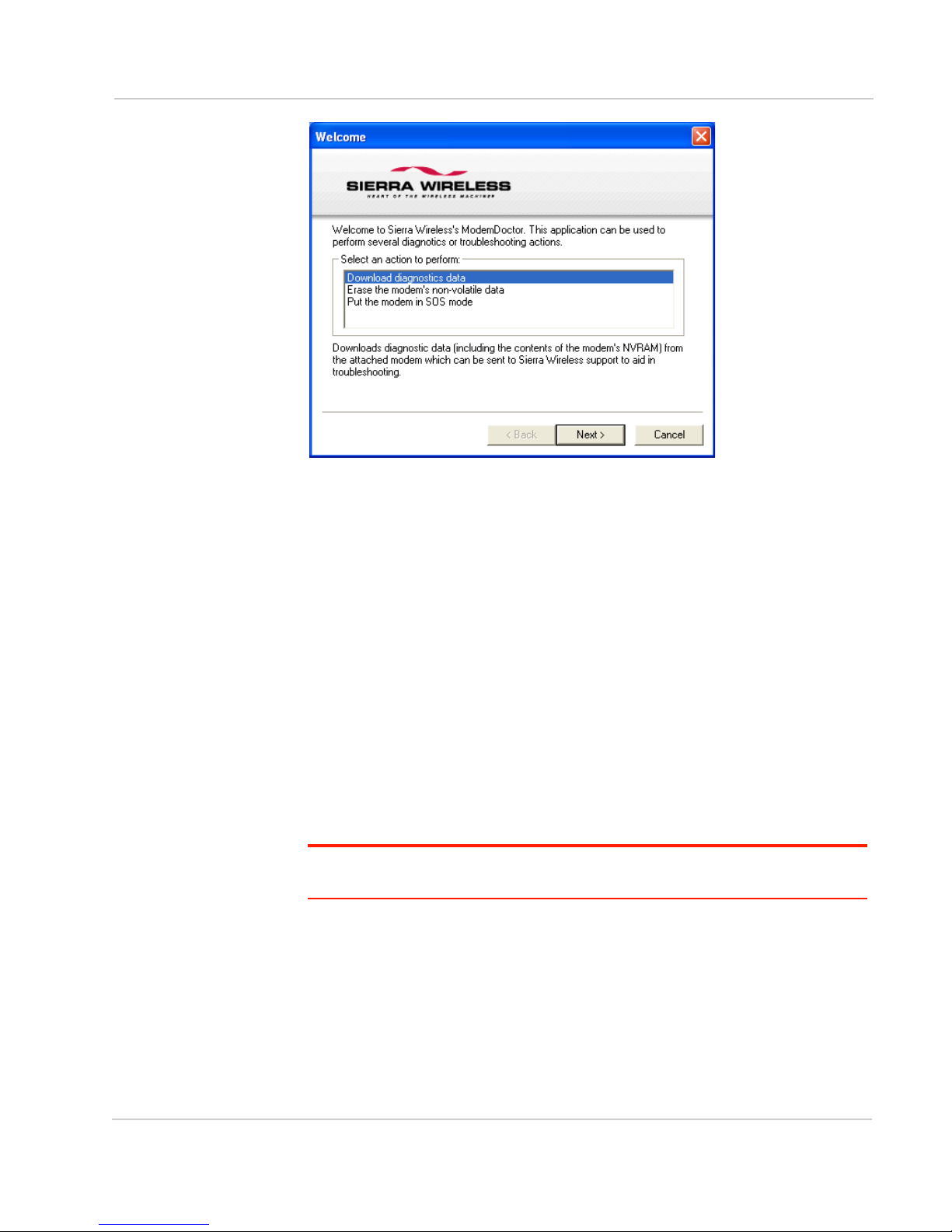
Figure 1-2: Modem Doctor
Introducing the MP Modem
Connection methods
You can connect the MP modem to a USB, Ethernet (RJ45), or serial (DB9) port
on a computer. When connected to a USB or Ethernet port, the MP modem
behaves like a network card. When connected to a serial port, the MP modem
behaves like a dial-up modem.
The MP modem also supports connections via IEEE802.11b/g if you are
implementing a WiFi version.
USB
The MP is equipped with a USB port which increases the methods by which you
can send and receive data from a connected computer. The USB port can be set
to work as either a virtual Ethernet port or a virtual serial port. A driver installation
is required to use the USB port in either mode.
Note: It is recommended that you use a USB 2.0 cable with your MP and connect directly
to your computer for best throughput.
Virtual serial port
The MP modem supports one virtual serial port over USB and one virtual serial
port over Ethernet. This VSP can be used, for example, to send AT commands, or
to run applications such as HyperTerminal
Rev 1.0 Mar.10 9
.
Page 16
AirLink MP User Guide
Special MP modem modes such as GPS that are supported on a serial port are
also available on the virtual port. For example, with the virtual port enabled, a
mapping application on your computer that normally listens for GPS messages on
a serial port listens for those same messages on the virtual port.
Networking
IPSec
IP protocol that drives the Internet is inherently insecure. Internet Protocol
Security (IPSec), which is a standards-based protocol, secures communications
of IP packets over public networks.
IPSec is a common network layer security control and is used to create a virtual
private network (VPN).
The advantages of the IPSec feature includes:
• Data Protection: Data Content Confidentiality allows users to protect their
data from any unauthorized view, because the data is encrypted (encryption
algorithms are used).
• Access Control: Access Control implies a security service that prevents
unauthorized use of a Security Gateway, a network behind a gateway or
bandwidth on that network.
• Data Origin Authentication: Data Origin Authentication verifies the actual
sender, thus eliminating the possibility of forging the actual sender’s identification by a third-party.
• Data Integrity: Data Integrity Authentication allows both ends of the communication channel to confirm that the original data sent has been received as
transmitted, without being tampered with in transit. This is achieved by using
authentication algorithms and their outputs.
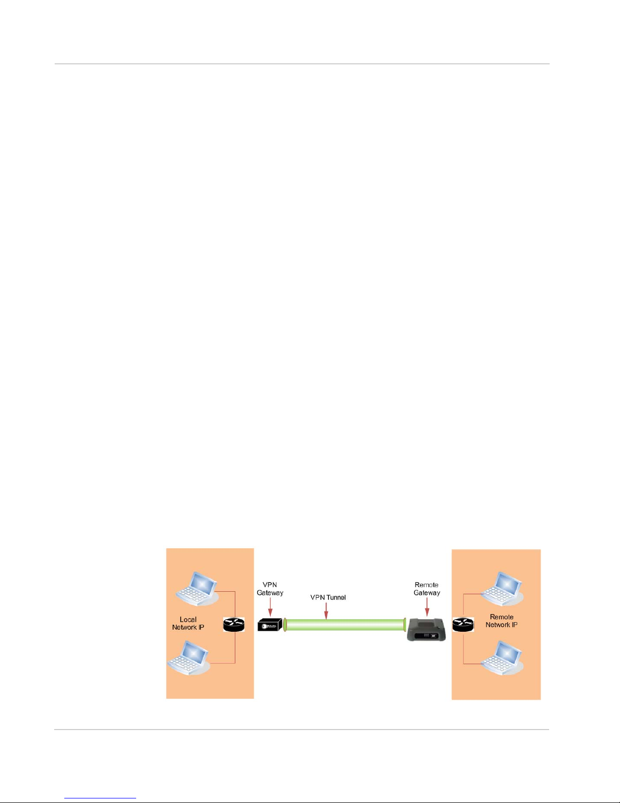
The IPSec architecture model includes the Sierra Wireless AirLink modem as a
remote gateway at one end communicating, through a VPN tunnel, with a VPN
gateway at the other end. The remote gateway is connected to a Remote network
and the VPN is connected to the Local network. The communication of data is
secure through the IPSec protocols.
Figure 1-3: IPSec Architecture
10 2130795
Page 17

Introducing the MP Modem
GREGRE
GRE (Generic Routing Encapsulation) tunnel is used to carry non-IP packets
through an IP Network. Non -IP packets, that are send over the GRE tunnel, need
to be first encapsulated. Hence, ALEOS is used to configure and encapsulate
non-IP packets and transmit over IP through the GRE tunnel.
Applications
Events Reporting
Events Reporting is Sierra Wireless AirLink’s modem’s new software feature
provided via ACEmanager and Ace View, that allows the users to generate
reports from the events that take place. Event Reporting Protocol is an intuitive
embedded protocol, which automatically formats the messages based on an
event trigger. The messages generated are then reported to the remote server.
GPS
The Global Positioning System (GPS) is a satellite navigation system used for
determining a location and providing a highly accurate time reference almost
anywhere on Earth. The US military refers to GPS as Navigation Signal Timing
and Ranging Global Positioning System (NAVSTAR GPS).
GPS consists of a “constellation” of at least 24 satellites in 6 orbital planes. Each
satellite circles the Earth twice every day at an altitude of 20,200 kilometers
(12,600 miles). Each satellite is equipped with an atomic clock and constantly
broadcasts the time, according to its own clock, along with administrative
information including the orbital elements of its motion, as determined by groundbased observatories.
A GPS receiver, such as the MP, requires signals from four or more satellites in
order to determine its own latitude, longitude, and elevation. Using time synced to
the satellite system, the receiver computes the distance to each satellite from the
difference between local time and the time the satellite signals were sent (this
distance is called psuedoorange). The locations of the satellites are decoded
from their radio signals and a database internal to the receiver. This process
yields the location of the receiver. Getting positioning information from fewer than
four satellites, using imprecise time, using satellites too closely positioned
together, or using satellites too close to the Earth’s curve will yield inaccurate
data.
The GPS data is then transmitted to a central location which uses a tracking
application to compile information about location, movement rates, and other
pertinent data.
Note: Depending on the location of the satellites in relation to the modem’s location and
how many signals are being received, the MP may encounter “GPS drift”. The MP may
report it is in a location a few feet from its actual location because it does not employ differential GPS.
Rev 1.0 Mar.10 11
Page 18

AirLink MP User Guide
Software
The MP modem comes with the following software:
• ACEview, the software for the MP modem which allows you to manage and
monitor your connections.
• The driver that forms the interface between the MP modem and your
Windows operating system.
• The firmware that is stored in non-volatile memory.
The MP modem has an embedded radio module, also made by Sierra Wireless, Inc. There are two firmware programs on the MP modem—one stored on
the controller board of the MP modem and one on the radio module.
The firmware was loaded into the radio module and controller board when the
MP modem was assembled. As new versions of the software and firmware
are released, they are posted at www.sierrawireless.com.
Documentation
This User Guide describes how to:
• Install the MP modem hardware.
• Connect the radio and GPS antennas.
• Connect a notebook computer and other input/output
(I/O) devices.
• Install the software.
• Interpret the LEDs on the MP modem and the indicators in the ACEview
software.
• Configure the MP modem to report GPS and/or I/O data (from sensors,
gauges, or panic buttons).
• Use the MP modem to connect to a network.
• Configure WAP.
This User Guide is provided as a PDF (Portable Document Format) file on the
installation CD.
The ACEview User Guide describes all the icons and indicators in ACEview and
provides detailed instructions on using ACEview to make data connections. When
using ACEview, you can access help through the menu system or by pressing the
<F1> key.
12 2130795
Page 19

Tools and Reference Documents
User Guide Description
Introducing the MP Modem
ALEOS User Guide This document discusses software configuration in ACEmanager and about
ACEview User Guide This document explains the use of this utility tools which is used to view and
ACEnet User Guide This document explains the use of ACEnet services for remote management
the explains different ALEOS features.
monitor the connection state of a Sierra Wireless AirLink device.
of Sierra Wireless AirLink device.
Rev 1.0 Mar.10 13
Page 20

AirLink MP User Guide
14 2130795
Page 21

2: Getting Started
•Plan your MP
modem
installation
• Required equipment
•System
requirements
This chapter provides:
• An overview of the installation process
• Information about the equipment you’ll need
• System requirements for the clients you want to use with the MP
modem
• Planning considerations
Overview of installation steps:
• Plan the installation.
· Location
· Connection type
· Routing
• Ensure required equipment is available.
• Ensure the clients have the necessary system requirements.
• Install the hardware (MP modem, clients, antennas, cables).
• Install the power harness or AC/DC adapter.
• Connect the MP modem to the computer (if using cables).
• Install the software (AceView and MP modem drivers).
• Configure your account.
• Configure networking options (if you are using the router
functionality).
• Configure the wireless access point settings (if desired).
2
Plan your MP modem installation
This section guides you through the decisions you need to make
before you begin the installation.
Where do you want to install your MP
modem?
The MP modem can be installed in a vehicle or in an office. The
same installation steps apply with the following exceptions:
• If you are installing the MP modem in a vehicle:
· Use the power harness to connect the MP modem to the
vehicle battery.
· Decide how to set the ignition sense option for powering the
MP modem on and off (that is, depending on the ignition switch
wiring, the MP modem can be turned on when the engine is
Rev 1.0 Mar.10 15
Page 22

AirLink MP User Guide
started, when the ignition is in accessory mode, or independently of the
ignition).
• If you are installing the MP modem in an office, an AC/DC adapter is
available.
Warning:
Warning:
40 0C.
Risk of electric shock: Only use the supply voltages listed in this user guide.
When using AC to DC adapter the ambient temperature should not exceed
What type of connection(s) do you plan to use?
The MP modem is capable of the following kinds of network connections:
• Serial
• USB
• Ethernet
• Wireless Access Point via IEEE 802.11b/g (MP WiFi modems only)
Data transfer rates vary, depending on the network, but note that the highest data
rate using a serial connection is 115.2 kbps.
Required equipment
Package contents
Each MP modem box contains:
• The MP modem
• A mounting template
• Mounting screws and washers
• An installation and documentation CD
• A power harness
If any of these are missing, please contact your account manager.
Available Accessories
To install the MP modem, you need the power harness, or an AC/DC adapter (for
office installations), mounting template, and the screws and washers that come
with the device.
You may also require:
• A USB, Ethernet, or 9-pin serial cable. This must be long enough to run
from the mounting location of the MP modem to the computer.
· The maximum length for the serial or USB cable is 5.5 m (18 feet). The
16 2130795
USB cable must have a Type A male connector at the computer end and a
Type B male connector at the MP modem end.
Page 23

Getting Started
· The Ethernet cable should have RJ-45 connectors. The MP modem’s
performance is affected by the type of Ethernet card in the computer and
the type of cable used. The minimum requirement for the Ethernet cable is
an unshielded twisted pair (UTP) cable, category 3 or 4. For better performance, use a shielded, category 5 cable. The maximum length is 100 m
(328 feet).
Note: If GPS is being
implemented, you require
either two antennas or a
combination Main RF and
GPS antenna.
• Main Radio frequency antenna and cable. The antenna must have the
appropriate regulatory approval, 50 ohm impedance, and a male TNC
connector. It may be a hard or magnetic-mount antenna.
• Access Point antenna and cable. MP.The WiFi antenna is an RP (reverse-
polarity) male SMA connector.
• Additional Diversity RF antenna (optional). This is required if you use the
receive diversity feature. The additional antenna must have a male SMA
connector.
• GPS antenna and cable (optional). This is necessary if you use the built-in
GPS module.
• Power supply. This is usually the vehicle’s battery.
• Appropriate electrical grounding. If a ground wire is necessary, use a
16-gauge wire and connect it to a ground screw.
• I/O cable (optional). This is required if a panic button, sensor, gauge, or
other I/O device is installed.
System requirements
Before you begin the installation, ensure your computer meets the following
system requirements necessary for the installation and running of ACEview
software:
Note: Do not connect the
MP modem to a USB port
on a computer before
installing the software.
• Operating systems:
· Windows
· Windows XP (Home or Professional)
• Available USB, Ethernet, or DB9 serial port
• CD-ROM drive (installation only)
• 32 MB RAM memory
Vista
MP modem accessories
For information about accessories for your MP modem— including cables and
antennas— contact your account manager or visit www.sierrawireless.com.
Rev 1.0 Mar.10 17
Page 24

AirLink MP User Guide
18 2130795
Page 25

3: Hardware and Software Installation
Main RF/GPS
antenna
MP modem
• Installation overview
• Install the MP
modem
This chapter provides instructions for installing the MP modem,
installing the ACEview software, and activating your account.
The MP modem installation should be done by a professional.
Before you begin the installation, ensure that you have all the
necessary components and equipment listed and have read the
“Installation overview” section below.
Installation overview
The MP modem may be installed in a vehicle (typically the trunk) and
connected to a laptop computer mounted on the dashboard (as
shown in the following illustration) or in an office.
3
Note: The MP modem is
designed for negativeground vehicles only. It will
not function in a positiveground vehicle.
Rev 1.0 Mar.10 19
Figure 3-1: Installation of the MP modem in a vehicle equipped with a notebook
computer and a combination antenna, using the car battery for power and ignitionsense wiring for power on/off.
MP modem housing
The MP modem has a rectangular metal housing. There is a
connector panel on the rear, an indicator panel on the front of the
housing, a reset button on top, and mounting holes along the bottom
edges on either side.
Page 26

AirLink MP User Guide
I/O connector (DB15HD)
Ethernet
GPS antenna (female SMA)
RS-232 serial (female DB9)
USB (Type B)
Main RF antenna (female TNC)
Power harness (Molex connector)
Diversity antenna (SMA)
Power
I/O
Ethernet Host
GPS
USB Host
Serial Host
Diversity
Main RF
WAP
WAP antenna for wireless
access (RP-SMA) for MP WiFi
SMA connector
only
Connector panel
The MP modem has the following connectors:
Figure 3-2: MP modem rear connectors
Note: Electrical installations are potentially
dangerous and should be
performed by personnel
thoroughly trained in safe
electrical wiring procedures for vehicles.
GPS and I/O options
The MP modem provides support for GPS (Global Positioning System) and for
attaching input/output devices.
GPS. If you plan to use the MP modem’s built-in GPS module, you must connect
a GPS antenna using an antenna cable, or use a combination antenna that can
connect to both the GPS and Main RF connectors on the MP modem housing.
Other I/O devices. Other devices, such as panic buttons, sensors, or gauges
may also be installed with the MP modem and connected with an I/O cable to the
I/O port. (See Do not connect the cables to the computer until you have installed
the software. on page 29.)
Overview of installation steps
The installation process for the MP modem varies depending on how you plan to
use it, where it best fits, and which of its features you plan to use. The main steps
are:
1. Mount the MP modem.
2. Mount the antennas and connect the cables.
· Main RF antenna and cable.
· Additional RF antenna and cable, if you plan to use receive diversity.
· GPS antenna and cable, if you plan to use GPS
· WAP antenna and cable (MP WiFi only)
3. Connect the power harness.
4. Connect the cable that runs between the MP modem and your computer to
the MP modem.
20 2130795
Page 27

Hardware and Software Installation
Do not connect the cable to the computer until you have installed the
software.
5. Install the software.
Note: Please refer to MP 597 Quick Start Guide for instructions on software installation
and MP modem activation.
6. Start ACEview and activate your account.
7. Test the system.
Install the MP modem
Step 1—Mount the MP modem
Note: Power off the MP
modem, your computer,
and any other devices
while you are connecting
cables.
If you are using the MP modem in a vehicle, it is usually mounted in the trunk, but
other possibilities are under the dashboard or a seat.
Select a location for the MP modem
When selecting a mounting location, remember the following:
• Do not expose the MP modem to weather and environmental conditions
beyond the ranges listed in the environmental specifications. Avoid excessive
heat from the engine compartment, heaters, or the exhaust system, and
extreme cold from direct contact with air conditioners or other cooling
systems. Never immerse it in any liquid.
• If you are replacing an MP modem, you can mount the new MP modem in the
same location using the existing mounting holes.
• Every device connected to the MP modem, as well as the MP modem itself,
should be grounded. (See Ground the MP modem on page 22 and Ground
the power harness on page 27.)
• Route cables to their destinations without using excess wiring.
• Make sure all connectors and the reset button are easy to reach and the
indicator lights are visible.
Mounting the MP modem
To mount the MP modem:
1. Use the provided mounting template to mark the location of the mounting
holes.
2. Drill 5/32" pilot holes (unless you are reusing holes from a previous MP
modem mounting).
Rev 1.0 Mar.10 21
Page 28

AirLink MP User Guide
3. Use the supplied mounting screws and washers to secure the MP modem
through the holes along the edge of the case bottom.
Figure 3-3: Mounting the MP modem. Arrows indicate the mounting holes.
Ground the MP modem
Note: Electrical installations are potentially dangerous and should be performed by
personnel thoroughly trained in safe electrical wiring procedures for vehicles.
Automotive installations usually provide a good quality ground for each piece of
electrical equipment. In most cases, ground the MP modem by connecting the
black ground wire of the power harness to either the vehicle chassis or to the
negative terminal of the battery.
If a device connected to the MP modem, such as a notebook computer, is not
properly grounded, it may ground itself through the cable connecting it to the MP
modem. This creates a hazard and could cause equipment damage. If you cannot
properly ground a device, a potential solution is to install a fuse in the ground
return wire.
The power harness has 5 A fuses on the red power wire and the white ignition
sense wire, but not on the black ground return wire. (See Step 3— Install the
power harness on page 25.)
22 2130795
Page 29

Hardware and Software Installation
If you are using a ground screw,
Power
I/O
insert it here.
You can also use a ground screw on the connector panel of the MP modem. Use
a 16-gauge wire if you choose to use a ground screw. A ground screw is not
required as long as the power harness is properly grounded.
Figure 3-4: The ground screw connector on the connector panel.
Note: Tighten cables
connected to the MP
modem by hand. Do not
use tools.
Step 2—Mount the antennas and install the
cables
The MP modem has two Main RF antenna connectors and one GPS antenna
connector. The MP WiFi has an additional RF antenna connector for an AP
antenna. The MP modem requires an RF antenna to connect to the wireless
network. The second RF connector is optional and allows for receive diversity.
The built-in GPS module requires a dedicated GPS antenna or a combination
antenna with cables to both the Main RF and GPS antenna connectors on the MP
modem.
If you already have an MP modem combination GPS antenna, you can re-use it
with your new MP modem. This antenna has two leads— one for Main RF (TNC
connector) and one for GPS (SMA connector).
Main RF antenna
Use an approved Main RF antenna to connect to the wireless network. The
antenna must have 50 ohms impedance and a cable with a TNC connector (or
SMA connector if the antenna is being used for receive diversity), as well as the
following characteristics:
• The total maximum gain, including cable loss, must not exceed 4.15 dBi (if
the antenna operates on the PCS band) or 5.1 dBi(if the antenna operates
only on the Cellular band).
• The antenna must transmit and receive on the necessary frequency bands in
your coverage area. The MP modem supports the following RF bands.
· CDMA Networks:
· 1900 MHz(PCS)
· 800 MHz(Cellular)
You can use a dual-band antenna that supports both frequencies.
Rev 1.0 Mar.10 23
If your MP modem will only be connected to networks that use one of the
bands, an appropriate single-band antenna is sufficient. Contact your service
provider for information about radio bands used in your area.
Page 30

AirLink MP User Guide
For more information about antennas for your installation contact your account
manager.
GPS antenna
The GPS antenna connects to the MP modem using a male SMA connector.
Contact your account manager for more information about compatible GPS
antennas.
MP WiFi only
The AP antenna must be installed by an RF professional. The AP antenna
connects to the MP modem using a reverse polarity male SMA connector.
Note: The WiFi antennas
approved for use with this
device must be of either a
PCB omni antenna with a
gain of no more than +2
dBi, or a dipole antenna
with a gain of no more than
+5dBi. No other antennas
are approved for use with
this device.
Antenna locations
When selecting locations for the Main RF, GPS, and AP antennas:
• Refer to the documentation provided with each antenna to determine whether
it requires a ground plane.
• Ensure that the Main RF antenna is mounted at least 20 cm (8 inches) from
vehicle occupants and bystanders.
• Ensure that all radio antennas (Main RF, GPS, CB radio, car radio) are
mounted at least 20 cm or more apart (30 cm recommended).
• If you are using receive diversity, connect an additional RF antenna to the
diversity antenna connector (SMA) on the back of the MP modem. Ensure
that the two RF antennas are 30 to 60 cm (12 to 24 inches) apart.
• (MP WiFi only) Ensure that the AP antenna is mounted at least 20 cm from
the Main RF antenna.
Install the antennas and cables
Note: When connecting the cables, hand-tighten the connectors; do not use tools.
To install the Main RF, GPS, and AP antennas:
1. Mount each antenna according to the instructions provided with it.
2. Thread the antenna cables to the MP modem. Secure the cables as
necessary.
Note: To avoid RF interference problems and
possible damage to the
MP modem, do not power
on the MP modem before
connecting the Main RF
antenna.
24 2130795
3. Connect the Main RF antenna cable to the TNC connector on the rear of the
MP modem.
4. If you are using receive diversity, connect the diversity RF antenna cable to
the diversity connector at the rear of the MP modem.
5. If you are using GPS, connect the GPS antenna cable to the GPS antenna
connector on the rear of the MP modem.
6. If you are using WAP, connect the AP antenna cable to the AP antenna
connector on the rear of the MP modem. (MPWiFi only)
Page 31

Hardware and Software Installation
GPS antenna
RF antenna
Diversity RF antenna
Serial Host
USB Host
GPS
Diversity
Main
RF
White wire
(Ignition sense)
Red wire
(Battery)
Unused
Black wire
(Ground)
Figure 3-5: The MP modem’s SMA connector for the GPS and AP antennas (top), and the TNC
connector for the Main RF antenna (bottom right).
The AP antenna must be installed by a professional and there must be a
separation of at least 20 cm. between the AP antenna and the main RF antenna.
Step 3—Install the power harness
Note: Connector part
numbers: 39-01-2040 or
39-01-2045. Pins part
number: 39-00-0039.
In a typical installation, the MP modem is connected to the vehicle’s battery with
the power harness. The MP modem supports a voltage range between 9 volts
direct current (VDC) and 36 VDC, and is designed for both 12 VDC and 24 VDC
vehicle electrical systems.
Note: Electrical installations are potentially dangerous and should be performed by
personnel thoroughly trained in safe electrical wiring procedures for vehicles.
Power connector
The power harness connects to the MP modem with a Molex connector.
Power connector (Molex) pinouts
The pinouts for the Molex connector on the power harness are:
Rev 1.0 Mar.10 25
Figure 3-6: Pinouts for the power harness.
Page 32

AirLink MP User Guide
Black unfused wire
(Ground)
White wire
(Ignition sense)
Red wire
(Battery)
MP modem
5 A fuses (on red
and white only)
Switch (vehicle
ignition key, or
separate)
Vehicle battery
The battery (red) and ignition sense (white) wires in the power harness include
5 A fuses. The black ground wire is not fused. (See Ground the power harness on
page 27.) Replacement power harnesses are available from Sierra Wireless.
Note: The battery cable used for a car, truck, or other mobile connection must be less than
3 meters in length.
Vehicle installation
This section applies to installing the MP modem in a vehicle. If you are installing it
in an office, see Office installation on page 28.
Ignition sense on/off wiring
This section only applies to installing an MP modem in a vehicle. If you are
installing the MP modem in an office building, use the AC/DC adapter.
Note: Do not install an on/
off switch on the main (red)
battery line, or connect the
white ignition sense wire to
the red battery wire. Both
configurations bypass the
MP modem's controlled
shutdown sequence, and
may cause data loss and
subsequent power-on
problems. Incorrect wiring
may also drain the vehicle
battery.
The MP modem’s power on/off is controlled by the ignition sense line (white wire)
using internal software, rather than a hard on/off switch on the red power line. The
red, black, and white wires connect to the battery and ignition switch as shown in
the power harness wiring diagram.
Note: The battery cable used for a car, truck, or other mobile connection must be less than
3 meters in length.
Figure 3-7: Wiring for the power harness.The white wire is the ignition sense.
• When the white ignition sense line is pulled high (5 to 36 V), the MP modem
powers on.
• When the ignition sense line is pulled low (less than 2 V), the MP modem
performs a controlled shutdown sequence (under software control), de-registering and saving any relevant operational data before powering off.
Ignition sense options
There are three ways to connect the ignition sense wiring:
26 2130795
Page 33

Hardware and Software Installation
• Engine on only. Connect the white ignition sense wire to the vehicle’s
ignition switch so that the MP modem is powered on only when the ignition
key is switched to the full “On” position, that is, when the engine has been
started. In this configuration, the engine must be running for the MP modem
to be on.
—or—
• Accessory on. Connect the white ignition sense wire to the vehicle’s ignition
switch so that the MP modem is powered on when the ignition is switched to
“Accessory” mode. In this configuration, the MP modem is on whenever other
vehicle electrical devices can be switched on—such as when the radio and
windshield fan can run.
—or—
Note: If you choose to
install a separate switch, it
must be connected to the
white ignition sense wire,
not the red battery wire, so
that the MP modem can
perform a controlled
shutdown, as described on
page 26.
• Separately switched. Connect the white ignition sense wire to a separate
switch mounted in a convenient location, which allows the MP modem to be
turned on or off regardless of the position of the ignition key. In this configuration, the MP modem can be powered on or off even if the key is not in the
ignition.
The MP modem also has a “Power Off Timer”. When power is removed from the
ignition sense wire, the MP modem remains on for the period defined by the
Power Off Timer, up to a maximum of 240 minutes. The Power Off Timer is
configured in ACEview. See the online help in ACEview for details.
Ground the power harness
You must connect the black ground wire from the power harness to the grounded
negative terminal of the vehicle battery, or another appropriate electrical ground.
Failing to ground the power harness properly may damage the MP modem, may
cause radio interference, and can be dangerous. (See Ground the MP modem on
page 22.) The ground wire in the MP modem power harness is not fused.
Power connections
Connecting the MP modem’s power wires properly is important—poor
connections can damage the wiring, the MP modem, or the vehicle’s electrical
system, and can be dangerous.
Note: Ensure that all wires
are correctly spliced or
crimped. Improper
grounding and wire
connections may lead to
equipment damage or
safety hazards.
Rev 1.0 Mar.10 27
Correct wire splicing
You can splice the wires of the power harness to the car wiring. Proper splicing is
essential to reliable operation of the MP modem. Do NOT use “quick taps”; they
reduce the integrity of the wire that is cut and let moisture into the cable.
An appropriate method of splicing is to strip a small portion of the insulation,
solder the wires together, then heat-shrink the connection to re-insulate it.
Page 34

AirLink MP User Guide
Crimp terminals
If suitable terminal connection points are available on the vehicle for power and
ignition sense, then using automotive crimp terminals is recommended. When
using crimp terminals, do not leave bare wire exposed. Do not use a crimp
terminal for more than one wire unless it is designed for that purpose.
Office installation
Use the AC/DC adapter available from Sierra Wireless to connect the power
harness to a standard outlet.
Step 4—Connect the MP modem to computer
cable
The MP modem connects to:
• A computer through a USB, Ethernet, or serial port
• Other optional devices through the DB15HD I/O connector
Note: 5.5-meter cable part
number: 6000083.
Note: Do not connect the MP modem to the computer until you have installed the
software.
The MP modem connects to a computer using:
• A USB cable (with a Type A connector on the computer end and a Type B
connector on the MP modem end). The maximum of the USB cable is 5.5 m
(18 feet). These cables are readily available from many suppliers.
• An Ethernet cable with RJ-45 connectors. The type of cable you use affects
the performance of the MP modem. The minimum requirement for the
Ethernet cable is an unshielded twisted pair (UTP) cable, category 3 or 4. For
better performance, use a shielded, category 5 cable. The theoretical
maximum length is 100 m (328 feet).
You can connect the MP modem Ethernet port directly to a computer or other
Ethernet device with either a cross-over or a straight-through cable.
• A serial cable (with a DB9 connector on the MP modem end). The maximum
length of the serial cable is 5.5 m (18 feet). Sierra Wireless sells suitable
serial cables in 5-meter (16-feet) lengths.
Serial connector (DB9) pinouts
The MP modem is configured as DCE (Data Communications Equipment) and
uses the standard RS232 pin designations: Pinouts for an RS232 male DB9 serial
cable (left) that connects to the MP modem’s female DB9 serial connector (right).
Note that the two figures’ pinouts are mirror images of each other, since they plug
together.
28 2130795
Page 35

Hardware and Software Installation
3. Received Data (RxD)*
2. Transmitted Data (TxD)*
4. Data Terminal Ready (DTR)
5. Signal Ground (GND)
6. Data Set Ready (DSR)
7. Clear To Send (CTS)
8. Request To Send (RTS)
9. Ring Indicator (RI)
DB9 MALE
* RxD and TxD are named with respect to the MP modem
(that is, RxD is the Receive Data input to the MP modem,
and TxD is the transmit data out of the MP modem)
DB9 female connector
1. Data Carrier Detect (DCD)
1
5
6
9
Serial Host
Diversity
RF
USB Host
Space logic 0
Transmission
region
Mark logic 1
Space logic 0
Transmission
region
Mark logic 1
˝
RS-232-C
Driver
RS-232-C
Receiver
+15 V
+5 V
-5 V
-15 V
+15 V
+3 V
-3 V
-15 V
2 V
noise margin
Figure 3-8: Pinout for MP DB9 connector
The serial connector uses these voltage specifications:
Figure 3-9: Voltage specifications for the MP modem’s serial connector.
Install the USB, Ethernet or serial cable
Note: Ensure that the MP
modem and your computer
are powered off while
installing cables.
Rev 1.0 Mar.10 29
To install the USB, Ethernet, or serial cable, thread the cable through the vehicle
and attach it to the USB, Ethernet, or serial connector on the MP modem.
Note: Do not connect the cables to the computer until you have installed the software.
GPS configuration and reporting
GPS receivers use an array of orbiting satellites operated by the United States
Department of Defense to triangulate their coordinates on the Earth’s surface. In
order to use the GPS module in the MP modem, a GPS antenna must be
connected to the MP modem. (The installation requires either two antennas—one
Main RF and one GPS—or a single combination RF/GPS antenna.)
For more information about GPS, see the Primer on GPS Operations (document
#2130313) on the Sierra Wireless web site, www.sierrawireless.com.
Page 36

AirLink MP User Guide
GPS protocols and commands
Note: The “MP 3G
Modems TAIP Reference
manual” (document
#2130312) provides a
description of the TAIP
commands that can be
used with the MP modem.
This is available at
www.sierrawireless.com
.
Information about Trimble
GPS modules, including
more documentation on
TAIP commands, is
available at
www.trimble.com
More information on
NMEA message standards
is available at
www.nmea.org
.
.
The GPS module supports two methods of reporting navigational information,
using either the TAIP (Trimble ASCII Interface Protocol) or NMEA (National
Marine Electronics Association) protocols. The GPS module is pre-configured for
TAIP. If you are using a GPS application that requires data to be reported
according to the NMEA protocol, the MP modem must be reconfigured using an
AT command. (See the MP 3G Modems AT Command Reference manual
(document #2130810.)
NMEA is a reporting protocol only, while TAIP provides the ability to send
commands to the module to query for information and configure reports. When
the MP modem is set for TAIP, commands can be sent to the MP modem in these
ways:
• Using ACEview
• Using AT commands
TAIP commands can be used to:
• Query the MP modem for its current position, heading, and speed
• Enable and disable automatic reporting of GPS data, and set the interval at
which automatic reports are sent
• Configure the format of reports
GPS display in ACEview
To view ACEview’s GPS Display window, which reports latitude, longitude, speed,
direction, altitude, and local and UTC time
click the GPS icon on the main ACEview window.
1
, select Tools > Display GPS or double-
From a cold start (where the MP modem is powered on with no stored
navigational data), it may take up to 39 seconds for the GPS module to obtain
satellite fixes and begin reporting.
GPS TAIP quick reference
The following table is a quick summary of the TAIP message identifiers. For
detailed information and message syntax, see the MP 3G Modems TAIP
Reference manual (document #2130312) and the GPS documentation on TAIP
commands available at www.trimble.com.
TAIP Message Identifiers
AL Altitude/Vertical Velocity
CP Compact Position Solution
ID Identification Number
1. UTCreplacesGreenwichMeanTimeasthebasisforstandardtime
throughouttheworld.UTC,whichusesatomicmeasurementsratherthan
theEarth’srotation,istheequivalentofmeansolartimeattheprimemerid‐
ian(0°longitude).
30 2130795
Page 37

Hardware and Software Installation
TAIP Message Identifiers
IP Initial Position
LN Long Navigation Message
PV Position/Velocity Solution
RM Reporting Mode
RT Reset
ST Status
TM Time / Date
VR Version Number
I/O device installation and configuration
The I/O port on the MP modem allows for remote monitoring of gauges, sensors,
and alarms. You can use this feature to display readings from instruments or
gauges and to remotely monitor panic buttons or alarms.
The MP modem’s I/O port is a standard female DB15HD connector for remote
monitoring of gauges, sensors, and alarms. If you are planning to use these
devices, you need to create a custom I/O cable.
This section describes how to connect and configure these I/O devices to work
with the MP modem.
Connecting these devices requires that you make a customized I/O cable. The
cable must have, at one end, whatever connector is required by the I/O device,
and at the other end, the High Density DB15 connector. The cable wires must pin
to the appropriate pin numbers on the I/O connector. The pinouts are described in
the next section.
The maximum length of the I/O cable is 15 feet.
Before using the digital input/output lines, you must configure them as inputs or
outputs.
Connector pinouts
The MP modem’s I/O port is a female DB15HD connector with eight active I/O
pins:
• Two (2) digital I/O pins.
• Two (2) digital input pins.
• Four (4) analog input pins.
There are also six reserved pins and one ground pin.
Rev 1.0 Mar.10 31
Page 38

AirLink MP User Guide
2.
Reserved—do not connect
3. Digital Input/Output 1
4. Digital Input 3
5.
Reserved—do not connect
6.
Reserved—do not connect
7. Analog Input 2
8. Analog Input 4
9.
Reserved—do not connect
10. Ground (GND)
11. Digital Input/Output 2
12. Digital Input 4
13.
Reserved—do not connect
14. Analog Input 1
15. Analog Input 3
1.
Reserved—do not connect
1
6
5
11
10
15
DB15HD female connector
DB15HD male cable
on rear of MP modem
Figure 3-10: Pinouts for a male DB15HD I/O cable (left) that connects to the MP modem’s female
DB15HD I/O connector (right). Note that the two figures’ pinouts are mirror images of each other,
since they plug into one another.
Port specifications
Note: No more than
36 VDC should be applied
to any I/O pins.
See I/O port characteristics on page 75 for the technical specifications of the I/O
ports, including input voltages.
Digital input devices
Digital input devices are those that have only two states and send a signal to the
MP modem in one of those states. An example of a digital input device might be a
gun rack alarm that sends a signal to the MP modem any time the gun rack is
open. Another example would be a panic button that sends a signal to the MP
modem when it is pushed.
A digital input can be connected to four of the pins on the DB15HD connector:
Pins 3, 4, 11, and 12. (Pins 3 and 11 could alternatively be used for digital
output.)
Note: Before using the input/output lines, you must configure them as inputs or outputs.
32 2130795
Page 39

Hardware and Software Installation
Typically a digital input device should be connected between Ground (Pin 10) and
the input port (Pin 3, 4, 11, or 12).
Figure 3-11: A button wired to Pin 4 (digital input) and Pin 10 (Ground).
The pins report a logic high on an input of 3.45 VDC. An internal pull-up resistor
provides a high condition when the switch is open.
The digital input pins report a logic low on an input between 0 VDC and 0.8 VDC.
Sinking the input pin to ground yields a logic low (0x00) when the port is polled.
If you configure the MP modem to send data to a network server, digital input
data can be remotely monitored.
Example: panic button connections
An I/O cable for a panic button requires a wire to one of the digital input or I/O
pins (such as #3) and one wire to the Ground pin (#10).
Digital output devices
Digital output devices are those that have only two states and the state is
controlled by a signal from the MP modem. Any device that is to be switched on
and off from ACEview would be installed as a digital output device.
A digital output can be connected to two of the pins on the DB15HD connector:
Pins 3 and 11. (These can be used for either input or output.)
Note: Before using the input/output lines, you must configure them as inputs or outputs.
Typically a digital output device should be connected between Ground (pin 10)
and the output port (Pin 3 or 11).
Rev 1.0 Mar.10 33
Page 40

AirLink MP User Guide
Figure 3-12: Wiring for using Pin 3 (digital output) as an electronic switch. Pin 10 is Ground.
The digital I/O ports provide open-collector output to a maximum of 500 mA.
Analog input devices
Analog input devices are those that generate a signal of varying voltage, based
on the state of an instrument or gauge. An example of an analog input device
might be a sensor that detects the vehicle’s speed.
An analog input can be connected to four of the pins on the DB15HD connector:
Pins 7, 8, 14, and 15.
Typically an analog input device should be connected between Ground (pin 10)
and the input port (Pin 7, 8, 14, or 15).
Figure 3-13: A sensor wired to Pin 7 (analog input) and Pin 10 (Ground).
The analog input ports use a 10-bit (1024-step) analog-to-digital converter over a
range from 0 to 3.45 VDC, yielding a digital step resolution of 0.0032 V.
Example: analog sensor connections
An I/O cable for an analog sensor requires a wire to one of the analog input pins
(such as #7) and one wire to the Ground pin (#10).
34 2130795
Page 41

Hardware and Software Installation
Step 5- Start ACEmanager
ACEmanager is a free utility. Follow the steps below to connect to ACEmanager.
• Ensure MP connectivity to access ACEmanager.
• Go to: http://192.168.13.31:9191 the first time you connect to ACEmanager.
• Enter username as User and password as 12345.
• By default ethernet uses public mode and all other interfaces are in private
mode using different subnets to differentiate the connection types.
The default private for Ethernet is also in a different subnet from the other
connection types.
Table 3-1: Factory Defaults
Interface MP Connected Device
Ethernet Private default 192.168.13.31* 192.168.15.100
USB/NET 192.168.14.31 192.168.14.100
DUN 192.168.15.31 192.168.15.100
WiFi* 192.168.17.31 192.168.17.100
*can be changed via ACEmanager
Rev 1.0 Mar.10 35
Page 42

AirLink MP User Guide
36 2130795
Page 43

4: MP Modem Operation
• Status indicators
• ACEview software
Operating the MP modem requires some knowledge of both the MP
modem hardware and the ACEview software. This chapter describes
the basics of each.
Turning the MP modem on and off
If the MP modem is installed in a vehicle, the way in which the MP
modem is wired determines how it is powered on and off. In most
cases the power supply for the MP modem is the vehicle's electrical
system and the MP modem is powered on and off in one of these
ways:
• Engine on. The MP modem is powered only when the ignition is
on. (The MP modem is only on when the engine is on.)
—or—
• Accessory on. The MP modem is powered when the ignition is
switched to "Accessories". (This allows the MP modem to be
powered when the engine is off.)
—or—
• Separately switched. The MP modem is connected to a
separate on/off switch so that it can be turned on and off
independently of the engine and vehicle accessories.
4
Rather than cutting power to the MP modem, the ignition key or
power switch allows the MP modem to perform a controlled shutdown
sequence that avoids data loss. (You can also set the MP modem to
wait up to 240 minutes after the power switch has been turned off
before it shuts down.)
Rev 1.0 Mar.10 37
Page 44

AirLink MP User Guide
Power indicator
Receive (Rx)
indicator
Transmit (Tx)
GPS indicator
indicator
Status indicators
The MP modem’s indicator panel includes four indicator lights.:
Figure 4-1: The indica tor panel of the MP modem.
The following table shows the behavior of the LEDs during normal MP modem
operation:
Table 4-1: LED operation
LED Behavior Indicates
Power Off MP modem is not powered.
Tx Flashing MP modem is transmitting data.
Rx Flashing MP modem is receiving data.
GPS Off GPS module is not active.
On solid MP modem has established a network connection.
Solid GPS module is active and providing valid fixes.
Reset the MP modem
The reset button for the MP modem is on the top of the housing.
To reset the MP modem, press the button until all four
indicator lights illuminate. (Do not use sharp implements
that might puncture the rubber.)
Resetting the MP modem is equivalent to turning the
MP modem off and on. This terminates any data
connection and causes the MP modem to perform a
restart. (Stored settings are not lost.)
Figure 4-2: The MP modem reset button.
38 2130795
Page 45

MP Modem Operation
ACEview software
ACEview is the program used to manage and monitor the MP modem. For
information about installing ACEview, see the AceView User Guide.
ACEview allows you to:
Note: Depending on the
operating mode, it may not
be necessary to run
ACEview to use the MP
modem, but it does provide
useful status information.
• Determine signal strength, roaming status, and other network connection
parameters.
• Monitor the status of the MP modem and network services.
• View GPS information.
Launching ACEview
To launch ACEview, start ACEview by choosing Start > Programs >
Sierra Wireless Inc > ACEview > ACEview
Please refer to the AceView User Guide Rev A.
, or double click the desktop shortcut.
Rev 1.0 Mar.10 39
Page 46

AirLink MP User Guide
40 2130795
Page 47

5: Configuring the MP modem
• ACEmanager
• Using a Terminal
Application with
AT Commands
• AT Command
With ALEOS as its “brain”, the MP is a highly configurable device.
To configure your MP, you have two options. You can use the
configuration and management applications of the AceWare suite or
you can use a terminal emulator application such as HyperTerminal,
PuTTY, or many others.
ACEmanager
To get a more expanded view of the other ACEmanager features,
refer to the ACEmanager Guide.
A full listing of all the configuration commands for you modem are in
Appendix A.
Using a Terminal Application with
AT Commands
5
You can access and configure your MP using a terminal application
such as Microsoft HyperTerminal, PuTTY, or similar. The following
directions are for HyperTerminal which is part of a standard
installation of Windows XP.
Start > All Programs > Accessories > Communications >
HyperTerminal
Rev 1.0 Mar.10 41
Page 48

AirLink MP User Guide
Figure 5-1: HyperTerminal
1. Choose a name and icon for your connection
a. Choose a name for your connection, such as MP or Sierra Wireless
AirLink Solutions. The name and icon are only for your own reference so
you can find the connection at a later date.
Tip:
If you want to have a connection saved for both local and remote, it is recommended
the connection name reflect the connection type, i.e. MP local.
b. Select OK.
2. Connect to
Using USB/Serial:
a. Select COM1, or the comport to which the modem is connected, for the
“Connect Using”.
42 2130795
Page 49

Figure 5-2: Connect To
b. Change or verify the settings:
· Bits per Second: 115200 (default)
· Data Bits: 8
· Parity: None
· Stop Bits: 1
· Flow Control: Hardware.
Configuring the MP modem
Figure 5-3: Port Settings
Tip:
If you have configured the MP for settings different than the defaults for Bits per
Second, Data Bits, Parity, and/or Stop Bits, you will need to use your changed settings.
c. Select OK.
Using Ethernet:
d. Typ e in 192.169.14.31 for Host Address.
Tip:
The Host IP address can be a default or one set up by the user.
e. Change the “Port Number” to 2332.
Rev 1.0 Mar.10 43
Page 50

AirLink MP User Guide
192.168.14.31
f. Select OK.
3. Connected
Connecting on USB/net will prompt for password.
Figure 5-4: HyperTerminal : TCP/IP connected
44 2130795
Page 51

Configuring the MP modem
Figure 5-5: HyperTerminal : connected
a. If you are prompted for a password, enter 12345 (default password).
Tip:
You will not be prompted for a password if you connect using a COM port.
b. Ty pe AT and press Enter. You should get a reply of “OK” or “0”.
c. To see what you are typing as you type it, you will need to turn on the
echo and verbose mode. Type AT E 1 V1 and press Enter.
d. If you get a reply of “OK”, then you entered the command successfully. If
you get a reply of “0” or “ERROR”, try entering the command again.
AT Command
When using a terminal application, you will need to manually type in each
command.
• For most commands, when you are entering them using a terminal
connection, you will need to preface the command with AT (exceptions are
noted), i.e. ATA which is listed as A.
• Some commands have specific parameters while other commands will take
whatever you type.
• Required variable parameters are denoted with italicized text, example, Dn.
The n is variable.
• Acceptable parameters and/or specific formats are listed with each
command.
• Most commands with parameters can be entered with ? to read the current
value (for example, AT& D ? will respond with “2” if the default has not been
changed).
• Optional parameters are denoted with square brackets [ ].
Rev 1.0 Mar.10 45
Page 52

AirLink MP User Guide
• AT Commands are not case sensitive. A capital “E” is the same as a lowercase “e”.
• When you are using a terminal connection, if you enter a command which is
recognized by the MP, it will respond with “OK”. If the command is not recognized, the response will be “ERROR”.
• Those commands applicable only to certain model numbers of the MP will be
noted.
Caution:
and must be included. Commands with symbols other than * may require PassThru mode.
Symbols listed with commands, such as *, /, &, or ?, are part of the command
46 2130795
Page 53

A: Support and Warranty
Technical support
To obtain technical support for your MP modem, and firmware and
software upgrades, please contact your account manager.
Online technical support resources are also available at
www.sierrawireless.com.
Warranty
Sierra Wireless, Inc. warrants the MP modem against all defects in
materials and workmanship for a period of three (3) years from the
date of purchase.
The sole responsibility of Sierra Wireless, Inc. under this warranty is
limited to either repair or, at the option of Sierra Wireless, Inc.,
replacement of the MP modem. There are no expressed or implied
warranties, including those of fitness for a particular purpose or
merchantability, which extend beyond the face hereof.
Sierra Wireless, Inc. is not liable for any incidental or consequential
damages arising from the use, misuse, or installation of the MP
modem.
This warranty does not apply if the serial number label has been
removed, or if the MP modem has been subjected to physical abuse,
improper installation, or unauthorized modification.
Rev 1.0 Mar.10 47
Page 54

AirLink MP User Guide
48 2130795
Page 55

B: Technical Specifications
This chapter provides technical data for the MP modem.
Note: The technical specifications are subject to change without notice.
Regulatory, radio frequency and
electrical specifications
Approvals FCC
Industry Canada
EU RoHS
Network compliance CDMA 1xEV-DO Revision A (IS-856-A)
CDMA 1xEV-DO Revision 0 (IS-856)
CDMA 1X (IS-2000)
CDMA IS-95A
Voltage range 9–36 VDC
Reverse polarity
protection
Current draw Max transmit (23 dBm output)
Maximum output
power
Transmit PCS: 1850 to 1910 MHz
Receive PCS: 1930 to 1990 MHz
a. This applies to a typical installation with a well-matched antenna.
All current values are measured with an input voltage of 12 V.
Compliant
a
Cellular: 375 mA
PCS: 395 mA
Typical transmit: 250 mA average
Receive: 215 mA
Idle (Ignition Sense off): 2 mA
23 dBm (200 mW)
Cellular:
Cellular: 869 to 894 MHz
824 to 849 MHz
Rev 1.0 Mar.10 49
Page 56

AirLink MP User Guide
Environmental specifications
Operating
temperature
Storage
temperature
Humidity 95% RH non-condensing
Drop MIL 810F, Section 516.5 D
Shock MIL 810F, Method 516.5 Annex C (Fragility)
Vibration MIL 810F, Method 514.5, Cat 5, Section 2.2.2
ESD Operational ± 6 kV contact, as per
EU RoHS Compliant
MIL 810F, Method 501.4, 502.4
-30°C to +70°C
(-22°F to +158°F)
MIL 810F, Method 501.4, 502.4
-40°C to +85°C
(-40°F to +185°F)
MIL 810F, Section 507.4
Procedure II (Loose Cargo)
ASTM D-4169 (Restrained Cargo)
MIL 810F, Method 514.5, Cat 4, Section 2.2.1,
Procedure I, Figure 514.5 C-1 (Transport
operation)
IEC 61000-4-2
50 2130795
Page 57

Weight and dimensions
Weight 0.9 kg (2 lbs)
Height 49 mm (1.93 in)
Width 138 mm (5.43 in)
Length 176 mm (6.93 in)
Case material Metal
Case surface Scratch-resistant powder coat paint
Host interfaces
Serial One — DB9 female
USB One — USB Type B, USB 1.1/2.0 compliant
Ethernet One — RJ45 female
Weight and dimensions
Other interfaces
Input / output One — High-density DB15 female
Network antenna One — TNC female
Receive diversity antenna One — SMA female
GPS antenna One — SMA female
Reset One — Manual reset button
Power One — Molex 39-01-0029 female
AP antenna One — SMA reverse-polarity female
Rev 1.0 Mar.10 51
Page 58

AirLink MP User Guide
GPS specifications
Satellite channels 12 channel, continuous tracking
Protocols TSIP, TAIP, NMEA 0183 V3.0
Acquisition times Re-acquisition: 2 sec.
Hot start: 9 sec.
Warm start: 35 sec.
Cold start: 39 sec.
Accuracy Horizontal: < 3 m (50%), < 8 m (90%)
Altitude: < 10 m (50%), < 16 m (90%)
Velocity: 0.06 m/sec
Sensitivity Tracking: –152 dBm
Acquisition: –142 dBm
Operational limits Velocity: 515 m/sec.
I/O port characteristics
Absolute maximum voltage -0.3 VDC to 36 VDC
Digital I/O count Total: 4; two dedicated inputs, two
configurable input/outputs
Digital outputs Open collector
Digital inputs Open collector, max current 500 mA
Note: Do not apply voltage, connect
switch between pin and ground.
Vih, min 2 VDC
Vil, max 0.8 VDC
Vih, max 36 VDC
Analog input count Total: 4
Analog input Zero-scale: 0 V DC
Full-scale: 3.3 VDC
Leakage current: 66 µA
ACEview software
Operating systems Microsoft Windows Vista, 2000, and XP
Languages
User interface English, French, German, Spanish, Italian,
Online help English and French
52 2130795
Japanese, and Simplified Chinese
Page 59

Wireless access point specifications
Wireless access point specifications
Standards IEEE 802.11b, IEEE 802.11g, IEEE 802.11i
Channels 1 (2.412 GHz) to 11 (2.462 GHz)
Band 2.4 GHz Wireless-G
Channels spacing 5MHz
Security features Open
Encryption Wireless Equivalent Privacy (WEP)
WPA (Wireless Protected Access)
WPA2
Open WEP (64-bit and 128-bit)
Shared WEP (64-bit and 128-bit)
Temporal Key Integrity Protocol (TKIP)
Advanced Encryption Standard (AES)
Rev 1.0 Mar.10 53
Page 60

AirLink MP User Guide
54 2130795
Page 61

C: Regulatory Information
• Canada
• U.S.A.
• Important Note
• FCC Caution
• Approved antennas
Canada
Note:Unauthorized
modifications or changes
not expressly approved by
Sierra Wireless, Inc. could
void compliance with
regulatory rules, and
thereby your authority to
use this equipment.
To ensure that the MP modem meets Health Canada’s Safety Code 6
requirements, a separation distance of at least 20 cm (8 inches) must
be maintained between the modem’s Main RF antenna and the body
of the user and any nearby persons at all times and in all applications
and uses.
Additionally, the maximum antenna gain in the PCS band, including
cable loss, must not exceed 4.15 dBi, and in the Cellular band, must
not exceed 5.1 dBi, to comply with Industry Canada and Health
Canada regulations limiting both maximum RF output power and
human exposure to RF radiation.
For the MP modem, the maximum gain for the AP antenna must not
exceed 3 dBi, and the AP antenna must be at least 20 cm away from
the Main RF antenna.
Antenna Considerations
Although the antenna model(s) used with these devices meet(s) the
Industry Canada Radio Frequency requirements, it is possible that
the future customers may swap them for different ones without
network provider's knowledge and approval. Such customers must be
made aware of, and follow, the Radio Frequency requirements
applied in this Technical Approval:
• RSS-102 "Radio Frequency Exposure Compliance of Radiocommunication Apparatus (All Frequency Bands)"
• RSS-129 "800 Mhz Dual-Mode CDMA Cellular Telephones"
• RSS-132e "Cellular Telephones Employing New Technologies
Operating in the Bands 824-849 Mhz and 869-894 Mhz"
• RSS-133 r1 "2 GHz Personal Communications Services"
Rev 1.0 Mar.10 55
U.S.A.
To comply with FCC regulations limiting both maximum RF output
power and human exposure to RF radiation, the maximum antenna
gain, including cable loss, in the PCS band, must not exceed 4.15 dBi
or and in the Cellular band, must not exceed 5.1 dBi or .
Page 62

AirLink MP User Guide
The Main RF Main RF antenna must be mounted such that there is a separation
distance of at least 20 cm (8 inches) between the Main RF antenna and the body
of the user or any nearby persons.
For the MP modem, the maximum gain for the AP antenna must not exceed 3
dBi, and the AP antenna must be professionally installed with a separation
distance of at least 20 cm away from the Main RF antenna, per FCC Part 15
requirements.
Note: This equipment has been tested and found to comply with the limits for a Class A
digital device, pursuant to Part 15 of the FCC Rules. These limits are designed to provide
reasonable protection against harmful interference when the equipment is operated in a
commercial environment. This equipment generates, uses, and can radiate radio
frequency energy and, if not installed and used in accordance with the instruction manual,
may cause harmful interference to radio communications. Operation of this equipment in a
residential area is likely to cause harmful interference in which case the user will be
required to correct the interference at his own expense.
Important Note
To comply with FCC RF exposure compliance requirements, the antenna used for
the WiFi transmitter must be installed to provide a separation distance of at least
20 cm from all persons and must not be co-located or operating in conjunction
with any other antenna or transmitter.”
FCC Caution
Any changes or modifications not expressly approved by the party responsible for
compliance could void the user's authority to operate this equipment.
Approved antennas
The WiFi antennas approved for use with this device must be of either a PCB
omni antenna with a gain of no more than +2 dBi, or a dipole antenna with a gain
of no more than +5dBi. No other antennas are approved for use with this device.”
56 2130795
Page 63

 Loading...