

Page 1
AirLink MG90
Hardware User Guide
4118699
Rev 3
Page 2

Preface
Important
Notice
Safety and
Hazards
Due to the nature of wireless communications, transmission and reception of data can
never be guaranteed. Data may be delayed, corrupted (i.e., have errors) or be totally
lost. Although significant delays or losses of data are rare when wireless devices such
as the Sierra Wireless modem are used in a normal manner with a well-constructed
network, the Sierra Wireless modem should not be used in situations where failure to
transmit or receive data could result in damage of any kind to the user or any other
party, including but not limited to personal injury, death, or loss of property. Sierra
Wireless accepts no responsibility for damages of any kind resulting from delays or
errors in data transmitted or received using the Sierra Wireless modem, or for failure
of the Sierra Wireless modem to transmit or receive such data.
Do not operate the Sierra Wireless modem in areas where blasting is in progress,
where explosive atmospheres may be present, near medical equipment, near life
support equipment, or any equipment which may be susceptible to any form of radio
interference. In such areas, the Sierra Wireless modem MUST BE POWERED OFF.
The Sierra Wireless modem can transmit signals that could interfere with this
equipment.
Do not operate the Sierra Wireless modem in any aircraft, whether the aircraft is on
the ground or in flight. In aircraft, the Sierra Wireless modem MUST BE POWERED
OFF. When operating, the Sierra Wireless modem can transmit signals that could
interfere with various onboard systems.
Note: Some airlines may permit the use of cellular phones while the aircraft is on the ground
and the door is open. Sierra Wireless modems may be used at this time.
Limitation of
Liability
The driver or operator of any vehicle should not operate the Sierra Wireless modem
while in control of a vehicle. Doing so will detract from the driver or operator's control
and operation of that vehicle. In some states and provinces, operating such
communications devices while in control of a vehicle is an offence.
The information in this manual is subject to change without notice and does not
represent a commitment on the part of Sierra Wireless. SIERRA WIRELESS AND ITS
AFFILIATES SPECIFICALLY DISCLAIM LIABILITY FOR ANY AND ALL DIRECT,
INDIRECT, SPECIAL, GENERAL, INCIDENTAL, CONSEQUENTIAL, PUNITIVE OR
EXEMPLARY DAMAGES INCLUDING, BUT NOT LIMITED TO, LOSS OF PROFITS
OR REVENUE OR ANTICIPATED PROFITS OR REVENUE ARISING OUT OF THE
USE OR INABILITY TO USE ANY SIERRA WIRELESS PRODUCT, EVEN IF
SIERRA WIRELESS AND/OR ITS AFFILIATES HAS BEEN ADVISED OF THE
POSSIBILITY OF SUCH DAMAGES OR THEY ARE FORESEEABLE OR FOR
CLAIMS BY ANY THIRD PARTY.
Notwithstanding the foregoing, in no event shall Sierra Wireless and/or its affiliates
aggregate liability arising under or in connection with the Sierra Wireless product,
regardless of the number of events, occurrences, or claims giving rise to liability, be in
excess of the price paid by the purchaser for the Sierra Wireless product.
Rev 3 Feb.17 2 4118699
Page 3
AirLink MG90 Hardware User Guide
Patents This product may contain technology developed by or for Sierra Wireless Inc. This
product includes technology licensed from QUALCOMM
manufactured or sold by Sierra Wireless Inc. or its affiliates under one or more
patents licensed from InterDigital Group and MMP Portfolio Licensing.
®
. This product is
Copyright © 2017 Sierra Wireless. All rights reserved.
Trademarks Sierra Wireless
registered trademarks of Sierra Wireless.
Windows
Macintosh
U.S. and other countries.
QUALCOMM
license.
Other trademarks are the property of their respective owners.
®
, AirPrime®, AirLink®, AirVantage® and the Sierra Wireless logo are
®
and Windows Vista® are registered trademarks of Microsoft Corporation.
®
and Mac OS X® are registered trademarks of Apple Inc., registered in the
®
is a registered trademark of QUALCOMM Incorporated. Used under
Contact
Information
Sales information and technical
support, including warranty and returns
Web: sierrawireless.com/company/contact-us/
Global toll-free number: 1-877-687-7795
6:00 am to 6:00 pm PST
Corporate and product information Web: sierrawireless.com
Revision
History
Revision
number
1 May 2016 Document created (Trial release)
2 October 2016 General release
Release date Changes
Changed recommended fuse to 9A (from 7.5A)
Updated factory reset instructions
Updated power consumption values
Updated LED behavior descriptions (Power, Signal, ALL LEDs)
Added Bracket Mount details
Added I/O Configuration topic (GPIOs)
Updated MTBF
Added SMA wrench details
Organized radio frequency/Tx power consumption tables by SKUs
Updated Battery Replacement/Disposal topic
Added topic to boot from USB for software update
Rev 3 Feb.17 3 4118699
Page 4
Preface
Revision
number
3 February 2017 Updated Table 3-1, General Router Specifications, on page 30:
Release date Changes
• Added ACMA RCM certification
• Added Conducted Electrical Transients
Corrected RS-232 pin directions in Table 3-2, Serial Connector Pin-out, on page 33
Added topic GPIO Breakout Cable
Rev 3 Feb.17 4 4118699
Page 5

Contents
1: Introduction to the MG90 . . . . . . . . . . . . . . . . . . . . . . . . . . . . . . . . . . . . . . . .7
Key Features. . . . . . . . . . . . . . . . . . . . . . . . . . . . . . . . . . . . . . . . . . . . . . . . . 7
Description. . . . . . . . . . . . . . . . . . . . . . . . . . . . . . . . . . . . . . . . . . . . . . . . . . . 8
Power Modes. . . . . . . . . . . . . . . . . . . . . . . . . . . . . . . . . . . . . . . . . . . . . . . . . 9
Accessories. . . . . . . . . . . . . . . . . . . . . . . . . . . . . . . . . . . . . . . . . . . . . . . . . . 9
Warranty . . . . . . . . . . . . . . . . . . . . . . . . . . . . . . . . . . . . . . . . . . . . . . . . . . . 10
2: Installation and Startup . . . . . . . . . . . . . . . . . . . . . . . . . . . . . . . . . . . . . . . .11
Powering the MG90 On. . . . . . . . . . . . . . . . . . . . . . . . . . . . . . . . . . . . . . . . 11
Tools and Materials Required . . . . . . . . . . . . . . . . . . . . . . . . . . . . . . . . . . . 12
Installation Overview . . . . . . . . . . . . . . . . . . . . . . . . . . . . . . . . . . . . . . . . . . 12
Step 1—Insert the SIM Cards. . . . . . . . . . . . . . . . . . . . . . . . . . . . . . . . . . . 12
Step 2—Mounting and Grounding the MG90 Chassis . . . . . . . . . . . . . . . . 14
Flat Surface Mount . . . . . . . . . . . . . . . . . . . . . . . . . . . . . . . . . . . . . . . . .15
Bracket Mount . . . . . . . . . . . . . . . . . . . . . . . . . . . . . . . . . . . . . . . . . . . . .16
Ground the MG90 Chassis . . . . . . . . . . . . . . . . . . . . . . . . . . . . . . . . . . .17
Cabling—Best Practices. . . . . . . . . . . . . . . . . . . . . . . . . . . . . . . . . . . . . . . 17
Cable Strain Relief . . . . . . . . . . . . . . . . . . . . . . . . . . . . . . . . . . . . . . . . .17
Cable Management . . . . . . . . . . . . . . . . . . . . . . . . . . . . . . . . . . . . . . . . .17
Step 3—Connect the Antennas . . . . . . . . . . . . . . . . . . . . . . . . . . . . . . . . . 18
Step 4—Connect the Data Cables . . . . . . . . . . . . . . . . . . . . . . . . . . . . . . . 20
Step 5—Connect the Power . . . . . . . . . . . . . . . . . . . . . . . . . . . . . . . . . . . . 20
Fusing . . . . . . . . . . . . . . . . . . . . . . . . . . . . . . . . . . . . . . . . . . . . . . . . . . .21
DC Voltage Transients . . . . . . . . . . . . . . . . . . . . . . . . . . . . . . . . . . . . . .21
MG90 Power Connector . . . . . . . . . . . . . . . . . . . . . . . . . . . . . . . . . . . . .21
Connect the Router to the Vehicle’s Electrical System . . . . . . . . . . . . . .22
Wiring Diagrams . . . . . . . . . . . . . . . . . . . . . . . . . . . . . . . . . . . . . . . . . . .23
I/O Configuration . . . . . . . . . . . . . . . . . . . . . . . . . . . . . . . . . . . . . . . . . .24
Step 6—Check the router operation . . . . . . . . . . . . . . . . . . . . . . . . . . . . . . 25
LED Behavior . . . . . . . . . . . . . . . . . . . . . . . . . . . . . . . . . . . . . . . . . . . . .26
Ethernet LEDs . . . . . . . . . . . . . . . . . . . . . . . . . . . . . . . . . . . . . . . . . . . . .28
Step 7—Startup and Software Configuration . . . . . . . . . . . . . . . . . . . . . . . 28
Rev 3 Feb.17 5 4118699
Page 6

Reboot the MG90 . . . . . . . . . . . . . . . . . . . . . . . . . . . . . . . . . . . . . . . . . . . . 29
Reset the MG90 to Factory Default Settings . . . . . . . . . . . . . . . . . . . . . . . 29
Boot the MG90 from USB for Software Update . . . . . . . . . . . . . . . . . . . . . 29
3: Specifications . . . . . . . . . . . . . . . . . . . . . . . . . . . . . . . . . . . . . . . . . . . . . . . .30
Router Specifications . . . . . . . . . . . . . . . . . . . . . . . . . . . . . . . . . . . . . . . . . 30
Radio Bands/Conducted Tx Power . . . . . . . . . . . . . . . . . . . . . . . . . . . . . . 36
SKU 1102695/1102716 (North America/Europe) . . . . . . . . . . . . . . . . . 37
SKU 1103007 (North America) . . . . . . . . . . . . . . . . . . . . . . . . . . . . . . . . 39
SKU 1103239/1103240 (Asia/Pacific) . . . . . . . . . . . . . . . . . . . . . . . . . . 41
Carrier Aggregation Combinations . . . . . . . . . . . . . . . . . . . . . . . . . . . . . . . 43
Wi-Fi Support . . . . . . . . . . . . . . . . . . . . . . . . . . . . . . . . . . . . . . . . . . . . . . . 44
Mechanical Specifications. . . . . . . . . . . . . . . . . . . . . . . . . . . . . . . . . . . . . . 45
Contents
4: Regulatory Information . . . . . . . . . . . . . . . . . . . . . . . . . . . . . . . . . . . . . . . . 46
Important Information for North American Users . . . . . . . . . . . . . . . . . . . . 46
RF Exposure . . . . . . . . . . . . . . . . . . . . . . . . . . . . . . . . . . . . . . . . . . . . . .46
EU. . . . . . . . . . . . . . . . . . . . . . . . . . . . . . . . . . . . . . . . . . . . . . . . . . . . . . . . 47
Battery Replacement/Disposal. . . . . . . . . . . . . . . . . . . . . . . . . . . . . . . . . . 48
A: Accessories . . . . . . . . . . . . . . . . . . . . . . . . . . . . . . . . . . . . . . . . . . . . . . . . . 49
Antenna Separation . . . . . . . . . . . . . . . . . . . . . . . . . . . . . . . . . . . . . . . . . . 49
GPIO Breakout Cable. . . . . . . . . . . . . . . . . . . . . . . . . . . . . . . . . . . . . . . . . 50
Rev 3 Feb.17 6 4118699
Page 7

1: Introduction to the MG90
The Sierra Wireless MG90 is a high performance, multi-network vehicle router
developed specifically for mobile applications in public safety, transit, and field
services. Together with the AirLink Mobility Manager and the AirLink Connection
Manager, it provides a secure, managed, high performance LTE networking solution
for the most demanding mission critical applications.
Key Features
• Multi-carrier LTE-Advanced WAN connectivity supporting up to 300 Mbps
downlink speed
• Cognitive link management system to optimize WAN connections for quality, cost,
and performance
• Commercially available to deploy on FirstNet/Band14 mission critical networks
today
• Dual concurrent 802.11ac Gigabit Wi-Fi (3 x 3 MIMO)
• Precision mobile events reporting at 1 second intervals allows for detailed
network and connectivity analysis
For information on configuring these features, refer to the Sierra Wireless MG90
Software Configuration User Guide available at source.sierrawireless.com.
1
Rev 3 Feb.17 7 4118699
Page 8
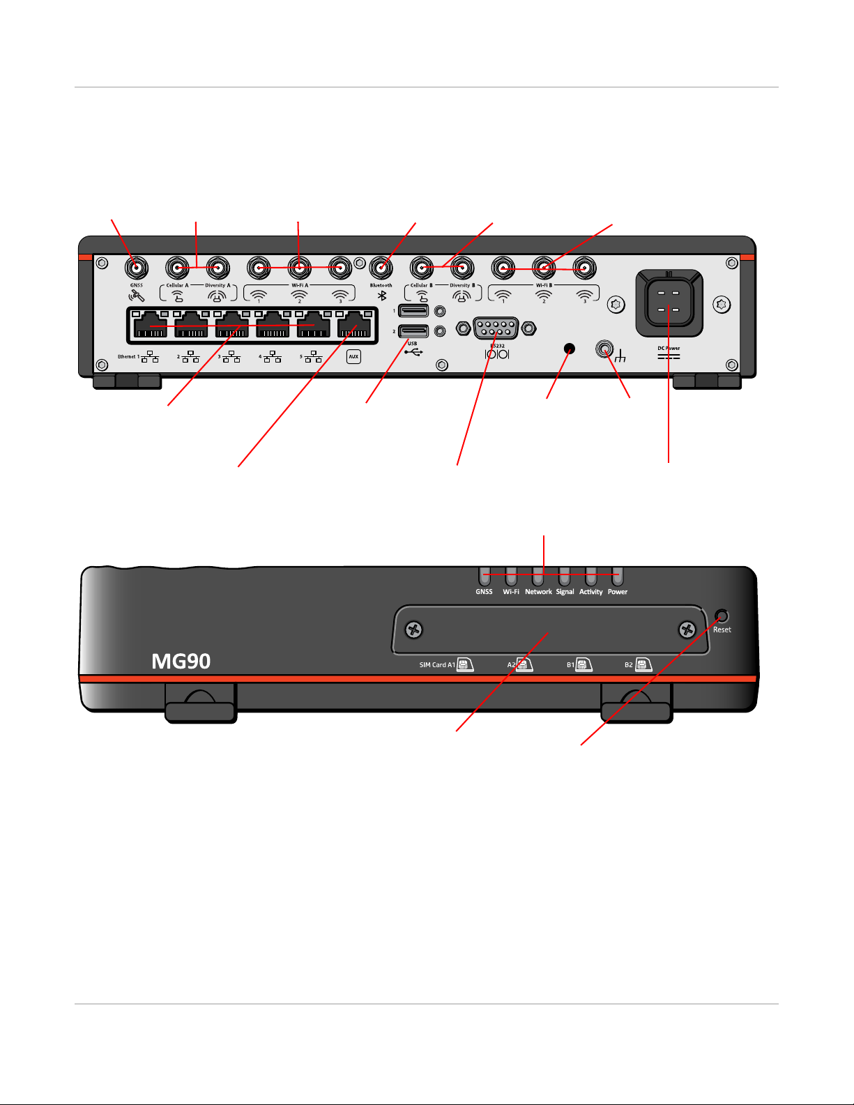
Description
SIM Card holders (See Insert the
SIM Card on page 18)
LEDs (See LED Behavior on page 26.)
(See Ethernet on page 32.)
RJ45 Ethernet Ports
RJ45 Aux Port
Locking USB 3.0 type-A Ports
(See USB on page 32.)
9-pin RS-232 Serial Port
(See Serial Port on page 33.)
Power Connector
(See Connect the Power on page 20.)
Antenna Connectors
Reset button
(See Reboot the MG90 and Reset the MG90 to
Factory Default Settings on page 29.)
GNSS Cellular A / Diversity A Wi-Fi A (Wi-Fi WAN)
(1/2/3)
Bluetooth Cellular B / Diversity B Wi-Fi B (Wi-Fi Access Point)
(1/2/3)
(See Connect the Antennas on page 18.)
Ground
Reprogram/Reset
Back
Panel
Front
Panel
(See Boot the MG90
from USB for Software
Update on page 29.)
(Reserved for future use)
Introduction to the MG90
Figure 1-1: MG90 Connectors, LEDs and SIM Card Holder
Rev 3 Feb.17 8 4118699
Page 9
AirLink MG90 Hardware User Guide
Power Modes
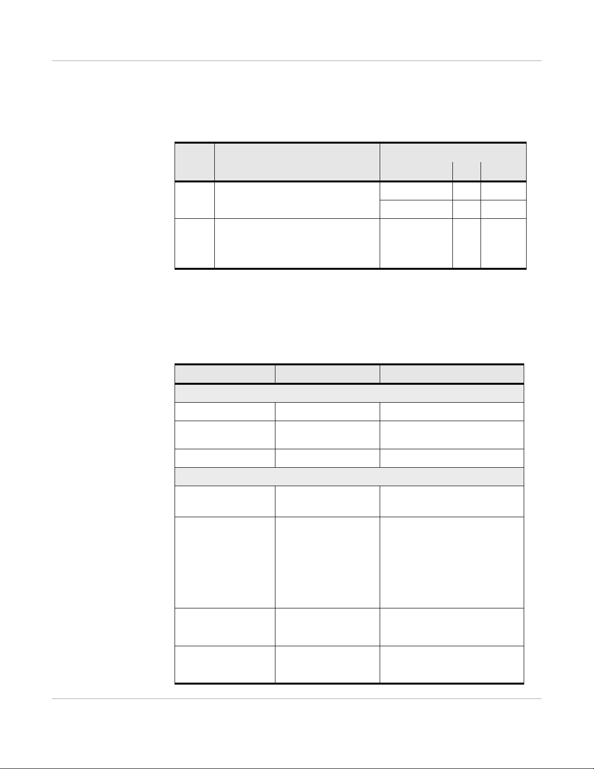
The Sierra Wireless MG90 has two power modes, as described in Table 1-1.
Table 1-1: MG90 Power Modes
Power Consumption
Mode Description
On Ignition on, CPU and radios ar e on
Ignition off, CPU and radios are off;
Standby
power is still connected.
Device can be woken by an I/O input or
at a configured time
Configuration Typ Max
1 Cellular radio 14 W 17 W
2 Cellular radios 18 W 21 W
- - <135 mW
Accessories
Table 1-2 lists accessories that are included with the MG90 router or are available for
purchase from Sierra Wireless.
Table 1-2: MG90 Accessories
Part Part Number Description
Included with router purchase
DC power cable 2000555 10’ power cable
SMA wrench 5400017
a
Used to install antenna cables to
MG90
Quick Start Guide 5302198 Basic setup and usage instructions
Available for separate purchase from Sierra Wireless
AC power adapter for
test bench use
Antenna packages
(Main)
Note: A secondary
antenna package is
also needed (for
Wi-Fi B and possible
second radio module)
Antenna package
(Secondary, for MG90
with one radio module)
Antenna package
(Secondary, for MG90
with two radio modules)
6001023
Contact Sierra Wireless
Sales for options.
Contact Sierra Wireless
Sales for options.
Contact Sierra Wireless
Sales for options.
• Universal adapter
• Voltage input: 100–240 VAC
• 6 antenna leads:
• (2) 3G/4G L TE
• (3) Wi-Fi
• (1) GNSS
• 3 antenna leads:
• (3) Wi-Fi
• 2 antenna leads:
• (2) 4G LTE
Rev 3 Feb.17 9 4118699
Page 10
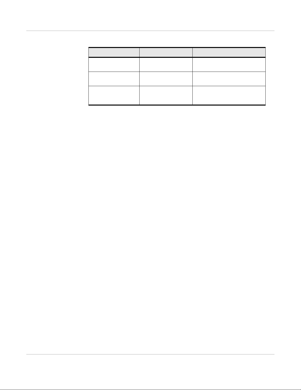
Table 1-2: MG90 Accessoriesa (Continued)
Part Part Number Description
Introduction to the MG90
Antenna for Bluetooth
Mounting bracket 6001024
GPIO Breakout Cable 6001095
a. Subject to change.
Contact Sierra Wireless
Sales for options.
Optional Bluetooth antenna with
SMA connector
Mounting bracket for easy vehicle
installation and removal
RS-232 GPIO breakout cable. See
GPIO Breakout Cable on page 50
for details.
Warranty
The MG90 comes with a 3-year warranty, and has an optional 2-year warranty
extension.
Rev 3 Feb.17 10 4118699
Page 11
2: Installation and Startup
This chapter describes:
• How to connect, install and start the MG90
• Front panel LEDs
• I/O functionality
Note: Field wiring and connections in hazardous locations must be
connected as per the wiring methods requirement for Class 2 circuits
mentioned in the National Electric Code and the Canadian Electric Code.
Note: The MG90 installation must be done by a qualified technician.
Powering the MG90 On
The MG90’s factory default configuration enables it to establish a
WAN connection if an appropriate SIM card is installed, and the APN
is configured correctly.
2
Note: Additional configuration is always recommended.
To start the MG90:
1. Apply power to the system:
· If the MG90 has been installed and wired into a vehicle's
electrical system, turn on the ignition.
· If the MG90 is not in a vehicle (for example, on a test bench),
use the optional AC power adapter.
The MG90 should fully power up within two minutes. When the
MG90 is turning on, the Power LED flashes green, then turns
solid green, and other LEDs begin to display their regular behavior. For more information on the LED patterns see LED Behavior
on page 26.
2. If the MG90 does not start automatically, press and release the
Reset button on the front panel.
3. Test the unit—Connect a test device (for example, a PC) to the
MG90 LAN via:
· Wi-Fi—An MG90 with factory default settings provides an
unsecured Vehicle Wi-Fi access point (AP) broadcasting its
own Serial Number as the SSID (e.g. ND60510068011018)
· Ethernet— Ethernet ports 1–4 (factory default configured for
LAN access)
Refer to the AirLink MG90 Software Configuration Guide for
configuration/ usage instructions.
Rev 3 Feb.17 11 4118699
Page 12

Installation and Startup
4. The MG90 is ready for use. However, you should further configure the unit using
the sections provided in this document.
Tools and Materials Required
• SIM card(s) (provided by your mobile network operator)—Depending on your
device configuration, you will have one or two cellular modems. Each modem can
support up to two SIM cards.
• #1 Phillips screwdriver
• Laptop computer with Ethernet cable
• Multi-element antenna(s) appropriate for your MG90. See Table 1-2 on page 9 for
suggested antennas.
• SMA wrench (provided with MG90)
• AC or DC power cable (available from Sierra Wireless or use your own custom
cable). See Table 1-2 on page 9 for part numbers.
• Optional— 9-pin connection cable for the RS-232 port
Caution: The MG90 has a hardened case for use in extreme environments. If the MG90 is to
be used in these environments, make sure to use cables designed and specified for this use to
avoid cable failure.
Installation Overview
The steps for a typical installation are performed as follows:
• Step 1—Insert the SIM Cards on page 12.
• Step 2—Mounting and Grounding the MG90 Chassis on page 14.
• Step 3—Connect the Antennas on page 18.
• Step 4—Connect the Data Cables on page 20.
• Step 5—Connect the Power on page 20.
• Step 6—Check the router operation on page 25.
• Step 7—Startup and Software Configuration on page 28.
Note: Depending on where you are installing the MG90, you may want to mount the router
before connecting the antenna, cables and power.
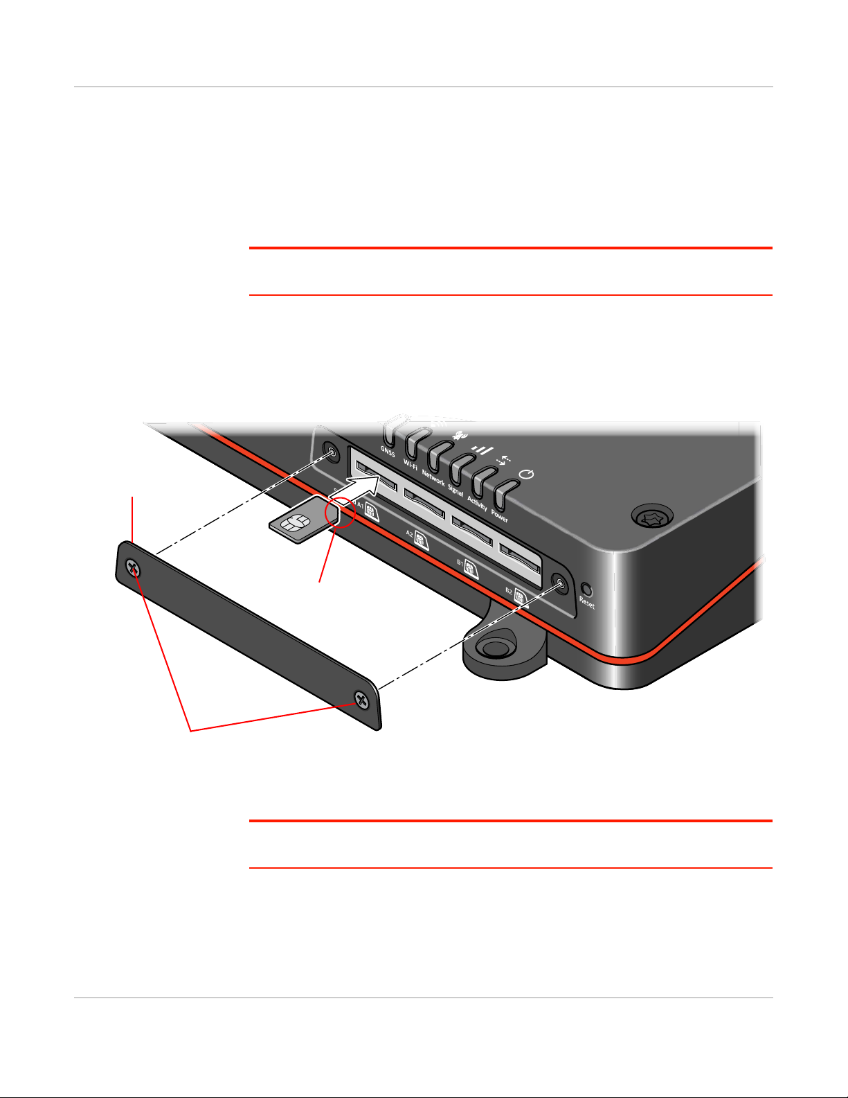
Step 1—Insert the SIM Cards
The MG90 has four mini-SIM (2FF) card slots—two slots for each radio module (up to
two radios). The card slots are located behind a removable plate on the front of the
device as shown in Figure 2-1 on page 13.
From left to right, the “SIM Card” slots are:
• A1—First radio module (Cellular A), first SIM
• A2—First radio module (Cellular A), second SIM
• B1—Second radio module (Cellular B), first SIM
• B2—Second radio module (Cellular B), second SIM
Rev 3 Feb.17 12 4118699
Page 13
AirLink MG90 Hardware User Guide
Note the orientation of notched
SIM card cover
#1 Phillips screws
corner for proper SIM card alignment.
If you are using only one SIM card for a radio module, Sierra Wireless recommends
that you install it in the module’s ‘1’ slot (e.g. SIM Card A1, SIM Card B1).
If the SIM card(s) are not already installed, insert them into the MG90 before
connecting any external equipment or power to the unit.
To install the SIM card(s):
1. Use a #1 Phillips screwdriver to remove the SIM card cover (2 screws).
Important: These are ‘captive’ screws that remain attached to the cover. Do NOT remove
them from the door.
2. Orient the SIM card(s), as shown in Figure 2-1 (Gold contacts on the SIM cards
face-up).
3. Gently slide the SIM cards into their slots until they click into place.
(To remove a SIM card, press the SIM card in until it clicks, and release it. Gently
grip the SIM card and pull it out.)
Rev 3 Feb.17 13 4118699
Figure 2-1: Installing the SIM Cards
4. Replace the SIM card cover.
Important: Do not over-tighten the screws. This could strip the threads inside the router,
which will prevent the cover from being re-attached.
Page 14
Installation and Startup
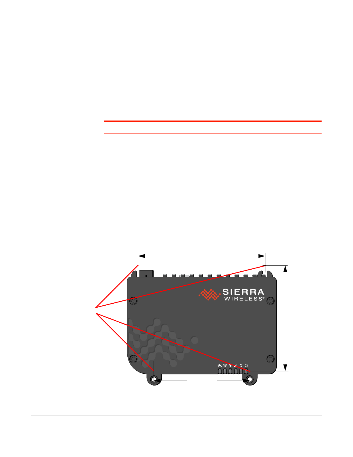
Mounting screw
holes/slots
200.0 mm
230.0 mm
170.0 mm
Step 2—Mounting and Grounding the MG90 Chassis
The MG90 should not be mounted in the driver’s area of the vehicle or in areas where
it can distract the driver. Mount it in accordance with accepted after-market practices
and materials.
While mounting the MG90:
• Make sure the power source is OFF.
Note: See the Mechanical Specifications on page 45 for the MG90’s dimensions.
Mount the router where:
• There is easy access for attaching the cables. Make sure there is sufficient space
in front, behind, and above the unit to connect all components and perform
maintenance.
Typical locations for installing the MG90 include under the deck lid, or on the
floorboard of the vehicle’s equipment storage.
• Cables will not be constricted, close to high amperages or exposed to extreme
temperatures
• The front panel LEDs are easily visible
• There is adequate airflow
• It is away from direct exposure to the elements, such as sun, rain, dust, etc.
• It will not be hit or come into contact with people, cargo, tools, equipment, etc.
The MG90 has 4 mounting holes/ slots, as shown in Figure 2-2. For screw
specifications, see Screw Torque Settings on page 34. For additional mechanical
dimension details, see Figure 3-3 on page 45.
Figure 2-2: MG90 Mounting Slots
Rev 3 Feb.17 14 4118699
Page 15
AirLink MG90 Hardware User Guide
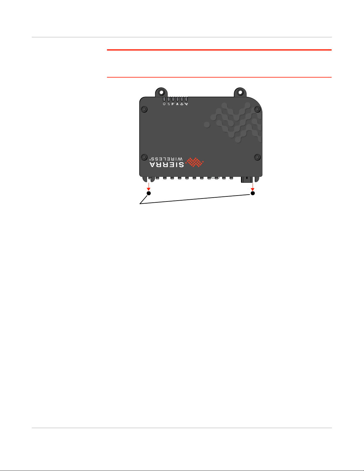
Mounting posts
Note: When mounting on a an inclined/vertical surface without the optional mounting bracket,
the MG90 should be positioned with the antenna ports facing down (or sideways) with the
mounting slots resting on mounting posts, as shown in Figure 2-3.
Figure 2-3: Recommended Orientation for Inclined/Vertical Mounting
Flat Surface Mount
If you are mounting the MG90 on a flat surface, use appropriate mounting screws.
Rev 3 Feb.17 15 4118699
Page 16

Installation and Startup
0.0
0.0
* all units in mm
Attach bracket to mounting surface and install MG90:
1. Pre-drill two screws into mounting surface.
2. Position mounting slots over screws.
3. Slide bracket down to ‘lock’ the screws in the tabs.
4. Secure the bracket with two more screws using appropriate mounting holes.
5. Position the MG90 as appropriate and secure to mounting bracket using the
screws provided with the bracket.
Bracket orientation for
horizontal mounting
Bracket orientation for
vertical mounting
260.0 267.4
218.0
19.2
209.2
156.8
79.8
35.0 225.0
96.3
173.3
77.0
190.0
Vehicle mounting holes
Green: Horizontal mount
Blue: Vertical mount
Bracket Mount
An optional mounting bracket (Part #6001024) is available from Sierra Wireless for
vertical mounting. This bracket comes is supplied with appropriate mounting screws.
Figure 2-4: MG90 Bracket Mounting Installation Examples
Rev 3 Feb.17 16 4118699
Page 17

AirLink MG90 Hardware User Guide
Ground
Ground the MG90 Chassis
For DC installations (with a fixed “system” ground reference), Sierra Wireless strongly
recommends always grounding the MG90 chassis to this system ground reference.
To ensure a good grounding reference connect one end of a short 18 AWG or larger
gauge wire with a ring terminal connector to the ground terminal on the rear panel of
the MG90 and connect the other end to the vehicle chassis.
The ground terminal requires an M4x 6 mm screw (or longer, depending on the ring
terminal connector size.)
Figure 2-5: Ground Connector (Rear Panel)
Cabling—Best Practices
Separate MG90 antenna, data, and power cables from other wiring in the vehicle and
route away from sharp edges.
Cable Strain Relief
Sierra Wireless recommends using cable strain relief for installations in high-vibration
environments.
Place the cable strain relief within 200 mm (8") of the MG90 to reduce the mass of
cable supported by the power connector under vibration. Ideally, the strain relief
mounting for the DC cable should be attached to the same object as the MG90, so
both the router and cable vibrate together. The strain relief should be mounted such
that it does not apply additional stress on the power connector (i.e. the cable should
not be taut and should not pull the power connector at an angle).
Cable Management
Proper cable management eliminates unnecessary installation complications, allows
for ease of maintenance, and prolongs cable longevity.
Rev 3 Feb.17 17 4118699
Page 18

Installation and Startup
GNSS
Cellular A Diversity A
Wi-Fi A (Wi-Fi WAN)
Bluetooth Cellular B Diversity B
Wi-Fi B (Wi-Fi Access Point)First Radio Second Radio (if installed)
12 3
12 3
When installing cables, adhere to the following practices:
1. Label each cable that attaches to the MG90. For example: “GNSS”, “Wi-Fi A”,
“Ethernet to Device X”.
2. Protect the cables using a proper cable conduit.
3. Secure each cable connected to the MG90 via a permanent fixture.
Step 3—Connect the Antennas
Warning: This router is not intended for use close to the human body. Antennas should be at
least 8 inches (20 cm) away from the operator or bystanders.
The MG90 has the following SMA antenna connectors:
Figure 2-6: Antenna Connectors (Rear Panel)
Table 2-1: Antenna Connector Types
Module Connectors Description Type
Radio
Radio
GNSS GNSS GNSS SMA
Wi-Fi
Wi-Fi
Bluetooth Bluetooth Bluetooth RP-SMA
Cellular A First radio, Rx/Tx SMA
Diversity A First radio, Rx Diversity SMA
Cellular B Second radio, Rx/Tx SMA
Diversity B Second radio, Rx Diversity SMA
Wi-Fi A 1
Wi-Fi A 2 RP-SMA
Wi-Fi A 3 RP-SMA
Wi-Fi B 1
Wi-Fi B 2 RP-SMA
Wi-Fi B 3 RP-SMA
• Wi-Fi 802.11b/g/n/ac, 3x3 MIMO
• Used for Wi-Fi WAN (Default configu-
ration)
• Wi-Fi 802.11b/g/n/ac, 3x3 MIMO
• Used for Wi-Fi access point (Default
configuration)
RP-SMA
RP-SMA
Rev 3 Feb.17 18 4118699
Page 19

AirLink MG90 Hardware User Guide
Slips over connector
Open channel for cable
Use the wrench to
hand-tighten (or loosen)
SMA connectors
For regulatory requirements concerning antennas, see Maximum Antenna Gain on
page 47.
To install the antennas:
1. Mount the antenna unit(s) on the vehicle (typically multi-element units):
· Follow the antenna unit’s recommended installation instructions.
· Use appropriate cable strain relief. (See Cable Management on page 17.)
· When mounting antenna unit(s) containing WAN/WLAN cellular antennas,
make sure there is at least 20 cm between the antenna(s) and the user or
bystanders during normal operation.
· If the unit includes a GNSS antenna, make sure it has a good view of the sky
(at least 90
Note: If single-element antennas are installed, refer to Table A-1 on page 49 for recommended
antenna separation.
⁰).
Note: Use the SMA
wrench provided to handtighten the antennas to the
SMA connectors. Do not
over-tighten.
Recommended torque is
0.6–0.8 Nm (5–7 in-lb),
and max torque should not
exceed 1.1 Nm (10 in-lb.).
2. Connect the cables from the antenna units to their corresponding SMA/RP-SMA
connectors on the MG90’s rear panel.
From left to right (as shown in Figure 2-6 on page 18):
· If used, connect the GNSS antenna to the “GNSS” antenna connector.
· For the first radio module:
· Connect the main antenna to the “Cellular A” connector.
· If used, connect the diversity antenna to the “Diversity A” connector.
· Connect the Wi-Fi Access Point module’s three antennas to the “Wi-Fi A”
connectors.
· If used, connect a Bluetooth antenna to the “Bluetooth” connector.
· For the second radio module:
· Connect the main antenna to the “Cellular B” connector.
· If used, connect the diversity antenna to the “Diversity B” connector.
· Connect the Wi-Fi WAN module’s three antennas to the “Wi-Fi B” connectors.
Note: If the antenna unit(s) is located away from the router, keep cables as short as possible to
prevent the loss of antenna gain. Route the cables to protect them from damage or being
snagged or pulled. There should be no binding or sharp corners in the cable routing. Excess
cabling should be bundled and tied off. Make sure the cables are secured so their weight will
not loosen the connector from the router over time.
Rev 3 Feb.17 19 4118699
Figure 2-7: SMA Wrench Usage
Page 20

Installation and Startup
Ethernet
(5 ports)
12345
Reserved for USB1 Serial (RS-232)
future use
USB2
Step 4—Connect the Data Cables
The MG90 has multiple ports for connecting optional data cables or accessories:
• Ethernet (10/100/1000 Base-T RJ45) ports (5)
Use Cat 5e or Cat 6 Ethernet cables to connect up to five devices.
· Ports 1–4: LAN (Default)
· Port 5: WAN (Default)
• AUX port reserved for future use
• USB 3.0 type-A locking ports. For USB port details, see USB on page 32.
To connect a USB cable/device:
a. Plug the USB cable/device into either USB port.
b. If using a USB locking cable, screw the jack screw finger-tight.
• Serial Port (9-pin RS-232)
See Serial Port on page 33 for cable requirements.
Figure 2-8: Data Cable Connectors (Rear Panel)
Step 5—Connect the Power
The router’s power supply cable must be connected to the vehicle’s fuse box, and
installed along the vehicle wall, always inside the vehicle cabin and must not cross the
vehicle’s firewall protection. Always follow the vehicle manufacturer’s
recommendations for electrical accessories connections. All components used in the
electrical connection to the vehicle should be UL Listed.
The MG90 comes with a 3 meter (10 ft.) DC power cable.
You can also purchase an optional AC adapter for test bench usage—see Table 1-2
on page 9.
Note: Electrical installations are potentially dangerous and should be performed by personnel
thoroughly trained in safe electrical wiring procedures.
Rev 3 Feb.17 20 4118699
Page 21

AirLink MG90 Hardware User Guide
1
43
Pin 1 - Red
Power
Pin 2 - Black
Ground
Pin 3 - White
Ignition Sense
Pin 4 - Green
GPIO
2
For more information,
see wiring diagrams on page 23.
The MG90 supports an operating voltage of 7 V–36 V, but since low voltage standby
mode is enabled by default, you must supply more than 11 volts at startup.
If you want to operate the router at a lower voltage, you can change the low voltage
standby settings once the router is up and running. For more information, refer to the
MG90 Software Configuration User Guide.
Fusing
For DC installations, Sierra Wireless recommends fusing the power input using a 9 A,
fast blow fuse, recommended to have no more than ± 10% de-rating over the
operating temperature range.
DC Voltage Transients
The MG90 has built-in protection against vehicle transients including engine cranking
(down to 5.0V) and load dump, so external power conditioning circuits are not
needed. For details, see Industry Certification for Vehicles on page 30.
MG90 Power Connector
Rev 3 Feb.17 21 4118699
Figure 2-9: DC Power Cable Connections (Colors indicate DC cable wire colors.)
Page 22

Installation and Startup
Table 2-2: Power Connector Pin and DC Cable Wires
Associated DC
Pin Name
1 Power Red
2 Ground Black Main device ground PWR
Ignition
3
Sense
Cable Wire Color Description Type
Note: If you want to turn the MG90 on/off using a control line, such as a vehicle
White
ignition line, Sierra Wireless strongly recommends that you connect the control/
ignition line to Pin 3 and apply continuous power on Pin 1.
Main power supply for device
Note: If you do not connect Pin 3 to the ignition, you MUST connect it to the
positive terminal of your power supply or battery. If you are using a Sierra
Wireless AC adapter, the connection is inside the cable.
Ignition Sense: Connected to the vehicle ignition or an external switch. The MG90
is off when this pin is either open-circuit or grounded, and on when this pin is
connected to power.
PWR
I
4 GPIO Green
General purpose digital input/output. For more information, see I/O Configuration
on page 24.
I/O
Connect the Router to the Vehicle’s Electrical System
To connect the MG90 router to the vehicle’s electrical system:
1. Make sure the vehicle is turned off.
2. Remove the key from the ignition.
3. Disconnect the vehicle’s battery:
a. Disconnect the negative terminal first.
b. Disconnect the positive terminal.
4. Connect the black (ground) wire on the DC power cable to the vehicle chassis.
5. Make sure the MG90 is grounded. (See Step 2—Mounting and Grounding the
MG90 Chassis on page 14.)
6. Use a 9 A, fast blow fuse, recommended to have no more than ± 10% de-rating
over the operating temperature range, to connect the red (power) wire on the DC
power cable to the vehicle’s fuse box. (See Figure 2-10.)
7. Connect the white wire (ignition) on the DC power cable to the ignition signal from
the vehicle.
8. Connect the DC power cable to the MG90.
9. Reconnect the vehicle’s battery:
a. Connect the positive terminal first.
b. Connect the negative terminal.
Rev 3 Feb.17 22 4118699
Page 23

AirLink MG90 Hardware User Guide
MG90 power plug
Power (Red wire)
Ignition Sense (White wire)
I/O (Green wire)
Ground (Black wire)
-+
Battery
Ignition
1
3
4
2
Engine compartment Vehicle cabin
Vehicle firewall
Vehicle fuse box
9 A fuse
Note: If the I/O pin is not used, leave the
green wire unterminated.
Wiring Diagrams
Recommended Basic Vehicle Installation
For most vehicle installations, Sierra Wireless recommends connecting the white
Ignition Sense wire to the vehicle’s ignition switch, as shown in Figure 2-10.
Figure 2-10: Recommended Vehicle Installation
The recommended vehicle installation allows the router to operate with the vehicle.
When the vehicle ignition is off, the MG90 is in standby mode. If desired, you can
configure a delay between the time the vehicle’s ignition shuts off, and the time the
router shuts down. A delayed shutdown is especially useful if you want to maintain a
network connection while the vehicle’s engine is shut off for short periods, such as in
a delivery vehicle.
• Pin 1 (Power) —Use the red wire in the DC cable to connect Pin 1 to the power
source. Include a 9 A, fast blow fuse, recommended to have no more than ± 10%
de-rating over the operating temperature range, in the input power line. Sierra
Wireless recommends using a continuous (unswitched) DC power source.
Connect the power through the vehicle’s fuse box.
• Pin 2 (Ground)—Use the black wire in the DC cable to connect Pin 2 to the
vehicle battery’s negative terminal, or ground. See also Step 2 — Mounting and
Grounding the MG90 Chassis on page 14.
• Pin 3 (Ignition Sense) —Sierra Wireless recommends always using the Ignition
Sense wire (Pin 3) to turn the router off. It should not be turned off by disconnecting the power.
• Pin 4 (GPIO)—This pin can remain unconnected if GPIO functionality is not
required. Otherwise, connect the GPIO as described in the I /O Configuration on
page 24.
Rev 3 Feb.17 23 4118699
Page 24

Installation and Startup
4
DC Power ConnectorRS-232 Connector
14
69
MG90 router
Off (default)
3.3V
V
High
2.1 V
Protection
circuitry
Internal Pull-up
Resistor
Digital
input
Pin 4 on the power connector, or
Pin 1, 5, 6, or 9 on the RS-232
connector
I/O Configuration
The MG90 has five pins you can use for digital input configuration (digital output to be
supported by a future software update):
• Pin 4 on the power connector
• Pins 1, 4, 6, and 9 on the RS-232 serial connector
Figure 2-11: I/O Pin-out for RS-232 Connector and Power Connector
You can use these pins as:
· Digital inputs—See Figure on page 25.
· High side pull-ups/ dry contact switch inputs— See Figure 2-13 on page 25.
Digital Input
You can connect any of the GPIO pins to a digital input to detect the state of a switch,
or to monitor an external device such as a motion detector, a remote solar panel, or a
remote camera. Digital input can also be used with the standby timer. While in
Standby mode, the digital input will not be acted upon if it changes state.
Rev 3 Feb.17 24 4118699
Figure 2-12: Digital Input
Page 25

AirLink MG90 Hardware User Guide
MG90 router
On
3.3V
I
Source
= 1.1 mA (Typical)
Protection
circuitry
Internal Pull-up
Resistor
Output Off (default)
Pin 4 on the power connector, or
Pin 1, 5, 6, or 9 on the RS-232
connector
Table 2-3: Digital Input
Pull-up State Minimum Typical Maximum Units
Low — — 0.7 V
Off
High 2.1 3.3 36 V
a. Voltage levels are compatible with 3.3V TTL standard logic families.
a
High Side Pull-up / Dry Contact Switch Input
You can connect any of the GPIO pins to a dry contact switch, such as an alarm relay.
While in Standby mode, the dry contact switch input will not be acted upon if it
changes state.
Figure 2-13: High Side Pull-up / Dry Contact Switch Input
Table 2-4: High Side Pull-up / Dry Contact Switch Input
Minimum Typical Maximum Units Comments
Source Current - 1.1 - mA
Amount of current the external
switch must sink
Step 6—Check the router operation
1. With the ignition OFF (or AC power unplugged if using an adapter), attach the
power cable connector to the power socket on the rear panel of the MG90.
Line up the locking ‘key’ on the power cord with the corresponding slot on the
Rev 3 Feb.17 25 4118699
power socket and fully insert the connector. The lock snaps into place when the
cord is correctly inserted. This protects the power cord against accidental disconnection caused by vehicle vibrations.
Page 26

Installation and Startup
Locking connector
GNSS Wi-Fi Network Signal Activity Power
Figure 2-14: Power Cable Locking Connector
2. When power is supplied to the MG90, it powers up automatically. If it does not
turn on, make sure that the:
· Power connector is plugged in and supplying voltage greater than 11 V.
Note: Although the MG90 operates in the range 7 V–36 V, low voltage
standby mode is enabled by default, so in order to avoid the router powering
on in standby mode, ensure that it is supplied with more than 11 V at startup.
· Ignition Sense (pin 3) is connected to the battery or power source (see Step
5—Connect the Power on page 20 for details)
LED Behavior
Figure 2-15: MG90 LED Status Indicators (front panel)
Table 2-5: LED Behavior
LED Color/Pattern Description
GNSS
Solid Green Satellite fix available
Flashing Amber No satellite fix available
Off GNSS is off /disabled
Rev 3 Feb.17 26 4118699
Page 27

AirLink MG90 Hardware User Guide
Table 2-5: LED Behavior (Continued)
LED Color/Pattern Description
Solid Green Wi-Fi enabled (any mode), and not connected to an access point
Flashing Green Transmitting/receiving over Wi-Fi while not connected to an access point
Wi-Fi
Network
Signal
Activity
Solid Amber
Flashing Amber Transmitting/receiving over Wi-Fi while connected to an access point
Off Wi-Fi is off
Flashing Amber Connecting to a network
Flashing Green Connected to WAN (over cellular, Wi-Fi, or Ethernet)
Solid Green Connected to VPN
Off No network connection
Wi-Fi connected to an access point (i.e. Network state is “Network Ready Wi-Fi”
If the active WAN link is:
• Cellular—Signal shown is for the cellular radio for that link.
• Other (Wi-Fi, Ethernet, etc.)—Signal shown is for the strongest cellular
radio.
Solid Green Good signal ( 85 dBm; equ ivalent to 4–5 bars)
Solid Amber Average signal ( -100 dBm, <-85 dB; equivalent to 2–3 bars)
Red Poor signal ( -100 dBm; equivalent to 1 bar)
Flashing Green Transmitting/receiving over the WAN interface
Off No WAN activity
Solid Green Power is present, normal operation
Flashing Green Power is present, MG90 is booting
Solid Amber Standby mode
Power
Flashing Red
• Slow blink (1 per second)—Temperature out of operating range (see
Temperature (operational) on page 31)
• Fast blink (4 per second)—Voltage out of operating range
Off No power
Green LED chase Radio module update is in progress
ALL LEDS
Note: A ‘chase’ is all
LEDS blinking in
sequence.
Amber LED chase Software update is in progress
Factory default reset is in progress
Solid White
When the factory reset finishes, the MG90 will power off and, if AutoPower
is enabled (LCI General > Startup tab), will reboot.
Rev 3 Feb.17 27 4118699
Page 28

Installation and Startup
Ethernet LEDs
The connector has two LEDs that indicate speed and activity. When looking into the
connector:
• Activity—The right LED indicates the link status:
· Solid Amber—Link
· Blinking Amber—Activity
· Off—No link
• Connection Speed—The left LED indicates the Ethernet connection speed:
· Solid Green— 1000 Mbps (Gigabit)
· Off—10/100 Mbps
Step 7—Startup and Software Configuration
You can configure the MG90 using the browser-based Local Configuration Interface
(LCI). The utility presents configuration pages under a series of tabs and sub-tabs.
To access the LCI:
1. Connect a laptop to the router with an Ethernet cable— use any of the Ethernet
ports 1–4. (By default, ports 1–4 are configured as LAN connections and port 5 is
configured as a WAN connection.).
2. Launch your web browser and go to 172.22.0.1/MG-LCI. (Note that the URL is
case-sensitive.)
Figure 2-16: LCI Login Screen
3. Enter the default User name and Password, and click Login:
· User Name: admin
· Password: admin
4. Refer to the MG90 Software Configuration User Guide for details on using the LCI
to configure your MG90.
In general, when using LCI:
· Most configuration changes take effect immediately. However, changes
related to the serial port take effect only after the MG90 reboots.
· Your browser’s Forward and Back controls can be used to navigate through
the LCI.
Rev 3 Feb.17 28 4118699
Page 29

AirLink MG90 Hardware User Guide
· If you make any configuration changes on a screen, you must click Save to
save and apply them before changing screens. If you do not click Save, your
changes will be lost.
5. When finished configuring the MG90, click the Logout tab to return to the login
screen.
Figure 2-17: Log Out of LCI Using Logout Tab
Reboot the MG90
To reboot the MG90:
• On the front of the unit, press and release the Reset button.
Reset the MG90 to Factory Default Settings
To reset the router to the factory default settings:
1. On the front of the unit, press the Reset button for the ‘Button Reset Time’
configured in the LCI’s General > Shutdown tab (factory default is 10 seconds).
2. When all the LEDs turn solid white, release the Reset button.
When the factory reset is complete, the MG90 powers off and, if AutoPower is
enabled (LCI General > Startup tab), will reboot.
Boot the MG90 from USB for Software Update
To boot the MG90 from a USB flash drive that is loaded with a software update
package (for cases when the MG90 cannot be upgraded OTA (over the air)):
1. Insert the USB flash drive in either USB slot on the back panel.
2. On the back panel, press and hold the Reprogram/ Reset button and apply power,
then release the button.
Rev 3 Feb.17 29 4118699
Page 30

3: Specifications
This chapter describes the MG90 router specifications, RF band and Tx power
specifications, Wi-Fi support, and mechanical specifications.
Router Specifications
The following table describes general router specifications.
Table 3-1: General Router Specifications
3
Certification and
Interoperability
Reliability MTBF (Ground Benign, 25°C)— 203,409 hours (23.22 years)
Emissions/Immunity • CE (Including EMC Test case for vehicle installation EN301489)
• ACMA RCM
• FCC
• Industry Canada
Safety • CB Scheme
• UL 60950
Industry Certification for
Vehicles
Environmental
Compliance
GSM/UMTS
Certifications
• E-Mark (72/245/EEC, 2009/19/EC)
• ISO7637-2
• SAE J1455 (Shock & Vibration)
• RoHS 2011/65/EU (RoHS 2)
• WEEE
• PTCRB
• GCF-CC
• R&TTE
MTBF calculations are performed per Telcordia “Reliability Prediction
Procedure for Electronic Equipment” document number SR-332,
Method 1, Issue 3
Rev 3 Feb.17 30 4118699
Page 31

AirLink MG90 Hardware User Guide
Table 3-1: General Router Specifications (Continued)
Environmental
Testing
Mobile Network Operator Certification • Verizon Wireless
Vibration (operational) MIL-STD-810G, test methods 514.6, 527
Composite Wheeled Vehicle
Shock (operational) MIL-STD-810G, test method 516.6-I
SAE J1455 (Shock and
Vibration) for heavy-duty
vehicles
Temperature
(operational)
Temperature
(non-operational)
Thermal shock MIL-STD-810G, test method 503.5
Humidity (operational) MIL-STD-810G, test method 507.5
Ingress Protection (IP)
rating
Drop (non-operational) ISTA 2A 2001, test categories 1, 4, 5, and 6
Procedure I—Functional Shock
• Vibration: Section 4.10.4.2 Cab Mount
• Shock: Section 4.11.3.4 Operational Shock
• Electrical: 12 and 24 V systems
Section 4.13.1—12 and 24 V
Section 4.13.2—SAE J1113-11 Level 3
MIL-STD-810G, test methods 501.5, 502.5
(-30° to +70°C)
MIL-STD-810G, test methods 501.5, 502.5
(-40° to +85°C)
5–95% RH, non-condensing
IP64 (if RJ45 and USB connectors are covered)
• AT&T
• Other major network operators pending
Network
Technology
Host Interfaces Antenna connectors SMA connectors:
LTE
DC-HSPA
For SKU-specific lists of supported bands, see Radio Bands/
Conducted Tx Power on page 36.
• GNSS (all units)
• Cellular A (all units)—Connects to first cellular radio
• Diversity A (all units)—Connects to first cellular radio
• Cellular B (units with 2 cellular modules)—Connects to second
cellular radio
• Diversity B (units with 2 cellular modules)—Connects to second
cellular radio
RP-SMA connectors:
• Wi-Fi A (3 connectors) (all units) —Used for Wi-Fi WAN (default
configuration)
• Wi-Fi B (3 connectors) (all units)—Used for Wi-Fi Access Point
(default configuration)
• Bluetooth (all units)
Rev 3 Feb.17 31 4118699
Page 32

Table 3-1: General Router Specifications (Continued)
USB
Note: Do not use the USB ports in a potentially explosive
environment.
• USB 3.0 Type A port, complies with USB Version 3.0 specifi-
cation
• Port supports use of SeaLATCH Type A USB locking connectors
Figure 3-1: USB Type A Locking Connector
• Ports are available for using a flash drive for offline software
upgrade if the unit is functional but is unable to be upgraded
OTA (Over The Air)
• The MG90 Software Configuration User Guide contains the
details of USB mode configuration and driver installation.
Specifications
Ethernet • (5) Gigabit (10/100/1000 Base-T) RJ45 Ethernet ports
• IEEE 802.3 Ethernet specification for 1000 Mbps speed (Gigabit
Ethernet) with fallback to 100 or 10 Mbps (Cat 5e or Cat 6 cable
is required for Gigabit Ethernet)
• Auto-crossover support
• Auto-negotiation detects the speed of the connecting device
Auxiliary Input • Reserved for future use
• RJ45 port
Rev 3 Feb.17 32 4118699
Page 33

AirLink MG90 Hardware User Guide
12 3 45
6789
Table 3-2: Serial Connector Pin-out
Name Pin Description Type
DCD 1 GPIO4
a
a. GPIO pins are digital input only. Digital output to be supported by
future software update.
IN/OUT
RXD 2 Receive Data IN
TXD 3 Transmit Data OUT
DTR 4 GPIO2
a
IN/OUT
GND 5 Main GND. Connected internally to
BOARD GND
GND
DSR 6 GPIO3
a
IN/OUT
RTS 7 Ready To Send OUT
CTS 8 Clear To Send IN
RI 9 GPIO1
a
IN/OUT
Table 3-1: General Router Specifications (Continued)
Serial Port • 9-pin RS-232 serial port configured as DTE, connects directly to
most computers or other devices with a null-modem cable with
handshaking
Note: If you have a DTE device, you need to use a null modem
(cross-over) cable with handshaking.
• Used for connecting serial devices and configuration
• Provides access to MG90’s four GPIOs via pins 1, 4, 6, 9
• Complies with the EIA RS-232D specification for DTE equipment
Figure 3-2: DB-9 Male Serial Connector
Note: An RS-232 GPIO Breakout Cable is available. See GPIO
Breakout Cable on page 50 for details.
SIM Card Interface • Four mini-SIM (2FF) slots—Two for each installed radio module
Rev 3 Feb.17 33 4118699
• 1.8 V/3.3 V.
• This interface is compliant with the applicable 3GPP standards
for USIM.
Page 34

Table 3-1: General Router Specifications (Continued)
Input/Output GPIOs:
• Configurable I/O pin on power connector
• GPIOs (4)—Connector type: RS-232 DB9 serial connector (see
Serial Port on page 33)
Uses:
• Digital input with optional pullup (see Digital Input on page 24)
• Open drain output with 500 mA sink capability
Power Adapter Pins 4-Pin connector:
• Power
• Ground
• Configurable GPIO (digital I/O)
(Output to be supported by future software update.)
• Configurable ignition sense
Reset Manual reset button on front panel
Specifications
LEDs
For more information, see page 26.
6 LEDs:
• GNSS
• Wi-Fi
• Network
• Signal
• Activity
• Power
Mechanical Specifications • Weight
· 5.3 lb/2.4 kg
• Dimensions
· Width: 10.6 in / 27.0 cm
· Depth: 8.7 in / 22.0 cm
· Height: 2.4 in / 6.0 cm
• Housing—The MG90 is made of ruggedized powder-coated
aluminum.
• RoHS—The MG90 complies with the Restriction of Hazardous
Substances Directive (RoHS). This directive restricts the use of
six hazardous materials in the manufacture of various types of
electronic and electrical equipment.
Screw Torque Settings • Mount screws (M6)— 40 kgf/cm (3.92 Nm/35 in-lb). Screws are
included with the optional mounting bracket.
• Antennas—Use the SMA wrench provided to hand-tighten the
antennas to the SMA connectors. Do not over-tighten. Recommended torque is 0.6–0.8 Nm (5–7 in-lb), and max torque
should not exceed 1.1 Nm (10 in-lb).
Operating Voltage Input voltage: 7–36V
Power Consumption Power state:
• ON:
· 1 cellular radio—14 W (typ), 17 W (max)
· 2 cellular radios—18 W (typ), 21 W (max)
• Standby—< 135 mW (max)
Rev 3 Feb.17 34 4118699
Page 35

AirLink MG90 Hardware User Guide
Table 3-1: General Router Specifications (Continued)
Conducted Electrical Transients • Compliant to ISO 7637-2:2004:
· Load dump specifications—Test Pulses 1, 5a, 5b
· Harness transient specifications—Test Pulses 2a, 2b, 3a, 3b
· Cranking specification—Test Pulse 4
• Tolerates +200 V/-600 V spikes
• Uninterrupted operation during brownouts down to 5V
GNSS Technology • Embedded 48 channel GNSS receiver with active antenna
support
• Satellite systems supported:
· GPS, GLONASS, COMPASS (BeiDou-2)
· Galileo, QZSS (Future software support)
• Protocols: NMEA and TAIP messaging
• Local and remote forwarding via TCP or UDP
• Local and remote forwarding via serial port
• Dead reckoning (future release)
Protocols • Network: TCP/IP, UDP/IP, DNS, IPv4
• Routing: NAT, Host Port Routing, DHCP, VLAN
• GPS: NMEA, TAIP
Vehicle Area Networking (LAN) • Support for all on-board devices - wired and wireless
· IEEE 802.11 b/g/n/ac (built-in vehicle AP)
· 10/100/1000 Base-T Ethernet - RJ45 x 5 ports
· Bluetooth
· Serial—RS-232 DB-9
· DHCP Server (RFC 2131)
· USB - USB 3.0 x 2, Type A (female)
• Compatibility
· Operates with Wi-Fi certified client devices
· Supports all major client operating systems
Wide Area Networking (WAN) • Wireless Networking
· For SKU-specific lists of supported bands, see Radio Bands/
Conducted Tx Power on page 36.
· Optional support for LTE B14 (FirstNe t Public Safety Band 14)
· Integrated compatibility with current wireless WAN standards
including HSPA, HSPA+, 4G LTE Advanced.
· IEEE 802.11 b/g/n/ac
· Ethernet WAN devices (e.g. satellite modem)
• Transmit video and data through the MG90
· QOS - Application priority queuing
Rev 3 Feb.17 35 4118699
Page 36

Table 3-1: General Router Specifications (Continued)
Specifications
Security Secure all data
transmitted to and from
vehicle without need for
VPN client software on
devices.
• WLAN Security and Authentication
· WEP, WPA, WPA2
· Key management WPA-PSK and WPA-EAP
• Firewall
· Port forwarding
· Port blocking
• Encryption
· IPSec including LAN to LAN, Host to LAN, IKEV2, MOBIKE
• Authentication and Accounting
· 802.1x/RADIUS authentication
Management Manage mobile network, vehicle and network health when operated
with AMM.
• Management
· Operational support services for fault, configuration,
accounting, performance and security
· Network coverage reporting
· Location-based reporting
· Historical logging
· Remote software updates
· Secure VNC reach-through
· Email alerts for configurable thresholds
Radio Bands/Conducted Tx Power
The radio frequency bands supported by the MG90 vary by SKU configuration.
Table 3-3: SKU Configurations
SKU Cellular Radios Region
1102695 Single LTE-A radio North America/Europe
1102716 Dual LTE-A radios North America/Europe
1103007 Single LTE-A radio with
Band 14 LTE radio
1103239 Single LTE-A radio Asia/Pacific
1103240 Dual LTE-A radios Asia/Pacific
Note: The radio module types in your MG90 are listed in the Local Configuration Interface’s
WAN Link Status screen (Status > WAN).
North America
Rev 3 Feb.17 36 4118699
Page 37

AirLink MG90 Hardware User Guide
SKU 1102695/1102716 (North America/Europe)
The following tables indicate supported radio frequency bands and conducted
transmit power specifications for SKU #1102695 and #1102716.
Table 3-4: Supported Bands (SKU #1102695 / 1102716)
Radio
Technology
LTE Band 1 1920–1980 MHz 2110–2170 MHz
Band Frequency (Tx) Frequency (Rx)
Band 2 1850–1910 MHz 1930–1990 MHz
Band 3 1710–1785 MHz 1805–1880 MHz
Band 4 1710–1755 MHz 2110–2155 MHz
Band 5 824–849 MHz 869–894 MHz
Band 7 2500–2570 MHz 2620–2690 MHz
Band 8 880–915 MHz 925–960 MHz
Band 12 699–716 MHz 729–746 MHz
Band 13 777–787 MHz 746–756 MHz
Band 20 832–862 MHz 791–821 MHz
Band 25 1850–1915 MHz 1930–1995 MHz
Band 26 814–849 MHz 859–894 MHz
Band 29 n/a 717–728 MHz
Band 30 2305–2315 MHz 2350–2360 MHz
Band 41 2496–2690 MHz (TDD)
WCDMA Band 1 1920–1980 MHz 2110–2170 MHz
Band 2 1850–1910 MHz 1930–1990 MHz
Band 3 1710–1785 MHz 1805–1880 MHz
Band 4 1710–1755 MHz 2110–2155 MHz
Band 5 824–849 MHz 869–894 MHz
Band 8 880–915 MHz 925–960 MHz
Rev 3 Feb.17 37 4118699
Page 38

Table 3-5: Conducted Tx Power (SKU #1102695 / 1102716)
Specifications
Band Conducted Tx
Power (dBm)
LTE
Bands 1, 2, 3, 4, 5, 8, 12, 13, 20, 25, 26 +23±1
Bands 7, 30, 41 +22±1
UMTS
Band 1 (IMT 2100 12.2 kbps)
Band 2 (UMTS 1900 12.2 kbps)
Band 3 (UMTS 1800 12.2 kbps)
Band 4 (AWS 1700/2100 12.2 kbps)
Band 5 (UMTS 850 12.2 kbps)
Band 8 (UMTS 900 12.2 kbps)
+23±1 Connectorized (Class 3)
Notes
Table 3-6: GNSS Bands Supported (SKU #1102695 / 1102716)
Band Frequency
GPS 1575.42 MHz
GLONASS 1602 MHz
COMPASS (BeiDou-2) 1561.098 MHz
Galileo
QZSS
Future software support
Rev 3 Feb.17 38 4118699
Page 39

AirLink MG90 Hardware User Guide
SKU 1103007 (North America)
The following tables indicate supported radio frequency bands and conducted
transmit power specifications for SKU #1103007.
Table 3-7: Supported Bands (SKU #1103007)
Radio
Technology
LTE Band 1 1920–1980 MHz 2110–2170 MHz
Band Frequency (Tx) Frequency (Rx)
Band 2 1850–1910 MHz 1930–1990 MHz
Band 3 1710–1785 MHz 1805–1880 MHz
Band 4 1710–1755 MHz 2110–2155 MHz
Band 5 824–849 MHz 869–894 MHz
Band 7 2500–2570 MHz 2620–2690 MHz
Band 8 880–915 MHz 925–960 MHz
Band 12 699–716 MHz 729–746 MHz
Band 13 777–787 MHz 746–756 MHz
Band 14 788–798 MHz 758–768 MHz
Band 20 832–862 MHz 791–8 21 MHz
Band 25 1850–1915 MHz 1930–1995 MHz
Band 26 814–849 MHz 859–894 MHz
Band 29 n/a 717–728 MHz
Band 30 2305–2315 MHz 2350–2360 MHz
Band 41 2496–2690 MHz (TDD)
WCDMA Band 1 1920–1980 MHz 2110–2170 MHz
Band 2 1850–1910 MHz 1930–1990 MHz
Band 3 1710–1785 MHz 1805–1880 MHz
Band 4 1710–1755 MHz 2110–2155 MHz
Band 5 824–849 MHz 869–894 MHz
Band 8 880–915 MHz 925–960 MHz
Rev 3 Feb.17 39 4118699
Page 40

Table 3-8: Conducted Transmit Power (SKU #1103007)
Specifications
Band Conducted Tx
Power (dBm)
LTE
Bands 1, 2, 3, 4, 5, 8, 12, 13, 20, 25, 26 +23±1
Bands 7, 30, 41 +22±1
Band 14 +23±2
UMTS
Band 1 (IMT 2100 12.2 kbps)
Band 2 (UMTS 1900 12.2 kbps)
Band 3 (UMTS 1800 12.2 kbps)
Band 4 (AWS 1700/2100 12.2 kbps)
Band 5 (UMTS 850 12.2 kbps)
Band 8 (UMTS 900 12.2 kbps)
+23±1 Connectorized (Class 3)
Notes
Table 3-9: GNSS Bands Supported (SKU #1103007)
Band Frequency
GPS 1575.42 MHz
GLONASS 1602 MHz
COMPASS (BeiDou-2) 1561.098 MHz
Galileo
QZSS
Future software support
Rev 3 Feb.17 40 4118699
Page 41

AirLink MG90 Hardware User Guide
SKU 1103239/1103240 (Asia/Pacific)
The following tables indicate supported radio frequency bands and conducted
transmit power specifications for SKU #1103239 and #1103240.
Table 3-10: Supported Bands (SKU #1103239/1103240)
Radio
Technology
LTE Band 1 1920–1980 MHz 2110–2170 MHz
WCDMA Band 1 1920–1980 MHz 2110–2170 MHz
Band Frequency (Tx) Frequency (Rx)
Band 3 1710–1785 MHz 1805–1880 MHz
Band 5 824–849 MHz 869–894 MHz
Band 7 2500–2570 MHz 2620–2690 MHz
Band 8 880–915 MHz 925–960 MHz
Band 18 815–830 MHz 860–875 MHz
Band 19 830–845 MHz 875–890 MHz
Band 21 1447.9–1462.9 MHz 1495.9–1510.9 MHz
Band 28 703–748 MHz 758–803 MHz
Band 38 2570–2620 MHz (TDD)
Band 39 1880–1920 MHz (TDD)
Band 40 2300–2400 MHz (TDD)
Band 41 2496–2690 MHz (TDD)
Band 5 824–849 MHz 869–894 MHz
Band 6 830–840 MHz 875–885 MHz
Band 8 880–915 MHz 925–960 MHz
Band 9 1749.9–1784.9 MHz 1844.9–1879.9 MHz
TD-SCDMA Band 39 1880–1920 MHz
Table 3-11: Conducted Tx Power (SKU #1103239/1103240)
Band Conducted Tx
Power (dBm)
LTE
Bands 1, 3, 5, 8, 18, 19, 21, 28, 39 +23±1
Bands 7, 38, 40, 41 +22±1
Notes
Rev 3 Feb.17 41 4118699
Page 42

Specifications
Table 3-11: Conducted Tx Power (SKU #1103239/1103240) (Continued)
Band Conducted Tx
Power (dBm)
UMTS
Band 1 (IMT 2100 12.2 kbps)
Band 5 (UMTS 850 12.2 kbps)
Band 6 (UMTS 850 12.2 kbps)
Band 8 (UMTS 900 12.2 kbps)
Band 9 (UMTS 1700 12.2 kbps)
Band 19 (AWS 850 12.2 kbps)
TD-SCDMA
Band 39 +23±1
+23±1 Connectorized (Class 3)
Notes
Ta b l e 3 - 1 2 : G N S S B a n d s S u p p o r t e d (SKU #1103239/ 11032400)
Band Frequency
GPS 1575.42 MHz
GLONASS 1602 MHz
COMPASS (BeiDou-2) 1561.098 MHz
Galileo
QZSS
Future software support
Rev 3 Feb.17 42 4118699
Page 43

AirLink MG90 Hardware User Guide
Carrier Aggregation Combinations
LTE-Advanced uses carrier aggregation to increase bandwidth. Table 3-13 and
Table 3-14 indicate supported carrier aggregation combinations.
Table 3-13: Supported LTE Carrier Aggregation Combinations
(SKU #1102695 / 1102716/1103007)
1 + 8
2+ 2/5/12/13/29
3 + 7/20
4 + 4/5/12/13/29
5 + 2/4/30
7 + 3/7/20
8 + 1
12 + 2/4/30
13 + 2/4
20 + 3/7
30 + 5/12
41 + 41
Table 3-14: Supported LTE Carrier Aggregation Combinations
(SKU #1103239/1103240)
1 + 8/18/19/21
3 + 5/7/19/28
5 + 3/7
7 + 3/5/7/28
8 + 1
18 + 1
19 + 1/3/21
21 + 1/19
28 + 3/7
38 + 38
39 + 39
40 + 40
41 + 41
Rev 3 Feb.17 43 4118699
Page 44

Wi-Fi Support
The MG90 includes two Wi-Fi modules:
• Wi-Fi A
· Default configuration—Wi-Fi WAN
Instead of submitting data over cellular while in the field, the user can choose
to wait until the vehicle arrives at its depot, where it can connect to the local
access point.
· 802.11 b/g/n/ac
• Wi-Fi B
· Default configuration—Wi-Fi Access Point
The VAN supports connections to the router by wired devices (over Ethernet
ports) and wireless devices.
· 802.11 b/g/n/ac
· Throughput >= LTE Advanced (~300 Mbps)
· WPA2 Enterprise (RSA) with AES encryption
· 4 SSIDs with separately configurable security, bandwidth, and QOS
· Up to 64 clients can connect simultaneously
Both Wi-Fi modules support 2.4 GHz and 5 GHz.
Specifications
Rev 3 Feb.17 44 4118699
Page 45

Top view
Back view
Front view
Side view
5.3 lb / 2.4 kg
Weight
Mounting holes
LEDs
G
N
S
S
W
i
-
F
i
N
e
tw
or
k
S
i
g
n
a
l
A
c
t
i
v
i
t
y
P
ow
e
r
AirLink MG90 Hardware User Guide
Mechanical Specifications
Figure 3-3: MG90 Mechanical Specifications
Rev 3 Feb.17 45 4118699
Page 46

4: Regulatory Information
Important Information for North American Users
Note: This equipment has been tested and found to comply with the limits for a Class B digital
device, pursuant to part 15 of the FCC Rules. These limits are designed to provide reasonabl e
protection against harmful interference in a residential installation. This equipment generates,
uses and can radiate radio frequency energy and, if not installed and used in accordance with
the instructions, may cause harmful interference to radio communications. However, there is no
guarantee that interference will not occur in a particular installation. If this equipment does
cause harmful interference to radio or television reception, which can be determined by turning
the equipment off and on, the user is encouraged to try to correct the interference by one or
more of the following measures:
• Reorient or relocate the receiving antenna.
• Increase the separation between the equipment and receiver.
• Connect the equipment into an outlet on a circuit different from that to which the receiver is
connected.
• Consult the dealer or an experienced radio/TV technician for help.
4
Warning: Changes or modifications to this device not expressly approved by Sierra Wireless
could void the user's authority to operate this equipment.
RF Exposure
In accordance with FCC/IC requirements of human exposure to radio frequency
fields, the radiating element shall be installed such that a minimum separation
distance of 20 cm should be maintained from the antenna and the user's body.
Warning: This product is only to be installed by qualified personnel.
To comply with FCC/IC regulations limiting both maximum RF output power and
human exposure to RF radiation, the maximum antenna gain must not exceed the
specifications listed below for the device used.
Rev 3 Feb.17 46 4118699
Page 47

AirLink MG90 Hardware User Guide
Maximum Antenna Gain
Note: The antenna gain must not exceed the limits and configurations shown in the
following table:
Device FCC ID/IC Number Technology Band
Maximum Antenna Gain
(dBi)
MG90 N7NMC7455 /
EU
LTE 2 6
2417C-MC7455
UMTS 2 6
PKTPEMAMW1 LTE 14 6
4 6
5 6
7 9
12 6
13 6
25 6
26 6
30 1
41 9
4 6
5 6
Sierra Wireless hereby declares the Sierra Wireless MG90 device is in compliance
with the essential requirements and other relevant provisions of Directive 1999/5/EC.
The MG90 displays the CE mark.
Warning: Changes or modifications to this device not expressly approved by Sierra Wireless
could void the user's authority to operate this equipment.
Warning: This product is only to be installed by qualified personnel.
Rev 3 Feb.17 47 4118699
Page 48

Regulatory Information
Declaration of Conformity
The Declaration of Conformity made under Directive 1999/5/EC is available for
viewing at: source.sierrawireless.com/resources/airlink/
certification_and_type_approval/MG90_ce_declaration_of_conformity/.
WEEE Notice
If you purchased your Sierra Wireless MG90 in Europe, please return it to your dealer
or supplier at the end of its life. WEEE products may be recognized by their wheeled
bin label on the product label.
Battery Replacement/Disposal
The MG90 uses a BR2032 coin type lithium battery to power its RTC (Real Time
Clock).
For an installed MG90, the battery should meet or exceed the operational lifetime of
the unit. For a device in storage, the battery will last up to 5 years.
Caution: Risk of explosion if the battery is replaced by an incorrect type. Refer to and follow
applicable regulatory requirements (national, provincial, state, local, etc.) for disposal of used
batteries.
Rev 3 Feb.17 48 4118699
Page 49

A: Accessories
Antenna Separation
When installing single-element antenna units, refer to the following table for
recommended antenna separation distances.
Table A-1: Recommended Antenna Separation
Service Frequency (MHz) Wavelength ((mm) Best (= 1/2 (mm) Good (=1/4 (mm)
LTE 700 428 214 107
800 375 187 94
850 353 176 88
900 333 167 83
1700 176 88 44
1800 167 83 42
1900 158 79 39
A
Antenna Separation
2100 143 71 36
2300 130 65 32
2500 120 60 30
2600 115 58 29
WCDMA 850 353 176 88
900 333 167 83
1700 176 88 44
1800 167 83 42
1900 158 79 39
2100 143 71 36
Rev 3 Feb.17 49 4118699
Page 50

GPIO Breakout Cable
2940 ± 50
Cables unterminated
Pin 5 Pin 1
Pin 9 Pin 6
The GPIO breakout cable provides access to four GPIOs via pins 1, 4, 6, 9.
Accessories
Figure A-1: GPIO Breakout Cable
Table A-2: GPIO Breakout Cable
Part Number 6001095
Product Release Date 2017
Length 113.8–117.7 in (2890–2990 mm)
Table A-3: Pin Assignments
Pin Color Interface Function Direction
1 Black GPIO GPIO4 Input/Output
2 Grey Serial Rx Input
3 Yellow Serial Tx Output
4 Purple GPIO GPIO2 Input /Output
5 Orange Serial GND Ground
6 Red GPIO GPIO3 Input/Output
7 Brown Serial RTS Output
8 Green Serial CTS Input
9 Blue GPIO GPIO1 Input/Output
a
a
a
a
Rev 3 Feb.17 50 4118699
a. GPIO pins are digital input only. Digital output to be supported by future software update.
 Loading...