

Page 1
AirLink GX Series
Hardware User Guide
4114008
Rev 8
Page 2

Page 3
Preface
Important
Notice
Safety and
Hazards
Due to the nature of wireless communications, transmission and reception of data
can never be guaranteed. Data may be delayed, corrupted (i.e., have errors) or be
totally lost. Although significant delays or losses of data are rare when wireless
devices such as the Sierra Wireless modem are used in a normal manner with a
well-constructed network, the Sierra Wireless modem should not be used in
situations where failure to transmit or receive data could result in damage of any
kind to the user or any other party, including but not limited to personal injury,
death, or loss of property. Sierra Wireless accepts no responsibility for damages
of any kind resulting from delays or errors in data transmitted or received using
the Sierra Wireless modem, or for failure of the Sierra Wireless modem to
transmit or receive such data.
Do not operate the Sierra Wireless modem in areas where blasting is in progress,
near medical equipment, near life support equipment, or any equipment which
may be susceptible to any form of radio interference. In such areas, the Sierra
Wireless modem MUST BE POWERED OFF. The Sierra Wireless modem can
transmit signals that could interfere with this equipment.
The driver or operator of any vehicle should not operate the Sierra Wireless
modem while in control of a vehicle. Doing so will detract from the driver or
operator's control and operation of that vehicle. In some states and provinces,
The GX400 and GX440 are classified to ANSI/ISA 12.12.01-2011 and CSA C22.2
No 213-M(1987)(R2011) and are suitable for use in Class 1, Division 2, Groups A,
B, C and D classified Hazardous Locations.
The GX450 is classified to ANSI/ISA 12.12.01-2013 and CSA C22.2 No 213M(1987)(R2013) and are suitable for use in Class 1, Division 2, Groups A, B, C
and D classified Hazardous Locations.
The following warnings and instructions apply to all GX platforms:
Warning: EXPLOSION HAZARD–SUBSTITUTION OF COMPONENTS MAY IMPAIR
SUITABILITY FOR CLASS I, DIVISION 2.
Avertrissement: RISQUE D’EXPLOSION-LA SUBSTITUTION DE COMPOSANTS
PEUT RENDRE CE MATERIEL INACCEPTABLE POUR LES EMPLACEMENTS DE
CLASSE I, DIVSION 2.
Warning: EXPLOSION HAZARD–DO NOT DISCONNECT WHILE CIRCUIT IS LIVE
UNLESS THE AREA IS KNOWN TO BE NON-HAZARDOUS.
Avertrissement: RISQUE D’EXPLOSION-NE PAS DEBRANCHER TANT QUE LE
CIRCUIT EST SOURS TENSION, A MOINES QU’IL NE S’AGISSE D’UN
EMPLACEMENT NON DANGEREUX.
Warning: DO NOT USE THE USB CONNECTOR IN A HAZARDOUS AREA.
Rev 8 Nov.15 3
Page 4

AirLink GX Series Hardware User Guide
Avertrissement: NE PAS UTILISER DE CONNECTEUR USB DANS LES
ENVIRONNEMENTS DANGEREUX.
Warning: DO NOT USE THE RESET BUTTON IN A HAZARDOUS AREA.
Avertrissement: NE PAS UTILISER LE BOUTON DE RESET DANS UN
ENVIRONNEMENT DANGEREUX.
Limitation of
Liability
Patents This product may contain technology developed by or for Sierra Wireless Inc. This
The information in this manual is subject to change without notice and does not
represent a commitment on the part of Sierra Wireless. SIERRA WIRELESS AND
ITS AFFILIATES SPECIFICALLY DISCLAIM LIABILITY FOR ANY AND ALL
DIRECT, INDIRECT, SPECIAL, GENERAL, INCIDENTAL, CONSEQUENTIAL,
PUNITIVE OR EXEMPLARY DAMAGES INCLUDING, BUT NOT LIMITED TO,
LOSS OF PROFITS OR REVENUE OR ANTICIPATED PROFITS OR REVENUE
ARISING OUT OF THE USE OR INABILITY TO USE ANY SIERRA WIRELESS
PRODUCT, EVEN IF SIERRA WIRELESS AND/OR ITS AFFILIATES HAS BEEN
ADVISED OF THE POSSIBILITY OF SUCH DAMAGES OR THEY ARE
FORESEEABLE OR FOR CLAIMS BY ANY THIRD PARTY.
Notwithstanding the foregoing, in no event shall Sierra Wireless and/or its
affiliates aggregate liability arising under or in connection with the Sierra Wireless
product, regardless of the number of events, occurrences, or claims giving rise to
liability, be in excess of the price paid by the purchaser for the Sierra Wireless
product.
product includes technology licensed from QUALCOMM
manufactured or sold by Sierra Wireless Inc. or its affiliates under one or more
patents licensed from InterDigital Group and MMP Portfolio Licensing.
®
. This product is
Copyright © 2015 Sierra Wireless. All rights reserved.
Trademarks Sierra Wireless
registered trademarks of Sierra Wireless.
Windows
Corporation.
Macintosh
the U.S. and other countries.
QUALCOMM
under license.
Other trademarks are the property of their respective owners.
4 4114008
®
, AirPrime®, AirLink®, ALEOS® and the Sierra Wireless logo are
®
and Windows Vista® are registered trademarks of Microsoft
®
and Mac OS X® are registered trademarks of Apple Inc., registered in
®
is a registered trademark of QUALCOMM Incorporated. Used
Page 5
Preface
Contact
Information
International Contact Information
Contact Email or Web Site
Sales:
Sierra Wireless AirLink Sales
Technical support:
Contact your authorized AirLink reseller.
Company information:
New products, press releases, and
more
airlinksales@sierrawireless.com
Additional support resources, such as technical
documentation and software downloads are
available at: http://source.sierrawireless.com
www.sierrawireless.com
Sierra Wireless Headquarters Contact Information
Postal Address: Sierra Wireless
www.sierrawireless.com
13811 Wireless Way
Richmond, BC
Canada V6V 3A4
Rev 8 Nov.15 5
Page 6

AirLink GX Series Hardware User Guide
6 4114008
Page 7

Contents
Introduction to the AirLink GX Series . . . . . . . . . . . . . . . . . . . . . . . . . . . . . . . .9
Introduction. . . . . . . . . . . . . . . . . . . . . . . . . . . . . . . . . . . . . . . . . . . . . . . . . . . 9
Gateway Description . . . . . . . . . . . . . . . . . . . . . . . . . . . . . . . . . . . . . . . . . . 10
Front Panel . . . . . . . . . . . . . . . . . . . . . . . . . . . . . . . . . . . . . . . . . . . . . . .10
Rear Panel . . . . . . . . . . . . . . . . . . . . . . . . . . . . . . . . . . . . . . . . . . . . . . . .10
X-Cards . . . . . . . . . . . . . . . . . . . . . . . . . . . . . . . . . . . . . . . . . . . . . . . . . . . . 12
ALEOS Software . . . . . . . . . . . . . . . . . . . . . . . . . . . . . . . . . . . . . . . . . . . . . 12
ACEmanager . . . . . . . . . . . . . . . . . . . . . . . . . . . . . . . . . . . . . . . . . . . . . .13
AirLink Management Service . . . . . . . . . . . . . . . . . . . . . . . . . . . . . . . . . .13
ACEview . . . . . . . . . . . . . . . . . . . . . . . . . . . . . . . . . . . . . . . . . . . . . . . . .13
Accessories . . . . . . . . . . . . . . . . . . . . . . . . . . . . . . . . . . . . . . . . . . . . . . . . . 14
Ordering Information . . . . . . . . . . . . . . . . . . . . . . . . . . . . . . . . . . . . . . . . . . 14
Warranty. . . . . . . . . . . . . . . . . . . . . . . . . . . . . . . . . . . . . . . . . . . . . . . . . . . . 14
Installation and Startup . . . . . . . . . . . . . . . . . . . . . . . . . . . . . . . . . . . . . . . . . .15
Tools and Materials Required . . . . . . . . . . . . . . . . . . . . . . . . . . . . . . . . . . . 15
Installing the SIM Card. . . . . . . . . . . . . . . . . . . . . . . . . . . . . . . . . . . . . . . . . 16
Installing the SIM Card—No X-Card present . . . . . . . . . . . . . . . . . . . . .17
Installing the SIM Card—Wi-Fi X-Card present . . . . . . . . . . . . . . . . . . . .18
Installing the SIM Card—I/O X-Card present . . . . . . . . . . . . . . . . . . . . .21
Installing the SIM Card—Dual Ethernet X-Card present . . . . . . . . . . . . .24
Mounting the GX Series. . . . . . . . . . . . . . . . . . . . . . . . . . . . . . . . . . . . . . . . 27
Vehicle Mounting . . . . . . . . . . . . . . . . . . . . . . . . . . . . . . . . . . . . . . . . . . .28
Antenna Installation . . . . . . . . . . . . . . . . . . . . . . . . . . . . . . . . . . . . . . . . . . . 29
Antenna Separation Recommendations . . . . . . . . . . . . . . . . . . . . . . . . .29
Antenna Recommendations . . . . . . . . . . . . . . . . . . . . . . . . . . . . . . . . . . .30
Mounting the GPS Antenna . . . . . . . . . . . . . . . . . . . . . . . . . . . . . . . . . . .31
Connecting the GX Series Gateway. . . . . . . . . . . . . . . . . . . . . . . . . . . . . . . 31
LED Operation . . . . . . . . . . . . . . . . . . . . . . . . . . . . . . . . . . . . . . . . . . . . . . . 32
Rev 8 Nov.15 7
Page 8

AirLink GX Series Hardware User Guide
Connecting a DC Power Cable . . . . . . . . . . . . . . . . . . . . . . . . . . . . . . . . . . 34
Fusing . . . . . . . . . . . . . . . . . . . . . . . . . . . . . . . . . . . . . . . . . . . . . . . . . . . 35
Power Supply Conditioning . . . . . . . . . . . . . . . . . . . . . . . . . . . . . . . . . . . 35
Power Connector on the GX Series Gateway . . . . . . . . . . . . . . . . . . . . . 35
Serial Port . . . . . . . . . . . . . . . . . . . . . . . . . . . . . . . . . . . . . . . . . . . . . . . . . . 38
X-Cards . . . . . . . . . . . . . . . . . . . . . . . . . . . . . . . . . . . . . . . . . . . . . . . . . . . . 39
Wi-Fi X-Card . . . . . . . . . . . . . . . . . . . . . . . . . . . . . . . . . . . . . . . . . . . . . . 40
I/O X-Card . . . . . . . . . . . . . . . . . . . . . . . . . . . . . . . . . . . . . . . . . . . . . . . . 40
Dual Ethernet X-Card . . . . . . . . . . . . . . . . . . . . . . . . . . . . . . . . . . . . . . . 44
Configuring AirLink GX Series gateways . . . . . . . . . . . . . . . . . . . . . . . . . . . 47
Connection Ports. . . . . . . . . . . . . . . . . . . . . . . . . . . . . . . . . . . . . . . . . . . . . 47
Configuring with ACEmanager . . . . . . . . . . . . . . . . . . . . . . . . . . . . . . . . . . 47
Configuring with AirLink Management Service . . . . . . . . . . . . . . . . . . . . . . 49
Configuring with AT Commands . . . . . . . . . . . . . . . . . . . . . . . . . . . . . . . . . 50
AirLink GX Series Specifications . . . . . . . . . . . . . . . . . . . . . . . . . . . . . . . . . . 51
RF Specifications. . . . . . . . . . . . . . . . . . . . . . . . . . . . . . . . . . . . . . . . . . . . . 51
Radio Frequency Bands . . . . . . . . . . . . . . . . . . . . . . . . . . . . . . . . . . . . . 51
Radio Module Conducted Transmit Power . . . . . . . . . . . . . . . . . . . . . . . 55
Host Interfaces . . . . . . . . . . . . . . . . . . . . . . . . . . . . . . . . . . . . . . . . . . . . 58
AC Power Adapter Specifications . . . . . . . . . . . . . . . . . . . . . . . . . . . . . . . . 65
Regulatory Information . . . . . . . . . . . . . . . . . . . . . . . . . . . . . . . . . . . . . . . . . . 67
Federal Communications Commission Notice (FCC United States) . . . . . . 67
Notice for Canadian Users. . . . . . . . . . . . . . . . . . . . . . . . . . . . . . . . . . . . . . 67
Important Information for North American Users on Radiation Exposure . . 68
EU (AirLink GX400 and GX450 Only) . . . . . . . . . . . . . . . . . . . . . . . . . . . . . 70
Index. . . . . . . . . . . . . . . . . . . . . . . . . . . . . . . . . . . . . . . . . . . . . . . . . . . . . . . . . 73
8 4114008
Page 9

1: Introduction to the AirLink GX Series
1
This chapter describes the Sierra Wireless AirLink® GX Series
gateway, including a description of ALEOS
the AirLink Management Service (ALMS) gateway management
platform.
®
embedded software and
Introduction
The AirLink GX Series gateway is a compact, intelligent and fullyfeatured cellular gateway that provides real-time wireless capabilities
for fixed and mobile applications such as:
• Public safety vehicle deployments
• Public transit systems
• Energy and utilities
• Remote asset monitoring
• Backup broadband connectivity
The AirLink GX Series gateway has multiple communication ports
including serial, Ethernet, and USB ports. The power connector has
one digital I/O pin for remote monitoring and control and one ignition
sense pin to turn the gateway on and off and trigger the low power
mode.
The AirLink GX Series gateway is available in the following variants:
• 4G LTE (GX440, GX450)
• 3G (GX400)
The AirLink GX Series gateway has several expansion options to add
more capability. The following options are available:
• Wi-Fi (802.11 b/g/n)
• Input/Output (I/O) 15-pin connector which adds:
· One additional RS-232 port
· Four additional digital I/O pins
· Four analog voltage sensing pins
The AirLink GX Series gateway, when coupled with the rich
embedded intelligence provided by the embedded ALEOS software,
is the perfect choice for a broad set of machine to machine solutions.
Rev 8 Nov.15 9
Page 10
AirLink GX Series Hardware User Guide
LEDs
Reset Button
Antenna
Connector
Diversity/AUX
Antenna Connector
GPS Antenna
Connector
Power Connector
USB Port Serial Port
Ethernet
Connector
Gateway Description
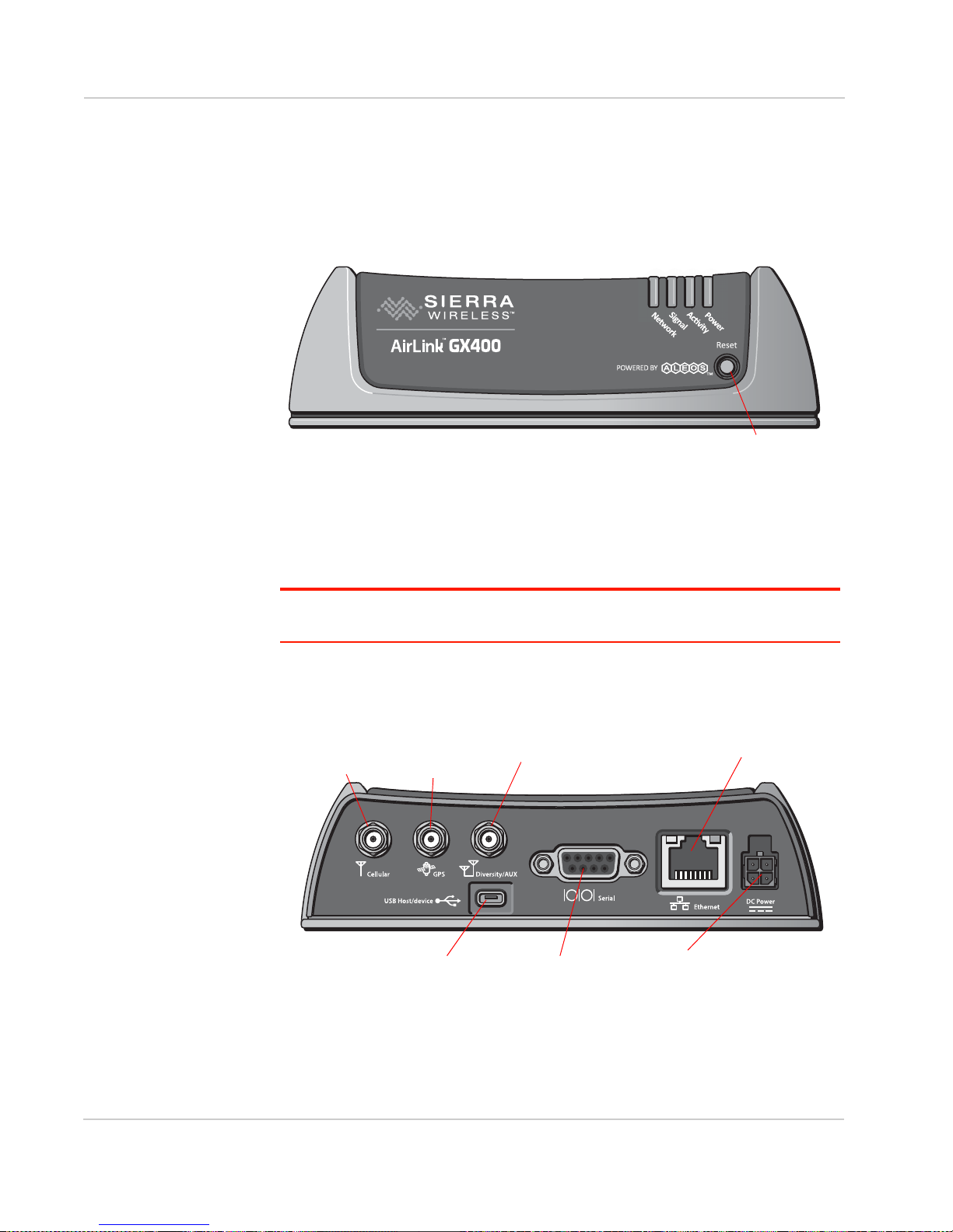
Front Panel
The front panel has the following indicators and controls:
Figure 1-1: GX Series Front Panel
•LEDs – These show the gateway’s operating status. The LEDs are described
in detail in LED Operation on page 32.
• Reset Button – Momentarily pressing and releasing this button reboots the
GX Series gateway.
Note: Holding the Reset button down for 7–10 seconds resets the GX Series gateway to
its factory default settings.
Rear Panel
The rear panel has the following connectors and controls:
Figure 1-2: GX Series Rear Panel
• Antenna Connector – This is the radio’s receive and transmit port.
(SMA connector)
10 4114008
Page 11
Introduction to the AirLink GX Series
Note: For more information on antenna connection and use, see Antenna Installation on
page 29.
• GPS Antenna Connector – This connects an optional GPS antenna to the
gateway. (SMA connector)
Note: The GPS antenna connector has a bias output and Sierra Wireless recommends
that you use an active antenna for better sensitivity.
• Diversity/AUX Antenna Connector – This connects an optional auxiliary
antenna to the gateway for backup reception capability. (SMA connector)
Note: The Diversity/AUX connector is receive only, it does not transmit.
• Ethernet Connector – This RJ-45 connector connects a standard Ethernet
cable to the gateway. This is used to connect a Windows PC to the gateway
for configuration and diagnostic purposes or attaching Ethernet equipment to
the gateway.
• Power Connector – This connects power to the gateway and provides
additional inputs and outputs for the control and monitoring of external
devices as well as triggering the low power mode. More information on its
operation and how to use it is given in Connecting a DC Power Cable on
page 34.
There are two types of optional power cables available from Sierra Wireless:
· An AC adapter (usually used for indoor, fixed applications where the
gateway runs off line power)
· DC cables (usually used in vehicles or other installations where the
gateway runs off battery power)
The gateway automatically starts when it senses qualified power on the power
connector.
• Serial Port – This 9-pin connector provides standard RS-232 communication
with a standard straight-through serial cable. It is used to communicate with
industrial machines like motors, computers or controllers or for connection to
a computer to configure the gateway with AT commands. It also supports
features like TCP PAD and UDP PAD. For more information, see Serial Port
on page 38.
•USB Port – This Micro AB connector accepts Micro A and Micro B plugs. You
can use a connected Windows PC to monitor and configure the gateway.
When connected to a PC, the USB port becomes either a:
· Virtual Ethernet port (default)
· Virtual serial port
For information on configuring the USB port, refer to the ALEOS Software
Configuration User Guide. The ALEOS User Guide and Windows drivers for
this port are available at source.sierrawireless.com.
When using the USB port:
· Use a USB 2.0 cable
· Connect directly to your computer for best throughput
Rev 8 Nov.15 11
Page 12

AirLink GX Series Hardware User Guide
X-Cards
The AirLink GX Series gateway has several optional, factory-installed, expansion
cards (X-Cards) available to add more functions to the basic gateway. They are
configurable with the ALEOS ACEmanager software and more information is
available in the ALEOS Software Configuration User Guide.
The options are:
•Wi-Fi—Adds Wi-Fi capability to the gateway using the 802.11b/g/n standard
•I/O—Has a 15-pin connector which adds to the gateway:
· One 4-wire RS-232 port
· Four analog inputs
· Four high-voltage/high-power digital I/ Os with analog readout
• Dual Ethernet—Adds two 10/100 baseT Ethernet ports
For a more complete description of each option, see X-Cards on page 39.
ALEOS Software
Note: For detailed information on all of the features in ALEOS, refer to the ALEOS
Software Configuration User Guide, available from source.sierrawireless.com.
ALEOS, the embedded core technology of the AirLink product line, provides:
• Simplified installation, operation and maintenance of any wireless solution
• An always-on, always-aware, intelligent two-way connection for mission-
critical applications
ALEOS enables:
• Reverse Telnet
• Reliable Static Routing
• SNMP
• Persistent Network Connectivity
• Over-The-Air (OTA) Upgrades
• Wireless Optimized TCP/IP
• Real-Time Notification
• Real-Time GPS Reporting
• GPS Store and Forward
• Packet Level Diagnostics
• Gateway Management & Control
Sierra Wireless has two tools for monitoring and configuring AirLink GX Series
gateways:
• ACEmanager – A web-based configuration tool for configuring a single
AirLink gateway
• AirLink Management Service (ALMS) – A cloud-based gateway
management service for monitoring and configuring fleets of AirLink
gateways
12 4114008
Page 13
Introduction to the AirLink GX Series
GX Series gateways also accept AT Commands.
ACEmanager
ACEmanager is a web-based application used to configure and monitor
GX Series gateways. ACEmanager:
• Simplifies deployment
• Provides extensive monitoring, control and management capabilities
• Enables you to configure your gateway to meet your needs
• Monitors and controls your AirLink gateway remotely and in real-time
• Is accessed through a web browser connected to the gateway
See Configuring with ACEmanager on page 47 to learn how to access
ACEmanager.
AirLink Management Service
AirLink Management Service (ALMS) is a cloud-based application, accessible
from your web browser. It provides remote monitoring and configuration for
multiple AirLink ALEOS gateways from a single computer.
ALMS features include:
• Gateway management as a service
• Advanced monitoring dashboards and alert notifications ensuring you always
know the status of your GX Series gateways
• Detailed configuration of all ALEOS parameters, including templates
providing batch updates of pre-set configurations across multiple gateways
• Over-the-air (OTA) firmware upgrades for all of your AirLink gateways with a
single operation
To connect with ALMS, see Configuring with AirLink Management Service on
page 49.
For more information on ALMS, call your AirLink reseller or visit:
www.sierrawireless.com/ALMS.
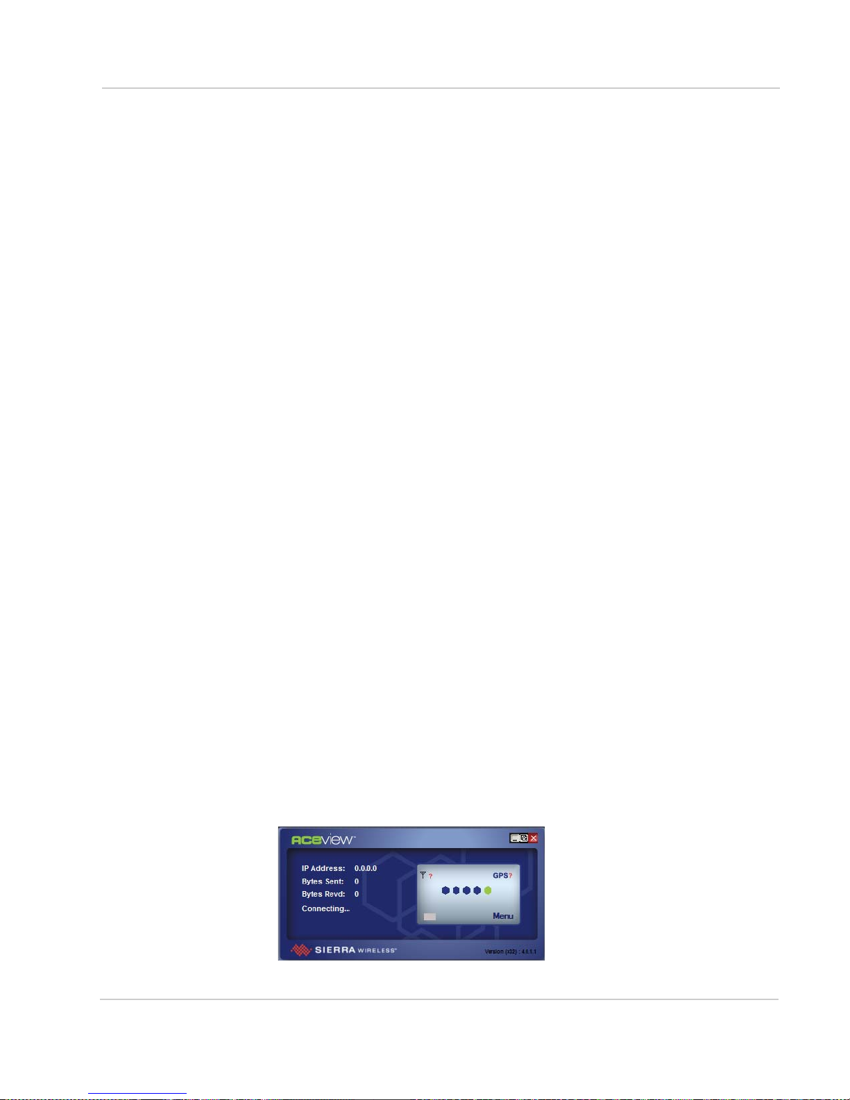
ACEview
ACEview is a Windows-based monitoring application for the PC with an easy to
read interface.You can download ACEview free of charge from
source.sierrawireless.com.
Figure 1-3: ACEview Screen
Rev 8 Nov.15 13
Page 14

AirLink GX Series Hardware User Guide
Note: ACEview requires the Microsoft .NET Framework v.2.0 and Microsoft Windows XP
or later. Obtain the Microsoft .NET Framework from Microsoft at: http://www.microsoft.com.
Accessories
Included with AirLink GX450
• DC power cable
• Mounting screws
• Quick Start Guide
Included with AirLink GX440 and GX400
• DC power cable or AC power adapter with international plug options
• Mounting screws
• Quick Start Guide
Order separately
• Ethernet cable
• DB-9 serial cable (6 ft and 25 ft lengths)
• USB cable
• Null modem cable
• LTE antenna
Ordering Information
For more information or to place an order, contact:
airlinksales@sierrawireless.com.
Warranty
The GX450 has a 3 year standard warranty, with an optional 2 year warranty
extension.
The GX400 and GX440 have a 5 year standard warranty.
14 4114008
Page 15
2: Installation and Startup
This chapter shows you how to connect, install and start the Sierra
Wireless AirLink GX Series gateway. It also describes the front panel
LEDs. Also described are the optional X-Cards available from Sierra
Wireless that add more functions to the basic gateway.
Tools and Materials Required
• If needed, a SIM card for your gateway as provided by your
mobile network operator
If you are installing a SIM card, see Installing the SIM Card on
page 16 for a list of required tools.
• Laptop computer with Ethernet cable
• SMA cellular antenna
• If used, a GPS antenna
• If used, a second SMA cellular antenna
• If used, a straight-through 9-pin connection cable for the RS-232
port
• Power cable, either the DC cable or AC cable ordered from Sierra
Wireless or your own custom-made cable
2
Note: Custom-made cables must incorporate strain relief and use the correct
type of power connector to prevent intermittent connection to the gateway.
Note: The gateway has a hardened case for use in industrial and extreme
environments. If you are installing it in these types of environments, use
cables designed and specified for use in these types of environment to avoid
cable failure.
Rev 8 Nov.15 15
Page 16

AirLink GX Series Hardware User Guide
Installing the SIM Card
All GX Series gateways except the GX400 for Sprint and Verizon networks require
a SIM card. If the SIM card has not already been installed by your Mobile Network
Operator, install the SIM card before installing or connecting any external
equipment or power to the AirLink gateway.
To install a SIM card, you need:
• SIM card for your account (provided by your Mobile Network Operator)
• 2 mm Allen (hex) wrench or a Phillips #1 screwdriver, depending on the screw
type used on the black decorative cover
• If your GX Series gateway has a Serial I/O X-Card installed:
· Small adjustable torque wrench
· 4 mm nut driver or socket that works with the torque wrench
• If your GX Series gateway has a Wi-Fi X-Card installed:
· Small adjustable torque wrench
· 8 mm socket—long enough to fit over the SMA antenna connector
The procedure for installing a SIM card varies depending on whether or not the
GX Series gateway has an X-Card installed, and if so, the type of X-Card present.
Follow the appropriate instructions for your gateway:
• Installing the SIM Card—No X-Card present on page 17
• Installing the SIM Card—Wi-Fi X-Card present on page 18
• Installing the SIM Card—I/ O X-Card present on page 21
• Installing the SIM Card—Dual Ethernet X-Card present on page 24
16 4114008
Page 17
Installation and Startup
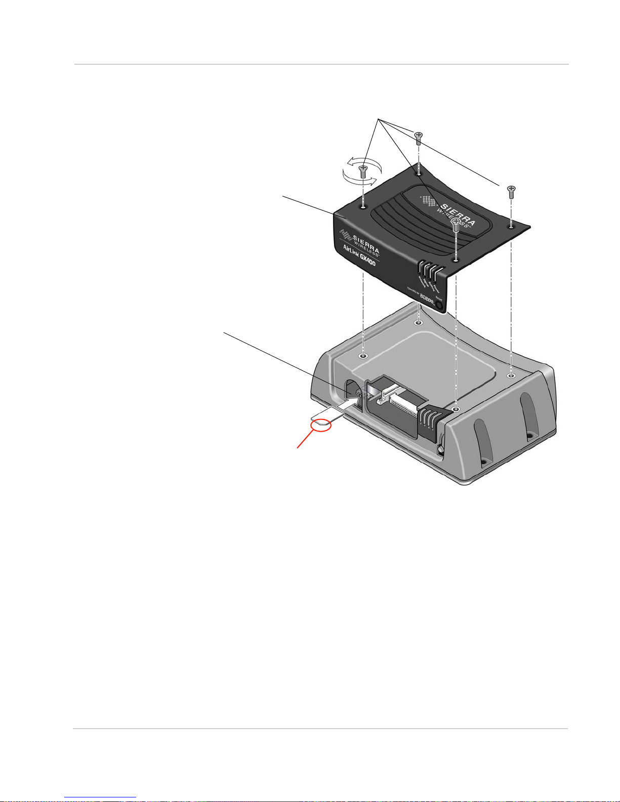
1) Remove the four screws attaching the cover.
2) Remove the cover.
3) Slide the SIM card
into the SIM card holder.
Note the direction of notched
4) Use the screws you saved in step 1 to reattach the cover. Torque the screws to 5 in-lb. (0.6 N-m).
corner of SIM card for
proper alignment.
Save the screws for reinstallation.
Installing the SIM Card—No X-Card present
Figure 2-1: SIM Card Installation, with no X-Card present
Rev 8 Nov.15 17
Page 18
AirLink GX Series Hardware User Guide
lock washer
hexagonal nut
SMA antenna connector
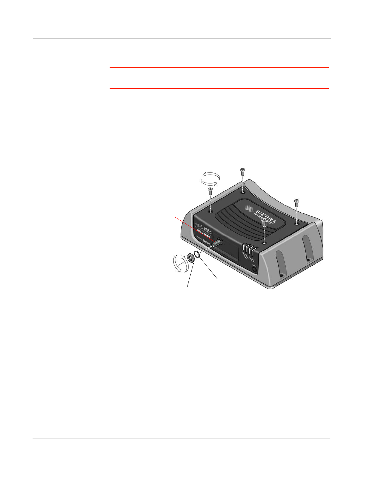
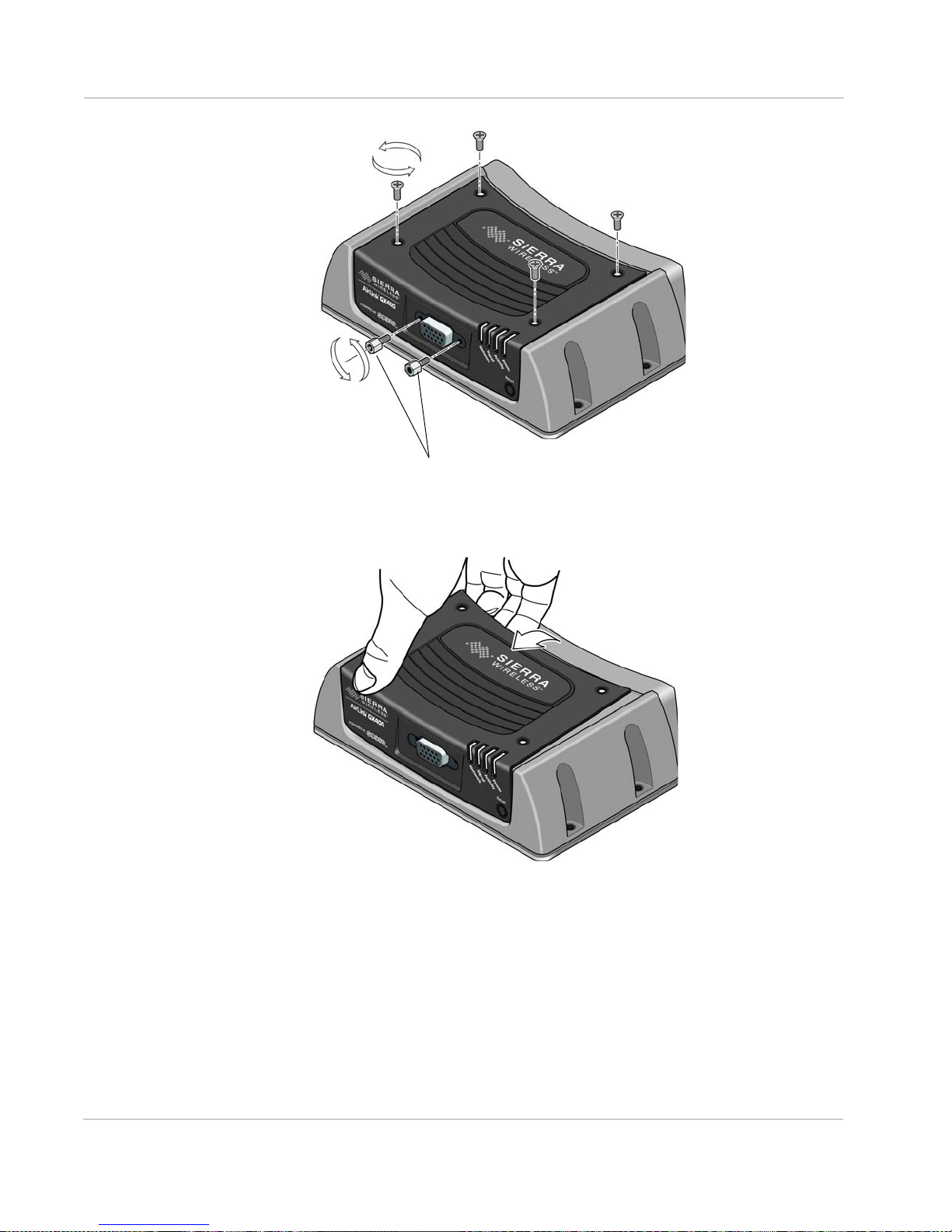
Installing the SIM Card—Wi-Fi X-Card present
Important: Failure to follow these instructions carefully may damage the X-Card and
void the warranty agreement.
To install a SIM card in a GX Series gateway with a Wi-Fi X-Card installed:
1. Unscrew the 8 mm hexagonal nut on the Wi-Fi SMA antenna connector at the
front of the gateway, using the socket and wrench. Then slide off the nut and
lock washer. Save the nut and washer. These are used again.
2. Remove the four screws used to secure the black decorative cover. Use a
2 mm Allen (hex) wrench or a Phillips #1 screwdriver, depending on the screw
type used on the black decorative cover. Save the screws for reinstallation.
Figure 2-2: Removing the screws, nut and washer (Wi-Fi X-Card installed)
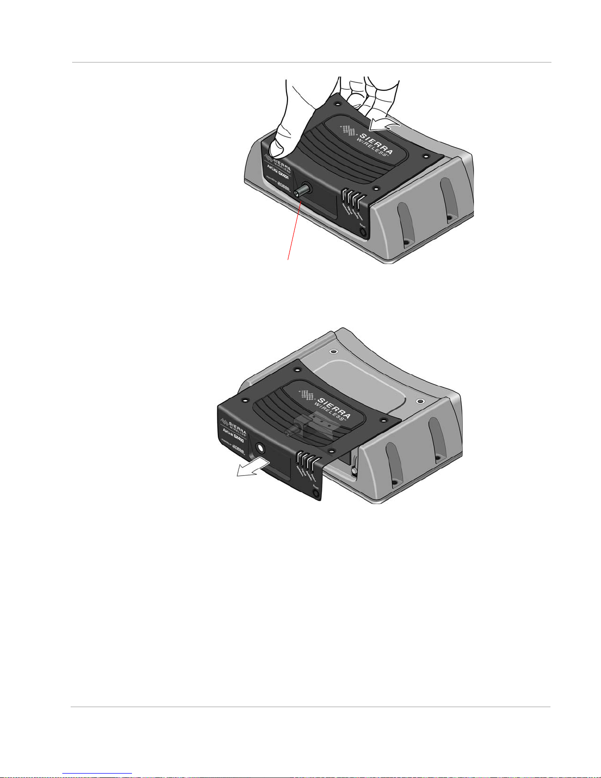
3. Gently tilt up the back of the decorative black cover and then move the cover
forward so that it slides over the Wi-Fi SMA antenna connector.
18 4114008
Page 19
Installation and Startup
Wi-Fi SMA antenna
Figure 2-3: Tilting the cover (Wi-Fi X-Card installed)
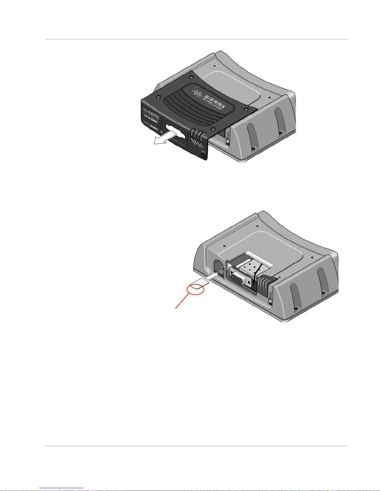
4. Continue to slide the cover horizontally until it clears the SMA antenna
connector.
5. Lift the cover to remove it completely. Save the cover. It is used later.
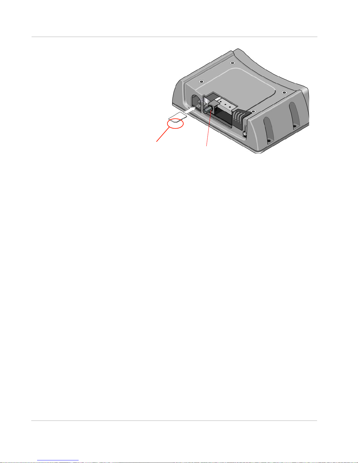
6. Insert the SIM card, with the gold contacts facing down and the notch on the
Rev 8 Nov.15 19
Figure 2-4: Removing the cover (Wi-Fi X-Card installed)
right side, as shown in the following illustration.
Page 20
AirLink GX Series Hardware User Guide
Note the direction of notched
corner of SIM card for
proper alignment.
black gasket
Figure 2-5: Inserting the SIM card (Wi-Fi X-Card installed)
7. Ensure the black gasket is in place at the base of the SMA antenna
connector.
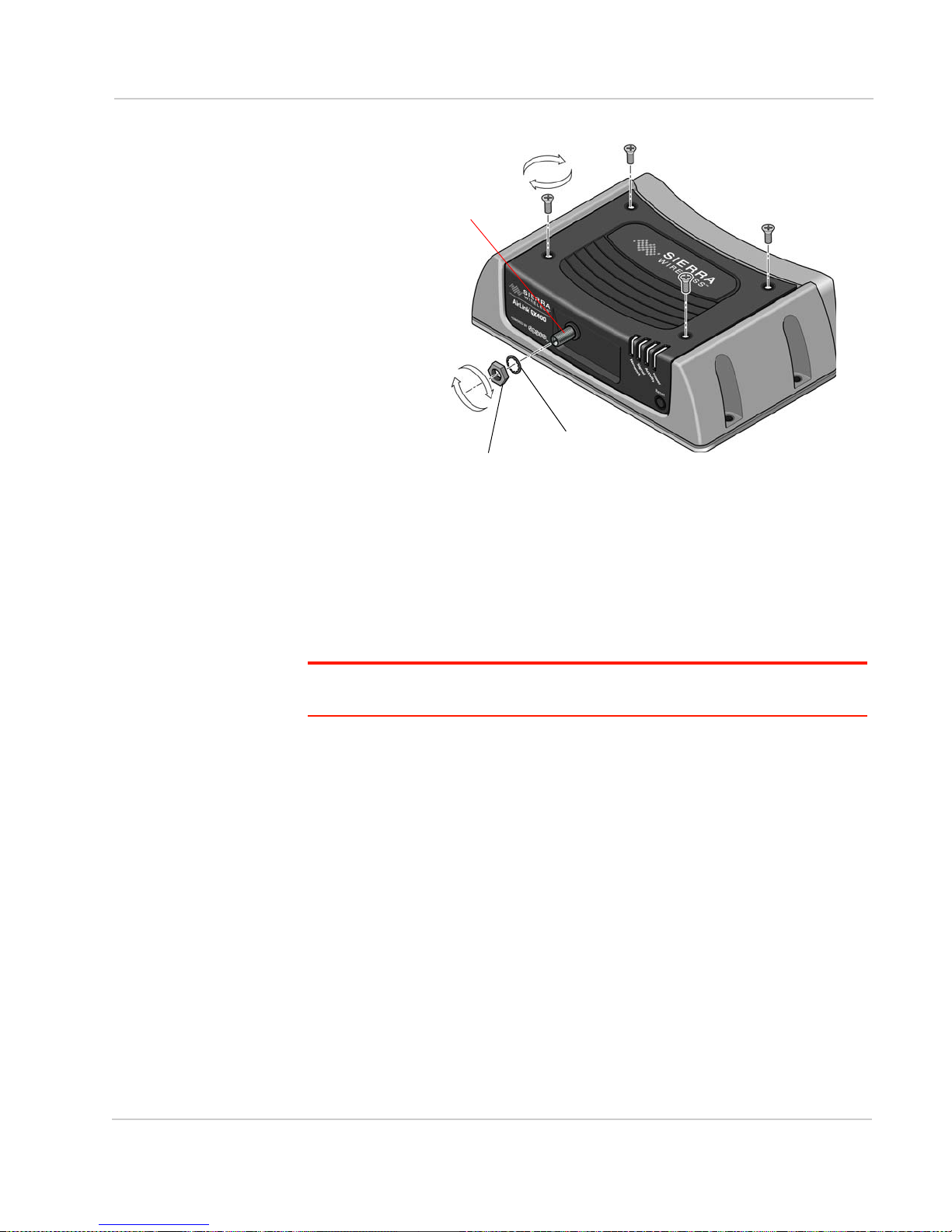
8. Re-install the decorative black cover:
a. Line up the SMA antenna connector with the hole in the cover.
b. Tilt the rear of the cover slightly to make sure the front bottom of the
cover seats in the front ridge. Slide the cover into place, and then push
the top of the cover down.
It may require some force to make sure the 4 holes in the cover line up
with the threaded holes on the top of the gateway. You may need to push
from the front as well to ensure that the holes line up properly.
9. Use the 4 screws saved in step 2 to re-attach the decorative black cover.
Torque the screws to 5 in-lb. (0.6 N-m). Ensure that the screws are tight so
that the seal underneath the decorative black cover is tight against the
gateway.
20 4114008
Page 21
Installation and Startup
lock washer
hexagonal nut
SMA antenna connector
Figure 2-6: Replacing the screws, nut, and washer (Wi-Fi X-Card installed)
10. Place the lock washer onto the SMA antenna connector and move it to the
back of the connector, so it is touching the decorative black cover.
11. Install, then tighten the nut with a 5/16" or 8 mm socket torque wrench to a
torque specification of 8in-lbs (0.9 N-m).
Installing the SIM Card—I/O X-Card present
Important: Failure to follow these instructions carefully may damage the X-Card and
void the warranty agreement.
To install a SIM card in a GX Series gateway with an I/O X-Card installed:
1. Unscrew the two 4-40 male to female hexagonal threaded standoffs (jack
screws) on either side of the serial port at the front of the gateway, using the
socket and wrench. Keep the hexagonal threaded standoffs for reinstallation.
2. Remove the four screws used to secure the black decorative cover. Use a
2 mm Allen (hex) wrench or a Phillips #1 screwdriver, depending on the screw
type used on the decorative black cover. Save the screws for reinstallation.
Rev 8 Nov.15 21
Page 22
AirLink GX Series Hardware User Guide
hexagonal threaded standoffs (jack screws)
Figure 2-7: Removing the screws and threaded standoffs (I/O X-Card installed)
3. Gently tilt up the back of the decorative black cover and then move the cover
forward so that it slides over the serial port.
Figure 2-8: Tilting the cover (I/O X-Card installed)
4. Continue to slide the cover horizontally until it clears the serial port.
22 4114008
Page 23
Installation and Startup
Note the direction of notched
corner of SIM card for
proper alignment.
Figure 2-9: Removing the cover (I/O X-Card installed)
5. Lift the cover to remove it completely. Save the cover. It is used again.
6. Insert the SIM card, with the gold contacts facing down and the notch on the
right side, as shown in the following illustration.
7. Install the decorative black cover:
8. Use the four screws you saved in step 2 to re-attach the decorative black
Rev 8 Nov.15 23
Figure 2-10: Inserting the SIM card (I/O X-Card installed)
a. Line up the serial port with the hole in the cover.
b. Tilt the rear of the cover slightly to make sure the front bottom of the
cover seats in the front ridge. Slide the cover into place, and then push
the top of the cover down.
It may require some force to make sure the 4 holes in the cover line up
with the threaded holes on the top of the unit. You may need to push from
the front as well to ensure that the holes line up properly.
cover. Torque the screws to 5 in-lb. (0.6 N-m). Ensure that the screws are
Page 24

AirLink GX Series Hardware User Guide
screw nuts
tight so that the seal underneath the decorative black cover is tight against
the gateway.
9. Re-install the screw nuts you saved in step 1 to either side of the serial port.
(Finger tight is sufficient.)
Note: The screw nuts must be re-installed to maintain the IP rating for the AirLink gateway.
Figure 2-11: Replacing the screws and nuts (I/O X-Card installed)
Installing the SIM Card—Dual Ethernet X-Card
present
Important: Failure to follow these instructions carefully may damage the X-Card and
void the warranty agreement.
To install a SIM card in a GX Series gateway with a Dual Ethernet X-Card
installed:
1. Remove the four screws used to secure the black decorative cover. Use a
2 mm Allen (hex) wrench or a Phillips #1 screwdriver, depending on the screw
type used on the black decorative cover. Save the screws for reinstallation.
24 4114008
Page 25

Installation and Startup
Figure 2-12: Removing the screws (Dual Ethernet X-Card installed)
2. Gently tilt up the back of the decorative black cover and then move the cover
forward so that it slides over the Ethernet ports, being careful not to damage
the rubber gasket.
3. Continue to slide the cover horizontally until it clears the Ethernet ports.
Rev 8 Nov.15 25
Figure 2-13: Tilting the cover (Dual Ethernet X-Card installed)
Page 26

AirLink GX Series Hardware User Guide
Note the direction of notched
corner of SIM card for
proper alignment.
Figure 2-14: Removing the cover (Dual Ethernet X-Card installed)
4. Lift the cover to remove it completely. Save the cover. It is used again.
5. Insert the SIM card, with the gold contacts facing down and the notch on the
right side, as shown in the following illustration.
Figure 2-15: Inserting the SIM card (Dual Ethernet X-Card installed)
6. Install the decorative black cover:
a. Line up the Ethernet ports with the hole in the cover.
b. Tilt the rear of the cover slightly to make sure the front bottom of the
26 4114008
cover seats in the front ridge. Slide the cover into place, and then push
the top of the cover down. Ensure that the black gasket around the
Ethernet ports is snug, with no gaps and the gasket is not folded in on
itself.
It may require some force to make sure the 4 holes in the cover line up
with the threaded holes on the top of the unit. You may need to push from
the front as well to ensure that the holes line up properly.
Page 27

Installation and Startup
black gasket around
the Ethernet ports
7. Use the 4 screws saved in step 1 to re-attach the decorative black cover.
Torque the screws to 5 in-lb. (0.6 N-m). Ensure that the screws are tight so
that the seal underneath the decorative black cover is tight against the
gateway.
Figure 2-16: Replacing the screws (Dual Ethernet X-Card installed)
Mounting the GX Series
Warning: This gateway is not intended for use close to the human body. Antennas
should be at least 8 inches (20 cm) away from the operator.
Note: The gateway has a hardened case for use in industrial and extreme environments. If
you are installing it in these types of environments, use cables designed and specified for
use in these types of environments to avoid cable failure.
Mount the gateway where:
• There is easy access to the cables
• Cables are not bent, constricted, close to high amperages or exposed to
extreme temperatures
• Cables are secured to ensure reliable connections
• The front panel LEDs are easily visible
• There is adequate airflow
Rev 8 Nov.15 27
Page 28

AirLink GX Series Hardware User Guide
62.5 mm
(2.5 in.)
22.5 mm
(0.9 in.)
5.2 mm (0.2 in.)
136 mm (5.4 in.)
Mounting holes
diameter: 5.3 mm (0.2 in.)
0
0
• It is kept free from direct exposure to the elements, such as sun, rain, dust,
etc.
In addition to the four mounting holes on the side of the gateway’s body, there are
four holes on the bottom plate to attach the gateway to a mounting surface.
Figure 2-17: GX Series Bottom Plate and Mounting Holes
Grounding the GX Series Gateway Chassis
For DC installations (with a fixed “system” ground reference), Sierra Wireless
recommends always grounding the GX chassis or the mounting bracket to the
system ground reference. To ensure a good grounding reference, use a short wire
with a gauge of 18 AWG or larger connected to one of the mounting holes with
the screws and lock washers provided in the supplied mounting kit.
Vehicle Mounting
The AirLink GX Series gateway must be installed by qualified personnel in
accordance with the vehicle manufacturer’s specifications.
When installing the gateway in a vehicle:
• Keep it out of direct exposure to the weather (sun, rain, etc.). The best
locations are in places like a car trunk or in a container behind the seats.
• Place it where it will not be bumped or come into contact with people, cargo,
tools, equipment, etc.
For information on connecting the power, see Connecting a DC Power Cable on
page 34.
28 4114008
Page 29

Installation and Startup
Antenna Installation
Inadequate antenna separation between the transmit and diversity antennas
creates unwanted interactions. This can cause reductions in:
• Antenna efficiency
• Transmit power
• Receiver sensitivity
• Data throughput
• Radio front-end life span
Antenna Separation Recommendations
• The antennas should be separated so that there is at least 10 dB isolation
over the entire operating frequency range.
• The separation should be at least 1/4 wavelength (), but preferably
1/2 wavelength or greater of the lowest operating frequency. See Ta bl e 2 - 1 for
specific recommendations, based on your network service type and
frequency.
Note: The values in the table are approximate antenna separation values for monopole or
dipole type antennas.
Table 2-1: Recommended Antenna Separation
Service Frequency
LTE 700 428 214 107
LTE 800 375 187 94
LTE 900 333 167 83
LTE 1800 167 83 42
LTE 2100 143 71 36
LTE 2600 115 58 29
WCDMA 850 353 176 88
WCDMA 900 333 167 83
WCDMA 1900 158 79 39
WCDMA 2100 143 71 36
CDMA/EV-DO 800 375 187 94
(MHz)
Wavelength (
(mm)
Best Antenna
Separation (mm)
(1/2
Good Antenna
Separation (mm)
(1/4
Rev 8 Nov.15 29
CDMA/EV-DO 1900 158 79 39
GSM/GPRS/
EDGE
850 353 176 88
Page 30

AirLink GX Series Hardware User Guide
Table 2-1: Recommended Antenna Separation
Service Frequency
GSM/GPRS/
(MHz)
900 333 167 83
Wavelength (
(mm)
Best Antenna
Separation (mm)
(1/2
Good Antenna
Separation (mm)
(1/4
EDGE
GSM/GPRS/
1800 167 83 42
EDGE
GSM/GPRS/
1900 158 79 39
EDGE
Table 2-2: Separation Examples for Specific Mobile Network Operator Bands
Service Band Mobile Network
Operator
LTE 13 Verizon US 746 401.8665657 201 100
LTE 17 AT&T US 704 425.8415597 213 106
LTE 4 Bell/Rogers/Telus Canada 1710 175.3172269 88 44
Country Min
Frequency
(MHz)
Wavelength (
(mm)
Best Antenna
Separation (mm)
(1/2
Good Antenna
Separation (mm)
(1/4
Antenna Recommendations
Note: Do not remove the diversity antenna. The diversity antenna helps the gateway
achieve the maximum network coverage. The gateway works without one installed, but
with reduced network coverage.
Note: If the antennas are located far away from the gateway, keep the cables as short as
possible to prevent the loss of antenna gain.
Warning: The antenna should not exceed the maximum gain specified in Maximum
Antenna Gain (Gain D'antenne Maximal) on page 69. In more complex installations (such
as those requiring long lengths of cable and/or multiple connections), you must follow the
maximum dBi gain guidelines specified by the radio communications regulations of the
Federal Communications Commission (FCC) or Industry Canada or your country’s
regulatory body (if used outside the US). Also see Important Information for North
American Users on Radiation Exposure on page 68 for more information.
30 4114008
Page 31

Installation and Startup
GPS antenna
Cellular antenna
AirLink GX gateway
(not to scale)
Mounting the GPS Antenna
Mount the antenna where it has a good view of the sky such as on the roof, the
dashboard or the rear panel. It should see at least 90
Figure 2-18: Mounting the GPS Antenna
⁰ of the sky.
Connecting the GX Series Gateway
Note: Route cables so that they are protected from damage and will not be snagged or
pulled on. There should be no binding or sharp corners in the cable routing. Excess cabling
should be bundled and tied off. Make sure the cables are secured so their weight will not
loosen the connector from the gateway over time.
1. Connect the RF antenna to the antenna connector.
2. If used, connect the GPS antenna to the GPS antenna connector.
3. If used, connect an RF antenna to the Diversity/AUX antenna connector.
4. Attach a laptop to the gateway with the Ethernet cable.
5. If used, attach a gateway or computer to the RS-232 port and/or the USB
Note: Before proceeding, turn off the power going to the gateway.
6. Connect the power cable to the gateway, and if used, to the external devices
Note: For details about the power connector, see Connecting a DC Power Cable on
page 34. The battery connector cable should be no longer than 10 feet (3 meters).
port.
to be controlled/monitored.
Rev 8 Nov.15 31
Page 32

AirLink GX Series Hardware User Guide
7. Turn on the power.
The gateway starts automatically as soon as it receives power. If it fails to
start, ensure that the:
· Power connector is plugged in
· Power cable is connected to power (line or battery power)
· Power is turned on or that the battery is fully charged
· Ignition Sense (pin 3) is connected to the battery or power source (see
Connecting a DC Power Cable on page 34 for details)
For information on configuring the GX Series gateway, see Configuring AirLink
GX Series gateways on page 47.
LED Operation
Power-up and Reboot
On power-up or reboot, all LEDs turn red, then amber, then green. They then go
through a blinking sequence that ends with the Power LED green and all the other
LEDs off. Once the other LEDs resume their normal operating behavior, the
reboot is complete.
To reboot the gateway:
• In ACEmanager, click the Reboot button at the top right of the screen.
• Press and release the Reset button on the gateway (see Front Panel on
page 10). Do not hold the button down for more than a few seconds. (If you
hold it for 7– 10 seconds, the gateway resets to factory default settings.)
LED Behavior
Table 2-3: LED Behavior
LED Color/Pattern Description
Power Off No power or input voltage ≥36 VDC or ≤9 VDC
Solid Green Gateway is connected to nominal power and is operating normally.
Flashing Amber/Green Gateway has a GPS fix
Solid Amber Gateway is entering low power mode or system low level boot.
Solid Red Gateway is not operational (failure or in low power mode).
Signal Solid Green Good signal
Solid Amber Marginal signal (-100 dBm < RSSI < -85 dBm)
Solid Red Poor signal (-110 dBm ≤ RSSI ≤ -100 dBm)
(RSSI
≥ -85 dBm)
Flashing Red No signal (RSSI < -110 dBm)
32 4114008
Page 33

Installation and Startup
Activity
Connection speed
Table 2-3: LED Behavior
LED Color/Pattern Description
Network Solid Green Network Ready — (LTE service available for GX440)
Flashing Amber/Green Network Ready — (No L TE service available for GX440)
Activity
(ALEOS
4.3.6 or
earlier)
Activity
(ALEOS
4.4.0 or
later)
Flashing Green
(3 sec. on/1 sec. off)
Flashing Green
(1.0 sec. on/0.5 sec. off)
Flashing Amber/Green/Off Network Ready—Roaming (No LTE service for GX440)
Flashing Amber No Service
Solid Amber Connecting to the network
Flashing Red Authentication/Negotiation failed (EV-DO only)
Solid Red Link Down
Off Normal operation
Flashing Green Traffic is being transmitted or received over the WAN interface.
Off Normal operation
Flashing Green Traffic is being transmitted or received over the WAN interface.
Flashing Red Traffic is being transmitted or received over the serial port. (This
Network Ready—WAN over Wi-Fi (gateway in Wi-Fi client mode)
Network Ready—Roaming (LTE service available for GX440)
No cellular network is present, no network coverage at current
location, or the gateway is in radio passthru mode
behavior only appears if the AirLink GX Series gateway is configured
to display it. Refer to the ALEOS Software Configuration Guide for
details.)
Flashing Amber Traffic is being transmitted or received over both the WAN interface
and the serial port. (This behavior only appears if the AirLink GX
Series gateway is configured to display it. Refer to the ALEOS
Software Configuration Guide for details.)
Ethernet LEDs
Figure 2-19: Ethernet LEDs
Rev 8 Nov.15 33
Page 34

AirLink GX Series Hardware User Guide
The Ethernet connector has two LEDs that indicate speed and activity. When
looking into the connector:
• Activity— The right LED is solid amber when a link is detected (the cable is
plugged in) and blinks when there is activity.
• Connection Speed— The left LED is green to indicate a 100 Mbps connection
and orange to indicate a 10 Mbps connection. It is off when no cable is
connected.
Power-up and Reboot
On power-up or reboot, the LEDs go through a booting sequence. When the boot
is complete, the Power and Network LEDs should be green, signifying that the
power is on, the GX Series gateway is connected to the wireless network, and
there is a good signal. See Ta bl e 2 -3 on page 32 for detailed LED operation.
To reboot the GX Series gateway, either:
• In ACEmanager, click the Reboot button at the top right of the screen.
Or
• Press and release the Reset button on the GX Series gateway (see Front
Panel on page 10).
Reset to factory default settings
To reset the gateway to the factory default settings, either:
• Press and hold the Reset button until all the LEDs turn amber-green (about
7–10 seconds). See Front Panel on page 10.
Or
• In ACEmanager, go to Admin > Advanced and click the Reset to Factory
Default button. For details, refer to the ALEOS Software Configuration User
Guide.
The gateway reboots. Once the reboot is complete and the LEDs resume their
normal operating behavior, the reset is complete.
Connecting a DC Power Cable
The GX Series gateway has a four-pin power connector that has:
• Two pins connecting DC voltage to the gateway
• Two pins providing additional monitoring and control functions
34 4114008
Page 35

Installation and Startup
Fusing
For DC installations, Sierra Wireless recommends fusing the power input using a
2.0 A fast-acting fuse. Install the fuse on the positive line, as shown in Figure 2-20
on page 36. For vehicle installations, use an automotive fuse.
Power Supply Conditioning
For automotive applications, the supply voltage may momentarily drop below
9.0 V during engine cranking, causing the GX Series gateway to reboot. If this
happens, the GX gateway restarts automatically and is ready for use once the
reboot is complete. If your application requires the GX gateway to continue
operating during engine cranking, add external power conditioning circuits to
ensure the supply voltage does not drop below the rated value (9.0 V)
Power Connector on the GX Series Gateway
If you are using the DC power cable to connect the GX Series gateway to a power
source:
• Pin 1—Use the red wire in the DC cable to connect Pin 1 to the power
source. Include a 2.0 A fast-acting fuse in the input power line. Sierra
Wireless recommends using a continuous (unswitched) DC power source.
For installations that require the device to be turned on/ off, Sierra Wireless
recommends using the Ignition Sense (Pin 3) input for this purpose.
• Pin 2—Use the black wire in the DC cable to connect Pin 2 to ground. See
also Grounding the GX Series Gateway Chassis on page 28.
• Pin 3 (Ignition Sense)— Sierra Wireless recommends always using the
Ignition Sense wire to turn the gateway off. It should not be turned off by
disconnecting the power.
For installations where the GX Series gateway is turned on/off, use the white
wire in the DC cable to connect Pin 3 to:
· A vehicle ignition for turning the gateway on with the ignition is on
· A low voltage monitor for turning the gateway off when the supply voltage
drops below a defined level.
For installations where the GX Series gateway is permanently on (never
turned on / off), connect the white wire to the red wire.
Pin 3 can be used as the trigger for the low power mode. For more information, refer to the ALEOS Software Configuration User Guide (Services chapter). If desired, you can also configure the GX Series gateway to notify you
when it goes into Low Power mode. For details, refer the ALEOS Software
Configuration User Guide (Events Reporting chapter).
Note: Sierra Wireless strongly recommends that you use an unswitched VCC, with Pin 3
(white wire on DC cable) connected to the ignition (if you want the GX on when the ignition
is on) or connected to a low voltage monitor (if you want the GX to turn off when the
voltage drops below a defined level) See Figure 2-20 on page 36. This is particularly
important for when the input power supply is not constant, such as vehicle installations.
Rev 8 Nov.15 35
Page 36

AirLink GX Series Hardware User Guide
GPI/O
Battery
-
+
2.0 A fast-acting
Ignition switch
fuse
Pin 4
Connect to switch, relay
or external device
Pin 3
Pin 2
Ground
Ignition Sense
Pin 1
Power
Optional:
Green
Red
Black
White
GX Series gateway
• Pin 4 (General Purpose I/O) (Optional)— Use the green wire in the DC cable
to connect Pin 4 to a switch or relay on an external device you want to
monitor. For more details, see page 37.
See Figure 2-20 and Ta bl e 2- 4 .
Table 2-4: Power Connector Pin and DC cable Wires
Pin Name Associated DC
1 Power Red Main power supply for device PWR
2 GND Black Main device ground PWR
3 IGN Sense White Ignition Sense: Connected to the vehicle ignition or an external
4 GPIO Green User configurable digital input/output or analog voltage sensing
Cable Wire Color
Figure 2-20: DC power cable connections (Colors indicate DC cable wire colors.)
Description Type
switch, for example on a low voltage shutdown. When the GX
gateway is connected to a low voltage shutdown, the GX
gateway is off when this pin is either open-circuit or grounded,
and on when this pin is connected to power.
Note: If you do not connect pin 3 to the ignition, you MUST
connect it to the positive terminal of your power supply or
battery. If you are using a Sierra Wireless AC adapter, the
connection is inside the cable.
input. Connect to switch, relay or external device. Maximum
rating is 30 V, 150 mA. For more information, see Pin 4 (General
Purpose I/O) on page 37 and the ALEOS Software Configuration
User Guide.
I
I/O
36 4114008
Page 37

Installation and Startup
3.3 V
Contact closed
Digital 0
0 VDC to 1.2 VDC
Contact open
Digital 1
2.2 VDC to 30 VDC
Contact
Ground
51 k
internal
pull up
I/O Circuit
Examples: Door opening/closing, valve opening/closing, ignition on/off, tow bar up/down,
empty/full container.
AirLink GX gateway
Pin 4 (General Purpose I/O)
This pin is a digital input/output (green wire on DC cable).
Pin 4 either:
• Monitors digital inputs and outputs
• Drives a relay
It has a maximum rating of 30 V and 50 mA sink current. The pin is user
programmed. For information on configuring Pin 4 (Digital Input/ Relay Output 1 in
ACEmanager) refer to the ALEOS Software Configuration User Guide.
One way to use pin 4 is with events reporting. In ACEmanager you:
1. Create an Event.
This triggers the gateway to act when it sees a specific input. For example,
you can tell the gateway to do something when the Pin 4 state (Digital Input/
Relay Output 1 in ACEmanager) changes. This could be when a door is
opened, activating a switch attached to it.
2. Specify an Action.
These are instructions the gateway performs when it sees an event. For
example, an email could be sent to security, saying the door is open, giving
the time, location and other information.
There are several typical uses for Pin 4:
• As a digital input, it monitors a switch, using its opening or closing to record
events or monitoring external voltages of up to 30 VDC. For example, you
could use it to measure the voltage on a 24 VDC light bulb and have the
gateway react when it turns on.
When the switch, or input voltage is:
· Open (2.2 VDC to 30 VDC) – It is read as a digital input =1
· Closed (0 to 1.2 VDC) – It is read as a digital input = 0
Figure 2-21: Digital Input Operation
Rev 8 Nov.15 37
Page 38

AirLink GX Series Hardware User Guide
3.3 V
51 k
internal
pull up
Voltage supply
CL+
CL-
COM
NC
NO
I/O Circuit
Pin 4 is normally at 3.3 V,
but is pulled low
External Solenoid/Relay Circuit
(Exact voltages and configuration
depend on the actual system design.)
when activated.
AirLink GX gateway
Flyback diode
• As a digital output, it can trigger an alarm, siren, door lock or open a valve or
a switch. Pin 4 is an open collector transistor output normally at 3.3 VDC.
When triggered, it is pulled to low.
Figure 2-22: Digital Output Operation
Note: Some solenoids/relays include a flyback diode built into the unit. For those that do
not, Sierra Wireless recommends a flyback diode with a voltage rating at least double the
relay voltage and a current rating at least double the relay ON current to avoid damage to
the GX input. A common 1N4007 will work for most applications. See Table 2-7 on
page 42.
The initial state of the digital output when the gateway is rebooted is configurable
in ACEmanager.
Serial Port
You can connect the GX Series gateway’s 9-pin serial connector directly to most
computers or other devices with a standard straight-through cable. This connector
is used for gateway configuration and debugging.
This connector complies with the EIA RS-232D specification for DCE equipment.
The output driver levels swing from -7 VDC to +7 VDC with normal loading.
Note: If you have a DCE device, you need to use a null modem cable.
38 4114008
Page 39

Installation and Startup
5
987 6
43 21
Figure 2-23: 9-Pin Serial Connector Diagram
Table 2-5: Serial Connector Pin-out
Name Pin Description Type
DCD 1 Data Carrier Detect OUT
TXD 2 Transmit Data OUT
RXD 3 Receive Data IN
DTR 4 Data Terminal Ready IN
GND 5 Mai n GND. Connected internally to BOARD_GND GND
DSR 6 Data Set Ready OUT
RTS 7 Ready To Send IN
CTS 8 Clear To Send OUT
RI 9 Ring Indicator OUT
X-Cards
The AirLink GX Series has several optional, factory-installed, expansion cards
(X-Cards) available to add more functions to the basic gateway. They are
configurable with ACEmanager and more information is available in the ALEOS
Software Configuration User Guide, which is available for downloading from the
Sierra Wireless web site.
The available X-Cards are:
• Wi-Fi
• I/O
• Dual Ethernet
If you have an X-Card installed in your gateway, its type and status is shown on
the ACEmanager home page (Status > Home).
Rev 8 Nov.15 39
Page 40

AirLink GX Series Hardware User Guide
54321
10 9 8 7 6
1112131415
Wi-Fi X-Card
This card adds Wi-Fi capacity to the gateway using the 802.11b/g/n standard. It
has the following modes:
• Client Mode where a GX gateway uses a Wi-Fi client connection to connect to
an access point, rather than acting as an access point (AP)
• Access Point Mode where the gateway acts as an AP
• Both (AP + Client Mode) where the gateway can act as an AP and also use a
Wi-Fi Client connection to connect to an AP
The GX Series gateway connects as a client to a configured AP whenever the
AP is available. When the AP is not available, it connects to a 3G network and
acts as an AP to W-Fi clients connected to the GX.
Note: The Wi-Fi X-card requires the use of an antenna with a male RP-SMA connector.
See the ALEOS Software Configuration User Guide for details on Wi-Fi
configuration and use.
I/O X-Card
This card uses a 15-pin connector to add to the basic gateway:
• One additional RS-232 communication port
• Four additional digital I/O pins
• Four analog voltage sensing pins
• Optional 2 meter I/ O X-Card breakout cable (To order, contact your
distributor.)
Maximum data rate for the RS-232 interface on the I/O X-Card is 115.2 kbps.
See the ALEOS Software Configuration User Guide for details on I/O set up and
use.
I/O X-Card 15-Pin Connector Description
Figure 2-24: I/O X-Card 15-pin Connector Pin Diagram
40 4114008
Note: For better performance, signal pins on the I/O X-Card should be referenced to the
ground pin on the I/O X-Card (pin 10).
Page 41

Installation and Startup
An optional 2-meter 15-pin I/ O breakout cable (pn 2000424) for use with the I/O
X-card is available from distributors.
Table 2-6: I/O 15-Pin Connector Pin Description
Pin Name Description Wire color
(on optional I/O X-Card breakout
cable)
1 TXD Transmit Data White/Black
2 CTS Clear to Send Red/Black
3 DIO[2] Digital I/O 2 Green/Black
4 DIO[4] Digital I/O 4 Orange/Black
5 RXD Receive Data Blue/Black
6 RTS Request to Send Blue
7 AIN[2] Analog Input 2 Green
8 AIN[4] Analog Input 4 Red
9 Reserved for future use Black
10 GND Ground White
11 DIO[3] Digital I/O 3 Orange
12 DIO[5] Digital I/O 5 Blue/White
13 Reserved for future use Green/White
14 AIN[1] Analog Input 1 Red/White
15 AIN[3] Analog Input 3 Black/White
Shield Cable Shield
This is not a VGA connector
Note: Digital Input 1 in ACEmanager is reserved for Pin 4 on the power connector.
To check the current digital input values, in ACEmanager:
1. Go to I/O > Current State.
Digital I/O Interface
There are four digital I/O pins on the high density DB15 connector. Typical
applications are:
• Input—source is a dry switch contact to ground
• Output—to drive a relay coil to ground
• Analog—to detect voltage levels in input or output mode
Pins include a 51 k
Rev 8 Nov.15 41
pull up to 2.8 VDC.
Page 42

AirLink GX Series Hardware User Guide
2.8 V
Contact closed
Digital 0
0 VDC to 1.2 VDC
Contact open
Digital 1
2.2 VDC to 30 VDC
Contact
Ground
51 k
internal
pull up
I/O Circuit
Examples: Door opening/closing, valve opening/closing, ignition on/off, tow bar up/down,
empty/full container.
AirLink GX gateway
2.8 V
51 k
internal
pull up
Voltage supply
CL+
CL-
COM
NC
NO
I/O Circuit
Pins 3, 4, 11, and 12 are normally at 2.8 V,
External Relay Circuit
(Exact voltages and configuration
depend on the actual system design.)
AirLink GX gateway
Flyback diode
but pulled low when activated
Figure 2-25: Digital Input Operation
Figure 2-26: Digital Output Operation
Table 2-7: Digital I/O
Pins Name Specification Min Typical Max Units
3
4
11
12
42 4114008
DIO[2...5]
(as input)
DIO[2...5]
(as output)
Input low state voltage
(At or below this voltage, relay reads as low)
Input high state voltage range
(At or above this voltage, relay reads as high)
Input leakage current at 5 V — 0.05 — mA
Input leakage current at 12 V — 1.8 — mA
Input leakage current at 24 V — 5.5 — mA
Open drain drive to ground — 100 — mA
Maximum open circuit voltage applied — — 30 V
— — 1.2 V
2.2 — — V
Page 43

Installation and Startup
I/O X-Card Digital I/O Input Pins
Pins 3, 4, 11 and 12 are programmed in ACEmanager to monitor inputs, respond
to certain types of events or trigger a digital output. They behave exactly like the
Digital I/O (pin 4) on the power connector as described in Connecting a DC Power
Cable on page 34.
Note: Digital Input 1 in ACEmanager is reserved for Pin 4 on the power connector.
Pins 3, 4, 11 and 12 (Digital inputs 2 to 5) have a voltage of 3.3 VDC when set to
high in ACEmanager. A voltage on the pins of:
• 2.2 VDC to 30 VDC = logic 1
• 0 VDC to 1.3 VDC= logic 0
I/O X-Card Analog Voltage Input Pins
Pins 7, 8, 14 and 15 are the analog voltage sensing pins configured in
ACEmanager. Analog inputs monitor voltage changes in small increments. This
allows you to monitor equipment that reports status as an analog voltage. You can
use volts as the units reported or you can use the ACEmanager I/O Configuration
screen to convert voltage to the desired units of measurement. You can also use
the Event Reporting feature in ACEmanager to configure reports to be sent when
an analog threshold is crossed. For more information, refer to the ALEOS
Software Configuration User Guide.
The pins have a maximum rating of 30 V, 200 µA.
Table 2-8: I/O X-Card Analog Voltage Input Pins
Pins Name Specification Parameter Min Typical Max Units
7
8
14
15
AIN[1...4] Voltage range VADC 0 — 30 V
Input leakage current — — 200 µA
Input capacitance CIN — 30 — pF
Error 0 2.5 5 %
These pins detect inputs of 0–30 VDC across the pins to ground. When used with
a sensor to transform values into voltages, the pins can monitor measurements
like temperatures, pressures or the volume of liquid in a container. ACEmanager
can transform these voltages into meaningful values. In ACEmanager, events
reporting tells the gateway to perform an action when a specified voltage is
detected.
Rev 8 Nov.15 43
Page 44

AirLink GX Series Hardware User Guide
Level Full
Sensor output
voltage = 20 V
Level Almost empty
Sensor output
voltage = 5 V
Storage
Tank
Storage tank
level sensor
AirLink gateway configured in ACEmanager
to send an email when storage tank is
almost empty (5 V on pin)
Analog voltage input
available on connector
pins 7, 8, 14, 15
Note: Pins have a maximum rating
of 30 V, 200 µA
Figure 2-27: I/O X-Card Analog Voltage Input Operation
I/O X-Card RS-232 Port
Four pins on the high density DB15 support a 4-wire RS-232 interface. The
interface also supports features like AT, TCP PAD and UDP PAD.
Table 2-9: I/O X-Card RS-232 Port
Pins Name Specification Parameter Min Typical Max Units
1
2
5
6
TXD
CTS
RXD
RTS
Output low state voltage range VOL -5.0 -7.0 — V
Output high state voltage range VOH +5.0 +7.0 — V
Short circuit current 1 short — ±35 ±70 mA
Leakage current 1 leak — ±0.1 ±10 µA
Input low state voltage range VIL -5.0 — -20 V
Input high state voltage range VIH +5.0 — +20 V
Input resistance R in 3 5 7 k
Note: There is no connection for RI, DCD, DTR or DSR. These are available on the DB-9
serial port. See Serial Port on page 38.
Dual Ethernet X-Card
This card adds two RJ-45 Ethernet ports to the gateway for a total of three. The
two Ethernet ports on the X-Card are bridged with the gateway’s main Ethernet
port, automatically becoming part of the same subnet.
The main Ethernet port on the rear panel is a high performance Ethernet port with
data rates up to 100 Mbps.
The Dual Ethernet X-Card provides additional Ethernet ports for applications
requiring lower throughput (in the range of 8–9 Mbps, or less if both ports are
44 4114008
being used).
Page 45

Installation and Startup
For example, the Ethernet ports on the Dual Ethernet X-Card are ideal for
applications that run on IP or other protocols that run on top of IP such as TCP
and UDP.
Other suggested applications include:
• Modbus applications
• Low Resolution MMS (MultiMediaStreaming using mms://) applications
• Message Queuing Telemetry Transport (MQTT) applications
• Low Resolution Video surveillance applications
Configuring Dual Ethernet X-Card Ports
When your GX Series gateway has a Dual Ethernet X-Card installed, you can
configure the additional Ethernet ports as Ethernet 2 and Ethernet 3 on the
ACEmanager LAN > Ethernet screen. Information about the Ethernet ports
appears on the Status > LAN and the Status > About screens. The LAN IP
packets sent and received fields on the Status > LAN screen show the cumulative
totals for all LAN interfaces.
Rev 8 Nov.15 45
Page 46

AirLink GX Series Hardware User Guide
46 4114008
Page 47

3: Configuring AirLink GX Series
gateways
This chapter shows you how to communicate with and configure the
Sierra Wireless AirLink GX Series gateway.
Connection Ports
You can connect to the gateway’s:
• USB port (Micro AB)
• Ethernet port (RJ-45)
• Serial port (9-pin RS-232)
USB Port
The USB port can be either a:
• Virtual Ethernet port
• Virtual serial port
Drivers must be installed on the PC for it to work in either mode. They
are available for download at source.sierrawireless.com.
We recommend you:
• Use a USB 2.0 cable
• Connect directly to your computer for best throughput
3
Configuring with ACEmanager
After the initial power up:
1. In the laptop connected to the gateway, open a web browser.
2. In the browser’s address bar, enter:
http://192.168.13.31:9191
Note: It may take a minute or two for the gateway to respond after the first
power up.
The ACEmanager login screen appears.
3. The default user name, user, is already entered. Enter the default
password,12345.
Rev 8 Nov.15 47
Page 48

AirLink GX Series Hardware User Guide
Figure 3-1: ACEmanager Login Screen
The ACEmanager Status > Home page appears1.
Figure 3-2: ACEmanager Status > Home page
4. If the gateway does not automatically connect to the network:
a. Check the Network State field. It should say “Network Ready”. If it says
b. Check the Signal Strength field. It should be greater than -100.
1. The appearance of the screen varies depending on the version of ALEOS in stalled
48 4114008
“No SIM or Unexpected SIM”, check that the correct SIM card is inserted.
(See Installing the SIM Card on page 16.)
on the gateway and the type of network the gateway is connected to.
Page 49

Configuring AirLink GX Series gateways
c. Check the APN on the WAN/Cellular tab. If an error message appears in
this field, contact your Mobile Network Operator. They may need to
provide you with an APN to enter in the User Entered APN field.
Figure 3-3: ACEmanager: WAN/Cellular
To configure the gateway using ACEmanager, refer to the ALEOS Software
Configuration User Guide, available for download from source.sierrawireless.com.
After the GX Series gateway is connected and configured, you can save the
configuration as a template to the configuration PC and then apply this template
to subsequent GX Series gateways. For details, refer to the ALEOS Software
Configuration User Guide.
Configuring with AirLink Management
Service
AirLink Management Service (ALMS) is a cloud-based service that provides
remote monitoring and configuration of multiple AirLink gateways.
To use ALMS, you must have an account. For more information, go to
www.sierrawireless.com/ALMS.
Rev 8 Nov.15 49
Page 50

AirLink GX Series Hardware User Guide
To access AirLink Management Service:
1. Connect a laptop to the GX Series gateway with an Ethernet cable.
2. Log in to ACEmanager.
3. Go to the Services tab and ensure that ALMS is enabled and the server URL
is http://na.m2mop.net/msci/com. If this is not the case, enter the correct
URL, click Apply and then click Reboot.
4. In your browser, go to http://airvantage.net and log in.
5. Follow the instructions in the online ALMS documentation to register your
gateway.
Configuring with AT Commands
You can also configure GX Series gateways using AT commands over the RS-232
serial port or the USB port (configured as a virtual serial port). All the commands
are listed in the ALEOS Software Configuration User Guide.
In ACEmanager, mouse over a red AT to the left of a listing to see a popup
showing the AT command for that item.
• Most AT commands are prefaced with AT. Exceptions are noted in the ALEOS
Software Configuration User Guide.
• The acceptable format and parameters are listed with each command in the
ALEOS Software Configuration User Guide.
• If you enter a recognized AT command, the GX Series gateway responds with
“OK.” If the command is wrong, the GX Series gateway responds with
“ERROR” or “Unsupported.”
50 4114008
Page 51

4: AirLink GX Series Specifications
RF Specifications
Radio Frequency Bands
Table 4-1: GX450 North America—MC7354
4
Radio
Technology
LTE
CDMA/EV-DO
Band Frequency
Band 2 (1900 MHz) Tx: 1850–1910 MHz
Rx: 1930–1990 MHz
Band 4 (AWS)
(1700 / 2100 MHz)
Band 5 (850 MHz) Tx: 824–849 MHz
Band 13 (700 MHz) Tx: 777–787 MHz
Band 17 (700 MHz) Tx: 704–716 MHz
Band 25
(1900 MHz Block G)
BC0
(Cellular 800 MHz)
BC1 (PCS 1900 MHz) Tx: 1850–1910 MHz
BC10
(Secondary 800 MHz)
Tx: 1710–1755 MHz
Rx: 2110–2155 MHz
Rx: 869–894 MHz
Rx: 746–756 MHz
Rx: 734–746 MHz
Tx: 1850–1915 MHz
Rx: 1930–1995 MHz
Tx: 824–849 MHz
Rx: 869–894 MHz
Rx: 1930–1990 MHz
Tx: 817–824 MHz
Rx: 861–869 MHz
Rev 8 Nov.15 51
HSPA Band 1 (2100 MHz) Tx: 1920–1980 MHz
Rx: 2110–2170 MHz
Band 2 (1900 MHz) Tx: 1850–1910 MHz
Rx: 1930–1990 MHz
Band 4
(AWS 1700/ 2100 MHz)
Band 5 (850 MHz) Tx: 824–849 MHz
Band 8 (900 MHz) Tx: 880– 915 MHz
Tx: 1710–1755 MHz
Rx: 2110–2155 MHz
Rx: 869–894 MHz
Rx: 925– 960 MHz
Page 52

AirLink GX Series Hardware User Guide
Table 4-1: GX450 North America—MC7354 (Continued)
Radio
Technology
EDGE GSM 850 (850 MHz) Tx: 824–849 MHz
Band Frequency
Rx: 869–894 MHz
GSM 900 (900 MHz) T x : 88 0–915 MHz
Rx: 925–960 MHz
DCS 1800 (1800 MHz) Tx: 1710–1785 MHz
Rx: 1805–1880 MHz
PCS1900 (1900 MHz) Tx: 1850–1910 MHz
Rx: 1930–1990 MHz
Table 4-2: GX450 International—MC7304
Radio
Technology
LTE
Band Frequency
Band 1 (2100 MHz) Tx: 1920–1980 MHz
Rx: 2110–2170 MHz
Band 3 (1800 MHz) Tx: 1710 –1785 MHz
Rx: 1805–1880 MHz
Band 7 (2600 MHz) Tx: 2500–2570 MHz
Rx: 2620–2690 MHz
Band 8 (900 MHz) Tx: 800–915 MHz
Rx: 925–960 MHz
Band 20 (800 MHz) Tx: 832–862 MHz
Rx: 791–821 MHz
HSPA Band 1 (2100 MHz) Tx: 1920–1980 MHz
Rx: 2110–2170 MHz
Band 2 (1900 MHz) Tx: 1850–1910 MHz
Rx: 1930–1990 MHz
Band 5 (850 MHz) Tx: 824–849 MHz
Rx: 869–894 MHz
Band 8 (900 MHz) Tx: 880 –915 MHz
Rx: 925–960 MHz
52 4114008
Page 53

AirLink GX Series Specifications
Table 4-2: GX450 International—MC7304 (Continued)
Radio
Technology
EDGE GSM 850 (850 MHz) Tx: 824–849 MHz
Band Frequency
Rx: 869–894 MHz
GSM 900 (900 MHz) Tx: 880–915 MHz
Rx: 925–960 MHz
DCS 1800 (1800 MHz) Tx: 1710–1785 MHz
Rx: 1805–1880 MHz
PCS1900 (1900 MHz) Tx: 1850–1910 MHz
Rx: 1930–1990 MHz
Table 4-3: GX440 Verizon Wireless—MC7750
Radio Technology Band Frequencies
LTE Band 13 (700 MHz) Tx: 777–787 MHz
Rx: 746–756 MHz
CDMA/EV-DO BC0 (Cellular)
(800 MHz)
BC1 (PCS)
(1900 MHz)
Tx: 824–849 MHz
Rx: 869–894 MHz
Tx: 1850–1910 MHz
Rx: 1930–1990 MHz
Table 4-4: GX440 AT&T and Canada—MC7700
Radio Technology Band Frequency
LTE Band 1 (2100 MHz) Tx: 1920–1980 MHz
Rx: 2110–2170 MHz
Band 4 (AWS)
1700/2100 MHz
Band 17 (700 MHz) Tx: 704–716 MHz
HSPA Band I
(2100 MHz)
Band 2
(1900 MHz)
Band 5
(850 MHz)
Band 6
(800 MHz)
Tx: 1710–1755 MHz
Rx: 2110–2155 MHz
Rx: 734–746 MHz
Tx: 1920–1980 MHz
Rx: 2110–2170 MHz
Tx: 1850–1910 MHz
Rx: 1930–1990 MHz
Tx: 824–849 MHz
Rx: 869–894 MHz
Tx: 830–840 MHz
Rx:875–885 MHz
Rev 8 Nov.15 53
Page 54

AirLink GX Series Hardware User Guide
Table 4-4: GX440 AT&T and Canada—MC7700 (Continued)
Radio Technology Band Frequency
EDGE GSM 850
(850 MHz)
EGSM 900
(900 MHz)
DCS1800
(1800 MHz)
PCS 1900
(1900 MHz)
Tx: 824–849 MHz
Rx: 869–894 MHz
Tx: 880–915 MHz
Rx: 925–960 MHz
Tx: 1710–1785 MHz
Rx: 1805–1880 MHz
Tx: 1850–1910 MHz
Rx: 1930–1990 MHz
Table 4-5: GX400 Verizon Wireless and Sprint—MC5728
Radio Technology Band Frequencies
CDMA/EV-DO BC0
(Cellular 800 MHz)
BC1 (PCS 1900 MHz)
Tx: 824–849
Rx: 869–894
Tx: 1850–1910
Rx: 1930–1990
Table 4-6: GX400 AT&T, Canada, and International—MC8705
Radio Technology Band Frequencies
HSPA Band I
(2100 MHz)
Tx: 1920–1980 MHz
Rx: 2110–2170 MHz
Band 2
(1900 MHz)
Band 5
(850 MHz)
Band 6
(800 MHz)
Band 8
(900 MHz)
EDGE GSM 850
(850 MHz)
EGSM 900
(900 MHz)
DCS1800
(1800 MHz)
PCS 1900
(1900 MHz)
Tx: 1850–1910 MHz
Rx: 1930–1990 MHz
Tx: 824–849 MHz
Rx: 869–894 MHz
Tx: 830–840 MHz
Rx: 875–885 MHz
Tx: 880–915 MHz
Rx: 925–960 MHz
Tx: 824–849 MHz
Rx: 869–894 MHz
Tx: 880–915 MHz
Rx: 925–960 MHz
Tx: 1710–1785 MHz
Rx: 1805–1880 MHz
Tx: 1850–1910 MHz
Rx: 1930–1990 MHz
54 4114008
Page 55

AirLink GX Series Specifications
Radio Module Conducted Transmit Power
The following tables provide radio module conducted transmit power
specifications. The radio module type is printed on the label on the bottom of the
gateway and is available in ACEmanager (Status > About).
AirLink GX450
Table 4-7: GX450 North America—MC7354a Conducted Transmit Power
Band Conducted Tx
Power (dBm)
LTE
Band 1
Band 4
Band 13
Band 17
Band 25
UMTS
Band 1 (IMT 2100 12.2 kbps)
Band 2 (UMTS 1900 12.2 kbps)
Band 4 (AWS 1700/2100
12.2 kbps)
Band 5 (UMTS 850 12.2 kbps)
Band 8 (UMTS 900 12.2 kbps)
GSM/EDGE
GSM 850 CS
GSM 900 CS
+23±1
+23±1 Connectorized (Class 3)
+32±1 GMSK mo de, connectorized
+27±1 8 PSK mode, connectorized
Notes
(Class 4)
(Class E2)
DCS 1800 CS
PCS 1900 CS
Band Class 0 (Cellular)
Band Class 1 (PCS)
Band Class 10 (Cellular)
Rev 8 Nov.15 55
+29±1 GMSK mo de, connectorized
(Class 4)
+26±1 8 PSK mode, connectorized
(Class E2)
CDMA
+24+0.5/-1
a. You can view the Radio Module Type in ACEmanager (Status > About).
Page 56

AirLink GX Series Hardware User Guide
Table 4-8: GX450 International—MC7304a Conducted Transmit Power
Band Conducted Tx
Power (dBm)
LTE
Band 1
Band 3
Band 8
Band 20
Band 7 +22±1
UMTS
Band 1 (IMT 2100 12.2 kbps)
Band 2 (UMTS 1900 12.2 kbps)
Band 5 (UMTS 850 12.2 kbps)
Band 6 (UMTS 800 12.2 kbps)
Band 8 (UMTS 900 12.2 kbps)
GSM/EDGE
GSM 850 CS
GSM 900 CS
DCS 1800 CS
PCS 1900 CS
+23±1
+23±1 Connectorized (Class 3)
+32±1 GMSK mo de, connectorized
+27±1 8 PSK mode, connectorized
+29±1 GMSK mo de, connectorized
+26±1 8 PSK mode, connectorized
Notes
(Class 4)
(Class E2)
(Class 4)
(Class E2)
a. You can view the Radio Module Type in ACEmanager (Status > About).
AirLink GX440
Table 4-9: GX440 Verizon Wireless—MC7750a Conducted Transmit Power
Band Average Conducted Tx Power (dBm)
LTE
Band 13
CDMA
CDMA Band Class
0 (Cellular)
a. You can view the Radio Module Type in ACEmanager (Status > About).
+23.5±1 (channel 1175)
+24±1 (other channels)
56 4114008
+23±1
Page 57

AirLink GX Series Specifications
Table 4-10: GX440 AT&T, Bell, and Canada—MC7700a Conducted Transmit
Power
Band Conducted Tx
Power (dBm)
LTE
Band 1 +22±1
Band 4
Band 17
UMTS
Band 1 (IMT 2100 12.2 kbps)
Band 2 (UMTS 1900 12.2 kbps)
Band 5 (UMTS 860 12.2 kbps)
Band 6 (UMTS 800 12.2 kbps)
Band 1 (IMT 2100 MHz) 12.2
kbps
GSM/EDGE
GSM 850 CS
GSM 900 CS
DCS 1800 CS
PCS 1900 CS
+23±1
+23±1 Connectorized (Class 3)
+23±1 Connectorized (Class 3)
+32±1 GMSK mo de, connectorized
+27±1 8 PSK mode, connectorized
+29±1 GMSK mo de, connectorized
+26±1 8 PSK mode, connectorized
Notes
(Class 4)
(Class E2)
(Class 4)
(Class E2)
a. You can view the Radio Module Type in ACEmanager (Status > About).
Rev 8 Nov.15 57
Page 58

AirLink GX Series Hardware User Guide
AirLink GX400
Table 4-11: GX400 Verizon Wireless and Sprint—MC5728
a
Conducted
Transmit Power
Technology Average Conducted Tx Power (dBm)
IS-95
IS-2000
1xEV-DO, Rev. 0
1xEV-DO, Rev. A
a. You can view the Radio Module Type in ACEmanager (Status > About).
+24 ±1
Table 4-12: GX400 AT&T, Canada, and International—MC8705a Conducted
Transmit Power
Band Conducted Tx
Power (dBm)
GSM/EDGE
GSM 850 CS
GSM 900 CS
DCS 1800 CS
PCS 1900 CS
+32±1 GMSK mode, connectorized
+27±1 8 PSK mode, connectorized
+29±1 GMSK mode, connectorized
+26±1 8 PSK mode, connectorized
Notes
(Class 4)
(Class E2)
(Class 4)
(Class E2)
UMTS
Band 1 (IMT 2100 12.2 kbps)
Band 2 (UMTS 1900 12.2 kbps)
Band 5 (UMTS 860 12.2 kbps)
Band 6 (UMTS 800 12.2 kbps)
Band 8 (900 MHz) 12.2 kbps
a. You can view the Radio Module Type in ACEmanager (Status > About).
+23±1 Connectorized (Class 3)
Host Interfaces
• 10/100 Base-T RJ-45 Ethernet
• RS-232 Serial port
• USB V2.0 Micro-AB connector
• 3 SMA antenna connectors (RF, GPS, Rx Diversity)
• Support for active antenna
58 4114008
Page 59

AirLink GX Series Specifications
GPS Technology
• Protocols: NMEA 0183 V3.0, TAIP, RAP
• 4G LTE Models:
· Acquisition time: 2 sec hot start
· Accuracy: < 2 m (50%), < 5 m (90%)
· Tracking sensitivity: -161 dBm
• 3G Models:
· Acquisition time: 9 sec hot start
· Accuracy: < 3 m (50%), < 8 m (90%)
· Tracking sensitivity: -152 dBm
Protocols
• Network: TCP/IP, UDP/IP, DNS
• Routing: NAT, Host Port Routing, DHCP, PPPoE, VLAN, VRRP
• Application: SMS, Telnet/SSH, SMTP, SNMP, SNTP
• Serial: TCP/UDP PAD Mode, Modbus (ASCII, RTU, Variable), PPP
Events Reporting
• Event Types:
· Digital input
· GPS/AVL
· Network parameters
· Data usage
· Timer
· Power
· Gateway temperature
• Report/Action Types:
· SMS
· Email
· SNMP trap
· Relay output
· GPS RAP report
· Events protocol message to server
VPN/Security
• IPsec, SSL, and GRE VPN client
• Up to 5 VPN tunnels
• IKE encryption
• Port forwarding and DMZ
• Port filtering
• Tr u s te d I P
• MAC address filtering
Rev 8 Nov.15 59
Page 60

AirLink GX Series Hardware User Guide
Gateway Management
• AirLink Management Service cloud-based gateway management application
For more information, go to www.sierrawireless.com/ALMS.
• ACEManager web-based gateway configuration software
For more information, refer to the ALEOS Software Configuration User Guide.
• AT Commands
For more information, refer to the ALEOS Software Configuration User Guide.
ALEOS Application Framework
• Lua language coding platform
• Remote application management
• Eclipse-based IDE
• Integrated real-time debugging
Input/Output
• Configurable I/O on power connector
• Input ON voltage: 3.3 VDC to 30 VDC
• Input OFF voltage: 0 VDC to 1.2 VDC
• Output maximum switching capability 200 mA @ 30 VDC
Power Consumption
Table 4-13: GX Series gateway power consumption (without X-Card)
AirLink GX Series Gateways (no X-Card installed)
Maximum current draw at 12 V 1 A
Typical current draw at 12 V 0.45 A
Low Power Mode current draw at 12 V 50 mA
Additional Power Consumption with X-Cards Installed
Ta bl e 4- 14 outlines the increase in power consumption if you have an X-Card
installed in the GX Series gateway.
Table 4-14: Additional power consumption with X-Card installed
Dual Ethernet
X-Card
Change Typical 148 mA 110 mA 19 mA
Change Maximum 200 mA 155 mA 30 mA
a. Values are averaged over 2 minutes at +12 V at room temperature.
Wi-Fi X-Card Serial I/O X-Card
a
60 4114008
Page 61

Environmental Specifications
AirLink GX Series Specifications
• Operating temperature: -30°C to +70°C (-22°F to +158°F)1
2
• Storage temperature: -40°C to +85°C (-40°F to +185°F)
• Humidity: Maximum 90% RH @ 60°C (140°F)
Table 4-15: Environmental Test Specifications
Category Operational /
Non-operational
T emperature Operational MIL-STD-810G, 501.5, 502.5
Non-operational MIL-STD-810G, 501.5, 502.5
Humidity Operational MIL-STD-810G, 507.5
Drop Non-operational ISTA 2A 2001, test categories 1, 4, 5, and 6
Vibration Operational MIL-STD-810G, test method 514.6, 527
Shock Operational MIL-STD-810G, test method 516.6
Thermal Shock — MIL-STD-810G, test method 503.5
IP Rating — IP64
Reference
or equivalent
Wi-Fi X-Card
• IEEE 802.11b/g/n
• Both access point and client capability
• When used as an access point, up to 8 clients can connect simultaneously
• When used as a client, can connect to one of up to 10 configured access
points.
• Security:
· WEP 64-bit and 128-bit encryption with H/W TKIP processing
· WPA/WPA2 (Wi-Fi Protected Access)
· AES-CCMP hardware implementation as part of 802.11i security
• SMA antenna connector
• Frequency range: 2.4 GHz
Number of channels:
• 802.11b:
· USA, Canada, and Taiwan— 11
· Most European countries— 13
· France — 4
· Japan— 14
1. The AC adapter has a narrower range of operating temperatures. See AC Adapter
AC Power Adapter Environmental Specifications on page 65.
2. UL Listed for use in ambient temperatures not exceeding 60
°C.
Rev 8 Nov.15 61
Page 62

AirLink GX Series Hardware User Guide
• 802.11g:
· USA, Canada, and Taiwan— 11
· Most European countries— 13
· Japan— 13
• 802.11n:
· HT20: Channel 1~ 14 (2412~ 2484)
· HT40: Channel 1~7 (2422~2472)
• Output power—WAN:
· 802.11b: typical 16 dBm ± 1.5 dBm
· 802.11g: typical 14 dBm ± 1.5 dBm
· 802.11n (HT20 and HT40): typical 13 dBm ± 1.5 dBm
• Receive sensitivity (WAN):
· 802.11b: typical -86 dBm at 11 Mbps
· 802.11g: typical -70 dBm at 54 Mbps
· 802.11n: typical -69 dBm at HT20 MCS7
· 802.11n: typical -66 dBm at HT40 MCS7
• Data Rates
· 802.11b: 1, 2, 5.5, 11 Mbps
· 802.11g: 6, 9, 12, 18, 24, 36, 48, 54 Mbps
· 802.11n: up to 150 Mbps
• Maximum Operating Range
· Open space: ~100–125 m
· Indoors: ~50 m
• RF Output Power
Wi-Fi Network Typical RF Transmit Power
802.11b 16dBm ± 1.5dBm
802.11g 14dBm ± 1.5dBm
802.11n(HT20) 13dBm ± 1.5dBm
802.11n(HT40) 13dBm ± 1.5dBm
I/O X-Card
• 4 configurable digital I/O
• 4 analog inputs
· Range of 0 to 30V
· 10-bit resolution
• RS-232 Serial port
Dual Ethernet X-Card
• 2 configurable RJ-45 Ethernet ports
• LEDs
· Link: 100Base-T=green/ 10Base-T= off.
· Activity: amber
62 4114008
Page 63

AirLink GX Series Specifications
• Physical Layer Support: 10Base-T, 100Base-T
• Auto Negotiation: 10Base-T, 100Base-T, Half and Full duplex
• Standards: IEEE 802.3 / 802.3u
• Auto Crossover: HP Auto MDI-X
Certifications
Certification GX400 GX440 GX450
FCC
IC
PTCRB
CB Scheme
Class 1 Div 2
RCM A-Tick
CE
R&TTE
RoHS
REACH
WEEE
UL 60950
E-Mark (2009/19/EC),
ISO 7637-2
Power
• Voltage range: 9–36 VDC
Construction Materials
The GX Series case is die cast using aluminum alloy A380, which is powder
coated. The cover is a fire-retardant plastic.
Reliability
The GX Series gateways have an MTBF of approximately 9.5 years.
Rev 8 Nov.15 63
GCF
Page 64

AirLink GX Series Hardware User Guide
98.3 mm
3.9 in.
40.5 mm
1.6 in.
142.0 mm
5.6 in.
Weight: 397 g (14 oz.)
Mechanical Specifications
Figure 4-1: AirLink GX Series Mechanical Specifications (Standard Gateway Shown)
The locking power connector housing and the internal wire connector that fits it
are:
• Tyco micro Mate-N-Lok double row connector housing receptor
p/n 794617-4
• Tyco female 3 mm Centerline, 250 V, 5 A max. crimp terminal
p/n 794606-1
64 4114008
Page 65

AirLink GX Series Specifications
AC Power Adapter Specifications
This section describes the specifications for the AC power adapter supplied with
GX Series gateways.
AC Power Adapter Input
The input voltage range is 90 VAC to 264 VAC.
Minimum Typical Maximum
Input Voltage 90 VAC 100 –240 VAC 264 VAC
Input Frequency 47 Hz 50/60 Hz 63 Hz
The maximum input current is 500 mA at 100–240 VAC.
The inrush current will not exceed 70 A at 100–240 VAC input and maximum load
from a cold start at 25°C.
AC Power Adapter Output
Minimum Typical Maximum Test conditions
Output Voltage 11.4 VDC 12.0 VDC 12.6 VDC 0 ~ 1.5 A loading
AC Power Adapter Environmental Specifications
Operating
Operating Temperature 0°C ~ 40°C (operates normally)
Relative Humidity 10% ~ 90%
Altitude Up to 2,000 meters
Vibration 1.0 mm, 10–55 Hz, 15 minutes per cycle for each axis (X, Y, Z)
Non-operating
Storage Temperature -30°C ~ 70°C
Relative Humidity 10% ~ 90%
Vibration and Shock MIL-STD-810D, method 514
AC Power Adapter Reliability and Quality Control
When the power supply is operating within the limits of this specification, the
MTBF of the AC power adapter is at least 50,000 hours at 25°C (MIL-HDBK217F).
Rev 8 Nov.15 65
Page 66

AirLink GX Series Hardware User Guide
AC Power Adapter Safety Standards
The power supply is certified with the following international regulatory standards:
Regulatory
Agency
UL USA Approved UL60950-1
GS Europe Approved EN60950-1
CE Europe Approved EN60950-1
SAA Australia Approved AS/NZS 60950
CCC China Approved GB4943
CUL Canada Approved CSA C22.2 NO.60950-1
Country or
Region
Certified Standard
AC Power Adapter EMC Standards
The power supply meets the radiated and conducted emission requirements for
EN55022, FCC Part 15, Class B, GB9254.
AC Power Adapter Hazardous Substances
• EU Directive 2011/65/EU “RoHS”
• EU Directive 2002/96/EC “WEEE”
• REACH
AC Power Adapter Energy Efficiency
• No-load power consumption is less than 0.3 W at input
115/230 VAC 60/ 50 Hz.
• Average active mode efficiency is greater than 80.4% at input
115/230 VAC 60/ 50 Hz.
• International Efficiency Level V
• Energy Star Energy Efficiency requirements for external power supplies
(EPS Version 2)
• Canada’s Energy Efficiency Regulations for external power supplies
66 4114008
Page 67

5: Regulatory Information
Federal Communications
Commission Notice (FCC United
States)
This equipment has been tested and found to comply with the limits
for a Class A digital device, pursuant to part 15 of the FCC Rules.
These limits are designed to provide reasonable protection against
harmful interference when the equipment is operated in a commercial
environment.
This equipment generates, uses, and can radiate radio frequency
energy and, if not installed and used in accordance with the
instruction manual, may cause harmful interference to radio
communications. Operation of this equipment in a residential area is
likely to cause harmful interference in which case the user will be
required to correct the interference at his own expense.
Warning: Changes or modifications to this gateway not expressly approved
by Sierra Wireless could void the user's authority to operate this equipment.
5
Notice for Canadian Users
This Class A digital apparatus complies with ICES-003.
Cet appareil numérique de la classe A est conforme à la norme
NMB-003 du Canada.
Industry Canada Notice
This Class A device complies with RSS-210 of the Industry Canada
rules. Operation is subject to the following two conditions:
1. This device may not cause harmful interference, and
2. This device must accept any interference received, including
interference that may cause undesired operation of the device.
Rev 8 Nov.15 67
Page 68

AirLink GX Series Hardware User Guide
Avis d’Industrie Canada
Cet appareillage numérique de la Classe A est conforme aux normes RSS-210
du Canada. L’utilisation de ce dispositif est autorisée seulement aux conditions
suivantes :
1. Il ne doit pas produire de brouillage et
2. Il doit accepter tout brouillage radioélectrique reçu, même si ce brouillage est
susceptible de compromettre le fonctionnement du dispositif.
Important Information for North American
Users on Radiation Exposure
This equipment complies with FCC/IC radiation exposure limits set forth for an
uncontrolled environment. This equipment should be installed and operated with
a minimum distance of 20 cm between the radiator and the user’s body.
Warning: This gateway is only to be installed by qualified personnel.
To comply with FCC/IC regulations limiting both maximum RF output power and
human exposure to RF radiation, maximum antenna gain must not exceed the
values given in the tables in Maximum Antenna Gain (Gain D'antenne Maximal)
on page 69.
Warning: A minimum separation distance of 20 cm must be maintained between the
antenna(s) used for this transmitter and all personnel.
Informations Importantes Pour les Utilisateurs NordAméricains sur L'exposition aux Radiations
Ce matériel est conforme aux limites établies par FCC/IC en matière d’exposition
aux radiofréquences dans un environment non contrôlé. Ce matériel doit être
installé et utilisé à une distance d’au moins 20 cm entrel’antenne et le corps de
l’utilisateur.
Avertissement : Ce produit est uniquement être installé par du personnel qualifié.
Pour se conformer aux normes FCC/IC réglementation limitée à la fois la
puissance maximale de sortie RF et l'exposition humaine aux rayonnements RF,
gain d'antenne maximal ne doit pas dépasser les valeurs indiquées dans les
tableaux de la section de gain d'antenne maximal.
Avertissement : Une distance minimale de 20 cm doit être maintenue entre l'antenne
(s) utilisées pour cet émetteur et l'ensemble du personnel.
68 4114008
Page 69

Maximum Antenna Gain (Gain D'antenne Maximal)
The Wi-Fi X-Card may transmit simultaneously with other collocated radio
transmitters within a host device, as permitted by FCC/IC multi-transmitter
product procedures.The antenna gain must not exceed the limits and
configurations shown in the following tables:
Gateway Frequency Band FCC ID/ IC Number
Regulatory Information
N7NMC8705/
2417C-MC8705
Standalone Collocated Standalone Collocated
GX400 Cellular Band 7.5 dBi 6 dBi 4.55 dBi 3 dBi
PCS Band 3 dBi 3 dBi 2.85 dBi 2.5 dBi
Collocated Transmitter
(Wi-Fi X-Card Option)
Device Frequency Band FCC ID /IC Number
GX440 Cellular Band 7 dBi 4 dBi 7 dBi 7.5 dBi 5.5 dBi
PCS Band 3 dBi 3 dBi 3 dBi 3 dBi 3 dBi
LTE Band 4 5 dBi 5 dBi 5 dBi N/A
WLAN (2.4 GHz) N/A 2 dBi N/A 2 dBi
N7NMC7700/
2417C-MC7700
Standalone Collocate d
General
a
Use
Collocated
Controlled
b
Use
N7N-MC5728/
2417C-MC5728
N7NMC7750/
2417C-MC7750
Standalone Collocated
LTE Band 13 N/A 10.17 dBi 6.4 dBi
LTE Band 17 7 dBi 5 dBi 7 dBi N/A
Collocated Transmitter
(Wi-Fi X-Card Option)
a. General use refers to a device that can be used by the general public.
b. Controlled use refers to a device that is intended to be used by persons who are fully aware of, and can exercise control over, their expo-
sure. Controlled use devices are typically installed in non-public areas and are not intended for use by members of the general public.
WLAN (2.4 GHz) N/A 2 dBi 2 dBi N/A 2 dBi
Rev 8 Nov.15 69
Page 70

AirLink GX Series Hardware User Guide
Device Frequency Band FCC ID/IC Numb er
GX450 Cellular Band 6.5 dBi 3.0 dBi
N7NMC7355
2417C-MC7355
Standalone Collocated
PCS Band 3.0 dBi 3.0 dBi
Band 4 6.0 dBi 6.0 dBi
Band 13 9.0 dBi 6.0 dBi
Band 17 9.0 dBi 6.0 dBi
Band 25 3.0 dBi 3.0 dBi
Collocated Transmitter
(Wi-Fi X-Card Option)
WLAN (2.4 GHz) N/A 2.0 dBi
EU (AirLink GX400 and GX450 Only)
Sierra Wireless hereby declares the AirLink GX400 and AirLink GX450 conform
to all the essential requirements of Directive 1999/5/EC.
These products display the CE mark.
The AirLink GX400 and AirLink GX450 are compliant with the RF exposure
requirements at 20 cm separation distance specified in EN 62311:2008 and
1999/519/EC for mobile exposure conditions, provided the maximum antenna
gain does not exceed the limits given in the table below.
Model Frequency Band Maximum
Antenna Gain (dBi)
GX400
(MC8705 module)
GX450
(MC7304 module)
WWAN 5.00
WWAN 5.00
Optional Wi-Fi X-Card WLAN (2.4 GHz) 2.00
Note: The Wi-Fi X-Card only works in th e 2.4 GHz band.
Warning: These products are only to be installed by qualified personnel.
70 4114008
Page 71

Regulatory Information
Warning: Changes or modifications to this gateway not expressly approved by Sierra
Wireless could void the user's authority to operate this equipment.
Warning: A minimum separation distance of 20 cm must be maintained between the
antenna(s) used for this transmitter and all personnel.
Declaration of Conformity
The Declaration of Conformity made under Directive 1999/5/EC is available for
viewing at: source.sierrawireless.com.
WEEE Notice
If you purchased your AirLink GX Series gateway in Europe, please return it to
your dealer or supplier at the end of its life. WEEE products may be recognized by
the wheeled bin label on the product label.
Rev 8 Nov.15 71
Page 72

AirLink GX Series Hardware User Guide
72 4114008
Page 73

Index
A
AC power adapter, specifications, 65
Accessories, 14
ACEmanager, 13
ACEview, 13
AirLink Management Service (ALMS), 13
ALEOS
default user name and password, 47
description of, 12
X-Card installed, 39
ALEOS Application Framework, 60
Analog input voltage sensing
on power connector, 37
on X-Card, 40
Antenna
auxiliary receive port, 11
connection of, 31
Diversity/AUX, 11
GPS connector, 11
installation, 29
maximum gain, 10, 69
receive and transmit port, 10
safe mounting, 27
separation, 29
AUX/Diversity antenna connector, 11
C
Cables
connecting to gateway, 31
power and data, connection of, 31
Certifications, 63
Communication
command line prompt, using, 32
connection, 31
Ethernet connector, 11
TCP PAD, 11
UDP PAD, 11
virtual Ethernet/serial port via USB, 11
Wi-Fi X-Card, 40
X-Card RS-232 port, 40
Configuring with
ACEmanager, 47
AirLink Management Service, 49
AT commands, 50
Connecting to
gateways and power, 31
Construction materials, 63
Contact information, 5
D
Default settings for gateway, reset to, 10
Description, gateway, 10
Digital I/O pins on X-Card, 40
Diversity/AUX Antenna Connector, 11
Dual Ethernet X-Card, 12
E
Environmental specifications, 61
Ethernet
computer connection and log in, 47
connector, 11
virtual Ethernet/serial port, 47
EU, 70
Events reporting, 59
Expansion Card, 39
F
FCC, 67
Front panel, 10
G
Gateway
description, 10
front panel, 10
installing, 15
rear panel, 10
tools and material, 15
GPS
antenna connector, 11
antenna, mounting, 31
technology supported, 59
H
Host interfaces, 58
I
I/O X-Card, 12
Industry Canada, 67
Input/Output X-Card, 40
installation, 15
Installing SIM card, 16
IP address, obtaining with command line prompt, 32
L
LED
also see specific LED, 10
description of LED, 32
Ethernet, 33
Rev 8 Nov.15 73
Page 74

AirLink GX Series Hardware User Guide
M
Measuring external voltages, 37
Mechanical specifications, 64
Mounting
general instructions, 27
GPS antenna, 31
in vehicle, 27
O
Output/Input X-Card, 40
P
Pinging gateway with command line prompt, 32
Power
connector, measuring external voltages, 37
Power consumption, 60
Protocols, 59
R
Radiation exposure, 68
Radio frequency bands supported, 51
Rear panel, 10
Receive port, backup, 11
Regulatory information, 67
Reliability, 63
Reset button, 10
RS-232 port
on rear panel, 11
on X-Card, 40
S
Safety and Hazards, 3
Serial port
RS-232, 11
virtual serial port, 47
SIM card, installing, 16
Specifications, 51
T
TCP PAD, 11
U
UDP PAD, 11
USB port
on front panel, 11
uses of, installing drivers for, 47
V
Vehicle
antenna, safe mounting, 27
mounting, 28
Virtual Ethernet port, 11
Voltage
analog voltage sensing pins on X-Card, 40
monitoring battery or power input, 37
range, 63
VPN/Security, 59
W
Warranty, 14
Wi-Fi X-Card, 40
X
X-Card, 12, 39
analog voltage input pins, 43
description, 12
digital I/O, analog voltage sensing, pins, 40
Dual Ethernet, specifications, 62
I/O specifications, 62
installed indicator in ALEOS, 39
Wi-Fi, 40
Wi-Fi specifications, 61
74 4114008
Page 75

Page 76

 Loading...