

Page 1
QUICK START GUIDE
TRANSFORMING THE WAY THE WORLD WORKS
GX450 Modem
This guide provides step-by-step instructions for a quick setup of the GX450 modem.
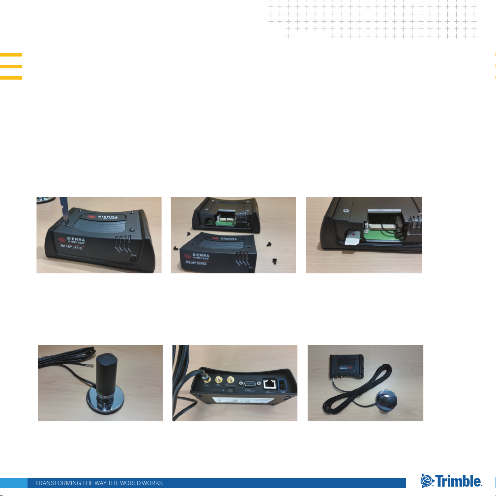
STEP 1: INSTALL THE SIM CARD
1. Ensure that the device is powered o.
2. Remove the four screws attaching the black cover to the gateway’s body and then remove the cover.
3. Slide the SIM card into the SIM card holder. Note the location of the notched corner for correct alignment.
4. Re-attach the cover using all 4 screws to maintain the IP64 rating.
STEP 2: CONNECT THE CELLULAR ANTENNA
1. Attach the supplied antenna to the magnetic antenna base. Note the rubber O-ring location to ensure a proper seal.
2. Attach the magnetic antenna base cable to the GX450 cellular connector. The GPS and Diversity connectors will not be used.
Page 2
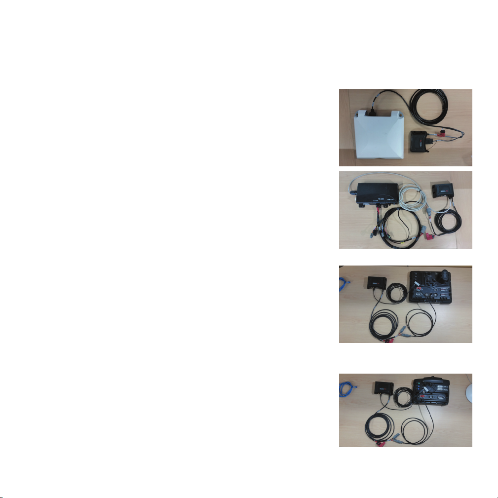
STEP 3 CONNECT THE DISPLAY OR RECEIVER
See the wiring diagrams. In all instances, ensure that the equipment is powered o before connecting it to the modem.
AG-372 receiver
1. Ensure the receiver is powered o.
2. Using cable P/N 109863, attach connector P1 to Port B on the AG-372 receiver.
3. Attach connector P2 to the serial port on the GX450 modem.
4. Attach connector P3 to the power port on the GX450 modem.
TM-200 Module
1. Ensure the TM-200 Module is powered o
2. Using cable P/N 109865, attach connector P1 to the ethernet port on the GX450 modem and
then attach connector P2 to the ethernet expansion port on the TM-200 Module or to the
expansion port on the EXP-100 module.
3. Using cable P/N 109862, attach connector P1 to the power port on the GX450 modem.
4. Connect R1 to P2 on cable P/N 92676 on the TM-200 Module.
FmX/FM-1000 integrated display
1. Ensure the display is powered o.
2. Connect USB hub P/N 83517 to the USB port on the back of the display.
3. Using cable P/N 109864, attach the USB port to the USB hub and then attach the micro USB
connector to the GX450 modem.
4. Using cable P/N 110832, connect P2 to Port A, B, C, D, or to a port replicator.
5. Attach connector P1 to connector R1 of cable P/N 109862.
6. Attach connector P1 of cable 109862 to the power port on the GX450. modem.
CFX-750 / FM-750 display
1. Ensure the display is powered o.
2. Connect the USB hub P/N 83517 to the USB port on the back of the display.
3. Using cable P/N 109864, attach the USB port to the USB hub and then attach the micro USB
connector to the GX450 modem.
4. Using cable P/N 110832, connect P2 to Port A, B, or to a port replicator.
5. Attach connector P1 to connector R1 of cable P/N 109862.
6. Attach connector P1 of cable P/N 109862 to the power port on the GX450 modem.
2
Page 3
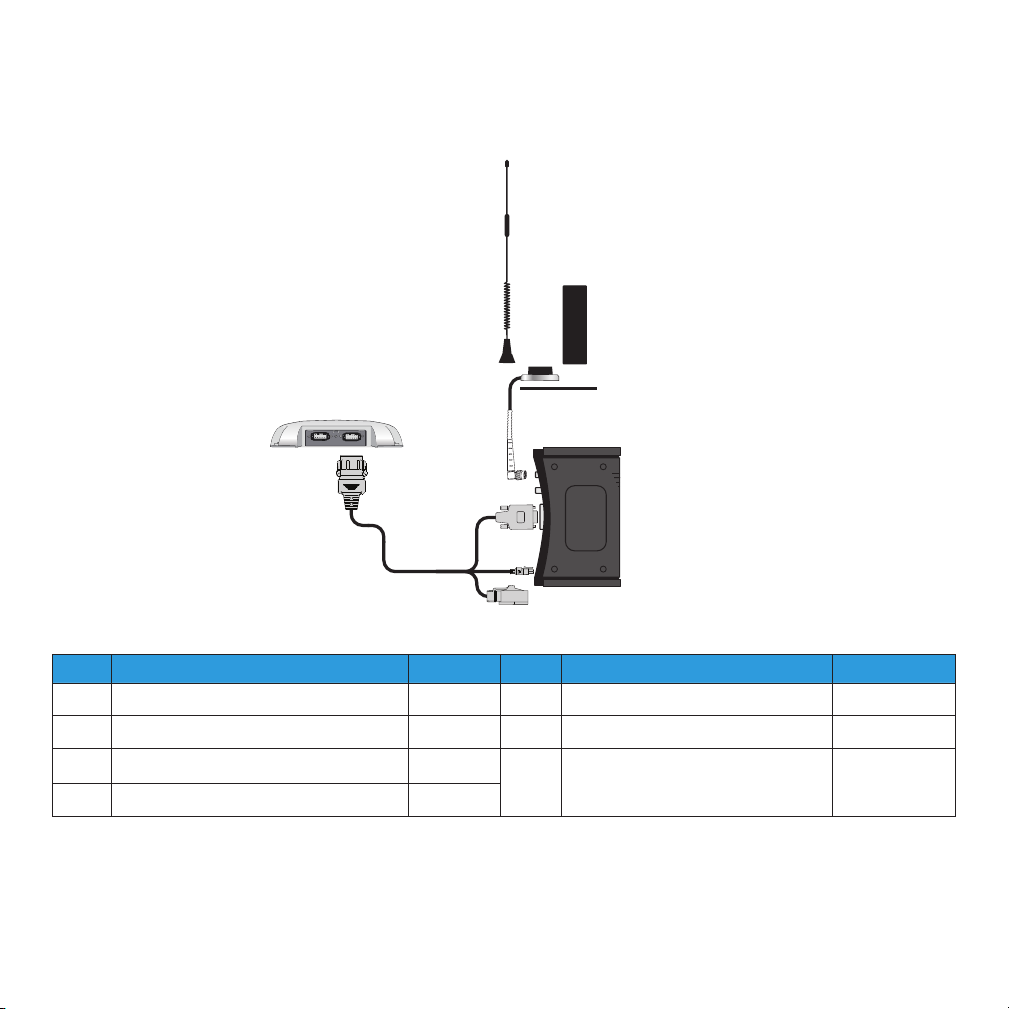
WIRING DIAGRAM: AG-372 RECEIVER
❼
❻
❶
❺
❶
❷
Item Description P/N Item Description P/N
1 AG-372 antenna 5 Mounting plate 62034
2 Power cable assembly, GX-450 modem 109863 6 Cellular antenna (international) 110024
3 GX450 modem 7 Whip antenna (USA and Canada
4 Magnetic antenna base cable 109989
❹
❸
51227
only)
3
Page 4

WIRING DIAGRAM: TM-200 MODULE (FOR USE WITH THE TMX-2050 / XCN-2050 DISPLAY)
❽
❾
❶
❶
❺
❼
❻
❷
❸
❹
Item Description P/N Item Description P/N
1 TM-200 Module 6 Mounting plate 62034
2 TM-200 14-pin power, CAN, and I/O cable 92676 7 Cellular antenna (international) 110024
3 Power cable assembly, GX450 modem 109862 8 Whip antenna (USA and Canada only) 51227
4 GX450 modem 9 Ethernet cable, GX450 modem to TM-200
5 Magnetic antenna base cable 109989
4
Module
109865
Page 5

WIRING DIAGRAM: TM-200 MODULE WITH EXP-100 PORT REPLICATOR
❶
❷
⓬
⓭
⓫
❻
❿
❾
Note: If the EXP-100 port
replicator is required and
is not already installed,
order P/N 101990-01.
If the EXP-100 port
replicator is already
installed, but without the
Ethernet adaptor,
P/N 101990-00, order
cables P/N 102730 and
P/N 100906 to attach a
GX450 modem.
❺
❸
❽
❼
❶
❹
Item Description P/ N Item Description P/N
1 Cable assembly, EXP-100 port replicator
to patch 1 meter
2 Power cable assembly, GX450 modem 109862 9 Magnetic antenna base cable 109989
3 EXP-100 port replicator 10 Mounting plate 62034
4 Cable assembly, EXP-100 adaptor to
Ethernet
5 TM-200 14-pin power, CAN, and I/O cable 92676 12 Whip antenna (USA and Canada only) 51227
6 TM-200 Module 13 Cable assembly, EXP-100 adapter
7 Ethernet cable, GX450 modem to TM-
200 Module
102730 8 GX450 modem
100906 11 Cellular antenna (international) 110024
100904
109865
TM-100 Module to Ethernet
(see also Note, above)
5
Page 6

WIRING DIAGRAM: FMX / FM-1000 INTEGRATED DISPLAY
❾
❶
❿
❽
❷
❶
❼
❻
❺
❸
❹
Item Description P/N Item Description P/N
1 USB hub 83517 6 Magnetic antenna base cable 109989
2 FmX® / FM-100™ integrated display 7 Mounting plate 62034
3 Power assembly, FmX/FM-1000 integrated
display
4 Power cable assembly, GX450 modem 109862 9 Whip antenna (USA and Canada only) 51227
5 GX450 modem 10 USB cable assembly, GX450 modem to
110832 8 Cellular antenna (international) 110024
109864
FmX /FM-1000 integrated display
6
Page 7

WIRING DIAGRAM: CFX-750 / FM-750 DISPLAY
❾
❶
❿
❽
❷
❶
❼
❻
❺
❸
❹
Item Description P/N Item Description P/N
1 USB hub 83517 6 Magnetic antenna base cable 109989
2 CFX-750™ /FM-750™ display 7 Mounting plate 62034
3 Power assembly, CFX-750 display 110832 8 Cellular antenna (international) 110024
4 Power cable assembly, GX450 modem 109862 9 Whip antenna (USA and Canada
only)
5 GX450 modem 10 USB cable assembly, GX450 modem
to CFX-750 /FM-750 display
7
51227
109864
Page 8

STEP 4: CONNECT TO THE NETWORK
The rst time the gateway is powered on its home network, it automatically starts the activation/provisioning process and attempts to
connect to the network. This process typically takes 5-10 minutes. A successful connection is indicated by a solid green network LED.
STEP 5: CONFIGURE THE NETWORK
For most cellular plans, the modem will automatically congure itself properly. If issues
persist in establishing a cellular connection (blinking red network LED) the APN may need
to be entered manually. To do this:
1. On a computer powered by a Windows® operating system (connected to the
modem using an Ethernet cable) or using the modem service tool on the
TMX-2050/XCN-2050 display that is connected to the GX450 modem, enter
http://192.168.88.3:9191 in the web browser. The ACEmanager login screen
appears.
Note: It may take the gateway 2-3 minutes to respond after the initial power up.
2. The administrator username is entered by default. Enter the default password
Wilco2016 and then click Login. The Status / Home screen appears.
3. Check the Network State eld. It should read Network Ready, which indicates that the
gateway is connected to the network. If not, refer to
STEP 4 above.
4. On the WAN/Cellular page, there is a section for User Entered APN - enter the custom
APN here if the modem does not automatically detect the cellular provider’s APN
number.
STEP 6: CONFIGURE THE CORRECTION SOURCE
Refer to the User Guide for the display or receiver for information on the setup procedure for
VRS setup.
8
Page 9

LED BEHAVIOUR
LED Color / Pattern Description
Power O
Solid green Gateway is connected to nominal power and is operating normally.
Flashing amber / green Gateway has a GPS x.
Solid amber Gateway is entering a low power mode or system low level boot.
Solid red Gateway is not operational (failure or in low power mode).
Network Solid green Network Ready (LTE service available for GX450 modem).
Flashing amber / green Network Ready (no LTE service available for GX450 modem).
Flashing green (3 s on, 1 s o) Network Ready (WAN over WiFi—gateway in WiFi client mode).
Flashing green (1 s on, 0.5 s o) Network Ready - Roaming (LTE service available for GX450 modem).
Flashing amber/green/o Network Ready - Roaming (no LTE service for GX450 modem).
Flashing amber No service.
Solid amber Connecting to the network.
Flashing red Authentication/negotiation failed (EV-DO only).
Solid red Link Down. No cellular network is present, no network coverage at current
Signal Solid green Good signal (RSSI ≥ -85 dBm).
Solid amber Marginal signal (-100 dBm, < RSSI <-85 dBm).
Solid red Poor signal (-110 dBm ≤ RSSI ≤ -100 dBm).
Flashing red No signal, RSSI (< -100 dBm).
Activity (ALEOS
4.4.0 or later)
O Normal operation.
Flashing green Trac is being transmitted or received over the WAN interface.
Flashing red Trac is being transmitted or received over the serial port. This behavior
Flashing amber Trac is being transmitted or received over both the WAN interface and
No power or input voltage ≥ 36 VDC or ≤ 9 VDC.
location, or the gateway is in radio passthru mode.
only appears if the AirLink GX Series gateway is congured to display it.
Refer to the ALEOS Software Conguration Guide for details.
the serial port. This behavior only appears if the AirLink GX Series gateway
is congured to display it. Refer to the ALEOS Software Conguration
Guide for details.
9
Page 10

TRANSFORMING THE WAY THE WORLD WORKS
FIRMWARE VERSION MATRIX
Product Update to the following software version
FmX / FM-1000 integrated display
CFX-750 / FM-750 display Version 7.71 or later, released October 2016
TMX-2050™ / XCN-2050™ display Version 4.31 or later, released December 2016
AG-372 antenna Version 6.20 or later, released April 2016
Version 10.01 or later, released December 2016
© 2016, Trimble Inc. All rights reserved. Trimble, the Globe & Triangle logo, and FmX are trademarks of Trimble Inc., registered in the United States and
in other countries. FieldLevel, FM-750, FM-1000, TMX-2050, and XCN-2050 are trademarks of Trimble Inc. Microsoft and Windows are either registered
trademarks or trademarks of Microsoft Corporation in the United States and/or other countries. All other trademarks are the property of their respective
owners. Version 1.00, Rev A (November 2016). P/N 110896-00-ENG
*110896-00-ENG*
Trimble Inc.
10368 Westmoor Drive
Westminster CO 80021
USA
 Loading...