

Page 1

AirLink ES Series
Hardware User Guide
4116746
Rev 4
Page 2

Page 3

Preface
Important
Notice
Safety and
Hazards
Due to the nature of wireless communications, transmission and reception of data
can never be guaranteed. Data may be delayed, corrupted (i.e., have errors) or be
totally lost. Although significant delays or losses of data are rare when wireless
devices such as the Sierra Wireless modem are used in a normal manner with a
well-constructed network, the Sierra Wireless modem should not be used in
situations where failure to transmit or receive data could result in damage of any
kind to the user or any other party, including but not limited to personal injury,
death, or loss of property. Sierra Wireless accepts no responsibility for damages
of any kind resulting from delays or errors in data transmitted or received using
the Sierra Wireless modem, or for failure of the Sierra Wireless modem to
transmit or receive such data.
Do not operate the Sierra Wireless modem in areas where blasting is in progress,
where explosive atmospheres may be present, near medical equipment, near life
support equipment, or any equipment which may be susceptible to any form of
radio interference. In such areas, the Sierra Wireless modem MUST BE
POWERED OFF. The Sierra Wireless modem can transmit signals that could
interfere with this equipment.
The driver or operator of any vehicle should not operate the Sierra Wireless
modem while in control of a vehicle. Doing so will detract from the driver or
operator's control and operation of that vehicle. In some states and provinces,
operating such communications devices while in control of a vehicle is an offence.
Limitation of
Liability
The information in this manual is subject to change without notice and does not
represent a commitment on the part of Sierra Wireless. SIERRA WIRELESS AND
ITS AFFILIATES SPECIFICALLY DISCLAIM LIABILITY FOR ANY AND ALL
DIRECT, INDIRECT, SPECIAL, GENERAL, INCIDENTAL, CONSEQUENTIAL,
PUNITIVE OR EXEMPLARY DAMAGES INCLUDING, BUT NOT LIMITED TO,
LOSS OF PROFITS OR REVENUE OR ANTICIPATED PROFITS OR REVENUE
ARISING OUT OF THE USE OR INABILITY TO USE ANY SIERRA WIRELESS
PRODUCT, EVEN IF SIERRA WIRELESS AND/OR ITS AFFILIATES HAS BEEN
ADVISED OF THE POSSIBILITY OF SUCH DAMAGES OR THEY ARE
FORESEEABLE OR FOR CLAIMS BY ANY THIRD PARTY.
Notwithstanding the foregoing, in no event shall Sierra Wireless and/or its
affiliates aggregate liability arising under or in connection with the Sierra Wireless
product, regardless of the number of events, occurrences, or claims giving rise to
liability, be in excess of the price paid by the purchaser for the Sierra Wireless
product.
Rev 4 Aug.15 3
Page 4
AirLink ES Series Hardware User Guide
Patents This product may contain technology developed by or for Sierra Wireless Inc. This
product includes technology licensed from QUALCOMM
manufactured or sold by Sierra Wireless Inc. or its affiliates under one or more
patents licensed from InterDigital Group and MMP Portfolio Licensing.
®
. This product is
Copyright © 2015 Sierra Wireless. All rights reserved.
Trademarks Sierra Wireless
registered trademarks of Sierra Wireless.
Windows
Corporation.
Macintosh
the U.S. and other countries.
QUALCOMM
under license.
Other trademarks are the property of their respective owners.
Contact
International Contact Information
®
, AirPrime®, AirLink®, ALEOS® and the Sierra Wireless logo are
®
and Windows Vista® are registered trademarks of Microsoft
®
and Mac OS X® are registered trademarks of Apple Inc., registered in
®
is a registered trademark of QUALCOMM Incorporated. Used
Information
Contact Email or Web Site
Sales:
Sierra Wireless AirLink Sales
Technical support:
Contact your authorized AirLink reseller.
Company information:
New products, press releases, and
more
airlinksales@sierrawireless.com
Additional support resources, such as technical
documentation and software downloads are
available at: source.sierrawireless.com
www.sierrawireless.com
Sierra Wireless Headquarters Contact Information
Postal Address: Sierra Wireless
13811 Wireless Way
Richmond, BC
Canada V6V 3A4
www.sierrawireless.com
4 4116746
Page 5

Contents
Introducing the AirLink ES Series . . . . . . . . . . . . . . . . . . . . . . . . . . . . . . . . . . .7
Introduction. . . . . . . . . . . . . . . . . . . . . . . . . . . . . . . . . . . . . . . . . . . . . . . . . . . 7
Out-of-Band Management (OOBM) . . . . . . . . . . . . . . . . . . . . . . . . . . . . . .8
Network Configuration . . . . . . . . . . . . . . . . . . . . . . . . . . . . . . . . . . . . . . . . . . 9
Device Description . . . . . . . . . . . . . . . . . . . . . . . . . . . . . . . . . . . . . . . . . . . . . 9
Front Panel . . . . . . . . . . . . . . . . . . . . . . . . . . . . . . . . . . . . . . . . . . . . . . . .9
Rear Panel . . . . . . . . . . . . . . . . . . . . . . . . . . . . . . . . . . . . . . . . . . . . . . . .10
ALEOS Software . . . . . . . . . . . . . . . . . . . . . . . . . . . . . . . . . . . . . . . . . . . . . 11
ACEmanager . . . . . . . . . . . . . . . . . . . . . . . . . . . . . . . . . . . . . . . . . . . . . .12
ACEview . . . . . . . . . . . . . . . . . . . . . . . . . . . . . . . . . . . . . . . . . . . . . . . . .12
AirLink Management Service . . . . . . . . . . . . . . . . . . . . . . . . . . . . . . . . . .12
Accessories . . . . . . . . . . . . . . . . . . . . . . . . . . . . . . . . . . . . . . . . . . . . . . . . . 13
Ordering Information . . . . . . . . . . . . . . . . . . . . . . . . . . . . . . . . . . . . . . . . . . 13
Warranty. . . . . . . . . . . . . . . . . . . . . . . . . . . . . . . . . . . . . . . . . . . . . . . . . . . . 13
Startup and Configuration . . . . . . . . . . . . . . . . . . . . . . . . . . . . . . . . . . . . . . . .15
Initial Startup and Configuration. . . . . . . . . . . . . . . . . . . . . . . . . . . . . . . . . . 15
Tools and Materials Required . . . . . . . . . . . . . . . . . . . . . . . . . . . . . . . . .15
Installing the SIM Card . . . . . . . . . . . . . . . . . . . . . . . . . . . . . . . . . . . . . . .16
Connecting the Antennas . . . . . . . . . . . . . . . . . . . . . . . . . . . . . . . . . . . . .16
Connecting the Power Cable and Starting the ES Series Device . . . . . .18
Connecting the Configuration PC . . . . . . . . . . . . . . . . . . . . . . . . . . . . . .18
Connecting the Enterprise Router or other Equipment . . . . . . . . . . . . . .19
Configuring with ACEmanager. . . . . . . . . . . . . . . . . . . . . . . . . . . . . . . . . . . 21
Configuring with AirLink Management Service. . . . . . . . . . . . . . . . . . . . . . . 22
Configuring with AT Commands. . . . . . . . . . . . . . . . . . . . . . . . . . . . . . . . . . 23
LED Behavior. . . . . . . . . . . . . . . . . . . . . . . . . . . . . . . . . . . . . . . . . . . . . . . . 23
On-site Installation and Setup . . . . . . . . . . . . . . . . . . . . . . . . . . . . . . . . . . . . .27
Typical Configuration . . . . . . . . . . . . . . . . . . . . . . . . . . . . . . . . . . . . . . . . . . 27
Rev 4 Aug.15 5
Page 6

AirLink ES Series Hardware User Guide
Locating the ES Series device. . . . . . . . . . . . . . . . . . . . . . . . . . . . . . . . . . . 28
Mounting the ES Series device . . . . . . . . . . . . . . . . . . . . . . . . . . . . . . . . . . 29
Antenna Installation. . . . . . . . . . . . . . . . . . . . . . . . . . . . . . . . . . . . . . . . . . . 29
Antenna Recommendations . . . . . . . . . . . . . . . . . . . . . . . . . . . . . . . . . . . . 30
Antenna Separation . . . . . . . . . . . . . . . . . . . . . . . . . . . . . . . . . . . . . . . . . 30
Connecting the Enterprise Router . . . . . . . . . . . . . . . . . . . . . . . . . . . . . . . . 31
Power Connector on the ES Series Gateway . . . . . . . . . . . . . . . . . . . . . 31
Fusing . . . . . . . . . . . . . . . . . . . . . . . . . . . . . . . . . . . . . . . . . . . . . . . . . . . 32
Grounding the ES Series Gateway Chassis . . . . . . . . . . . . . . . . . . . . . . 32
Local Management . . . . . . . . . . . . . . . . . . . . . . . . . . . . . . . . . . . . . . . . . . . 35
Remote Management . . . . . . . . . . . . . . . . . . . . . . . . . . . . . . . . . . . . . . . . . 35
AirLink ES Series Specifications . . . . . . . . . . . . . . . . . . . . . . . . . . . . . . . . . . 37
Radio Module Conducted Transmit Power . . . . . . . . . . . . . . . . . . . . . . . 41
Host Interfaces. . . . . . . . . . . . . . . . . . . . . . . . . . . . . . . . . . . . . . . . . . . . . . . 44
Environmental . . . . . . . . . . . . . . . . . . . . . . . . . . . . . . . . . . . . . . . . . . . . . . . 44
Mechanical Specifications . . . . . . . . . . . . . . . . . . . . . . . . . . . . . . . . . . . . . . 47
Antenna Specifications . . . . . . . . . . . . . . . . . . . . . . . . . . . . . . . . . . . . . . . . 48
AC Power Adapter Specifications . . . . . . . . . . . . . . . . . . . . . . . . . . . . . . . . 48
AC Power Adapter Regulatory Standards . . . . . . . . . . . . . . . . . . . . . . . . 50
Regulatory Information . . . . . . . . . . . . . . . . . . . . . . . . . . . . . . . . . . . . . . . . . . 51
Federal Communications Commission Notice (FCC United States) . . . . 51
Important Information for North American Users on Radiation Exposure 51
Europe Generic Devices . . . . . . . . . . . . . . . . . . . . . . . . . . . . . . . . . . . . . 52
Acronyms. . . . . . . . . . . . . . . . . . . . . . . . . . . . . . . . . . . . . . . . . . . . . . . . . . . . . 53
Index. . . . . . . . . . . . . . . . . . . . . . . . . . . . . . . . . . . . . . . . . . . . . . . . . . . . . . . . . 57
6 4116746
Page 7

1: Introducing the AirLink ES Series
1
This chapter describes the Sierra Wireless AirLink ES Series device,
including a description of ALEOS
AirLink Management Service (ALMS) device management platform.
®
embedded software and the
Introduction
The Sierra Wireless ES Series enterprise gateways deliver missioncritical 4G LTE connectivity when primary landline connections are
unavailable. When deployed with an enterprise router, ES Series
devices support a best-in-class business continuity strategy by
enabling out-of-band management (OOBM) capability to network
operations while leveraging the router's instant failover, routing, and
firewall features.
You can also configure ES Series devices to send their management
data via the DSL/cable gateway using reliable static route protocol to
reduce wireless network costs.
Additional benefits to this enterprise-class business continuity
solution include:
• Improved Internet uptime to keep your branches, kiosks, and
retail operations online
• Seamless failover for continuous uptime of mission critical applications
• High speed LTE network, faster than xDSL
• Reduced field visits for network equipment resets and updates
• ALEOS and ACEmanager web-based configuration that makes it
quick to deploy
• AirLink Management Service cloud-based device management
application that works in parallel with your network management
systems to manage the wireless system
• ALEOS reliable connection software ensures that the ES Series
device stays connected to the wireless network
• Better SLAs (Service Level Agreements) offered from the
Network Operation Centers as a result of the wireless backup
offered by ES Series devices
Rev 4 Aug.15 7
Page 8
AirLink ES Series Hardware User Guide
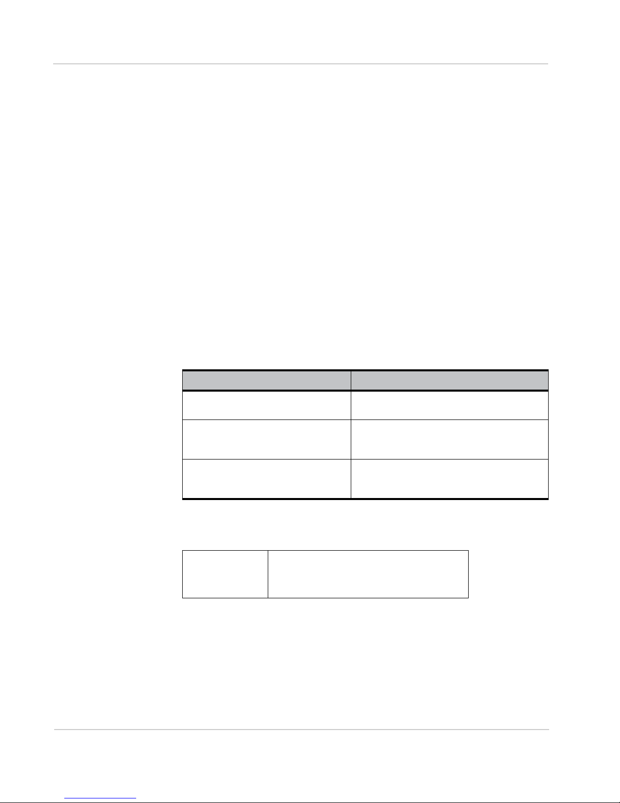
Inventory
POS
NOCS
HQ
VoIP phone
Wireline Gateway
MNO
Internet
Enterprise-grade router/firewall
Wi-Fi AP
OOBM
AirLink ES Series
(serial to console port)
Wi-Fi AP
Laptop
Wireless backup Primary wireless
Ethernet Switch
device
AirLink ES Series
device
Figure 1-1: AirLink ES Series applications
Out-of-Band Management (OOBM)
Using the ES Series device's serial port to connect to the console port of the
router, IT administrators can troubleshoot and repair network equipment over
wireless wide area networks (WANs). This terminal server capability allows
operation centers to remotely reboot, configure, and update the BIOS of a router
via the ES Series enterprise gateway using Reverse Telnet and SSH protocols.
As a result, remote personnel no longer need to manually reset their networking
equipment and IT administrators can dramatically reduce the number of field
visits.
8 4116746
Page 9
Introducing the AirLink ES Series
LEDs
Reset Button
Network Configuration
ES Series devices are designed for the distributed enterprise, which includes any
enterprise that has remote facilities that must maintain a network connection for
critical business processes such as retail credit card transactions.
If you are using an ES Series device for a point-of-sales application, you can
configure it to meet PCI Data Security Standard compliance requirements.
ALEOS features such as Reverse Telnet and Reliable Static Routing also support
point-of-sale applications. Refer to the ALEOS Software Configuration User
Guide for details.
Device Description
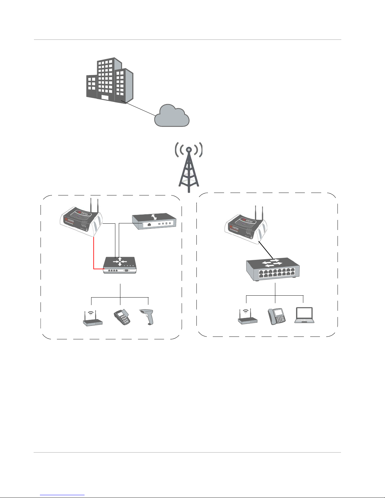
Front Panel
The front panel has the following indicators and controls:
Figure 1-2: ES Series Device Front Panel
•LEDs – These show the ES Series device’s operating status. The LEDs are
described in detail in LED Behavior on page 23.
• Reset Button – Momentarily pressing and releasing this button reboots the
ES Series device.
Note: Holding the Reset bu tton down for 7–10 seconds resets the ES Series device to its
factory default settings.
Rev 4 Aug.15 9
Page 10
AirLink ES Series Hardware User Guide
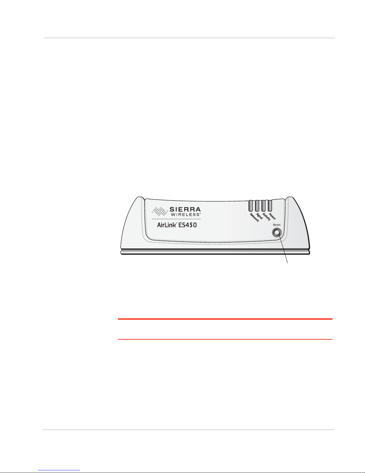
Primary LTE Antenna Connector
Secondary LTE
Antenna Connector
Power Connector
USB Port Serial Port
Ethernet
Connector
Rear Panel
The rear panel has the following connectors and controls:
Figure 1-3: ES Series Rear Panel
• Primary LTE Antenna Connector – This is the radio’s receive and transmit
port. For best results, use the included antennas, placed in a V formation. You
can attach the antennas directly to the ES Series device, or you can use a
bracket and SMA coaxial cable to connect antennas located away from the
device.
• Secondary LTE Antenna Connector – This is required for LTE MIMO
(multiple-input and multiple-output).
Note: For more information, see Connecting the Antennas on page 16.
• Ethernet Connector – This RJ-45 connector connects any Ethernet-enabled
network equipment to the ES Series device using a standard Ethernet cable.
It is also used to connect a Windows PC that you can use to configure and
monitor the ES Series device, using ACEmanager.
This connector complies with the IEEE 802.3 specification for 100 Mbps
speed (Fast Ethernet) with fallback to 10 Mbps and includes auto-crossover
support. It is auto-sensing and auto-detects the speed of the connecting
device for 100 baseT or 10 baseT.
The connector has two LEDs that indicate speed and activity. For more information, see Ethernet LEDs on page 24.
• Power Connector – Connect the AC adapter or DC cable.
The ES Series device automatically starts when power is supplied.
• Serial Port – This 9-pin connector provides standard RS-232 DCE communication. For out-of-band management, you can connect this serial port to an
enterprise router. You can also connect a computer to the serial port to
configure the ES Series device using AT commands. For more information,
see Connecting the Enterprise Router or other Equipment on page 19.
•USB Port – The Micro AB connector complies with version 2.0 of the USB
standard for high-speed operation. It accepts Micro A and Micro B plugs. You
can connect a Windows PC to monitor and configure the ES Series device.
10 4116746
Page 11

Introducing the AirLink ES Series
When connected to a PC, the USB port becomes either a:
· Virtual serial port (The ES Series device behaves as if the PC is connected
to a standard serial port. The primary use of this interface is to send AT
commands.)
· Virtual Ethernet port (The ES Series device behaves as if the PC is
connected to an Ethernet port, allowing access to the Internet and
ACEmanager. This is the default setting.)
Refer to the ALEOS Software Configuration User Guide for information on
configuring the USB port. Windows drivers for the USB port are available at
Sierra Wireless’ download web site: source.sierrawireless.com.
When using the USB port:
· Use a USB 2.0 cable
· Connect directly to your computer for best throughput
ALEOS Software
Note: For detailed information on all of the features in ALEOS, see the ALEOS Software
Configuration User Guide available for downloading from source.sierrawireless.com.
ALEOS, the embedded core technology of the AirLink product line, provides:
• An always-on, always-aware, intelligent two-way connection for missioncritical applications
• Simplified setup, operation and maintenance of any wireless solution
ALEOS features include:
• Reverse Telnet for out-of-band management
• Reliable Static Routing
• SNMP
• Persistent Network Connectivity
• Over-The-Air (OTA) Upgrades
• Wireless Optimized TCP/IP
• Real-Time Notification
• Packet Level Diagnostics
• Device Management & Control
Sierra Wireless has two main applications for monitoring and configuring
ES Series devices:
• ACEmanager – A web-based configuration tool for configuring a single
AirLink device
• AirLink Management Service (ALMS) – A cloud-based device management
service for monitoring and configuring fleets of ES Series devices.
ES Series devices also accept AT Commands.
Rev 4 Aug.15 11
Page 12
AirLink ES Series Hardware User Guide
ACEmanager
ACEmanager is a web-based application used to configure and monitor
ES Series devices. ACEmanager:
• Simplifies deployment
• Provides extensive monitoring, control and management capabilities
• Enables you to configure your ES Series device to meet your needs
• Monitors and controls your ES Series device remotely and in real-time
• Is accessed through a web browser connected to the ES Series device locally
or over the air.
See Configuring with ACEmanager on page 21 to learn how to access
ACEmanager.
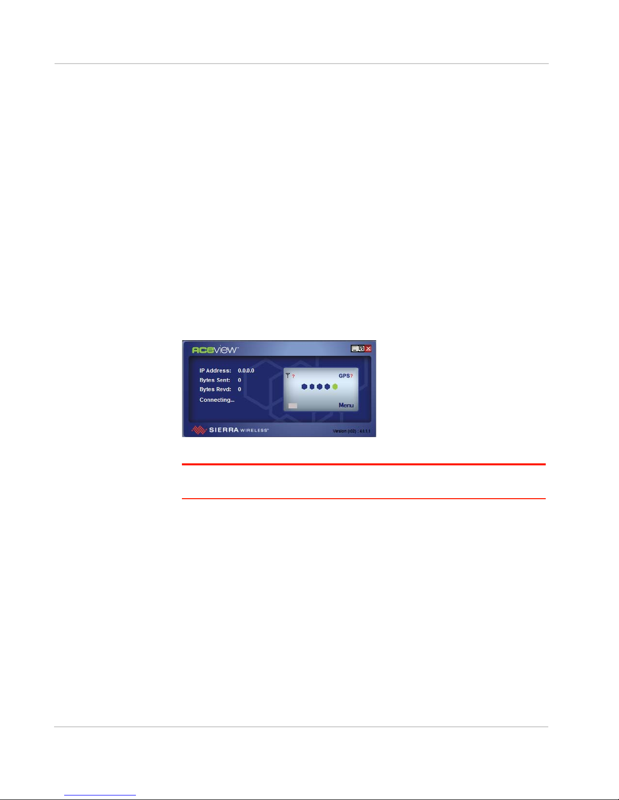
ACEview
ACEview is a Windows-based monitoring application for the PC with an easy to
read interface. You can download ACEview free of charge from:
source.sierrawireless.com.
Figure 1-4: ACEview Screen
Note: ACEview requires the Micros oft .NET Framework v.2.0 and Microsoft Windows XP
or later. Obtain the Microsoft .NET Framework from Microsoft at: http://www.microsoft.com.
AirLink Management Service
AirLink Management Service (ALMS) is a cloud-based application, accessible
from your web browser. It provides remote monitoring and configuration for
multiple AirLink ALEOS devices from a single computer.
ALMS features include:
• Device management as a service
• Advanced monitoring dashboards and alert notifications ensuring you always
know the status of your ES Series devices
• Detailed configuration of all ALEOS parameters, including templates
providing batch updates of pre-set configurations across multiple devices
• Over-the-air (OTA) firmware upgrades for all of your ES Series devices with a
single operation
For more information about ALMS, go to www.sierrawireless.com/ALMS.
12 4116746
Page 13

Introducing the AirLink ES Series
Accessories
• Included with the ES Series device:
· AC power adapter with international plug options
· Mounting screws
· Two LTE antennas
· Quick Start Guide
• Order separately:
· Ethernet cable
· DB-9 serial cable (6 ft and 25 ft lengths)
· USB cable
· Null modem cable
Ordering Information
For more information or to place an order, contact:
airlinksales@sierrawireless.com.
Warranty
The ES Series device has a 3-year standard warranty.
Rev 4 Aug.15 13
Page 14

AirLink ES Series Hardware User Guide
14 4116746
Page 15

2: Startup and Configuration
This chapter provides instruction for the initial device configuration,
and describes the front panel LEDs.
Initial Startup and Configuration
Follow the instructions in this section to do the initial startup and
configuration for the ES Series device. For on-site installation and
setup instructions, see On-site Installation and Setup on page 27.
Tools and Materials Required
• A SIM card for your ES Series device (provided by your mobile
network operator) if not already installed
• A Phillips screwdriver for removing the top cover
• A laptop computer with an Ethernet, USB, or serial cable for
device management
• Two LTE wireless antennas (included) For indoor use only.
• AC power adapter (included)
• If wireless out-of-band management is required, a null modem
cable to connect the ES Series device’s RS-232 port to the enterprise router
• If you are mounting the antennas remotely from the ES Series
device, you will need a coaxial cable, mounting brackets, and
connectors. (For more information, see Antenna Installation on
page 29.)
2
Rev 4 Aug.15 15
Page 16
AirLink ES Series Hardware User Guide
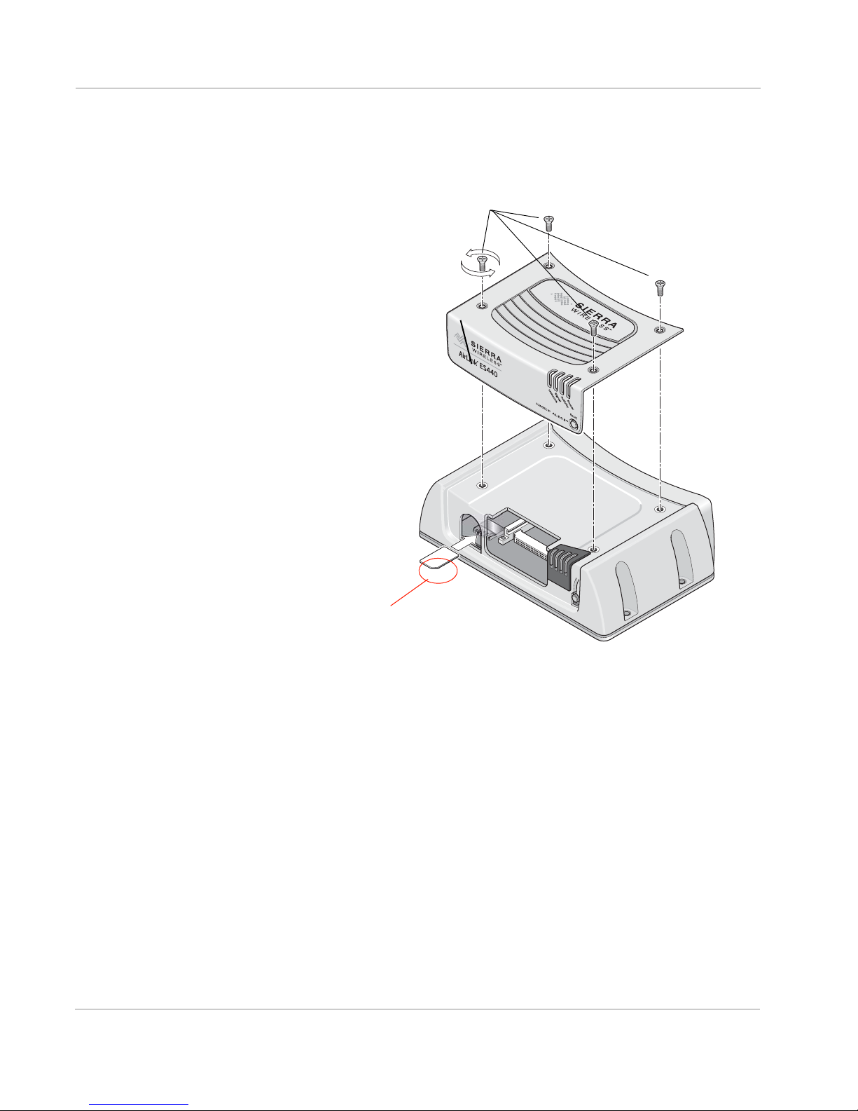
1) Use a Phillips screwdriver to
2) Remove the cover.
3) Slide the SIM card
into the SIM card holder.
Note the orientation of notched
4) Reattach the cover, ensuring that the Phillips screws are tightened to 5 in-lb (0.6 N-m).
corner of SIM card for
proper alignment.
Over-tightening can damage the threads in the aluminum housing.
remove the four screws attaching the cover.
Save the screws for re-installation.
Installing the SIM Card
If it is not already installed, insert a SIM card into the ES Series device before
connecting any external equipment or powering it up.
16 4116746
Figure 2-1: SIM Card Installation
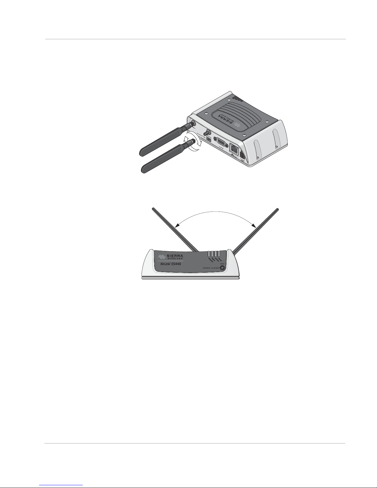
Connecting the Antennas
The primary and secondary RF antennas can be:
• Attached directly to the ES Series device
They operate well when the antenna blades are placed in a V position, with 90
degrees of separation.
• Placed remotely using brackets, and connected to the ES Series device using
a coaxial cable
This may be required if you want to place the ES Series device in an area that
does not have optimal signal strength or is near RF noise interference (such
as near an enterprise router)
Page 17
Startup and Configuration
90°
An RF site survey may be required to determine the best location. See
Antenna Installation on page 29.
To connect the antennas to the device:
1. Connect both RF antennas, as shown in the illustration.
2. Adjust the antennas so they are in a V-formation, with a separation of
90 degrees.
Rev 4 Aug.15 17
Page 18
AirLink ES Series Hardware User Guide
PUSH
PUSH
PUSH
PUSH
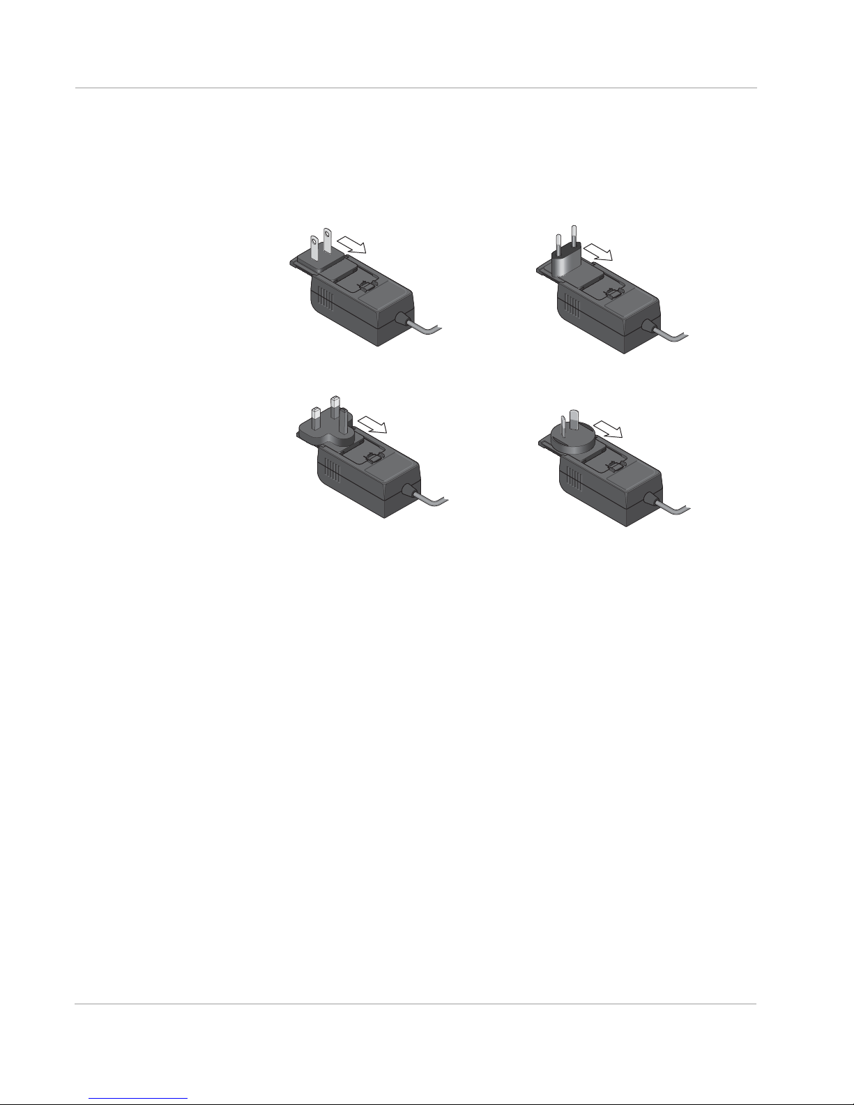
North America
Europe
UK
Australia
Connecting the Power Cable and Starting the
ES Series Device
1. Choose the correct AC adapter plug for your region and slide it into the AC
adapter base.
PUSH
PUSH
PUSH
PUSH
2. Connect the power cable to the 4-pin power connector on the ES Series
device.
3. Plug the adapter into an AC wall outlet. (If you use a cable to connect the
device to a DC power source, see Power Connector on the ES Series
Gateway on page 31.)
Characteristics of the ES Series device power supply:
· 100–240 V
· 50/60 Hz.
· 9–36 VDC, 1500 mA output
4. The ES Series device starts automatically, as indicated by the flashing LEDs.
See LED Behavior on page 23 for details.
Connecting the Configuration PC
To connect the computer to the ES Series device:
1. Use an Ethernet cable to connect the ES Series device to the PC.
If the Ethernet port is being used to connect another device, such as an enterprise router, you can connect the USB port on the ES Series device to the
computer and configure it to act as a virtual Ethernet port. See Figure 2-2 on
page 19.
18 4116746
Page 19

Startup and Configuration
Ethernet
cable
Ethernet
cable
USB cable
Ethernet Connection Virtual Ethernet Connection with USB cable
If you are using the Ethernet
port on the ES Series device to
connect an enterprise
router, then use the USB
port to connect the PC
and configure it to be a
virtual Ethernet port.
If you are not using the Ethernet
port on the ES Series device to connect an
enterprise router, the easiest way
to connect the PC is to use an
Ethernet cable.
Figure 2-2: Connecting the ES Series device to the PC
2. If you are using a USB cable:
a. Download the USB drivers from source.sierrawireless.com.
b. Install the USB drivers.
c. Reboot the PC.
3. Use the appropriate cable (Ethernet or USB) to connect the PC to the
ES Series device.
Connecting the Enterprise Router or other
Equipment
1. Use a serial cable to connect one of the WAN ports on the enterprise router
to the RS-232 serial connector on the ES Series device.
Note: The ES Series device is a DCE serial device. The enterpri se router may have an
RJ-45 or DB-9 console port. Depending on the type of console port connectors and the
cable available from the enterprise router vendor, you may need to purchase additional
cables, including a null modem cable from the enterprise router vendor.
Rev 4 Aug.15 19
Page 20

AirLink ES Series Hardware User Guide
Wired gateway
ES Series device
Enterprise router
Redundant ISP configuration Out-Of-Band Management Configuration
Enterprise router
ES Series device
Null modem cable
5
987 6
43 21
Figure 2-3: Connecting an enterprise router to an ES Series device
The ES Series device’s serial connector complies with the EIA RS-232D
specification for DCE equipment. The output driver levels range from -7 VDC to
+7 VDC with normal loading.
20 4116746
Figure 2-4: 9-Pin Serial Connector Diagram
Table 2-1: Serial Connector Pin-out
Name Pin Description Type
DCD 1 Data Carrier Detect OUT
TXD 2 Transmit Data OUT
RXD 3 Receive Data IN
DTR 4 Data Terminal Ready IN
GND 5 Main GND. Connected
internally to BOARD_GND
DSR 6 Data Set Ready OUT
RTS 7 Ready To Send IN
CTS 8 Clear To Send OUT
RI 9 Ring Indicator OUT
GND
Page 21

Startup and Configuration
Configuring with ACEmanager
To access ACEmanager:
1. Ensure that the ES Series device is powered on and connected to a PC.
2. Open a web browser and in the address bar, enter:
http://192.168.13.31:9191.
Note: It may take a minute or two for the ES Series device to respond after the first power
up.
The ACEmanager login screen appears.
3. The default user name, user, is already entered. Enter the default password,
12345.
Figure 2-5: ACEmanager Login Screen
4. Click Log In.
The ACEmanager Status > Home page appears
Figure 2-6: ACEmanager Homepage
1
.
5. If the device does not automatically connect to the network:
a. Check the Network State field. It should say “Network Ready”. If it says
No SIM or Unexpected SIM, check that the correct SIM card is inserted.
Rev 4 Aug.15 21
1. The appearance of the screen varies dependi ng on the version of ALEOS installed
on the device and the type of network the device is connected to.
Page 22

AirLink ES Series Hardware User Guide
(See Installing the SIM Card on page 16.)
b. Check the Signal Strength field. It should be greater than -100.
c. Check the APN on the WAN/Cellular tab. If an error message appears in
this field, contact your Mobile Network Operator. They may need to
provide you with an APN to enter in the User Entered APN field.
Figure 2-7: ACEmanager: WAN/Cellular
To configure the device using ACEmanager, refer to the ALEOS Software
Configuration User Guide, available for download from source.sierrawireless.com.
After the ES Series device is connected and configured, you can save the
configuration as a template to the configuration PC and then apply this template
to subsequent ES Series devices. For details, refer to the ALEOS Software
Configuration User Guide.
Configuring with AirLink Management
Service
AirLink Management Service (ALMS) is a cloud-based service that provides
remote monitoring and configuration for multiple AirLink devices.
To use ALMS, you must have an account. For more information, go to
www.sierrawireless.com/ALMS.
To access AirLink Management Service:
1. Connect a laptop to the ES Series device with an Ethernet cable.
2. Log in to ACEmanager.
3. Go to the Services tab and ensure that ALMS is enabled and the server URL
is http://na.m2mop.net/msci/com. If this is not the case, enter the correct
URL, click Apply and then click Reboot.
4. In your browser, go to http://airvantage.net and log in.
5. Follow the instructions in the online ALMS documentation to register your
device.
22 4116746
Page 23

Startup and Configuration
Configuring with AT Commands
You can also configure ES Series devices using AT commands over the RS-232
serial port or the USB port (configured as a virtual serial port). All the commands
are listed in the ALEOS Software Configuration User Guide.
• Most AT commands are prefaced with AT. Exceptions are noted in the ALEOS
Configuration User Guide.
• The acceptable format and parameters are listed with each command in the
ALEOS Configuration User Guide.
• If you enter a recognized AT command, the ES Series device responds with
“OK.” If the command is wrong, the ES Series device responds with “ERROR”
or “Unsupported.”
LED Behavior
Table 2-2: LED Behavior
LED Color /Pattern Description
Power Off No power or input voltage ≥36 VDC or ≤9 VDC
Solid Green Device is connected to nominal power and is operating normally.
Solid Yellow Device is entering low power mode or system low level boot.
Solid Red Device is not operational (failure or in low power mode).
Signal Solid Green Good signal
(RSSI
≥ -85 dBm)
Solid Yellow Marginal signal (-100 dBm < RSSI < -85 dBm)
Solid Red Poor signal (-110 dBm ≤ RSSI ≤ -100 dBm)
Flashing Red No signal (RSSI < -110 dBm)
Network Solid Green Network Ready (LTE service available)
Flashing Yellow /Green Network Ready (No LTE service available)
Flashing Green Network Ready—Roaming (LTE service available)
Flashing Yellow /Green/Off Network Ready—Roaming (No LTE service available)
Flashing Yellow No Service
Solid Yellow Connecting to the network
Flashing Red Authentication/Negotiation failed (EV-DO only)
Solid Red Link Down
No cellular network is present, no network coverage at current
location, or the device is in radio passthru mode
Activity
(ALEOS
4.3.6 or
earlier)
Off Normal operation
Flashing Green Traffic is being transmitted or received over the WAN interface.
Rev 4 Aug.15 23
Page 24

AirLink ES Series Hardware User Guide
Connection speed
Activity
Table 2-2: LED Behavior
LED Color /Pattern Description
Activity
(ALEOS
4.4.0 or
later)
Off Normal operation
Flashing Green Traffic is being transmitted or received over the WAN interface.
Flashing Red Traffic is being transmitted or received over the serial port. (This
behavior only appears if the AirLink ES Series device is configured
to display it. Refer to the ALEOS Software Configuration Guide for
details.)
Flashing Yellow Traffic is being transmitted or received over both the WAN interface
and the serial port. (This behavior only appears if the AirLink
ES Series device is configured to display it. Refer to the ALEOS
Software Configuration Guide for details.)
Ethernet LEDs
Figure 2-8: Ethernet LEDs
The Ethernet port has two LEDs that indicate speed and activity. When looking
into the connector:
• Activity— The right LED is solid yellow when a link is detected (the cable is
plugged in) and blinks when there is activity.
• Connection Speed— The left LED is green to indicate a 100 Mbps connection
and orange to indicate a 10 Mbps connection. It is off when no cable is
connected.
Power-up and Reboot
On power-up or reboot, the LEDs go through a booting sequence. When the boot
is complete, the Power and Network LEDs should be green, signifying that the
power is on, the ES Series device is connected to the wireless network, and there
is a good signal. See Ta bl e 2 - 2 for detailed LED operation.
To reboot the ES Series device, either:
• In ACEmanager, click the Reboot button at the top right of the screen.
Or
24 4116746
Page 25

Startup and Configuration
• Press and release the Reset button on the ES Series device (see Front Panel
on page 9).
Reset to factory default settings
To reset the ES Series device to the factory default settings, either:
• Press and hold the Reset button until all the LEDs turn greenish-yellow
(about 7–10 seconds). See Front Panel on page 9.
Or
• In ACEmanager, go to Admin > Advanced and click the Reset to Factory
Default button. For details, refer to the ALEOS Software Configuration User
Guide.
The ES Series device resets to the factory default settings and reboots. Once
the reboot is complete and the LEDs resume their normal operating behavior,
the reset is complete.
Rev 4 Aug.15 25
Page 26

AirLink ES Series Hardware User Guide
26 4116746
Page 27

3: On-site Installation and Setup
InventoryPOS VoIP phone
Wireline Gateway
Internet
Enterprise-grade router/firewall
Wi-Fi AP
OOBM
AirLink ES Series
(serial to console port)
Wireless backup
Switch
Primary
Remote enterprise locations
Network Operations Center
Headquarters (Inventory, Operations)
Payment Processor
(Secure Credit and Debit,
PCI Compliance)
device
This chapter shows you how to communicate with and configure the
Sierra Wireless AirLink ES Series device.
Typical Configuration
The ES Series device is a purpose-built 4G LTE gateway and
terminal server. When deployed with an enterprise router, the
ES Series device supports a best-in-class business continuity
strategy by enabling out-of-band management (OOBM) capability to
network operations, while leveraging the router’s instant failover,
routing, and firewall features. Figure 3-1 shows the typical
connections.
3
Rev 4 Aug.15 27
Figure 3-1: Network for Distributed Enterprise Business Continuity Model
Page 28

AirLink ES Series Hardware User Guide
When using the ES Series device in the configuration shown in Figure 3-1,
ensure that it has:
• An Ethernet connection to the enterprise router WAN port for failover with a
wireline gateway
• A serial connection to the enterprise router console port for out-of-band
management
• A USB connection to the local management PC
• A wireless WAN connection to the Mobile Network Operator (MNO)
And ensure that:
• Cables are secured to ensure reliable connections
The enterprise router performs the ISP failover by monitoring service on the WAN
ports. The ES Series device is always attached to the MNO network and when
the enterprise router sends traffic through the ES Series device, it passes through
the MNO infrastructure to the enterprise systems, as shown in Figure 3-1 on
page 27.
If the remote site equipment needs attention, the OOBM feature of the ES Series
device allows the NOC or IT administrator to perform OOBM tasks on the
connected equipment using the ES Series device Reverse Telnet/SSH feature.
This reduces the number of on-site trips and allows you to remotely manage
connected equipment.
If the MNO offers better rates for minimal data usage, you can configure the
ES Series device to reduce data transfer over the WWAN connection using the
Reliable Static Route (RSR) feature to route data sourced from the ES Series
device through the enterprise router primary connection. Refer to the ALEOS
Software Configuration User Guide for information on configuring and using
Reverse Telnet/SSH and RSR.
Locating the ES Series device
Choosing where to place the ES Series device and the antennas to get the best
performance can be a difficult task. The goal is to locate the ES Series device
where it can connect to the enterprise router, have good signal coverage, and be
in a low RF noise area. The options are:
• Place the ES Series device, with the antennas connected directly to it, in an
area with good signal coverage that is away from the noise of other IT infrastructure equipment.
Or
• Keep the ES Series device local to the IT infrastructure, place the antennas in
an area with good signal coverage away from the noise of other electronic
equipment, and cable the antennas to the ES Series device.
If you are experiencing RF performance-throughput issues and you do not have
the equipment to perform an RF site survey to determine the best location, your
Sierra Wireless authorized distributor may have the tools and knowledge to help.
28 4116746
Page 29

On-site Installation and Setup
62.5 mm
(2.5 in.)
22.5 mm
(0.9 in.)
5.2 mm (0.2 in.)
136 mm (5.4 in.)
Mounting holes
diameter: 5.3 mm (0.2 in.)
0
0
For simple installations in good LTE coverage, an Ethernet-connected
configuration PC running your favorite speed-test application and ACEmanager to
determine network signal strength, cell info, and signal quality will help narrow
down some of the location options.
Mounting the ES Series device
Warning: This ES Series device is not intended for use close to the human body.
Antennas should be at least 8 inches (20 cm) away from the operator.
Mount the ES Series device where:
• There is easy access to connect to the enterprise router and to the antennas
(see Locating the ES Series device on page 28).
• The front panel LEDs are easily visible
• There is adequate airflow
• It is kept free from direct exposure to the elements, such as sun, rain, dust,
etc.
The ES Series device has four mounting holes to attach it to a mounting surface.
These holes are accessible from the top of the device and screws are provided for
mounting.
Figure 3-2: ES Series device bottom view, showing mounting holes
Antenna Installation
If the location chosen in Locating the ES Series device on page 28 is such that
Rev 4 Aug.15 29
the antennas can connect directly to the ES Series device, then follow the
instructions in Connecting the Antennas on page 16 to connect the antennas in a
V-formation.
If you are cabling the antennas to the ES Series device, your AirLink authorized
reseller may be able to assist with your cabling and installation.
Page 30

AirLink ES Series Hardware User Guide
The included antennas are for indoor use only.
When placing either the included antennas or third-party antennas, follow the
antenna separation guidelines in Antenna Separation on page 30 for optimum
performance.
If you want to use a third-party antenna placed outdoors, Sierra Wireless
recommends working with your authorized distributor to provide the proper
protection, which may include an RF lightning arrestor and/or Ethernet surge
suppressors. The antenna must be installed by qualified personnel.
Antenna Recommendations
Note: Do not remove the secondary antenna. It helps the ES Series device achieve the
maximum network coverage. The ES Series device works without one installed, but with
reduced network coverage.
Note: If the antennas are located far away from the ES Series device, keep the cables as
short as possible to prevent the loss of antenna gain.
Warning: In more complex installations (such as those requiring long lengths of cable
and/or multiple connections), you must follow the maximum dBi gain guidelines specified
by the radio communications regulations of the Federal Communications Commission
(FCC) or Industry Canada or your country’s regulatory body (if used outside the U.S.A.).
Also see Important Information for North American Users on Radiation Exposure on
page 51 for more information.
Antenna Separation
Inadequate antenna separation between the primary and secondary antennas
creates unwanted interference that can cause reduction in:
• Antenna efficiency
• Transmit power
• Receiver sensitivity
• Data throughput
• Radio front-end life span
Antenna separation recommendations:
• The antennas should be separated so that there is at least 10 dB isolation
over the entire operating frequency range.
• The separation should be at least 1/4 wavelength (), but preferably
1/2 wavelength () or greater of the lowest operating frequency. See Tab le 3 - 1
for specific recommendations, based on your network type and frequency.
30 4116746
Page 31

On-site Installation and Setup
Note: The values in the following table are approximate antenna separation values for
monopole or dipole type antennas.
Table 3-1: Recommended Antenna Separation
Service Frequency
4G L TE 700 428 214 107
4G L TE 800 375 187 94
4G L TE 900 333 167 83
4G L TE 1800 167 83 42
4G L TE 2100 143 71 36
4G L TE 2600 115 58 29
3G WCDMA HSPA 850 353 176 88
3G WCDMA HSPA 900 333 167 83
3G WCDMA HSPA 1900 158 79 39
3G WCDMA HSPA 2100 143 71 36
3G CDMA/EV-DO 800 375 187 94
3G CDMA/EV-DO 1900 158 79 39
2G GSM/GPRS/
EDGE
(MHz)
850 353 176 88
Wavelength ()
(mm)
Best Antenna
Separation (mm)
(1/2 )
Good Antenna
Separation (mm)
(1/4 )
2G GSM/GPRS/
EDGE
2G GSM/GPRS/
EDGE
2G GSM/GPRS/
EDGE
900 333 167 83
1800 167 83 42
1900 158 79 39
Connecting the Enterprise Router
See Connecting the Enterprise Router or other Equipment on page 19.
Power Connector on the ES Series Gateway
If you are using the DC power cable to connect the ES Series gateway to a power
source:
• Pin 1—Use the red wire in the DC cable to connect Pin 1 to the power
source. Include a 2.0 A fast-acting fuse in the input power line. Sierra
Wireless recommends using a continuous (unswitched) DC power source.
Rev 4 Aug.15 31
Page 32

AirLink ES Series Hardware User Guide
For installations that require the gateway to be turned on /off, Sierra Wireless
recommends using the Ignition Sense (Pin 3) input for that purpose.
• Pin 2—Use the black wire in the DC cable to connect Pin 2 to ground. See
also Grounding the ES Series Gateway Chassis on page 32.
• Pin 3 (Ignition Sense)— Sierra Wireless recommends alway using the Ignition
Sense wire to turn the gateway off. It should not be turned off by disconnecting power.
For installations where the ES Series gateway is turned on/ off, use the white
wire in the DC cable to connect Pin 3 to:
· A vehicle ignition for turning the ES gateway on with the ignition is one
· A low voltage monitor for turning the ES gateway off when the supply
voltage drops below a defined level.
· For installations where the ES gateway is permanently on (never turned on/
off), connect the white wire to the red wire.
Pin 3 can be used as the trigger for the low power mode. For more information, refer to the ALEOS Software Configuration User Guide (Services chapter). If desired, you can also configure the ES Series gateway to notify you
when it goes into Low Power mode. For details, refer the ALEOS Software
Configuration User Guide (Events Reporting chapter).
Note: Sierra Wireless strongly recommends that you use an unswitched VCC, with Pin 3
(white wire on DC cable) connected to the ignition (if you want the ES gateway on when
the ignition is on) or connect it to a low voltage monitor (when you want the ES gateway to
turn off when the voltage drops below a defined level. See Figure 3-3 on page 33. This is
particularly important for when the input power supply is not constant, such as vehicle
installations.
• Pin 4 (General Purpose I/O) (Optional)—Use the green wire in the DC cable
to connect Pin 4 to a switch or relay on an external device you want to
monitor. For more details, see page 33.
See Figure 3-3 and Ta bl e 3 - 2.
Fusing
For DC installations, Sierra Wireless recommends fusing the power input using a
2.0 A fast-acting fuse. Install the fuse on the positive line, as shown in Figure 3-3
on page 33.
Grounding the ES Series Gateway Chassis
For DC installations (with a fixed “system” ground reference), Sierra Wireless
recommends always grounding the ES chassis or the mounting bracket to the
system ground reference. To ensure a good grounding reference, use a short wire
with a gauge of 18 AWG or larger connected to one of the mounting holes with
the screws and lock washers provided in the supplied mounting kit.
32 4116746
Page 33

On-site Installation and Setup
GPI/O
Battery
-
+
2.0 A fast-acting
Ignition switch
fuse
Pin 4
Connect to switch, relay
or external device
Pin 3
Pin 2
Ground
Ignition Sense
Pin 1
Power
Optional:
Green
Red
Black
White
ES Series gateway
Figure 3-3: DC power cable connections (Colors indicate DC cable wire colors.)
Table 3-2: Power Connector Pin and DC cable Wires
Pin Name Associated DC
Description Type
Cable Wire Color
1 Power Red Main power supply for device PWR
2 GND Black Main device ground PWR
3 IGN Sense White Ignition Sense: Connected to the vehicle ignition or an external
I
switch, for example on a low voltage shutdown. When the ES
gateway is connected to a low voltage monitor, the ES gateway
is off when this pin is either open-circuit or grounded, and on
when this pin is connected to power.
4 GPIO Green User configurable digital input/output or analog voltage sensing
I/O
input. Connect to switch, relay or external device. Maximum
rating is 30 V, 150 mA. For more information, see Pin 4 (General
Pin 4 (General Purpose I/O)
This pin is a digital input/output (green wire on DC cable).
Pin 4 either:
• Monitors digital inputs and outputs
• Drives a relay
Purpose I/O) on page 33 and the ALEOS Software Configuration
User Guide.
Rev 4 Aug.15 33
Page 34

AirLink ES Series Hardware User Guide
3.3 V
Contact closed
Digital 0
0 VDC to 1.2 VDC
Contact open
Digital 1
3.3 VDC to 30 VDC
Contact
Ground
51 k
internal
pull up
I/O Circuit
Examples: Door opening/closing, valve opening/closing, ignition on/off, tow bar up/down,
empty/full container.
AirLink ES device
It has a maximum rating of 30 V and 50 mA sink current. The pin is user
programmed. For information on configuring Pin 4 (Digital Input/ Relay Output 1 in
ACEmanager) refer to the ALEOS Software Configuration User Guide.
One way to use pin 4 is with events reporting. In ACEmanager you:
1. Create an Event.
This triggers the device to act when it sees a specific input. For example, you
can tell the device to do something when the Pin 4 state (Digital Input/ Relay
Output 1 in ACEmanager) changes. This could be when a door is opened,
activating a switch attached to it.
2. Specify an Action.
These are instructions the device performs when it sees an event. For example, an email could be sent to security, saying the door is open, giving the
time, location and other information.
3. Link the event to the action.
For more information on configuring event reporting, refer to the ALEOS Software
Configuration User Guide.
There are several typical uses for Pin 4:
• As a digital input, it monitors a switch, using its opening or closing to record
events or monitoring external voltages of up to 30 VDC. For example, you
could use it to measure the voltage on a 24 VDC light bulb and have the
device react when it turns on.
When the switch, or input voltage is:
· Open (2.2 VDC to 30 VDC) – It is read as a digital input=1
· Closed (0 to 1.2 VDC) – It is read as a digital input=0
Figure 3-4: Digital Input Operation
• As a digital output, it can trigger an alarm, a siren, or a door lock, or open a
valve or switch. Pin 4 is an open collector transistor output normally at
3.3 VDC. When triggered, it is pulled to low.
34 4116746
Page 35

On-site Installation and Setup
3.3 V
51 k
internal
pull up
Voltage supply
CL+
CL-
COM
NC
NO
I/O Circuit
Pin 4 is normally at 3.3 V,
but is pulled low
External Solenoid/Relay Circuit
(Exact voltages and configuration
depend on the actual system design.)
when activated.
AirLink ES device
Flyback diode
Figure 3-5: Digital Output Operation
Note: Some solenoids/relays include a flyback diode built into the unit. For those that do
not, Sierra Wireless recommends a flyback diode with a voltage rating at least double the
relay voltage and a current rating at least double the relay ON current to avoid damage to
the ES input. A common 1N4007 will work for most applications.
The initial state of the digital output when the device is rebooted is configurable in
ACEmanager.
Local Management
When the Ethernet port is connected to the enterprise router, ACEmanager
requires a USB connection to a management PC and ALEOS must be configured
to support virtual Ethernet over the USB interface.
AT Commands can also be executed locally if the USB interface is configured as
a virtual serial connection.
Remote Management
Once power is applied and the configuration template is set up, the ES Series
device can be remotely managed using one of three methods:
• ACEmanager— OTA connections to the device (One on one management)
Rev 4 Aug.15 35
• AirLink Management Service—One to many management service
• SNMP—SNMP trap reporting and MIB tree parsing
Refer to the ALEOS Software Configuration User Guide.
Refer to www.sierrawireless.com/ALMS
Refer to the ALEOS Software Configuration User Guide for more information
or go to source.sierrawireless.com for a soft copy.
Page 36

AirLink ES Series Hardware User Guide
36 4116746
Page 37

4: AirLink ES Series Specifications
4
Radio Frequency Bands by Product
Table 4-1: ES450 Internat ional—MC7304
Radio
Technology
LTE
HSPA Band 1 (2100 MHz) Tx: 1920–1980 MHz
Band Frequency
Band 1 (2100 MHz) Tx: 1920–1980 MHz
Rx: 2110–2170 MHz
Band 3 (1800 MHz) Tx: 1710–1785 MHz
Rx: 1805–1880 MHz
Band 7 (2600 MHz) Tx: 2500–2570 MHz
Rx: 2620–2690 MHz
Band 8 (900 MHz) Tx: 800–915 MHz
Rx: 925–960 MHz
Band 20 (800 MHz) Tx: 832–862 MHz
Rx: 791–821 MHz
Rx: 2110–2170 MHz
Band 2 (1900 MHz) Tx: 1850–1910 MHz
Rx: 1930–1990 MHz
1
Band 5 (850 MHz) Tx: 824–849 MHz
Rx: 869–894 MHz
Band 8 (900 MHz) Tx: 880–915 MHz
Rx: 925–960 MHz
EDGE GSM 850 (850 MHz) Tx: 824–849 MHz
Rx: 869–894 MHz
GSM 900 (900 MHz) Tx: 880–915 MHz
Rx: 925–960 MHz
DCS 1800 (1800 MHz) Tx: 1710–1785 MHz
Rx: 1805–1880 MHz
PCS1900 (1900 MHz) Tx: 1850–1910 MHz
Rx: 1930–1990 MHz
1. You can view the Radio Module Type in ACEmanager (Status >
About).
Rev 4 Aug.15 37
Page 38

AirLink ES Series Hardware User Guide
Table 4-2: ES450 North America—MC7354
Radio Technology Band Frequency
LTE
CDMA/EV-DO
HSPA Band 1 (2100 MHz) Tx: 1920–1980 MHz
Band 2 (1900 MHz) Tx: 1850–1910 MHz
Rx: 1930–1990 MHz
Band 4 (AWS)
(1700 / 2100 MHz)
Band 5 (850 MHz) Tx: 824–849 MHz
Band 13 (700 MHz) Tx: 777–787 MHz
Band 17 (700 MHz) Tx: 704–716 MHz
Band 25
(1900 MHz Block G)
BC0
(Cellular 800 MHz)
BC1 (PCS 1900 MHz) Tx: 1850–1910 MHz
BC10
(Secondary 800 MHz)
Tx: 1710–1755 MHz
Rx: 2110–2155 MHz
Rx: 869–894 MHz
Rx: 746–756 MHz
Rx: 734–746 MHz
Tx: 1850–1915 MHz
Rx: 1930–1995 MHz
Tx: 824–849 MHz
Rx: 869–894 MHz
Rx: 1930–1990 MHz
Tx: 817–824 MHz
Rx: 861–869 MHz
Rx: 2110–2170 MHz
Band 2 (1900 MHz) Tx: 1850–1910 MHz
Rx: 1930–1990 MHz
Band 4
(AWS 1700 / 2100 MHz)
Band 5 (850 MHz) Tx: 824–849 MHz
Band 8 (900 MHz) Tx: 880–915 MHz
Tx: 1710–1755 MHz
Rx: 2110–2155 MHz
Rx: 869–894 MHz
Rx: 925–960 MHz
38 4116746
Page 39

AirLink ES Series Specifications
Table 4-2: ES450 North America—MC7354 (Continued)
Radio Technology Band Frequency
EDGE GSM 850 (850 MHz) Tx: 824–849 MHz
Rx: 869–894 MHz
GSM 900 (900 MHz) Tx: 880–915 MHz
Rx: 925–960 MHz
DCS 1800 (1800 MHz) Tx: 1710–1785 MHz
Rx: 1805–1880 MHz
PCS1900 (1900 MHz) Tx: 1850–1910 MHz
Rx: 1930–1990 MHz
Table 4-3: ES440 Verizon Wireless—MC7750
Radio Technology Band Frequencies
LTE Band 13 (700 MHz) Tx: 777–787 MHz
Rx: 746–756 MHz
CDMA/EV-DO BC0 (Cellular)
(800 MHz)
BC1 (PCS)
(1900 MHz)
Tx: 824–849 MHz
Rx: 869–894 MHz
Tx: 1850–1910 MHz
Rx: 1930–1990 MHz
Table 4-4: ES440 AT&T and Canada—MC7700
Radio Technology Band Frequency
LTE Band 1 (2100) Tx: 1920–1980 MHz
Rx: 2110–2170 MHz
Band 4 (AWS)
1700/2100 MHz
Band 17 (700 MHz)
HSPA Band I
(2100 MHz)
Band 2
(1900 MHz)
Band 5
(850 MHz)
Tx: 1710–1755 MHz
Rx: 2110–2155 MHz
Tx: 704–716 MHz
Rx: 734–746 MHz
Tx: 1920–1980 MHz
Rx: 2110–2170 MHz
Tx: 1850–1910 MHz
Rx: 1930–1990 MHz
Tx: 824–849 MHz
Rx: 869–894 MHz
Rev 4 Aug.15 39
Band 6
(800 MHz)
Tx: 830–840 MHz
Rx: 875–885 MHz
Page 40

AirLink ES Series Hardware User Guide
Table 4-4: ES440 AT&T and Canada—MC7700 (Continued)
Radio Technology Band Frequency
EDGE GSM 850
(850 MHz)
EGSM 900
(900 MHz)
DCS1800
(1800 MHz)
PCS 1900
(1900 MHz)
Tx: 824–849 MHz
Rx: 869–894 MHz
Tx: 880–915 MHz
Rx: 925–960 MHz
Tx: 1710–1785 MHz
Rx: 1805–1880 MHz
Tx: 1850–1910 MHz
Rx: 1930–1990 MHz
Table 4-5: ES440 Internat ional—MC7710
Radio Technology Band Frequency
LTE
Band 1 (2100 MHz) Tx: 1920–1980 MHz
Rx: 2110–2170 MHz
Band 3 (1800 MHz) Tx: 1710–1785 MHz
Rx: 1805–1880 MHz
Band 7 (2600 MHz) Tx: 2500 – 2570 MHz
Rx: 2620–2690 MHz
Band 8 (900 MHz) Tx: 880–915 MHz
Rx: 925–960 MHz
Band 20 (DD 800 MHz) Tx: 832–862 MHz
Rx: 791–821 MHz
HSPA Band 1 (2100 MHz) Tx: 1920–1980 MHz
Rx: 2110–2170 MHz
Band 8 (900 MHz) Tx: 880–915 MHz
Rx: 925–960 MHz
EDGE GSM 900 (900 MHz) Tx: 880–915 MHz
Rx: 925–960 MHz
DCS 1800 (1800 MHz) Tx: 1710–1785 MHz
Rx: 1805–1880 MHz
PCS1900 (1900 MHz) Tx: 1850–1910 MHz
Rx: 1930–1990 MHz
40 4116746
Page 41

AirLink ES Series Specifications
Radio Module Conducted Transmit Power
The following tables provide radio module conducted transmit power
specifications. The radio module type is printed on the label on the bottom of the
gateway and is available in ACEmanager (Status > About).
AirLink ES450
Table 4-6: ES450 North Americ a—MC7354 Conducted Transmit Power
Band Conducted Tx
Power (dBm)
LTE
Band 1
Band 4
Band 13
Band 17
Band 25
UMTS
Band 1 (IMT 2100 12.2 kbps)
Band 2 (UMTS 1900 12.2 kbps)
Band 4 (AWS 1700/2100
12.2 kbps)
Band 5 (UMTS 850 12.2 kbps)
Band 8 (UMTS 900 12.2 kbps)
GSM/EDGE
GSM 850 CS
GSM 900 CS
+23±1
+23±1 Connectorized (Class 3)
+32±1 GMSK mode, connectorized
+27±1 8 PSK mode, connectorized
Notes
(Class 4)
(Class E2)
DCS 1800 CS
PCS 1900 CS
Band Class 0 (Cellular)
Band Class 1 (PCS)
Band Class 10 (Cellular)
Rev 4 Aug.15 41
+29±1 GMSK mode, connectorized
(Class 4)
+26±1 8 PSK mode, connectorized
(Class E2)
CDMA
+24+0.5/-1
Page 42

AirLink ES Series Hardware User Guide
Table 4-7: ES450 International—MC7304 Conducted Transmit Power
Band Conducted Tx
Power (dBm)
LTE
Band 1
Band 3
Band 8
Band 20
Band 7 +22±1
UMTS
Band 1 (IMT 2100 12.2 kbps)
Band 2 (UMTS 1900 12.2 kbps)
Band 5 (UMTS 850 12.2 kbps)
Band 6 (UMTS 800 12.2 kbps)
Band 8 (UMTS 900 12.2 kbps)
GSM/EDGE
GSM 850 CS
GSM 900 CS
DCS 1800 CS
PCS 1900 CS
+23±1
+23±1 Connectorized (Class 3)
+32±1 GMSK mo de, connectorized
+27±1 8 PSK mode, connectorized
+29±1 GMSK mo de, connectorized
+26±1 8 PSK mode, connectorized
Notes
(Class 4)
(Class E2)
(Class 4)
(Class E2)
AirLink ES440
Table 4-8: ES440 Verizon Wireless—MC7750 Conducted Transmit Power
Band Average Conducted Tx Power (dBm)
LTE
Band 13
CDMA
CDMA Band Class
0 (Cellular)
+23.5±1 (channel 1175)
+24±1 (other channels)
42 4116746
+23±1
Page 43

AirLink ES Series Specifications
Table 4-9: ES440 AT&T and Canada—MC7700 Conducted Transmit Power
Band Conducted Tx
Power (dBm)
LTE
Band 1 +22±1
Band 4
Band 17
UMTS
Band 1 (IMT 2100 12.2 kbps)
Band 2 (UMTS 1900 12.2 kbps)
Band 5 (UMTS 860 12.2 kbps)
Band 6 (UMTS 800 12.2 kbps)
Band 1 (IMT 2100 MHz)
12.2 kbps
GSM/EDGE
GSM 850 CS
GSM 900 CS
DCS 1800 CS
PCS 1900 CS
+23±1
+23±1 Connectorized (Class 3)
+23±1 Connectorized (Class 3)
+32±1 GMSK mo de, connectorized
+27±1 8 PSK mode, connectorized
+29±1 GMSK mo de, connectorized
+26±1 8 PSK mode, connectorized (
Notes
(Class 4)
(Class E2)
(Class 4)
Class E2)
Table 4-10: ES440 International—MC7710 Conducted Transmit Power
Band Conducted Tx
Power (dBm)
LTE
Band 1
Band 3
Band 7
Band 8
Band 20 +23±1
UMTS
Band 1 (IMT 2100 12.2 kbps)
Band 8 (UMTS 900 12.2 kbps)
+22±1
+23±1 Connectorized (Class 3)
Notes
Rev 4 Aug.15 43
Page 44

AirLink ES Series Hardware User Guide
Table 4-10: ES440 International—MC7710 Conducted Transmit Power
Band Conducted Tx
Power (dBm)
GSM/EDGE
GSM 900 CS
DCS 1800 CS
PCS 1900 CS
+32±1 GMSK mo de, connectorized
+27±1 8 PSK mode, connectorized
+29±1 GMSK mo de, connectorized
+26±1 8 PSK mode, connectorized (
Notes
(Class 4)
(Class E2)
(Class 4)
Class E2)
Host Interfaces
• 10/100 Base-T RJ-45 Ethernet
• RS-232 Serial port (DCE, requires null modem for console connection)
• USB V2.0 Micro-B connector
• 2 SMA antenna connectors (Primary, Secondary)
• Active antenna support
Protocols
• Network: TCP/IP, UDP/IP, DNS
• Routing: NAT, Host Port Routing, DHCP, PPPoE, VLAN, VRRP, Reliable
Static Route
• Applications: Telnet/SSH, Reverse Telnet, SMTP, SNMP, SNTP
Environmental
• Operating temperature: -20°C to +60°C (-4°F to +140°F)
• Storage temperature: -30°C to +70°C (-22°F to +158°F)
Table 4-11: Operational/Non-Operation al Environmental
Specifications
Category Op /Non-op Reference
Drop Non-operational MIL-STD-810F, Method 516.5D
Electrostatic
Discharge
Surface Abrasion Non-operational IEC 60068-2-70 Part 2, Test Xb
Relative Humidity Non-operational MIL-STD-810F, 507.4
Operational IEC 61000-4-2
44 4116746
Page 45

AirLink ES Series Specifications
Table 4-11: Operational/Non-Operation al Environmental
Specifications
Category Op /Non-op Reference
IP Rating Non-operational IEC 60529 – IP20
Cargo Vibration Non-operational ISTA 2A 2001, test categories 1, 4, 5, & 6
Table 4-12: Environmental Specifications
Document Name Specification
Free Fall Test IEC 60068-2-2
Low Storage Temperature IEC 60068-2-1
Thermal Shock MIL-STD-810, Method 501.4, 502.4
Industry Certifications
• FCC, IC, PTCRB
• CE, ACMA RCM, GCF, R&TTE
• CB Scheme, UL 60950
• ISO 7637-2
• RoHS, REACH, WEEE
Power
• Voltage range: 9–36 VDC
Power Consumption
• 100–240 VAC, 50/60 Hz, 500 mA
• Adapters for North and South America, Great Britain, Europe, Australia and
New Zealand
Dimensions and Weight
• 142 mm x 98.3 mm x 40.5 mm
(5.6 in. x 3.8 in. x 1.6 in.)
• 397 g (14 oz.)
SIM Card holder
• The SIM socket is a 6-pin socket operated at 1.8 V/3.3 V.
• This interface is compliant with the applicable 3GPP standards for USIM.
Construction Materials
The ES Series case is die cast using aluminum alloy A380, which is powder
coated.
Rev 4 Aug.15 45
Page 46

AirLink ES Series Hardware User Guide
Reliability
The ES Series gateways have an MTBF of approximately 9.5 years.
RoHS
The ES440 and ES450 comply with the Restriction of Hazardous Substances
Directive (RoHS). This directive restricts the use of six hazardous materials in the
manufacture of various types of electronic and electrical equipment.
Device Management
• AirLink Management Service cloud-based device management application
For more information, go to www.sierrawireless.com/ALMS.
• ACEManager
For more information, refer to the ALEOS Software Configuration User Guide.
• AT Commands
For more information, refer to the ALEOS Software Configuration User Guide.
Custom Applications
Use ALEOS Application Framework (AAF) to develop your own applications to
run on ES Series devices and leverage the AirVantage M2M Cloud platform.
• Lua language coding platform
• Remote application management
• Eclipse-based IDE
• Integrated real-time debugging
VPN/Security
• IPsec, SSL, and GRE VPN client
• Up to 5 VPN tunnels
• IKE encryption
• Port forwarding and DMZ
• Port filtering
• Tr u s te d I P
• MAC address filtering
Authentication
• LDAP
• RADIUS
• TACACS+
46 4116746
Page 47

AirLink ES Series Specifications
Weight: 397 g (14 oz.)
Events Reporting
• Event Types: digital input, GPS/AVL, network parameters, data usage, timer,
power, device temperature
• Report types: SMS, email, SNMP trap, relay output, GPS RAP reports,
Events Protocol Message to Server
Mechanical Specifications
Figure 4-1: AirLink ES440 and ES450 Mechanical Specifications
Rev 4 Aug.15 47
Page 48

AirLink ES Series Hardware User Guide
Antenna Specifications
The specifications for the antennas supplied with the ES Series gateway are
described in Ta b le 4 - 13 .
Table 4-13: Main Antenna and RX/Diversity Antenna Sp ecifications
Parameter Min Typical Max Units Notes
Impedance — 50 —
a
VSWR
a. Voltage Standing Wave Ratio
— — 2.5:1 — Maximum allowed VSWR of antenna
Antenna load impedance
Ω
AC Power Adapter Specifications
This section describes the specifications for the AC power adapter supplied with
the ES Series device.
AC Power Adapter Input
The input voltage range is 90 VAC to 264 VAC.
Minimum Typical Maximum
Input Voltage 90 VAC 100–240 VAC 264 VAC
Input frequency 47 Hz 50/60 Hz 63 Hz
48 4116746
Page 49

AirLink ES Series Specifications
The maximum input current is 500 mA at 100–240 VAC.
The inrush current will not exceed 70 A at 100–240 VAC input and maximum load
from a cold start at 25°C.
AC Power Adapter Output
Minimum Typical Maximum Test
conditions
Output Voltage — 11.4 VDC 12.0 VDC 12.6 VDC 0 ~ 1.5 A loading
AC Power Adapter Environmental Conditions
Operating
Operating Temperature 0°C ~ 40°C (operates normally)
Relative Humidity 10% ~ 90%
Altitude Sea level to 2,000 meters
Vibration 1.0 mm, 10–55 Hz, 15 minutes per cycle for each axis (X, Y, Z)
Non-operating
Storage temperature -30°C ~ 70°C
Relative Humidity 10% ~ 90%
Vibration and Shock MIL-STD-810D, method 514
AC Power Adapter Reliability and Quality Control
MTBF
When the power supply is operating within the limits of this specification, the
MTBF is at least 50,000 hours at 25°C (MIL-HDBK-217F).
AC Power Adapter Safety Standards
The power supply is certified with the following international regulatory standards:
Regulatory
Agency
UL USA Approved UL60950-1
GS Europe Approved EN60950-1
Country or
Region
Certified Standard
CE Europe Approved EN60950-1
SAA Australia Approved AS/NZS 60950
Rev 4 Aug.15 49
Page 50

AirLink ES Series Hardware User Guide
Regulatory
Agency
CCC China Approved GB4943
CUL Canada Approved CSA C22.2 NO.60950-1
Country or
Region
Certified Standard
AC Power Adapter Regulatory Standards
• 47 CFR-Parts 2, 15, 22, 24
• Industry Canada RSS-132
• Industry Canada RSS-133
• R&TTE Directive 1999/5/EC
· EMC standards
· EN 301 489-1
· EN 301 489-7
· EN 301 489-24
· Radio Spectrum standards
· EN 301 908-1
· EN 301 908-2
· EN 301 511
· Safety
· IEC 60950-1:2005 (2nd Edition); Am 1:2009
· EN60950-1:2006 +All:2009
· RoHS
• PTCRB
AC Power Adapter EMC Standards
The power supply meets the radiated and conducted emission requirements for
EN55022, FCC Part 15, Class B, GB9254.
AC Power Adapter Hazardous Substances
• EU Directive 2011/65/EU “RoHS”
• EU Directive 2002/96/EC “WEEE”
• REACH
AC Power Adapter Energy Efficiency
• No-load power consumption is less than 0.3 W at input
115/230 VAC 60/ 50 Hz.
• Average active mode efficiency is greater than 80.4% at input
115/230 VAC 60/ 50 Hz.
• International Efficiency Level V
• Energy Star Energy Efficiency requirements for external power supplies
(EPS Version 2)
• Canada’s Energy Efficiency Regulations for external power supplies
50 4116746
Page 51

5: Regulatory Information
Federal Communications Commission
Notice (FCC United States)
This equipment has been tested and found to comply with the limits
for a Class A digital device, pursuant to part 15 of the FCC Rules.
These limits are designed to provide reasonable protection against
harmful interference when the equipment is operated in a commercial
environment.
This equipment generates, uses, and can radiate radio frequency
energy and, if not installed and used in accordance with the
instruction manual, may cause harmful interference to radio
communications. Operation of this equipment in a residential area is
likely to cause harmful interference in which case the user will be
required to correct the interference at his own expense.
Warning: Changes or modifications to this device not expressly approved
by Sierra Wireless could void the user's authority to operate this equipment.
Important Information for North
5
American Users on Radiation Exposure
This equipment complies with FCC/IC radiation exposure limits set
forth for an uncontrolled environment. This equipment should be
installed and operated with a minimum distance of 20 cm between
the radiator and the user’s body.
Warning: This product is only to be installed by qualified personnel.
Warning: A minimum separation distance of 20 cm must be maintained
between the antenna(s) used for this transmitter and all personnel.
Informations Importantes Pour les Utilisateurs
Nord-Américains sur L'exposition aux
Radiations
Ce matériel est conforme aux limites établies par FCC/IC en matière
d’exposition aux radiofréquences dans un environment non contrôlé.
Ce matériel doit être installé et utilisé à une distance d’au moins
20 cm entrel’antenne et le corps de l’utilisateur.
Rev 4 Aug.15 51
Page 52

AirLink ES Series Hardware User Guide
Avertissement : Ce produit est uniquement être installé par du personnel qualifié.
Avertissement : Une distance minimale de 20 cm doit être maintenue entre l'antenne
(s) utilisées pour cet émetteur et l'ensemble du personnel.
Europe Generic Devices
Sierra Wireless hereby declares the AirLink ES440 and ES450 conform to all the
essential requirements of Directive 1999/5/EC.
These products display the CE mark.
Warning: This product is only to be installed by qualified personnel.
Warning: Changes or modifications to this device not expressly approved by Sierra
Wireless could void the user's authority to operate this equipment.
Warning: A minimum separation distance of 20 cm must be maintained between the
antenna(s) used for this transmitter and all personnel.
The Declaration of Conformity made under Directive 1999/5/EC is available for
viewing at: source.sierrawireless.com.
52 4116746
Page 53

A: Acronyms
Table A-1: Acronyms
A
Acronym or Term
1xEV-DO
1X
3GPP
AT
Definition
Single Carrier (1X) EVolution — Data Only
A high-speed standard for cellular packet data
communications.
It supports Internet connections with data rates up to 3.1 Mbps.
(downlink from the network) and 1.8 Mbps (uplink to the
network). Average data rates are roughly: for Rev. A:
600-1300 kbps. (downlink from the network) and 300-400 kbps
(uplink to the network); for Rev. 0: 400-700 kbps (downlink
from the network) and 40-80 kbps (uplink to the network).
Actual speed depends on the network conditions. Compare to
1X.
Single Carrier (1X) Radio Transmission Technology
A high-speed standard for cellular packet data
communications.
It supports Internet connections with data rates up to 153 kbps
(simultaneously in each direction—downlink and uplink).
Actual speed depends on the network conditions. Compare to
1xEV-DO.
3rd Generation Partnership Project
A set of device commands, preceded by “AT” originally
developed by Hayes, Inc. for their devices. The structure (but
not the specific commands, which vary greatly from
manufacturer to manufacturer) is a de facto device industry
standard.
Rev 4 Aug.15 53
CDMA
cdmaOne
DCE
EIA
EMC
EMI
Code Division Multiple Access
A wideband spread spectrum technique used in digital cellular,
personal communications services, and other wireless
networks. Wide channels (1.25 MHz) are obtained through
spread spectrum transmissions, thus allowing many active
users to share the same channel. Each user is assigned a
unique digital code, which differentiates the individual
conversations on the same channel.
The IS-95 CDMA standard developed by QUALCOMM Inc.
Data Communications Equ i pment
Electronics Industry Association
Electro Magnetic Compatibility
Electro Magnetic Interference
Page 54

AirLink ES Series Hardware User Guide
Table A-1: Acronyms (Continued)
Acronym or Term
EU
ERP
ESN
FCC
FW
GPS
Definition
European Union Organization of European countries
Effective Radiated Power
Electronic Serial Number
The unique first-generation serial number assigned to the
LS300 for use on the wireless network.Compare to
Federal Communications Commission
The U.S. federal agency that is responsible for interstate and
foreign communications. The FCC regulates commercial and
private radio spectrum management, sets rates for
communications services, determines standards for
equipment, and controls broadcast licensing. Consult
www.fcc.gov.
Firmware
Software stored in ROM or EEPROM; essential programs that
remains even when the system is turned off. Firmware is
easier to change than hardware but more permanent than
software stored on disk.
Global Positioning System
A system that uses a series of 24 satellites to provide
navigational data.
MEID.
HSPA High Speed Packet Access
An amalgamation of two mobile telephony protocols: High
Speed Downlink Packet Access (HSDPA) and High Speed
Uplink Packet Access (HSUPA).
It extends and improves the performance of existing 3rd
generation mobile telecommunication networks utilizing the
WCDMA protocols.
HSPA+ Evolved HSPA (also called HSPA+) allows bit-rates to reach as
high as 168 Mbit/s in the downlink and 22 Mbit/s in the uplink.
An improved 3GPP standard.
IEC
IOTA
IS
International Electrotechnical Commission
Internet Over The Air
An automated feature, supported by some service providers,
to perform account setup for you by making a connection to
the CDMA network and using a secure Internet connection to
download account parameters to your device.
Interim Standard
After receiving industry consensus, the TIATIA/EIA forwards
the standard to ANSI for approval.
54 4116746
Page 55

Table A-1: Acronyms (Continued)
Acronym or Term
kbps
LED
LTE
Mbps
MEID
NV
OEM
PCS
Definition
Kilobits per second
Actually 1000, not 1024, as used in computer memory size
measurements of kilobytes.
Light Emitting Diode
A semiconductor diode that emits visible or infrared light.
Long Term Evolution
High performance air interface for cellular mobile
communication systems.
Millions of bits per second, or Megabits per second.
Mobile Equipment IDentifier
The unique second-generation serial number assigned to the
device for use on the wireless network. Compare to
Non-Volatile (memory)
Original Equipment Manufacturer
A company that manufactures a product and sells it to a
reseller.
Personal Communications Services
A cellular communication infrastructure that uses a different
frequency range than Advanced Mobile Phone System
(AMPS).
ESN.
PPP
PRI
RF
RoHS
Rx
SKU
Point to Point Protocol.
An alternative communications protocol used between
computers, or between computers and routers on the Internet.
PPP is an enhanced Serial Line Internet Protocol (SLIP).
Product Release Instructions
A file containing the settings used to configure devices for a
particular service provider, customer, or purpose.
Radio Frequency
Restriction of use of Hazardous substances. EU Directive
2002/95
Receive
Stock Keeping Unit
Identifies an inventory item: a unique code, consisting of
numbers or letters and numbers, assigned to a product by a
retailer for purposes of identification and inventory control.
Rev 4 Aug.15 55
Page 56

AirLink ES Series Hardware User Guide
Table A-1: Acronyms (Continued)
Acronym or Term
SMS
TIA/EIA
Tx
USB
Definition
Short Message Service
A feature that allows users of a wireless device on a wireless
network to receive or transmit short electronic alphanumeric
messages (up to 160 characters, depending on the service
provider).
Telecommunications Industry Association / Electronics
Industry Association
A standards setting trade organization, whose members
provide communications and information technology products,
systems, distribution services and professional services in the
United States and around the world. Consult
www.tiaonline.org.
Transmit
Universal Serial Bus
56 4116746
Page 57

Index
A
Acronyms, 53
Agency standards, 50
ALEOS
default user name and password, 21
description of, 11
ALMS, 12
Analog input voltage sensing
on power connector, 33
Antenna
auxiliary receive port, 10
Diversity/AUX, 10
maximum gain, 10
receive and transmit port, 10
Receive port, backup, 10
safe mounting, 29
separation, 30
specifications, 48
AUX/Diversity antenna connector, 10
C
Case, composition of, 45
Cloud computing with ALMS, 12
Communication
AirLink Management Service, 12
command line prompt, using, 23
Ethernet connector, 10
virtual Ethernet/serial port via USB, 11
Configuring with
ACEmanager, 21
AirLink Management Service, 22
AT Commands, 23
I
Installing SIM card, 16
IP address
obtaining with command line prompt, 23
L
LED
also see specific LED, 9
description of LED, 23
M
Measuring external voltages, 33
P
Pinging device with command line prompt, 23
Power
connector, measuring external voltages, 33
R
Receive port, backup, 10
Regulatory specifications, 50
Reset button, 9
RoHS compliance, 46
RS-232 port
on rear panel, 10
S
D
Default
settings for device, reset to, 9
Diversity/AUX Antenna Connector, 10
E
Ethernet
computer connection and log in, 21
connector, 10
Ethernet connector, 10
Serial port
RS-232, 10
SIM card
installing, 16
Specifications, regulatory, 50
Standards, regulatory, 50
U
USB port
on front panel, 10
V
G
Glossary, 53
Rev 4 Aug.15 57
Virtual Ethernet port, 11
Voltage
monitoring battery or power input, 33
Page 58

AirLink ES Series Hardware User Guide
58 4116746
Page 59

Page 60

 Loading...