

Page 1

Installation and Operations
Guide
AirLink Connection Manager
4119855
Rev 3
Page 2

ACM Installation and Operations Guide
Important
Notice
Limitation of
Liability
Due to the nature of wireless communications, transmission and reception of data
can never be guaranteed. Data may be delayed, corrupted (i.e., have errors) or be
totally lost. Although significant delays or losses of data are rare when wireless
devices such as the Sierra Wireless modem are used in a normal manner with a
well-constructed network, the Sierra Wireless modem should not be used in
situations where failure to transmit or receive data could result in damage of any
kind to the user or any other party, including but not limited to personal injury,
death, or loss of property. Sierra Wireless accepts no responsibility for damages
of any kind resulting from delays or errors in data transmitted or received using
the Sierra Wireless modem, or for failure of the Sierra Wireless modem to
transmit or receive such data.
The information in this manual is subject to change without notice and does not
represent a commitment on the part of Sierra Wireless. SIERRA WIRELESS AND
ITS AFFILIATES SPECIFICALLY DISCLAIM LIABILITY FOR ANY AND ALL
DIRECT, INDIRECT, SPECIAL, GENERAL, INCIDENTAL, CONSEQUENTIAL,
PUNITIVE OR EXEMPLARY DAMAGES INCLUDING, BUT NOT LIMITED TO,
LOSS OF PROFITS OR REVENUE OR ANTICIPATED PROFITS OR REVENUE
ARISING OUT OF THE USE OR INABILITY TO USE ANY SIERRA WIRELESS
PRODUCT, EVEN IF SIERRA WIRELESS AND/OR ITS AFFILIATES HAS BEEN
ADVISED OF THE POSSIBILITY OF SUCH DAMAGES OR THEY ARE
FORESEEABLE OR FOR CLAIMS BY ANY THIRD PARTY.
Notwithstanding the foregoing, in no event shall Sierra Wireless and/or its
affiliates aggregate liability arising under or in connection with the Sierra Wireless
product, regardless of the number of events, occurrences, or claims giving rise to
liability, be in excess of the price paid by the purchaser for the Sierra Wireless
product.
Patents This product may contain technology developed by or for Sierra Wireless Inc. This
product includes technology licensed from QUALCOMM
manufactured or sold by Sierra Wireless Inc. or its affiliates under one or more
patents licensed from MMP Portfolio Licensing.
®
. This product is
Copyright © 2017 Sierra Wireless. All rights reserved.
Trademarks Sierra Wireless
are registered trademarks of Sierra Wireless.
Windows
Corporation.
QUALCOMM
under license.
Other trademarks are the property of their respective owners.
Rev 3 Nov 17 2 4119855
®
, AirPrime®, AirLink®, AirVantage® and the Sierra Wireless logo
®
and Windows Vista® are registered trademarks of Microsoft
®
is a registered trademark of QUALCOMM Incorporated. Used
Page 3

Contact
Information
Revision
History
Sales information and technical
support, including warranty and returns
Corporate and product information Web: sierrawireless.com
Web: sierrawireless.com/company/contact-us/
Global toll-free number: 1-877-687-7795
6:00 am to 5:00 pm PST
Preface
Revision
number
1 September 2016 • Document created
2 May 2017 • Added FIPS content
3 November 2017 • Added important notice to change password
Release date Changes
Rev 3 Nov 17 3 4119855
Page 4

Contents
Introduction . . . . . . . . . . . . . . . . . . . . . . . . . . . . . . . . . . . . . . . . . . . . . . . . . . . . . . . . . . . . 7
Who Should Read This Guide . . . . . . . . . . . . . . . . . . . . . . . . . . . . . . . . . . . . . . . . . . . . 7
What is the AirLink Connection Manager (ACM)? . . . . . . . . . . . . . . . . . . . . . . . . . . . . . 7
FIPS-Compliant ACM . . . . . . . . . . . . . . . . . . . . . . . . . . . . . . . . . . . . . . . . . . . . . . . . .8
NCP Client for Windows . . . . . . . . . . . . . . . . . . . . . . . . . . . . . . . . . . . . . . . . . . . . . . .8
Supported AirLink Gateways and Routers . . . . . . . . . . . . . . . . . . . . . . . . . . . . . . . . . . . 8
Installation . . . . . . . . . . . . . . . . . . . . . . . . . . . . . . . . . . . . . . . . . . . . . . . . . . . . . . . . . . . . . 9
Physical Installation . . . . . . . . . . . . . . . . . . . . . . . . . . . . . . . . . . . . . . . . . . . . . . . . . . . . 9
Environmental Requirements . . . . . . . . . . . . . . . . . . . . . . . . . . . . . . . . . . . . . . . . . . .9
Mounting Requirements . . . . . . . . . . . . . . . . . . . . . . . . . . . . . . . . . . . . . . . . . . . . . . .9
Connecting the ACM to Your Network . . . . . . . . . . . . . . . . . . . . . . . . . . . . . . . . . . . .9
Ethernet Connections . . . . . . . . . . . . . . . . . . . . . . . . . . . . . . . . . . . . . . . . . . . . . . . .10
Connecting to the ACM from an Inside Device. . . . . . . . . . . . . . . . . . . . . . . . . . . . . . . 10
Configuration Overview . . . . . . . . . . . . . . . . . . . . . . . . . . . . . . . . . . . . . . . . . . . . . . . . . 12
Logging In and Out. . . . . . . . . . . . . . . . . . . . . . . . . . . . . . . . . . . . . . . . . . . . . . . . . . . . 12
Change to Configuration Mode. . . . . . . . . . . . . . . . . . . . . . . . . . . . . . . . . . . . . . . . . . . 12
Configuration Tree . . . . . . . . . . . . . . . . . . . . . . . . . . . . . . . . . . . . . . . . . . . . . . . . . . . . 13
Manage Configuration Attributes . . . . . . . . . . . . . . . . . . . . . . . . . . . . . . . . . . . . . . . . . 13
Add or Modify Attributes . . . . . . . . . . . . . . . . . . . . . . . . . . . . . . . . . . . . . . . . . . . . . .14
Delete Attributes . . . . . . . . . . . . . . . . . . . . . . . . . . . . . . . . . . . . . . . . . . . . . . . . . . . .15
Show Uncommitted Attribute Changes . . . . . . . . . . . . . . . . . . . . . . . . . . . . . . . . . .15
Discard Uncommitted Attribute Changes . . . . . . . . . . . . . . . . . . . . . . . . . . . . . . . . .16
Apply Configuration . . . . . . . . . . . . . . . . . . . . . . . . . . . . . . . . . . . . . . . . . . . . . . . . .17
Save Configuration . . . . . . . . . . . . . . . . . . . . . . . . . . . . . . . . . . . . . . . . . . . . . . . . . .17
Restore Default Configuration . . . . . . . . . . . . . . . . . . . . . . . . . . . . . . . . . . . . . . . . .18
Basic Configuration. . . . . . . . . . . . . . . . . . . . . . . . . . . . . . . . . . . . . . . . . . . . . . . . . . . . . 19
Admin Password. . . . . . . . . . . . . . . . . . . . . . . . . . . . . . . . . . . . . . . . . . . . . . . . . . . . . . 19
Rev 3 Nov 17 4 4119855
Page 5

Contents
Host Name. . . . . . . . . . . . . . . . . . . . . . . . . . . . . . . . . . . . . . . . . . . . . . . . . . . . . . . . . . 19
Domain Name . . . . . . . . . . . . . . . . . . . . . . . . . . . . . . . . . . . . . . . . . . . . . . . . . . . . . . . 19
OUTSIDE Interface IP Address . . . . . . . . . . . . . . . . . . . . . . . . . . . . . . . . . . . . . . . . . . 19
Default Gateway . . . . . . . . . . . . . . . . . . . . . . . . . . . . . . . . . . . . . . . . . . . . . . . . . . . . . 19
INSIDE Interface IP Address . . . . . . . . . . . . . . . . . . . . . . . . . . . . . . . . . . . . . . . . . . . . 20
INSIDE Routing Information IP Address . . . . . . . . . . . . . . . . . . . . . . . . . . . . . . . . . . . 20
DNS Server . . . . . . . . . . . . . . . . . . . . . . . . . . . . . . . . . . . . . . . . . . . . . . . . . . . . . . . . . 20
ACM VPN Configuration. . . . . . . . . . . . . . . . . . . . . . . . . . . . . . . . . . . . . . . . . . . . . . . . . 21
VPN Overview . . . . . . . . . . . . . . . . . . . . . . . . . . . . . . . . . . . . . . . . . . . . . . . . . . . . . . . 21
IPsec VPN . . . . . . . . . . . . . . . . . . . . . . . . . . . . . . . . . . . . . . . . . . . . . . . . . . . . . . . . . . 21
ACM IKE/ESP Negotiation Parameters . . . . . . . . . . . . . . . . . . . . . . . . . . . . . . . . . 21
IKE Group Configuration . . . . . . . . . . . . . . . . . . . . . . . . . . . . . . . . . . . . . . . . . . . . . 23
ESP Group . . . . . . . . . . . . . . . . . . . . . . . . . . . . . . . . . . . . . . . . . . . . . . . . . . . . . . . 25
VPN Peers . . . . . . . . . . . . . . . . . . . . . . . . . . . . . . . . . . . . . . . . . . . . . . . . . . . . . . . . 26
Certificate Management and Revocation. . . . . . . . . . . . . . . . . . . . . . . . . . . . . . . . . . . 29
Configuring for NCP Client for Windows . . . . . . . . . . . . . . . . . . . . . . . . . . . . . . . . . . . 30
Assigning a Virtual IP Address from the Pool . . . . . . . . . . . . . . . . . . . . . . . . . . . . . 30
EAP Authentication . . . . . . . . . . . . . . . . . . . . . . . . . . . . . . . . . . . . . . . . . . . . . . . . . 31
ACM Server Protocols. . . . . . . . . . . . . . . . . . . . . . . . . . . . . . . . . . . . . . . . . . . . . . . . . 32
Virtual Router Redundancy Protocol (VRRP) . . . . . . . . . . . . . . . . . . . . . . . . . . . . . 32
AirLink oMG/MG90 Router Support . . . . . . . . . . . . . . . . . . . . . . . . . . . . . . . . . . . . . . 37
oMG/MG90 IKE/ESP Negotiation Parameters . . . . . . . . . . . . . . . . . . . . . . . . . . . . 37
AirLink Gateway/Router Support—LS, ES, GX, MP Series . . . . . . . . . . . . . . . . . . . . 38
ACM/AirLink (LS, ES, GX, MP Series) Setup Requirements . . . . . . . . . . . . . . . . . 39
‘Single Address’ Type for Host2LAN Connection . . . . . . . . . . . . . . . . . . . . . . . . . . 40
Main/Aggressive Mode Configuration . . . . . . . . . . . . . . . . . . . . . . . . . . . . . . . . . . . 41
NCP Client for Windows . . . . . . . . . . . . . . . . . . . . . . . . . . . . . . . . . . . . . . . . . . . . . . . 42
NCP Client/ACM Setup Requirements . . . . . . . . . . . . . . . . . . . . . . . . . . . . . . . . . . 42
Troubleshooting . . . . . . . . . . . . . . . . . . . . . . . . . . . . . . . . . . . . . . . . . . . . . . . . . . . . . . . 44
Upgrading to ACM 1.6 . . . . . . . . . . . . . . . . . . . . . . . . . . . . . . . . . . . . . . . . . . . . . . . . . 44
Rev 3 Nov 17 5 4119855
Page 6

ACM Installation and Operations Guide
View VPN Configuration Details . . . . . . . . . . . . . . . . . . . . . . . . . . . . . . . . . . . . . . . . . 44
IKE Process Status . . . . . . . . . . . . . . . . . . . . . . . . . . . . . . . . . . . . . . . . . . . . . . . . . 44
IKE Security Associations . . . . . . . . . . . . . . . . . . . . . . . . . . . . . . . . . . . . . . . . . . . . 45
IPsec Process Status . . . . . . . . . . . . . . . . . . . . . . . . . . . . . . . . . . . . . . . . . . . . . . . 45
IPsec Security Associations . . . . . . . . . . . . . . . . . . . . . . . . . . . . . . . . . . . . . . . . . . 46
IPsec IP Pool Status . . . . . . . . . . . . . . . . . . . . . . . . . . . . . . . . . . . . . . . . . . . . . . . . 47
Debug Information . . . . . . . . . . . . . . . . . . . . . . . . . . . . . . . . . . . . . . . . . . . . . . . . . . 47
View VRRP Configuration Details . . . . . . . . . . . . . . . . . . . . . . . . . . . . . . . . . . . . . . . . 48
Dead Peer Detection is not Working . . . . . . . . . . . . . . . . . . . . . . . . . . . . . . . . . . . . . . 50
vpn ipsec ‘lifetime’ Command is Not Available . . . . . . . . . . . . . . . . . . . . . . . . . . . . . . 50
VPN Tunnel Establishes with Mismatched IKE Group. . . . . . . . . . . . . . . . . . . . . . . . . 50
NCP Certificate Authentication Failed—“No trusted RSA public key”. . . . . . . . . . . . . 51
Basic Configuration Requirements. . . . . . . . . . . . . . . . . . . . . . . . . . . . . . . . . . . . . . . . 52
RADIUS Server Settings. . . . . . . . . . . . . . . . . . . . . . . . . . . . . . . . . . . . . . . . . . . . . . . . . 53
Rev 3 Nov 17 6 4119855
Page 7

1: Introduction
Application
Servers
Enterprise
Network
Internal Firewall/
IPS/IDS/Router
ACM
External
Firewall
Internet Cellular
Wi-Fi/Public
Safety/Other
In Vehicle Laptop
IPsec VPN
Sierra Wireless
AirLink
Gateway / Router
This document provides configuration instructions for the AirLink Connection Manager
VPN (Virtual Private Network) server.
Note: “ACM” and “AirLink Connection Manager“ identify Sierra Wireless’ VPN server, formerly
named “oCM”.
Who Should Read This Guide
ACM users typically include IT support staff and IT security staff.
What is the AirLink Connection Manager (ACM)?
The ACM is a Virtual Private Network (VPN) server available in both an appliance
format (supplied by Sierra Wireless in a Dell 1U form factor), and as a virtual machine
running in VMWare vSphere Hypervisor (ESXi) 6.0 or above.
ACM is designed to work with Sierra Wireless' AirLink Gateways and Routers. ACM
provides security for all connected devices and applications in the router/gateway's
"vehicle area network".
1
Figure 1-1 shows how the ACM fits into a standard enterprise deployment:
Figure 1-1: The ACM fits between firewalls in an enterprise deployment
The ACM eliminates session interruptions when secure IP traffic is switched from one
wireless network to another because it is based on IKEv2 Mobile Internet Key
Exchange (MOBIKE) standards. MOBIKE enables the AirLink gateway/router to
establish a secure tunnel over any available wireless network, and as the vehicle
moves and network access changes, the gateway/router can "move the tunnel" to the
next best available network. This happens automatically, transparently, and without
disruption to the end-user's applications.
Rev 3 Nov 17 7 4119855
Page 8

ACM Installation and Operations Guide
Note: Not all AirLink gateways/routers support IKEv2 and MOBIKE. Please consult the
device’s datasheet and User Guide for details.
The ACM is based on proven Vyatta® technology and strongSwan (for more
information, go to http://www.vyos.net and https://www.strongswan.org/).
Note: The ACM supports a subset of the commands and attributes described in the Vyatta
VPN Reference Guide.
FIPS-Compliant ACM
ACM is available in a FIPS-compliant configuration (ACM 1.6-FIPS) that provides
improved encryption capabilities. ACM 1.6-FIPS meets the requirements of the
Federal Information Processing Standard 140-2, security level 1 (http://
csrc.nist.gov/groups/STM/cmvp/documents/140-1/140sp/140sp2164.pdf).
NCP Client for Windows
ACM 1.6 and above support connections from systems using NCP Client for
Windows. Refer to the AirLink Connection Manager Configuration Guide for NCP
Client for details.
Supported AirLink Gateways and Routers
This document applies to the device versions in the following table.
Table 1-1: Supported Device Versions
Software Versions Supported
AirLink Device ACM 1.6 (non-FIPS) ACM 1.6 FIPS
3.12.1
oMG2000/500 Series
MG90 4.0.3 4.1.0
MP70 4.6.1+ Not supported
RV50 4.5.2+ Not supported
GX440/GX450
3.14.3.2
3.14.4
4.4.4+
4.5.1+
3.14.5
a
Not supported
GX400 4.4.1+ Not supported
ES440/ES450
LS300 4.4.4+ Not supported
a. Pending release Q3 2017
4.4.4+
4.5.1+
Not supported
Rev 3 Nov 17 8 4119855
Page 9

2: Installation
This chapter describes how to install an ACM server appliance, and how to connect
the ACM (server or software) to your network.
Physical Installation
The ACM dedicated server appliance is a Dell PowerEdge R230XL (subject to future
change).
Environmental Requirements
The server must be installed in a temperature-controlled, computer data center
environment. An external UPS power source is recommended. The unit's power
supply is rated at 250W and a power cord is supplied.
Mounting Requirements
The server is shipped with Dell-supplied rails that can be used to mount the unit in
compatible 19" racks, or set onto securely mounted rack shelving.
2
Connecting the ACM to Your Network
The ACM is dedicated to providing secure mobile connections for AirLink gateways/
routers. It is not to be used as a replacement or substitute general purpose enterprise
firewall/router.
Sierra Wireless recommends that the ACM be installed behind the enterprise firewall
so that policies and procedures relating to enterprise security are not significantly
affected by the introduction of the ACM. When used in this mode, the ACM security
footprint is limited to:
• AirLink devices must be able to access the ACM from the WAN. Typically, this
requires that the ACM be assigned a public IP address. If the IP address is not
publicly routable, it should be network address translated (NAT) (see next point)
to a private address on the ACM physical network interface.
• TCP/IP port 2222 must be enabled to allow access to the ACM.
• The traffic between AirLink devices and the ACM consists of IPsec traffic on UDP
protocol port 500 and ESP encapsulated on UDP port 4500. Only these items
need to be taken into consideration for port and protocol translation from the
public to the private address.
To connect the ACM to your network, the following steps must be performed:
1. Assign a public IP address. If network address translation is required, translate
assigned IP addresses to the outside address of the ACM (see Table 1-1 on
page 52).
Rev 3 Nov 17 9 4119855
Page 10
ACM Installation and Operations Guide
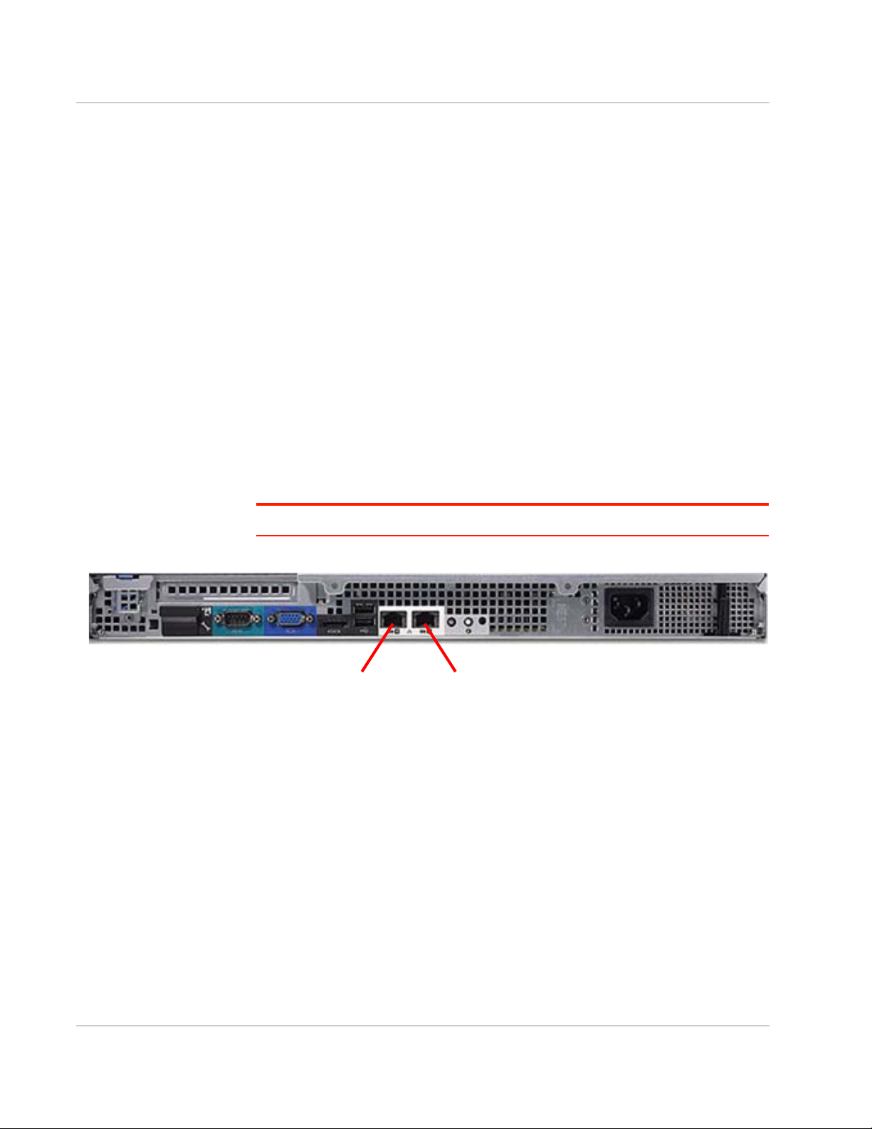
Port 1 Port 2
2. At a minimum, enable the following protocols and ports for the translated
address:
· IP Protocol ESP
· TCP/IP Port 2222
· UDP/IP 500
· UDP/IP 4500
If required by a customer security policy, the VPN between the AirLink gateway/
router and the ACM can be specified to route ALL traffic through the secure
connection. While there are some consequences with this approach, it does
provide the advantage of lock down so that all content is delivered to the
enterprise security environment where additional equipment can provide deeppacket inspection, anti-virus, and content filtering among other security services.
Ethernet Connections
Use Cat 5e Ethernet cabling with RJ45 connectors (not supplied) to connect the
ACM Ethernet ports to the network infrastructure.
• Connect Port 1 (GB1), the outside interface, to the network connected to the
enterprise firewall.
• Connect Port 2 (GB2), the inside interface, to the internal network.
Note: Any additional ports that may be present are unused.
Figure 2-1: Rear panel of ACM
Connecting to the ACM from an Inside Device
The ACM may be pre-configured with an inside network address and other
information as specified in Basic Configuration Requirements on page 52.
1. Establish a 10/100/1000 Mbps Ethernet connection between the inside
interface on Ethernet Port 2 of the ACM server and either an Ethernet switch
or a direct connection on a PC.
The default address and netmask of the Inside interface is 10.99.0.1/
255.255.255.0.
2. Use an SSH client tool (such as putty.exe) running on a test PC to open an
SSH session to port 2222 to the inside address.
Rev 3 Nov 17 10 4119855
Page 11

Installation
Note: Sierra Wireless can only provide remote technical support for the ACM if access to
Port 2222 is enabled on the public or private interface. If only private interface access is
available, an independent VPN access method must be provided.
Rev 3 Nov 17 11 4119855
Page 12

3: Configuration Overview
This chapter describes some common tasks performed by the ACM Administrator.
Logging In and Out
To log in to the ACM, use the default username (admin) and password (inmotion). For
example:
login as: admin
UNAUTHORIZED USE OF THIS SYSTEM IS PROHIBITED!
password:
WELCOME TO ACM!
This system is open-source software.
The exact distribution terms for each module
comprising the full system are described in the
individual files in /usr/share/doc/*/copyright.
Last login: Fri Apr 20 11:29:35 2016 from
xyz.com
3
admin@ACM:~$
Important: Sierra Wireless strongly recommends that you immediately change the Admin
password from the default value (“inmotion”) to prevent unauthorized use of the system. See
Admin Password on page 19 for details.
To log out of the ACM use the exit command:
admin@ACM:~$exit
Change to Configuration Mode
By default, the system will be in operational mode after logging in to the ACM, as
indicated by the ":~$" prompt.
To modify the ACM configuration, the system must first be changed to configuration
mode. To change to configuration mode, enter the configure command:
admin@ACM:~$ configure
The prompt for configuration mode will change to "#" as shown here:
admin@ACM#
Note: To change back to operational mode from configuration mode, use the “exit” command.
Rev 3 Nov 17 12 4119855
Page 13

Configuration Overview
Configuration Tree
The ACM configuration is stored in attributes and nodes:
• Attribute— Includes a name and a data value.
• Node—A container for one or more attributes. A node can also contain sub-
nodes to form a hierarchy of nodes.
Attributes and nodes are referred to as ‘statements’ when they are viewed from
the command line using the ‘show’ command.
The following snippet (from ‘show config’ output) is an example of an attribute,
node, and subnode:
local-ip 192.168.12.242 Attribute (name = ‘local-ip’, value = IP
address 192.168.12.242)
tunnel 1 { Node
esp-group 1 Attribute (name = ‘esp-group’, value = 1)
local { Sub-node
subnet 0.0.0.0/0 Attribute (name = ‘subnet’, value =
0.0.0.0/0)
}
}
Note: Nodes always have an enclosing pair of { } braces.
Manage Configuration Attributes
When the ACM server boots, its boot configuration is loaded into its running
configuration. While the server is running, configuration attributes are managed
using the commands shown in Table 3-1.
Table 3-1: Configuration Attribute Management Commands
Command Purpose Details
set Add or modify an attribute. See Add or Modify Attributes on page 14.
delete Delete an attribute. See Delete Attributes on page 15.
show
discard Remove all pending attribute changes.
commit
save
Display all pending attribute changes (add,
modify , delete).
Apply all pending attribute changes to the
currently running configuration.
Save the running configuration as the boot
configuration.
See Show Uncommitted Attribute Changes on
page 15.
See Discard Uncommitted Attribute Changes on
page 16.
See Apply Configuration on page 17
See Save Configuration on page 17
load
Load the ACM’s default configuration
attributes.
See Restore Default Configuration on page 18
Rev 3 Nov 17 13 4119855
Page 14

ACM Installation and Operations Guide
Note: Attribute changes (adding, modifying, deleting, lo ading defaults) do not take effect
on the ACM until they are first committed to the running configuration. After committing the
changes, they stay in effect until the server reboots. To keep them in effect across reboots,
they must be saved before the server reboots.
Add or Modify Attributes
To add a new attribute statement or modify an existing statement, use the set
command.
The following example demonstrates the set command being used to make the
following changes, and a snippet from the show command which displays the ‘+’
and ‘>’ symbols:
· change the hash method for an esp group’s “proposal 1” from “sha1” to
“md5”
· add a new “proposal 2” to the esp group
· add the encryption method for the new “proposal 2”
user@ACM1-Pro....duction# set vpn ipsec esp-group
espgroup1 proposal 1 hash md5
user@ACM1-Production# set vpn ipsec esp-group espgroup1
proposal 2 encryption aes256
user@ACM1-Production# show
...
esp-group espgroup1 {
compression enable
mode tunnel
pfs enable
proposal 1 {
encryption aes256
hash md5
}
+ proposal 2 {
+ encryption aes256
+ }
}
Rev 3 Nov 17 14 4119855
Page 15

Configuration Overview
Delete Attributes
To delete an attribute statement, use the delete command.
The following example demonstrates the delete command being used to make
the following change, and a snippet from the show command that displays the ‘-’
symbol:
· delete the hash method for an esp group’s “proposal 1”
user@ACM1-Production# delete vpn ipsec esp-group
espgroup1 proposal 1 hash
user@ACM1-Production# show
...
esp-group espgroup1 {
compression enable
mode tunnel
pfs enable
proposal 1 {
encryption aes256
- hash md5
}
}
....
Show Uncommitted Attribute Changes
To view pending attribute changes, use the show command.
When the command is used:
• the plus (+) symbol appears next to new attributes
• the greater than (>) symbol appears next to modified attributes
• the minus (-) symbol appears next to deleted attributes
The following example demonstrates a snippet from the show command which
displays:
· ‘>’ for an encryption method being modified
· ‘–’ for a hash method being deleted
· ‘+’ for a proposal being added
Rev 3 Nov 17 15 4119855
Page 16

ACM Installation and Operations Guide
user@ACM1-Production# show
...
esp-group espgroup1 {
compression enable
mode tunnel
pfs enable
proposal 1 {
> encryption aes256
- hash md5
}
+ proposal 2 {
+ encryption aes256
+ }
}
....
Discard Uncommitted Attribute Changes
To remove pending attribute changes so they cannot be committed to the running
configuration, use the discard command.
After discarding the configuration changes, the configuration reverts to the state it
was in prior to the changes and the symbol(s) (+, -, or >) located beside the
changed attribute statement(s) disappear.
The following example shows the discard command being used and a snippet
from the show command which displays:
· the original attribute values for proposal 1
· no proposal 2 (it is no longer being added)
user@ACM1-Production# show
...
esp-group espgroup1 {
compression enable
mode tunnel
pfs enable
proposal 1 {
encryption aes128
hash md5
}
}
....
Rev 3 Nov 17 16 4119855
Page 17

Configuration Overview
Apply Configuration
To apply changes to the ACM configuration, use the commit command.
After applying the configuration changes, the symbol(s) (+, -, or >) located beside
the changed attribute statement(s) disappear as shown in the example below.
Note: Committing applies the changes only to the currently running configuration. For the
committed changes to remain active after rebooting, they must be saved to the boot configuration as described in Save Configuration on page 17.
The following example shows the commit command being used when there
pending changes, and a snippet from the show command which shows that all
changes have been applied (there are no ‘+’, ‘>’, or ‘–’ symbols):
admin@ACM# commit
user@ACM1-Production# show
...
esp-group espgroup1 {
compression enable
mode tunnel
pfs enable
proposal 1 {
encryption aes256 changed from aes128
} hash attribute was deleted
proposal 2 { proposal 2 was added
encryption aes256
}
}
....
Save Configuration
Use the save command to save committed changes to the boot configuration so
that they remain active across reboots.
admin@ACM# save
Rev 3 Nov 17 17 4119855
Page 18

ACM Installation and Operations Guide
Restore Default Configuration
You can restore the ACM to its default configuration using the load, commit, and
save commands in configuration mode, as shown below.
Warning: This process COMPLETELY replaces the ACM’s current configuration, so
should be used only when absolutely necessary. DO NOT perform this via a remote login
session—if you do, you will lose your connection to the ACM when the configuration
(including the outside IP address) is replaced.
admin@ACM:~# load /opt/vyatta/etc/config.boot.default
admin@ACM:~# commit Commits changes to running
admin@ACM:~# save Saves changes as boot
configuration
configuration
Rev 3 Nov 17 18 4119855
Page 19

4: Basic Configuration
Admin Password
Important: Sierra Wireless strongly recommends that you immediately change the Admin
password from the default value to prevent unauthorized use of the system.
To change the default password of the admin account, use the following commands:
admin@ACM:~# set system login user admin authentication
plaintext-password <PASSWORD>
admin@ACM:~# commit
Note: Once the change is committed, the password is encrypted and is no longer available in
plain text.
Host Name
To change the ACM’s default hostname, use the following commands:
admin@ACM:~# set system host-name <HOST-NAME>
admin@ACM:~# commit
4
Domain Name
To change the ACM’s domain name, use the following commands:
admin@ACM:~# set system domain-name <DOMAIN-NAME>
admin@ACM:~# commit
OUTSIDE Interface IP Address
To change the IP address of the OUTSIDE interface, use the following commands:
admin@ACM:~# set interfaces ethernet eth0 address <WAN-IP-
ADDRESS/SUBNET-BITMASK>
admin@ACM:~# commit
Default Gateway
To change the default gateway, use the following commands:
admin@ACM:~# set system gateway-address <DEFAULT-GATEWAY-IP-
ADDRESS>
admin@ACM:~# commit
Rev 3 Nov 17 19 4119855
Page 20

ACM Installation and Operations Guide
INSIDE Interface IP Address
To change the IP address of the INSIDE interface, use the following commands.
Note: The default IP address must also be deleted as shown below.
admin@ACM:~# delete interfaces Ethernet eth1 address
10.99.0.1/24
admin@ACM:~# set interfaces ethernet eth1 address
<LAN-IP-ADDRESS/SUBNET-BITMASK>
admin@ACM:~# commit
INSIDE Routing Information IP Address
To specify how VPN traffic will be routed from the ACM to the enterprise network
application servers (only if intermediate routers exist) use the following
commands:
admin@ACM:~# set protocols static route <ENTERPRISE-
NETWORK/MASK> next-hop <NEXT-HOP-IP-ADDRESS>
DNS Server
To change the DNS server, use the following commands:
admin@ACM:~# set system name-server <DNS-IP-ADDRESS>
admin@ACM:~# commit
Rev 3 Nov 17 20 4119855
Page 21

5: ACM VPN Configuration
VPN Overview
A virtual private network (VPN) is a computer network that uses a public or private
telecommunication infrastructure to provide mobile systems, such as AirLink
gateways/routers, with secure access to the enterprise network.
An ACM provides the VPN server function to several AirLink device clients. This is
accomplished using TCP/IP standards and therefore routing plays a key role.
The mobile address space in all AirLink devices must be distinct from the enterprise
address space. Upstream routers must have appropriate forward and reverse routes.
Before proceeding with the VPN configuration, it is strongly recommended that a
complete network diagram be created that specifies address plans and routing
requirements.
Note: For details on configuring an AirLink gateway/router to use the VPN, refer to the device’s
Software Configuration Guide.
IPsec VPN
5
The ACM uses the strongSwan internet protocol security (IPsec) implementation for
securing communications by authenticating and encrypting each IP packet of a
communication session. IPsec also includes protocols for establishing mutual
authentication between agents at the beginning of the session and negotiation of
cryptographic keys to be used during the session.
The following parameters must be defined to be able to configure an IPsec VPN:
• Phase 1 and Phase 2 negotiation parameters:
· Encryption
· Hashing
· Key exchange method
• IDs for each side— IP address for the ACM, <PeerID> for the peer
• Source and destination IP address of the protected traffic
• Pre-shared secret or certificate
The ACM stores Phase 1 and Phase 2 parameters in groups (IKE for phase 1, and
ESP for phase 2) that can be reused in multiple VPN configurations.
ACM IKE/ESP Negotiation Parameters
Supported IKE (Phase 1)/ESP (Phase 2) negotiation parameters for non-FIPS and
FIPS ACMs are listed in the following table.
Rev 3 Nov 17 21 4119855
Page 22

ACM Installation and Operations Guide
Table 5-1: ACM IKE/ESP Parameter Support
ACM 1.6 (non-FIPS) ACM 1.6-FIPS
Type
IKE ESP IKE ESP
Encryption
aes128 Y Y Y Y
aes128ccm16 Y
aes128gcm16 Y
aes256 Y Y Y Y
aes256ccm16 Y
aes256gcm16 Y
3des Y Y
Hash
sha1 Y Y
sha2_256 Y Y Y Y
sha2_512 Y Y Y Y
md5 Y Y
none Y
DH Group
a
a
a
a
a
1
2 Y Y
5 Y Y
14 Y Y Y Y
15 Y Y Y Y
16 Y Y Y Y
17 Y Y
18 Y Y
19 Y Y
20 Y Y
21 Y Y
none Y
a. When aes128ccm16, aes128gcm16, aes256ccm16, or aes256gcm16 encryption is used,
hash must be none.
b. DH group ‘none’ is not recommended. For greater security, choose a supported ESP DH
group.
b
b
Y
Rev 3 Nov 17 22 4119855
Page 23

ACM VPN Configuration
IKE Group Configuration
The procedure for configuring IKE groups varies depending on the IKE version
being used.
To configure IKE groups for:
• oMG/MG90 routers, and NCP Client for Windows— See Configure IKE
Groups with MOBIKE (IKEv2) on page 23.
• AirLink gateways—See Configure IKE Groups with IKEv1 on page 24.
Configure IKE Groups with MOBIKE (IKEv2)
Note: Not all AirLink devices support IKEv2. IKEv2 is supported on oMG2000/500 and
MG90 routers—see Configure IKE Groups with IKEv1 on page 24 to configure IKE groups
for other AirLink devices.
When used on supported devices, the MOBIKE (IKEv2 Mobility and Multihoming)
protocol allows for fast, seamless VPN tunnel switching. Combining the oMG/
MG90’s intelligent WAN management with MOBIKE ensures the delivery of
secure and extremely high performance mobile communications.
To enable this switching feature, both the ACM and the peer (supported device)
must:
· Enable IKEv2 as the Key Exchange Mechanism
· Enable MOBIKE
Use the set vpn ipsec ike-group command to configure the IKE group parameters,
as described below.
Note: The attribute values used in the commands below are examples only; use values
that are appropriate for your configuration. Valid values for some IKE group configura tio ns
are described in Table 5-1 on page 22.
1. Configure the IKE group(s)—There can be more than one IKE group and
they can be called independently for different peers. The IKE group name can
be any string.
set vpn ipsec ike-group <IKE-GRP-NAME>
2. After configuring your IKE group(s), configure Dead Peer Detection (DPD):
a. For each group, enable DPD:
set vpn ipsec ike-group <IKE-GRP-NAME> dead-peer-
detection action clear
Important: Always enable DPD, and always use “action clear”—do NOT use
“action hold” or “action restart”.
Rev 3 Nov 17 23 4119855
Page 24

ACM Installation and Operations Guide
b. After enabling DPD on the IKE group(s), set the global DPD parameters
(these apply to DPD for all groups)— If not specified, default values are
used (30 second timeout, 3 retries):
set vpn ipsec ikev2-retransmit-timeout 15
set vpn ipsec ikev2-retransmit-tries 1
Note: Do not use the IKEv1 DPD configuration options “dead-peer-detection
interval” and “dead-peer detection timeout”—these are not supported in IKEv2.
3. Configure IKE Version and MOBIKE:
set vpn ipsec ike-group <IKE-GRP-NAME> ike-version
set vpn ipsec ike-group <IKE-GRP-NAME> mobike yes
4. Configure IKE transform set proposals (Note: There can be more than one
proposal.) See Table 5-1 on page 22 for supported parameter values:
set vpn ipsec ike-group <IKE-GRP-NAME> proposal 10
set vpn ipsec ike-group <IKE-GRP-NAME> proposal 10
set vpn ipsec ike-group <IKE-GRP-NAME> proposal 10
ikev2
dh-group <Dh_group_type>
encryption <Encrypt_type>
hash <Hash_type>
Configure IKE Groups with IKEv1
Note: oMG2000/500, MG90 and NCP Client for Windows should be configured for
IKEv2 —see Configure IKE Groups with MOBIKE (IKEv2) on page 23.
The following AirLink gateways support the IKEv1 protocol (IKEv2 is not
supported): LS, ES, GX, RV, and MP series.
Use the set vpn ipsec ike-group command to configure the IKE group parameters,
as described below.
Note: The attribute values used in the commands below are examples only; set the values
as appropriate for your configuration.
1. Configure the IKE group(s)—There can be more than one IKE group and
they can be called independently for different peers. The IKE group name can
be any string.
set vpn ipsec ike-group <IKE-GRP-NAME>
2. After configuring your IKE group(s), configure Dead Peer Detection (DPD) for
each group:
a. Enable DPD:
set vpn ipsec ike-group <IKE-GRP-NAME> dead-peer-
detection action clear
Rev 3 Nov 17 24 4119855
Page 25

ACM VPN Configuration
Important: Always enable DPD, and always use “action clear”—do NOT use
“action hold” or “action restart”.
b. Set the DPD parameters (these must be set for each group):
set vpn ipsec ike-group <IKE-GRP-NAME> dead-peer-
detection interval <Interval_seconds>
set vpn ipsec ike-group <IKE-GRP-NAME> dead-peer-
detection timeout <Timeout_seconds>
Note: Do not use the IKEv2 DPD configuration options “ikev2-retransmit-timeout”
and “ikev2-retransmit -tries”—these are not supported in IKEv1.
3. Configure the IKE version:
set vpn ipsec ike-group <IKE-GRP-NAME> ike-version
ikev1
4. Configure IKE transform set proposals (Note: There can be more than one
proposal.) See Table 5-1 on page 22 for supported parameter values:
set vpn ipsec ike-group <IKE-GRP-NAME> proposal 10
dh-group <Dh_group_type>
set vpn ipsec ike-group <IKE-GRP-NAME> proposal 10
encryption <Encrypt_type>
set vpn ipsec ike-group <IKE-GRP-NAME> proposal 10
hash <Hash_type>
ESP Group
Use the set vpn ipsec esp-group command to configure the ESP group
parameters, as described below.
Note: The attribute values used in the commands below are examples only; set the values
as appropriate for your configuration.
1. Configure the ESP Group(s)—There can be more than one ESP group and
they can be called independently for different peers. The <ESP-GRP-NAME>
can be any string.
set vpn ipsec esp-group <ESP-GRP-NAME>
2. After configuring your ESP Group(s), configure the following group parameters:
· Compression option:
set vpn ipsec esp-group <ESP-GRP-NAME> compression
disable
· ESP mode:
set vpn ipsec esp-group <ESP-GRP-NAME> mode tunnel
Rev 3 Nov 17 25 4119855
Page 26

ACM Installation and Operations Guide
· ESP transform set proposals (Note: There can be more than one proposal.)
See Table 5-1 on page 22 for supported parameter values:
set vpn ipsec esp-group <ESP-GRP-NAME> proposal 10
set vpn ipsec esp-group <ESP-GRP-NAME> proposal 10
· DH Group—The dh-group is required for AirLink gateways, optional for
NCP client peers, and must not be used for oMG/MG90 routers. See
Table 5-1 on page 22 for supported parameter values.
set vpn ipsec esp-group <ESP-GRP-NAME> proposal 10
VPN Peers
To provision tunnels for VPN peers (including supported AirLink gateways/
routers, and NCP Client for Windows), the ACM must be configured with the
peers’ IDs and other attributes.
Configure VPN Peer IDs
encryption <Encrypt_type>
hash <Hash_type>
dh-group <Dh_group_type>
To configure a VPN peer ID on the ACM, Use the following command:
set vpn ipsec site-to-site peer <PeerID>
where <PeerID> is one of the supported types described in Table 5-2 on page 27,
or “any”.
If the <PeerID> is:
• A supported Peer ID Type from Table 5-2—The ACM creates connections for
each peer, using different PSKs. This is the preferred method for oMG/MG90
routers and other AirLink gateways/routers, as it allows both the router/
gateway and the client devices of the router/gateway to use the VPN tunnels.
• “any”—The ACM creates Host2LAN connections with peers of the same type
(AirLink gateways/routers, or NCP clients) without having to specify their IDs
individually. All the peers will share the same pre-shared key (PSK).
This method is suitable for NCP clients since NCP operates on a host device
(laptop) and has not client devices that would require VPN access.
This method is not recommended for AirLink gateways/routers, as only the
router/gateway can use the VPN tunnel— its client devices cannot.
Rev 3 Nov 17 26 4119855
Page 27

ACM VPN Configuration
Table 5-2: VPN Peer ID Types
Peer Location in Software Peer ID Types
Note: Make sure to use the described formats to enter peer IDs in the peer’s sofware interface, and use
the same formats when entering the IDs on the ACM in the “set vpn ipsec site-to-site peer” command.
oMG/MG90 router WAN > VPNs > (Edit or
Add)
Field: Auth ID
AirLink gateway/
router (LS, ES,
GX, MP series)
NCP Client for
Windows
VPN > VPN#
Field: Peer Identity Type
Profiles > Identities
Field: Type
Recommended type:
• ESN—Router’s unique serial number (<ESN>)
Format: @<ESN>
Alternate types
• ip address
Format: <IP>
• custom:
Format: @<custom>
Recommended type:
• FQDN—Free-format string. User must ensure this is
a unique string.
Format: @<FQDN>
Alternate types:
• User FQDN—Free-format string. User must ensure
string is unique.
Format: @@<USER_FQDN>
• IP—Router’s IP address
Format: <IP>
Note: If FQDN or User FQDN is used, read Main/
Aggressive Mode Configuration on page 41 for additional
instructions.
Recommended type:
• Fully Qualified Domain Name
Format: @<FQDN>
Alternate types:
• IP Address
Format: <IP>
• Fully Qualified Username
Format: @@<User_FQDN>
• ASN1 Distinguished Name
Format: <ASN1 Dname>
(Note: Required if using certificate authentication.)
Not compatible with ACM:
• IP Subnet Address
• ASN1 Group Name
• Free string
Rev 3 Nov 17 27 4119855
Page 28

ACM Installation and Operations Guide
Configure VPN Peer Attributes
For each VPN peer, configure the following attributes:
Note: In these commands, replace <PeerID> with the peer ID type used by the ACM
(described in Configure VPN Peer IDs on page 26.
· PSK for the peer:
set vpn ipsec site-to-site peer <PeerID>
set vpn ipsec site-to-site peer <PeerID>
· IKE group for the peer:
set vpn ipsec site-to-site peer <PeerID> ike-group
· IP address of ACM WAN interface:
set vpn ipsec site-to-site peer <PeerID> local-ip
· Define at least one tunnel for this peer:
set vpn ipsec site-to-site peer <PeerID> tunnel 1
· ESP group for the peer's tunnel(s) (this must be set for each of the peer’s
tunnels—see previous point):
set vpn ipsec site-to-site peer <PeerID> tunnel 1
· The private subnet behind the ACM. In general, this is the enterprise LAN:
set vpn ipsec site-to-site peer <PeerID> tunnel 1
· Use the AirLink gateway/router's LAN-subnet as the remote subnet:
set vpn ipsec site-to-site peer <PeerID> tunnel 1
authentication mode pre-shared-secret
authentication pre-shared-secret <PRESHARED-KEY>
<IKE-GRP-NAME>
<WAN-IP-ADDRESS>
esp-group <ESP-GRP-NAME>
local subnet <LAN-SUBNET/SUBNET-BITMASK>
remote subnet <oMG-LAN-SUBNET/SUBNET-BITMASK>
VPN ID
When the ACM is located within a DMZ, behind an external firewall, the VPN
connection is set up to an external IP address that is translated to an internal
private address (the outside interface of the ACM). To specifically identify the peer
of the connection, the peer must be configured with a Server ID and this ID must
match that of the ACM.
The default behavior in the ACM is to use the local IP of the outside interface
address as this ID.
However the ID can be explicitly assigned another value. This is a good practice
as it allows the ACM internal IP address to be re-assigned without requiring the
peers to also be reconfigured in the event that the enterprise network is rearranged after deployment.
Configure the ACM ID:
set vpn ipsec site-to-site peer any authentication id
<IDENTITY-STRING>
Rev 3 Nov 17 28 4119855
Page 29

ACM VPN Configuration
Certificate Management and Revocation
The ACM can utilize a system of public key and certificates to allow or deny
access to client devices. For a client device to connect to the ACM, its certificate
must be signed by the same CA authority and must have the same cacert.pem
certificate file that the ACM has. These certificates and their associated keys are
issued by a certificate authority (CA).
ACM supports the following certificate types:
• RSA 2048 bits
• RSA 3072 bits
• ECDSA 224 bits (Note: Not supported by oMG/ MG90)
To provision the ACM with certificates:
1. Copy the certificates into the directory: /config/auth on the ACM. To do so, log
in to the server where the certificate files exist and invoke the following
commands:
[user@server ~]$ scp -P 2222 <ca_cert_file_name>
admin@<ACM-IP>:/config/auth
[user@server ~]$ scp -P 2222 <ACM_cert_file_name>
admin@<ACM-IP>:/config/auth
[user@server ~]$ scp -P 2222 <ACM_key_file_name>
admin@<ACM-IP>:/config/auth
2. Provision the CA certificates:
set vpn ipsec x509 ca <ca_cert_name> ca-cert-file
/config/auth/<ca_cert_file_name>
set vpn ipsec x509 ca <ca_cert_name> ca-cert-type
<RSA | ECDSA>
3. Provision the host certificate:
set vpn ipsec x509 host <host_cert_name> cert-file
/config/auth/<ACM_cert_file_name>
set vpn ipsec x509 host <host_cert_name> cert-type
<RSA | ECDSA>
set vpn ipsec x509 host <host_cert_name> key file
/config/auth/<ACM_key_file_name>
set vpn ipsec x509 host <host_cert_name> key type
<RSA | ECDSA>
As part of this security system, the ACM also supports a certificate revocation list
(CRL) that explicitly lists the certificates of devices who should not be granted
access to the ACM. The certificates listed can be either revoked (denied access)
or in a "hold" state meaning they have yet to be approved and are thus
temporarily invalid.
To use the CRL on the ACM:
1. Copy the CRL file into the directory: /config/auth on the ACM. To do so, log in
to the server where the CRL file exists and invoke the following command:
[user@server ~]$ scp -P 2222 <crl_file> admin@<ACM-IP>:/
config/auth
Rev 3 Nov 17 29 4119855
Page 30

ACM Installation and Operations Guide
2. Configure the CRL on the ACM:
set vpn ipsec x509 ca <ca_cert_name> crl-file /config/
auth/<crl_file>
Configuring for NCP Client for Windows
The following subsections describe the server-side settings and configuration
changes necessary to allow connections from NCP Client for Windows. For clientside configuration details, refer to the AirLink Connection Manager Configuration
Guide for NCP Client.
Assigning a Virtual IP Address from the Pool
To allow NCP Client VPN connections, the ACM must assign a Virtual IP address
from its IP address pool using either of the following methods:
• Certificates—Use the following commands:
set vpn ipsec x509 ca MyCA ca-cert-file /config/auth/
<cacert.pem>
set vpn ipsec x509 ca MyCA ca-cert-type RSA
set vpn ipsec x509 host <ACM_host-cert_name> cert-file
/config/auth/<ACM_host_cert.pem>
set vpn ipsec x509 host <ACM_host-cert_name> cert-type
RSA
set vpn ipsec x509 host <ACM_host-cert_name> key file
/config/auth/<ACM_host_cert.pem>
set vpn ipsec x509 host <ACM_host-cert_name> key type RSA
• Pre-shared keys—Use the following commands:
Note: Pre-shared keys are not recommended for NCP Client because all clients must
share the same PSK.
set vpn ipsec site-to-site peer any authentication mode
pre-shared-secret
set vpn ipsec site-to-site peer any authentication
pre-shared-secret <your password>
set vpn ipsec site-to-site peer any auto-firewall yes
set vpn ipsec site-to-site peer any ike-group
<ike group name>
set vpn ipsec site-to-site peer any local-ip <ACM IP>
set vpn ipsec site-to-site peer any tunnel 1 esp-group
<esp group name>
set vpn ipsec site-to-site peer any tunnel 1 local subnet
<ACM inside subnet or 0.0.0.0/0>
set vpn ipsec site-to-site peer any tunnel 1 remote-
source-ip <the IP pool>
Rev 3 Nov 17 30 4119855
Page 31

ACM VPN Configuration
To provision the tunnel, use the following commands:
set vpn ipsec site-to-site peer any authentication mode
x509
set vpn ipsec site-to-site peer any authentication x509
ca MyCA
set vpn ipsec site-to-site peer any authentication x509
host MyHostCert
set vpn ipsec site-to-site peer any authentication id
"C=CA, ST=BC, O=InMotion, OU=eng, CN=<your common
name>"
set vpn ipsec site-to-site peer any autofirewall yes
set vpn ipsec site-to-site peer any ike-group <groupname>
set vpn ipsec site-to-site peer any local-ip <ACM IP>
set vpn ipsec site-to-site peer any tunnel 1 esp-group
<groupname>
set vpn ipsec site-to-site peer any tunnel 1 local subnet
<0.0.0.0/0 or enterprise subnet>
set vpn ipsec site-to-site peer any tunnel 1 remote-
source-ip <the IP pool>
EAP Authentication
Important: IPSec VPN IKEv2 EAP authentication is supported only for NCP Client for
Windows connecting with non-FIPS ACMs. It is NOT supported on AirLink gateways/
routers.
If using a non-FIPS ACM, EAP authentication can optionally be used for NCP
Client for Windows.
ACM 1.6 and above support using EAP for IKEv2 to authenticate the client to the
server with EAP-TLS and EAP-MD5.
• If EAP authentication is selected, then the NCP Client uses a username and
password (or a certificate) to authenticate itself to a RADIUS server inside the
enterprise network.
• If EAP is not used, then the IKEv2 authentication mode uses a PSK or certificate.
Note: The ACM always authenticates itself to the NCP Client using a pre-shared-key or
certificate.
The following describe the server-side steps to configure EAP authentication. For
client-side configuration, refer to the AirLink Connection Manager Configuration
Guide for NCP Client.
Rev 3 Nov 17 31 4119855
Page 32

ACM Installation and Operations Guide
Provisioning EAP on the ACM
To provision EAP on the ACM:
1. Run the following commands on the ACM to configure the RADIUS server
connection:
set vpn ipsec eap-radius-server address <IP address of
RADIUS sever>
set vpn ipsec eap-radius-server secret <password>
set vpn ipsec eap-radius-server port <port on RADIUS
server>
2. Enable EAP on the connection using the following command:
set vpn ipsec site-to-site peer any authentication eap
yes
Configuring the RADIUS Server Settings
See RADIUS Server Settings on page 53 for steps on installing and configuring a
RADIUS server.
ACM Server Protocols
ACM supports two server protocols that are intended to ensure ACM services
remain available in case of server failures (both protocols) or heavy loads (High
Availability Configuration only).
These protocols are:
• Virtual Router Redundancy Protocol (VRRP) on page 32—ACM server appli-
ances (two or more) are clustered together with a master server providing all
services and the other appliances available to take the master’s place if it
fails.
• High Availability Configuration—For very large customers (many client
devices), each client device (oMG/ MG90 router) is assigned to a random
ACM server from a pool of servers (load balancing). If a server fails, the client
devices that are connected to that server request assignment to another
server from the pool (server redundancy). For configuration details, refer to
the AirLink Connection Manager High Availability Setup Guide.
Virtual Router Redundancy Protocol (VRRP)
Overview of VRRP
The ACM technology utilizes virtual router redundancy protocol (VRRP) to ensure
that services are available in the event that an ACM goes down. VRRP requires
two or more physical ACMs and allows this cluster of ACMs to act as one virtual
ACM. The group of physical ACMs which make up this cluster is known as a
VRRP Group. The physical ACMs in the group multicast packets to notify each
other that each is still alive. If the current master ACM stops broadcasting, then a
backup ACM in the VRRP group will take over as the master.
Rev 3 Nov 17 32 4119855
Page 33

ACM VPN Configuration
Virtual IP:
10.10 . 12.13
Outside
Subnet
Master ACM
VRRP Group: 99
Priority: 7
ACM
VRRP Group: 99
Priority: 5
Virtual IP:
10.11.11.19
Inside
Subnet
Inside
Interface
Inside
Interface
Outside
Interfac e
Outside
Interfac e
InternetEnterprise
Sierra Wire le ss
AirLink
gateway/router
Devices accessing an ACM from outside connect to a virtual IP address and
therefore have no knowledge of which physical ACM they are connected to. For a
cluster of ACMs to operate under VRRP:
• Each ACM must be assigned the same VRRP group number
• Each ACM must be mapped to the same virtual IP address
• Each ACM must be on the same subnet
Within a VRRP group, the ACM with the highest priority is elected as the
"master", which is the ACM that devices connect to, as shown in Figure 5-1.
Figure 5-1: A master ACM is the ACM with the highest priority
In the event that this master goes down, the ACM with the next highest priority will
be elected as the new master, and all ACMs are notified, as shown in Figure 5-2
on page 34. If two ACMs have the same priority, the device with the higher IP
address will be elected as the master (note that during startup, this conflict is
resolved by electing the device which becomes active first).
Rev 3 Nov 17 33 4119855
Page 34

ACM Installation and Operations Guide
Outside
Interface
Virtual IP:
10.10.12.13
Outside
Subnet
Master ACM
VRRP Group: 99
Priority : 7
Master ACM
VRRP Group: 99
Priority : 5
Failed
New Master elected
Internet
Virtual IP:
10.11.11.19
Inside
Subnet
Enterprise
Inside
Interface
Inside
Interface
Outside
Interface
Sierra Wire less
AirLink
gateway/router
Virtual IP:
10.10.12.13
Outside
Subnet
(former Master) ACM
VRRP Group: 99
Priority: 5
Failed &
Removed
(New) Master ACM
VRRP Group: 99
Priority: 6
Newly added
ACM
Pre-empted by new ACM
Internet
Virtual IP:
10.11.11.19
Inside
Subnet
Enterprise
Outside
Interface
Outside
Interface
Inside
Interface
Inside
Interface
Sierra Wireless
AirLink
gateway/router
Figure 5-2: The next highest priority ACM will become the master upon a failure
VRRP has a feature called "pre-emption" that allows for automatic election of a
new, higher priority ACM. This is useful in the situation where an ACM has been
elected as the master after the failure of a high priority ACM, and then a new
higher priority ACM is added. In this case, the newly added ACM will
automatically "pre-empt" the current, lower priority master and take over as the
new master, as shown in Figure 5-3.
Rev 3 Nov 17 34 4119855
Figure 5-3: Pre-emption allows a new, higher-priority ACM to take over as the master
Page 35

ACM VPN Configuration
Virtual I P :
10.10.12.13
Outside
Subnet
(Former Master) A CM
VRRP Group: 101
Priority: 7
(New) Master ACM
VRRP Group: 101
Priority: 5
Sync Group
Sync Group
Failure
New Master ACM elected
Internet
Virtual IP:
10.11.11.19
Inside
Subnet
Enterprise
Outside
Interface
Outside
Interface
Inside
Interface
Inside
Interface
Sierra Wireless
AirLink
gateway/router
VRRP allows the failure of inside interfaces on an ACM to trigger a fail over to a
backup ACM through a feature called "sync groups". For example, if the inside
interface on a master ACM fails, this will cause the master ACM and its outside
interface to fail as well. The backup ACM would then be elected as the master, as
shown in Figure 5-4 on page 35.
Important: Sync groups must be used when configuring VRRP.
Figure 5-4: A Sync Group elects a new master ACM upon the failure of an inside interface
Note: If VRRP is enabled with the RFC compliant option, ensure a firewall is positioned on
the outside of the ACMs to protect them.
Configuring the Master and Backup ACMs
To configure the master ACM and each backup ACM, do the following for each
ACM:
1. Create the VRRP configuration node for eth0 to enable VRRP on that
interface and assign the VRRP group (Note: All of the ACMs must use the
same group):
set interfaces ethernet eth0 vrrp vrrp-group
2. Specify the virtual IP address of the VRRP group:
set interfaces ethernet eth0 vrrp vrrp-group
Rev 3 Nov 17 35 4119855
<VRRP GROUP #>
<VRRP GROUP #> virtual-address <VIRTUAL OUTSIDEIPADDRESS/SUBNET>
Page 36

ACM Installation and Operations Guide
3. Enable pre-emption:
set interfaces ethernet eth0 vrrp vrrp-group
<VRRP GROUP #> preempt true
4. Set the priority of this ACM:
set interfaces ethernet eth0 vrrp vrrp-group
<VRRP GROUP #> priority <PRIORITY #>
Important: Make sure to set a higher priority for the master ACM than the priorities for all
backup ACMs.
5. Commit the configuration:
commit
6. Display the configuration (optional):
show interfaces ethernet eth0 vrrp
Configuring the Master and Backup ACMs with a Sync
Group
Sync Groups are identified by a unique string that is configured using the steps
below (for example, "ALPHA", "MyGROUP" etc).
To configure the master ACM and each backup ACM with a sync group, do the
following for each ACM:
1. Add the sync group configuration to the existing configuration for a VRRP
group on eth0:
set interfaces ethernet eth0 vrrp vrrp-group
<VRRP GROUP #> sync-group <SYNC GROUP NAME>
2. Display the VRRP configuration on eth0 (optional):
show interfaces ethernet eth0 vrrp
3. Create the VRRP configuration node for eth1 on the ACM to enable VRRP on
that interface; assign the VRRP group:
set interfaces ethernet eth1 vrrp vrrp-group
<VRRP GROUP #>
4. Specify the virtual address of the VRRP group:
set interfaces ethernet eth1 vrrp vrrp-group
<VRRP GROUP #> virtual-address <VIRTUAL INSIDEIPADDRESS/SUBNET>
5. Enable preemption:
set interfaces ethernet eth1 vrrp vrrp-group
<VRRP GROUP #> preempt true
6. Set the priority of this ACM— Make sure to set a higher priority for the master
ACM than the priorities for all backup ACMs:
set interfaces ethernet eth1 vrrp vrrp-group
<VRRP GROUP #> priority <PRIORITY #>
Rev 3 Nov 17 36 4119855
Page 37

ACM VPN Configuration
Important: Make sure to set a higher priority for the master ACM than the priorities for all
backup ACMs.
7. Add the VRRP group on eth1 to the sync group:
set interfaces ethernet eth1 vrrp vrrp-group
<VRRP GROUP #> sync-group <SYNC GROUP NAME>
8. Commit the configuration:
commit
9. Display the configuration (optional):
show interfaces ethernet eth1 vrrp
AirLink oMG/MG90 Router Support
This section applies to AirLink oMG2000/500 and MG90. For AirLink LS, ES, and
GX series gateways, and MP series routers, see AirLink Gateway/Router
Support—LS, ES, GX, MP Series on page 38.
oMG/MG90 IKE/ESP Negotiation Parameters
When using oMG/MG90 peers with the ACM, some limitations apply:
• Some ACM features are not supported by oMG/MG90.
• Some oMG/MG90 features are not supported by ACM.
The following table describes these limitations and the restrictions these place on
ACM configuration and oMG/ MG90 configuration.
Table 5-3: oMG/ M G90 IKE/ESP Parameter Support
ACM 1.6 oMG MG90
non-FIPS FIPS non-FIPS FIPS non-FIPS FIPS
Type
Encryption
aes128 Y Y Y Y Y Y Y Y Y Y Y
aes128ccm16 Y
aes128gcm16 Y
aes256 Y Y Y Y Y Y Y Y Y Y
aes256ccm16 Y
aes256gcm16 Y
IKE ESP IKE ESP IKE ESP IKE ESP IKE ESP IKE ES P
b
b
b
b
Y Y
a
Setup
Requirements
b
Y
b
b
Y
b
Y
3des Y Y Y Y Y Y
Rev 3 Nov 17 37 4119855
Page 38

ACM Installation and Operations Guide
Table 5-3: oMG/ M G90 IKE/ESP Parameter Support (Continued)
ACM 1.6 oMG MG90
non-FIPS FIPS non-FIPS FIPS non-FIPS FIPS
Type
Hash
sha1 Y Y Y Y Y Y
sha2_256 Y Y Y Y Y Y Y Y Y Y Y
sha2_512 Y Y Y Y Y Y Y Y Y Y
md5 Y Y Y Y Y Y
none Y
DH Group
1
2 Y Y Y Y 4.1.x
5 Y Y Y Y 4.1.x
14 Y Y Y Y Y Y 4.1.xcY Y
15 Y Y Y Y Y Y 4.1.xcY Y
16 Y Y Y Y Y Y 4.1.xcY Y
17 Y Y Y Y 4.1.x
18 Y Y Y 4.1.x
IKE ESP IKE ESP IKE ESP IKE ESP IKE ESP IKE ES P
b
Y Y
c
c
c
c
a
Setup
Requirements
b
On the ACM:
• Do not
configure oMG
peers to use
DH group 18.
• Do not
configure dhgroup in espgroup
proposals.
19 Y Y Y Y Y
20 Y Y Y Y
21 Y Y Y Y
none Y
a. Pending release Q3 2017.
b. When aes128ccm16, aes128gcm16, aes256ccm16, or aes256gcm16 encryption is used, hash must be none.
c. ESP DH group support is available in 4.1.x. In versions <4.1, the DH group for ESP is inherited from IKE, and after a re-key, no
DH group is applied to the ESP.
d. DH group ‘none’ is not recommended. For greater security, choose a supported ESP DH group.
d
d
Y
Y Y Y
d
AirLink Gateway/Router Support—LS, ES, GX, MP Series
This section applies to AirLink LS, ES, and GX series gateways, and MP series
routers. For AirLink oMG2000/ 500 and MG90 routers, see AirLink oMG/MG90
Router Support on page 37.
Rev 3 Nov 17 38 4119855
Page 39

ACM VPN Configuration
ACM/AirLink (LS, ES, GX, MP Series) Setup Requirements
When using AirLink gateways/ routers (other than oMG and MG90) with the ACM,
some limitations apply:
• Some ACM features are not supported by AirLink devices.
• Some AirLink features are not supported by ACM.
The following tables describe these limitations and the restrictions these place on
ACM configuration and AirLink configuration (using ACEmanager).
Table 5-4: AirLink IKE/ESP Parameter Support
ACM 1.6 AirLink
Type IKE ESP IKE ESP Setup Requirements
Encryption
aes128 Y Y Y Y On the AirLink device:
aes128ccm16
aes128gcm16
• Use only AES128, AES256, or
3DES—the ACM does not support
DES or None
aes256 Y Y Y Y
aes256ccm16
aes256gcm16
3des Y Y Y Y
des
none Y Y
Hash
sha1 Y Y Y Y On the AirLink device and the ACM:
sha2_256 Y Y
sha2_512 Y Y
md5 Y Y Y Y
none Y Y
• Configure the peer to use only MD5 or
SHA1.
Rev 3 Nov 17 39 4119855
Page 40

ACM Installation and Operations Guide
Table 5-4: AirLink IKE/ESP Parameter Support (Continued)
Type IKE ESP IKE ESP Setup Requirements
DH Group
1 Y Y On the AirLink device:
2 Y Y Y Y
5 Y Y Y Y
14 Y Y
15 Y Y
16 Y Y
17 Y Y
18 Y Y
19
20
ACM 1.6 AirLink
• Configure the device to use only DH2
or DH5.
On the ACM:
• Configure the peer to use only DH2 or
DH5.
• Make sure the dh-group is configured
in esp-group proposals
21
none Y Y
Table 5-5: Additional ACM/ AirL ink Setup Requirements
Feature Support limitation Setup Requirement
Certificates AirLink devices do not
support certificates
DNS Load Balancing AirLink devices do not
support load balancing
On the ACM, configure the
peer to use PSK only.
n/a
‘Single Address’ Type for Host2LAN Connection
Typically, AirLink gateways/routers are configured to use LAN2LAN VPN
connections, which allows the AirLink device and its client devices to access the
VPN tunnel.
However, if the AirLink device must be configured to use a Host2LAN VPN
connection (where only the AirLink device can access the tunnel), the device
must be configured to use the “Single Address” local address type, and the
address must match the device’s USB IP address or Ethernet IP address to
establish a tunnel to the ACM.
1. Check and update (if necessary) the IP address that will be used:
· USB IP address:
i. In ACEmanager, select LAN > USB.
ii. In USB Device Mode, make sure USBNET is selected.
Rev 3 Nov 17 40 4119855
Page 41

ACM VPN Configuration
iii. In Device USB IP, enter the AirLink device’s IP address.
The default address is 192.168.14.31. If the gateway is part of a fleet,
each gateway must be configured with a unique address—modify the
third octet for each device (e.g. 192.168.14.31 for the first gateway,
192.168.15.31 for the second, etc.)
iv. Click Apply.
· Ethernet IP address:
i. In ACEmanager, select LAN > Ethernet.
ii. In Device IP, enter the AirLink device’s IP address.
The default address is 192.168.13.31. If the gateway is part of a fleet,
each gateway must be configured with a unique address—modify the
third octet for each device (e.g. 192.168.13.31 for the first gateway,
192.168.14.31 for the second, etc.)
iii. Click Apply.
2. Select VPN > [VPN#].
a. In VPN 1 type, select IPsec Tunnel.
b. In Local Address Type, select “Single Address” from the drop-down list.
c. In Local Address, enter the IP address (USB or Ethernet) set in step 1.
d. Click Apply.
e. Click Reboot.
Main/Aggressive Mode Configuration
AirLink gateways/ routers support IKEv1 in main mode and aggressive mode.
When determining whether to configure an AirLink device for aggressive mode,
consider the following use cases:
Table 5-6: Main/Aggressive Mode Use Cases
Main Mode Main Mode + FQDN Aggressive Mode
• Secure
• Available only if ID Authen-
tication ID T ype is Stat ic IP
address
For each device configured to use aggressive mode, configure the ACM using:
set vpn ipsec site-to-site peer <PeerID> authentication
(See Table 5-2 on page 27 for supported <PeerID> types and formats.)
• Secure
• Best option if Static IP
address is not available.
• All gateways/routers use the
same PSK—If PSK is
compromised, all gateways/
routers in fleet must be
configured with a new PSK.
aggressivemode yes
• Not secure, PSK transmitted
unencrypted in Phase 1.
• Gateways can use different
PSKs
• If user accepts the security risk,
this option allows for faster
setup.
Rev 3 Nov 17 41 4119855
Page 42

ACM Installation and Operations Guide
NCP Client for Windows
ACM supports VPN connections from mobile devices using NCP Client for
Windows.
For NCP Client product support, refer to https://www.ncp-e.com.
NCP Client/ACM Setup Requirements
When using NCP Client peers with the ACM, some limitations apply:
• Some ACM features are not supported by NCP.
• Some NCP features are not supported by ACM.
The following table describes these limitations and the restrictions these place on
ACM configuration and NCP configuration.
Table 5-7: NCP Client IKE/ESP Parameter Support
ACM 1.6 NCP Client
non-FIPS FIPS non-FIPS FIPS
Type
Encryption
aes128 Y Y Y Y Y Y Y Y On the NCP Client:
aes128ccm16 Y
aes128gcm16 Y Y
aes256 Y Y Y Y Y Y Y Y
aes256ccm16 Y
aes256gcm16 Y Y
3des Y Y Y Y
des Y Y
Hash
sha1 Y Y Y Y
sha2_256 Y Y Y Y Y Y Y Y
sha2_512 Y Y Y Y Y Y Y Y
md5 Y Y Y Y
none Y
IKE ESP IKE ESP IKE ESP IKE ESP
Setup Requirements
• Use only AES128,
AES256, or 3DES—the
ACM does not support
DES
Rev 3 Nov 17 42 4119855
Page 43

ACM VPN Configuration
Table 5-7: NCP Client IKE/ESP Parameter Support (Continued)
ACM 1.6 NCP Client
non-FIPS FIPS non-FIPS FIPS
Type
DH Group
1 Y Y On the NCP Client:
2 Y Y Y Y
5 Y Y Y Y
14 Y Y Y Y Y Y Y Y
15 Y Y Y Y Y Y Y Y
16 Y Y Y Y Y Y Y Y
17 Y Y Y Y
18 Y Y Y Y
19 Y Y Y Y
20 Y Y Y Y
21 Y Y Y Y
none Y Y Y
IKE ESP IKE ESP IKE ESP IKE ESP
Setup Requirements
• Configure the device to
use any supported group
except DH1.
Table 5-8: Additional ACM/ NCP Client Setup Requirements
Feature Support limitation Setup Requirement
PFS ACM always uses PFS On the NCP Client, enable PFS.
Authentication For certificate
authentication, ACM
supports only the NCP ID
type “ASN1 Distinguished
Name”.
Certificates NCP may not support RSA-
3072.
Peer ID Type ACM supports:
• Fully Qualified Domain
Name
• IP Address
• Fully Qualified
Username
• ASN1 Distinguished
Name
On the NCP Client, configure
the ID type as “ASN1
Distinguished Name”.
Onthe NCP Client, configure to
use RSA-2048. If RSA -3072 is
attempted and fails, change to
one of the other options.
On the NCP Client, use one of:
• FQDN (recommended)
• ASN1 Distinguished Name
(required for certificate
authentication)
• IP Address
• Fully Qualified Username
Rev 3 Nov 17 43 4119855
Page 44

6: Troubleshooting
Upgrading to ACM 1.6
When upgrading to ACM 1.6, you must enter a name to store the image file.
To upgrade to ACM 1.6 from an earlier version:
1. Enter the following command:
add system image <imagefile>
(where <imagefile> is the pathname of an ISO file (such as “ACM-1.6.0-
20160719.1.iso) on the ACM or a URL to a remote file)
2. When prompted to enter a name for the image, use the version portion of the
<imagefile> name (e.g. “1.6.0-rc3-20160719.1”), or an alternate name of your
choice, and press Enter to continue.
Note: The name must contain only letters, digits, and special characters (‘-’, ‘+’, ‘.’,
‘_’).
Example (bolded text represents your input):
admin@ACM:~$ add system image ACM-1.6.0-20160719.1.iso
Checking MD5 checksums of files on the ISO image...OK.
...
What would you like to name this image? []: 1.6.0-20160719.1
...
6
View VPN Configuration Details
Use the following commands to view various aspects of the VPN configuration.
IKE Process Status
To view the status of the IKE process:
admin@ACM: show vpn ike status
Charon Process Running
Charon PID: 14981
Rev 3 Nov 17 44 4119855
Page 45

Troubleshooting
IKE Security Associations
To view IKE security associations:
admin@ACM: show vpn ike sa
Peer ID / IP Local ID / IP
------------ ------------CN=omg_valid1 192.168.4.22
State Encrypt Hash D-H Grp NAT-T A-Time L-Time
----- ------- ---- ------- ----- ------ ----- up aes256 sha1 5 no n/a 0
Peer ID / IP Local ID / IP
------------ -------------
192.100.1.2 192.168.4.22
State Encrypt Hash D-H Grp NAT-T A-Time L-Time
----- ------- ---- ------- ----- ------ ----- up aes256 sha1 5 yes 15942 28800
IPsec Process Status
To view the status of the IPsec process:
admin@ACM: show vpn ipsec status
Charon Process Running PID: 14981
1 Active IPsec Tunnels
IPsec Interfaces :
eth0 (192.168.4.10)
eth1 (no IP on interface statically configured
as local-ip for any VPN peer)
Rev 3 Nov 17 45 4119855
Page 46

ACM Installation and Operations Guide
IPsec Security Associations
To view IPsec security associations:
admin@ACM: show vpn ipsec sa
Peer ID / IP Local ID / IP
------------ -------------
Peer ID / IP Local ID / IP
------------ ------------CN=omg_revoked1 192.168.4.22
Tunnel State Bytes Out/In Encrypt Hash NAT-T A-Time L-
Time Proto
------ ----- ------------ ------- ---- ----- ------ -
----- -----
7 down n/a n/a n/a no n/a 0
all
Peer ID / IP Local ID / IP
------------ ------------CN=omg_valid1 192.168.4.22
Tunnel State Bytes Out/In Encrypt Hash NAT-T A-Time L-
Time Proto
------ ----- ------------ ------- ---- ----- ------ -
----- -----
1 up 71.4K/71.8K aes128 sha1 no n/a 0
all
Peer ID / IP Local ID / IP
------------ -------------
192.100.1.2 192.168.4.22
Tunnel State Bytes Out/In Encrypt Hash NAT-T A-Time L-
Time Proto
------ ----- ------------ ------- ---- ----- ------ -
----- -----
2 up 233.6K/232.0K aes128 sha1 yes 2152
3600 all
Rev 3 Nov 17 46 4119855
Page 47

Troubleshooting
IPsec IP Pool Status
To view IPsec security associations:
admin@ACM: show vpn ipsec ip-pool
Leases in pool '192.168.114.0/24', usage: 3/254, 0 online
192.168.114.2 offline 'TestNCP2'
192.168.114.1 offline 'peapuser'
192.168.114.3 offline 'C=CA, ST=BC, O=InMotion, OU=eng,
CN=Ttest1'
Leases in pool '10.101.1.0/24', usage: 0/254, 0 online
no matching leases found
Debug Information
To view more detailed information when you are troubleshooting, use the show
vpn debug command (for all debug information) or the show vpn debug peer
<PeerID> command (to debug a specific peer):
admin@ACM: show vpn debug
Status of IKE charon daemon (strongSwan 5.3.2, Linux
3.0.23-1-586-vyatta, i686):
uptime: 3 days, since Nov 27 15:26:05 2015
malloc: sbrk 409600, mmap 0, used 273032, free 136568
worker threads: 11 of 16 idle, 5/0/0/0 working, job
queue: 0/0/0/0, scheduled: 0
loaded plugins: charon ldap aes rc2 sha1 sha2 md5 random
nonce x509 revocation constraints pubkey pkcs1
pkcs7 pkcs8 pkcs12 sshkey pem openssl fips-prf
agent xcbc cmac hmac ctr ccm gcm curl attr kernelnetlink resolve socket-default stroke updown eapidentity eap-aka eap-md5 eap-gtc eap-mschapv2 eapradius eap-tls eap-ttls eap-tnc xauth-generic
xauth-eap tnc-tnccs error-notify certexpire
addrblock
Virtual IP pools (size/online/offline):
172.18.114.0/24: 254/1/1
Listening IP addresses:
10.1.65.114
192.168.114.1
10.1.97.114
Connections:
peer-any-tunnel-1: 10.1.65.114...%any IKEv2
peer-any-tunnel-1: local: [10.1.65.114] uses pre-
shared key authentication
Rev 3 Nov 17 47 4119855
Page 48

ACM Installation and Operations Guide
peer-any-tunnel-1: remote: uses EAP_RADIUS
authentication with EAP identity '%any'
peer-any-tunnel-1: child: 192.168.114.0/24 === dynamic
TUNNEL
Security Associations (1 up, 0 connecting):
peer-any-tunnel-1[19]: ESTABLISHED 72 seconds ago,
10.1.65.114[10.1.65.114]...10.1.65.66[]
peer-any-tunnel-1[19]: IKEv2 SPIs: 89f07750b7bb0459_i
6cd14c493a517903_r*, rekeying disabled
peer-any-tunnel-1[19]: IKE proposal: AES_CBC_256/
HMAC_SHA1_96/PRF_HMAC_SHA1/MODP_1536
peer-any-tunnel-1{30}: INSTALLED, TUNNEL, reqid 5, ESP
in UDP SPIs: c85fcdca_i 25b11ae1_o
peer-any-tunnel-1{30}: AES_CBC_256/HMAC_SHA1_96, 384
bytes_i (8 pkts, 2s ago), 384 bytes_o (8 pkts, 2s
ago), rekeying disabled
peer-any-tunnel-1{30}: 192.168.114.0/24 ===
172.18.114.2/32
View VRRP Configuration Details
To view VRRP configuration details on the master ACM or backup ACM, use the
show vrrp command with appropriate parameters, as shown below.
On the master:
admin@ACM:~$ show vrrp interface eth0
Physical interface: eth0, Source Address 192.168.3.112
Interface state: up, Group 99, State: master
Priority: 250, Advertisement interval: 1,
Authentication type: none
Preempt: true, VIP count: 1, VIP: 192.168.3.33/24
Master router: 192.168.3.112
Sync-group: ACM
Last transition: 1w2d2h39m26s
admin@ACM:~$ show vrrp interface eth1
Physical interface: eth1, Source Address 192.168.9.107
Interface state: up, Group 101, State: master
Priority: 250, Advertisement interval: 1,
Authentication type: none
Preempt: true, VIP count: 1, VIP: 192.168.9.33/24
Master router: 192.168.9.107
Sync-group: ACM
Rev 3 Nov 17 48 4119855
Page 49

Troubleshooting
Last transition: 1w2d2h39m29s
admin@ACM:~$ admin@ACM:~$ show vrrp summary
VRRP Addr Interface
VRRP
Interface Group Type Address State
State
--------- ----- ---- ------- -----
-----
eth0 99 vip 192.168.3.33/24 up
master
eth1 101 vip 192.168.9.33/24 up
master
admin@ACM:~$
On the backup ACM:
admin@ACM:~$ show vrrp interface eth0
Physical interface: eth0, Source Address 192.168.2.95
Interface state: up, Group 99, State: backup
Priority: 200, Advertisement interval: 1,
Authentication type: none
Preempt: true, VIP count: 1, VIP: 192.168.3.33/24
Master router: 192.168.3.112, Master Priority: 250
Sync-group: ACM
Last transition: 1w2d2h41m34s
admin@ACM:~$ show vrrp interface eth1
Physical interface: eth1, Source Address 192.168.9.106
Interface state: up, Group 101, State: backup
Priority: 200, Advertisement interval: 1,
Authentication type: none
Preempt: true, VIP count: 1, VIP: 192.168.9.33/24
Master router: 192.168.9.107, Master Priority: 250
SyncACM-group: ACM
Last transition: 1w2d2h41m37s
Rev 3 Nov 17 49 4119855
Page 50

ACM Installation and Operations Guide
Dead Peer Detection is not Working
If dead peer detection (DPD) is not functioning properly:
• Make sure the correct “set vpn ipsec” DPD options are used:
· When enabling DPD, use “action clear”— do not use “action hold” or “action
reset”.
For example:
set vpn ipsec ike-group <IKE-GRP-NAME> dead-peer-
· If using IKEv1, use “dead-peer-detection interval” and “dead-peer-detection
timeout”. See Configure IKE Groups with IKEv1 on page 24.
· If using IKEv2, use “ikev2-retransmit-timeout” and “ikev2-retransmit-tries”.
See Configure IKE Groups with MOBIKE (IKEv2) on page 23.
vpn ipsec ‘lifetime’ Command is Not Available
The ‘lifetime command is no longer supported for either IKEv1 or IKEv2 and has
been removed.
detection action clear
VPN Tunnel Establishes with Mismatched IKE Group
Note: This issue applies to IKEv1 and IKEv2.
If the ACM is configured with multiple IKE groups (e.g group_1, group_2) and has
configured a peer with one of those groups (e.g. group_1), a VPN tunnel will be
established if the peer uses any of the configured IKE groups.
For example:
· On the ACM:
· ACM configured with IKE groups group_1 and group_2
· ACM configures peer with group_1
· On the peer:
· If peer is configured to use group_1, a tunnel will establish (peer’s config-
uration matches the ACM’s configuration for the peer).
· If the peer is configured to use group_2, a tunnel will establish (peer’s
configuration does not match the ACM’s configuration for the peer, but
does match one of the groups configured on the ACM).
· If the peer is configured to use group_3, a tunnel will fail to establish
because the ACM is not configured with group_3.
Rev 3 Nov 17 50 4119855
Page 51

Troubleshooting
NCP Certificate Authentication Failed—
“No trusted RSA public key”
For NCP certification authentication to work with ACM, NCP must be configured
to use ID Type “ASN1 Distinguished Name”.
Figure 6-1: NCP Certificate Authentication ID Type
Rev 3 Nov 17 51 4119855
Page 52

A: Basic Configuration Requirements
This information is required for the initial configuration of the ACM so that it can be
installed inside a customer network, boot successfully, and be accessible for further
configuration.
The following items must be configured before the ACM can accept connections.
Table 1-1: Required ACM Configuration Items
Item Note Example
A
Outside IP address
and netmask
Outside default
gateway
Public DNS server Defaulted to opendns.org server
Public NTP server Defaulted to public NTP pool server 0.us.pool.ntp.org
Inside IP address
and netmask
Next hop address Required if you have an intermediate router
This address must be accessible from the
mobile network. In most cases, this is a
globally routable IP address.
Needed in most cases. To be discussed prior
to shipping if this is not desired.
This must be compatible with your enterprise
LAN address.
between the ACM and your application
servers that are on a different network than
that of the ACM inside address.
The default settings are
10.99.0.1/24.
10.99.0.2
The enterprise network will have existing default routing rules that specify how traffic
from LAN devices is routed, usually toward the Internet. When an ACM is introduced,
the mobile address space will only be accessible via the ACM. The ACM's Next Hop
Address specifies how mobile traffic will reach the enterprise. For enterprise traffic to
reach the mobile network via the VPN, a reverse route must be added at the
intermediate router (between the ACM and an enterprise application).
The ACM is shipped with a default configuration template including an example VPN
connection specification. The example may be modified or a new VPN connection can
be defined. However, for the VPN connection to provide a communication channel
that will pass data beyond itself, the mobile address space and the enterprise address
space must be specified for your particular situation.
Table 1-2: Address Space (Mobile and Enterprise) Definitions
Item Note Example
Mobile subnetwork(s) Each AirLink gateway/router has an entire subnetwork. For
small implementations, a class C address can be assigned to
each device.
Enterprise subnetwork(s) If all mobile tra ffic must be routed through the VPN (full
tunnel) it needs to be specified as 0.0.0.0/0
If some mobile traffic should be allowed to bypass the tunnel,
then the tunneled traffic must be specified.
172.22.0.0/24 …
172.22.255.0/24
10.10.0.0/16
Rev 3 Nov 17 52 4119855
Page 53

B: RADIUS Server Settings
Perform the following steps to configure the RADIUS Server:
1. Install the FreeRADIUS package (see http:freeradius.org for more information).
2. Add radiusd to the init script using the following command:
chkconfig --level 2345 radiusd on
3. Add a firewall rule for UDP port 1812 using the following command:
iptables -I INPUT -p udp -m state --state NEW -m udp --dport
1812 -j ACCEPT
4. Edit etcraddbclients.conf and add the ACM as a client with the secret
<password>.
5. Edit etcraddbusers and add the EAP identities eapuser and peapuser.
6. Add a server certificate, server private key, and CA certificate to etcraddbcerts.
7. Edit etcraddbeap.conf:
· Modify the tls section to point to the three files from the previous step
· Comment out the following line, since the server key file is not password
protected:
"private_key_password = whatever".
· If using EAP-MD5, set "default_eap_type = md5".
· If using EAP-TLS, set "default_eap_type = tls".
8. Restart the radiusd service.
B
Rev 3 Nov 17 53 4119855
 Loading...