

Page 1
OPERATING INSTRUCTIONS
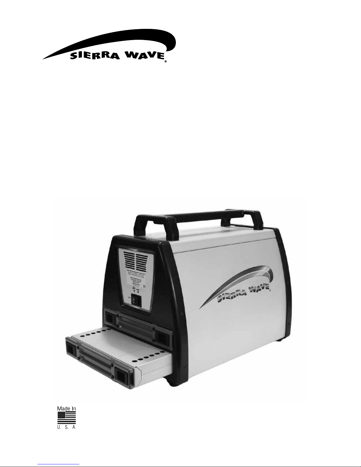
#9690 Incremental
1500-Watt Energy Center
#9691 500W Battery Pack
Shown with one #9691
500W Battery Pack
Patent
Pending
Page 2
2
IMPORTANT WARNINGS & SAFEGUARDS
Sierra Wave® 1500-Watt Incremental Energy Center comes equipped with a 500Wh capacity and
can be expanded to 1500Wh capacity incrementally, and increasable as energy needs increase. Start
with the #9690 unit, which includes a 500Wh internal battery and add up to two more 500Wh battery
packs (#9691 sold separately) as needed. The Energy Center features a pure sine wave AC inverter
and a lightweight LiFePO4 (lithium iron phosphate) battery. This power storage and distribution center
features a battery management system that handles all battery charging, power demand, and battery
switching automatically. Charge the Energy Center from any 120V AC electrical outlet or from an
auxiliary solar collector and operate a variety of appliances and tools from multiple 120V, 12V, or USB
power outputs. Energy peace of mind for the home, farm, cabin, or work site.
IMPORTANT WARNINGS & SAFEGUARDS
Read all instructions thoroughly before operating this unit to avoid injury to self or property and to
avoid damaging the unit. Keep instructions handy for reference during use.
ENERGIZED EQUIPMENT - ELECTRICAL SHOCK & EXPLOSION HAZARDS
GENERATES LETHAL VOLTAGES
• Do not submerge in liquid or operate in wet environments. Device is not waterproof
or water resistant. Operate in dry environments only. Failure to do so could cause
injury and damage the unit.
• Do not operate in flammable or explosive environments
• Do not operate if the unit is damaged in any way including loose electronics or if
charging cords are frayed and wires are exposed.
• Do not plug inverter 120V AC outlets into external 120V AC outlets of any kind
• Do not place foreign objects inside the power outlets
• Do not disassemble. There are no user serviceable parts. Contact the manufacturer
for all repairs.
• Do not use any AC powered devices over 1200W for risk of damage to the batteries
or inverter
• Monitor battery regularly during charging
• Do not use to operate any medical life support equipment
• Consult your physician before using with CPAP devices or other non-life support
medical equipment
• Do not block the air inlets or vents
• Do not replace fuses with larger amperage values. Use only specified fuses.
• Not recommended for use or storage below 14º (-10ºC) or above 120ºF (49ºC).
Place out of direct sunlight to prevent overheating.
• Administer close supervision when operating around children or persons with
disabilities
• Check dangerous goods shipping regulations before shipping
DANGER: Contains lithium high-energy batteries. Follow all precautions to prevent injury,
property damage and fire at all times during storage and operation.
• Never store or use in temperatures above 120°F (49°C)
• Keep away from sparks, open flames and heat sources
• Do not drop, puncture or incinerate
• Stop use immediately if you notice a leak or damage to the battery or unit. If it
malfunctions contact Customer Service at 800-227-0196.
• Follow your local battery disposal regulations
Page 3

3
WARNING: The #9690 Incremental 1500-Watt Energy Center and #9691 500-Watt Battery Pack
are only serviceable by Aervoe Industries, Inc. or an authorized repair facility. Do not dismantle.
Warranty is void if the device is opened by any unauthorized personnel. Call Aervoe Industries,
Inc. at 800-227-0196 for repair information.
Battery SDS is available online at www.aervoe.com.
FCC REQUIREMENTS
Warning: Changes or modifications to this unit not expressly approved by the party responsible for
compliance could void the user’s authority to operate the equipment.
The following covers the 10A AC charger only.
Note: This equipment has been tested and found to comply with the limits for a Class B digital device,
pursuant to Part 15 of the FCC Rules. These limits are designed to provide reasonable protection
against harmful interference in a residential installation. This equipment generates, uses, and can
radiate radio frequency energy and, if not installed and used in accordance with the instructions, may
cause harmful interference to radio communications. However, there is no guarantee that interference
will not occur in a particular installation. If this equipment does cause harmful interference to radio
or television reception, which can be determined by turning the equipment off and on, the user is
encouraged to try to correct the interference by one or more of the following measures:
• Reorient or relocate the receiving antenna
• Increase the separation between the equipment and receiver
• Connect the equipment into an outlet on a circuit different from that to which the receiver is
connected
• Consult the dealer or an experienced radio/TV technician for help
Operation is subject to the following two conditions: (1) this device may not cause harmful
interference, and (2) this device must accept any interference received, including interference that may
cause undesired operation.
Page 4
4
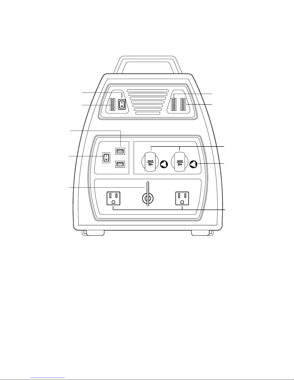
PARTS IDENTIFICATION
AC Power Switch
Aux Battery #2 Meter
Aux Battery #1 Meter
Main Power Key
DC Power Switch
USB Power Ports
Main Battery Meter
12V Fuses
12V DC Outputs
120V AC Outputs
Page 5
5
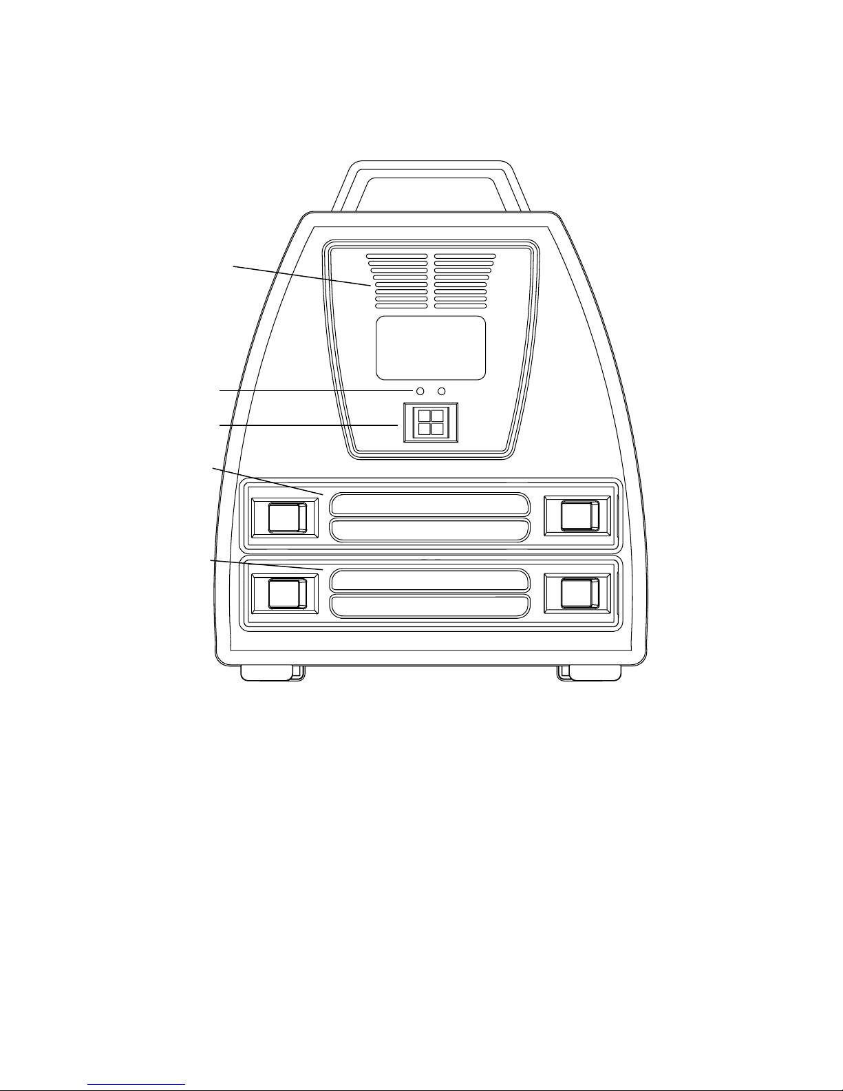
Inverter Exhaust Fan
Solar Charge
Indicators
DC IN
AUX Battery #2 Slot
AUX Battery #1 Slot
Page 6

6
CHARGING & STORAGE See instructions below for installing additional 500-Watt Battery Packs
For maximum efficiency and battery life, fully charge before first use and after each use. Charge every
3 months during storage. With routine discharge (use) and recharge cycles the batteries will maintain
proper conditioning. Failure to do so can affect battery performance and life cycle.
NOTE: Monitor regularly during charging.
Two methods of charging are available:
1. Use the included 120V/220V – 10A AC Charger
2. Use a compatible solar panel (Sierra Wave #9590 Solar Collector recommended)
IMPORTANT: All power outlets are automatically disabled while charging. Once charging is complete
and the power source has been removed, the outlets will become functional again. By keeping
additional Battery Packs charged and ready to go you can avoid disruption in service.
AC Charging: (included)
The optimum method of charging the #9690 Energy Center and any installed #9691 Battery Packs.
1. Turn the MAIN POWER KEY counter-clockwise to OFF.
2. Turn the AC POWER SWITCH OFF.
3. Plug the red/black Anderson DC end of the 120V AC Charger into the DC IN socket.
4. Find a suitable grounded 120V AC outlet rated for 15A or higher and plug in the power cord.
5. The LED indicator on the charger will be RED when charging is in progress and will turn GREEN
when a complete battery charge is reached. While charging, the BATTERY METERS will cycle
from low to high.
6. When unplugged from the power source, the MAIN BATTERY METER will indicate the strength
of the internal battery – All 10 LEDs means the unit is fully charged. AUX BATTERY #1 and #2
METERS will indicate the strength of additional installed batteries in the same manner.
7. The internal cooling fan will cycle on and off to maintain proper internal temperature during
operation.
8. Disconnect the charger once charging is complete.
Solar Charging: (solar panel not included)
The Energy Center can be charged using solar power. Aervoe recommends the Sierra Wave #9590
120-Watt Solar Collector. Contact Aervoe Industries if other solar collectors are being considered to
ensure compatibility.
1. Read the instructions provided with the solar collector for set-up instructions and cautions prior
to use.
2. Place the solar collector and the Energy Center outdoors, on a level surface, in a bright sunny
location. The Energy Center can be placed behind the solar collector, or indoors, to keep it out of
direct sunlight and temperatures over 140°F. A 30-ft. Extension Cable #9503 is sold separately to
allow it to be set up further away.
3. Connect a recommended solar panel to the DC IN socket on the Energy Center. The MC4 cable
on the solar panel will connect to the MC4 end of the included MC4 TO ANDERSON ADAPTER
CABLE. The Anderson plugs on the cable will connect to the DC IN socket.
4. When solar voltage is present, the CHARGING LED will glow RED and the BATTERY METERS will
cycle from low to high.
5. When charging is complete the CHARGE COMPLETE LED will glow GREEN.
6. When unplugged from the power source, the MAIN BATTERY METER will indicate the strength
of the internal battery – All 10 LEDs means the unit is fully charged. AUX BATTERY #1 and #2
METERS will indicate the strength of additional installed batteries in the same manner.
7. Disconnect the solar collector once charging is complete.
Page 7

7
Battery Meters
The Energy Center has three battery meters and each is associated with an individual battery (one for
the included 500Wh battery and one for each auxiliary batteries, if installed). They provide a visual
reference of the battery’s level when charging and discharging within +/- 10%. If battery level becomes
too low, the battery meter will display the last two red bars on the meter. Once the battery level drops
to 1 red bar it will shut down completely to prevent damage to the battery. It will need to be recharged
before using again.
ADDING ADDITIONAL #9691 BATTERY PACKS (sold separately)
To increase battery capacity, additional 500Wh battery packs are available and up to two may be
installed into the #9690 Incremental 1500-Watt Energy Center. This increases capacity from 500Wh
to 1000Wh or a maximum 1500Wh. An unlimited number of Battery Packs may be kept charged and
ready to replace Battery Packs that have discharged.
IMPORTANT: Remove Battery Packs from the Energy Center if they will be stored for more than 7 days.
Installing
1. Turn off the MAIN POWER KEY.
2. Remove the battery compartment cover in either AUX BATTERY #1 OR #2 SLOT by sliding the
latches toward the middle of the unit. Keep the battery compartment cover because it will be
replaced when the battery is removed.
3. Slide a #9691 Battery Pack into the opening with the Sierra Wave logo facing up and the power
connectors going in first. Full connection will be made when the latches click into place.
4. Turn on the MAIN POWER KEY and turn the AC or DC POWER SWITCH on. The Battery Meter
associated with the installed battery should turn on and show the status of the charge (1-10
bars). If it does not register try reinstalling for a better connection.
Charging
1. Additional installed Battery Packs #9691 will be charged when charging power is supplied to the
#9690 Energy Center as described prior.
2. Battery Packs may also be charged outside of the #9690 Energy Center using the 120V AC
Charger supplied with the #9690 Energy Center or sold separately as #9692 Battery Charger.
a. Place the Battery Pack on a level, non-metal surface and out of direct sunlight.
b. Plug the red/black Anderson DC end of the 120V AC Charger into the input on the back of
the Battery Pack.
c. Find a suitable grounded 120V AC outlet rated for 15A or higher and plug in the power
cord.
d. The LED indicator on the AC charger will be RED when charging is in progress and will turn
GREEN when a complete battery charge is reached.
e. Disconnect the charger once charging is complete.
3. WARNING: The solar charge controller that is included with the #9580 and #9590 Solar Collectors
or other non-specified lithium battery solar charge controller should not be used when charging
Battery Packs. Contact Aervoe Industries, Inc. for information on the proper charge controller to
use and installation instructions.
Page 8
8
OPERATING INSTRUCTIONS
Once charged, the Energy Center is ready to use. All power outputs may be used simultaneously as
long as the total power draw of all devices plugged in does not exceed the maximum power rating of
the installed batteries. For optimum battery life avoid draining the batteries below 1 bar on the Battery
Meter. If possible, recharge before capacity drops that low and the unit shuts down.
System On and Off
1. Turn the MAIN POWER KEY clockwise to ON.
2. Turn the AC or DC POWER SWITCH to ON depending on the devices you will be operating.
3. The MAIN BATTERY METER should illuminate and indicate the status of the internal 500W
battery. If auxiliary #9691 Battery Packs are installed, the AUX BATTERY #1 & #2 METERS will
also illuminate.
4. To shut the system off when not in use including long-term storage, turn all POWER SWITCHES
OFF, and turn OFF the MAIN POWER KEY and remove it from the Energy Center.
5. Disconnect all devices.
120V AC Power Operation (Pure Sine Wave Inverter)
Pure Sine Wave Inverter Information: Pure sine wave power is suitable for most AC devices and
power supplies used in electronic equipment, transformers, and motors. Aervoe assumes no liability if
used with medical equipment. DO NOT use with any life support system. The 120V AC Outlets cannot
be used while charging. Any attempt to do so will cause the system to safely shut down.
CAUTION: The 120V AC operation can safely power common AC appliances and devices with a
maximum power output of 120V AC/10A or 1200 watt continuous power (based on #9690 Energy
center with 2-#9691 Battery Packs = 1500Wh capacity). It is the user’s responsibility to verify that the
device you wish to operate does not exceed the power specifications listed below to prevent inverter
overload and damage to the Energy Center or your device.
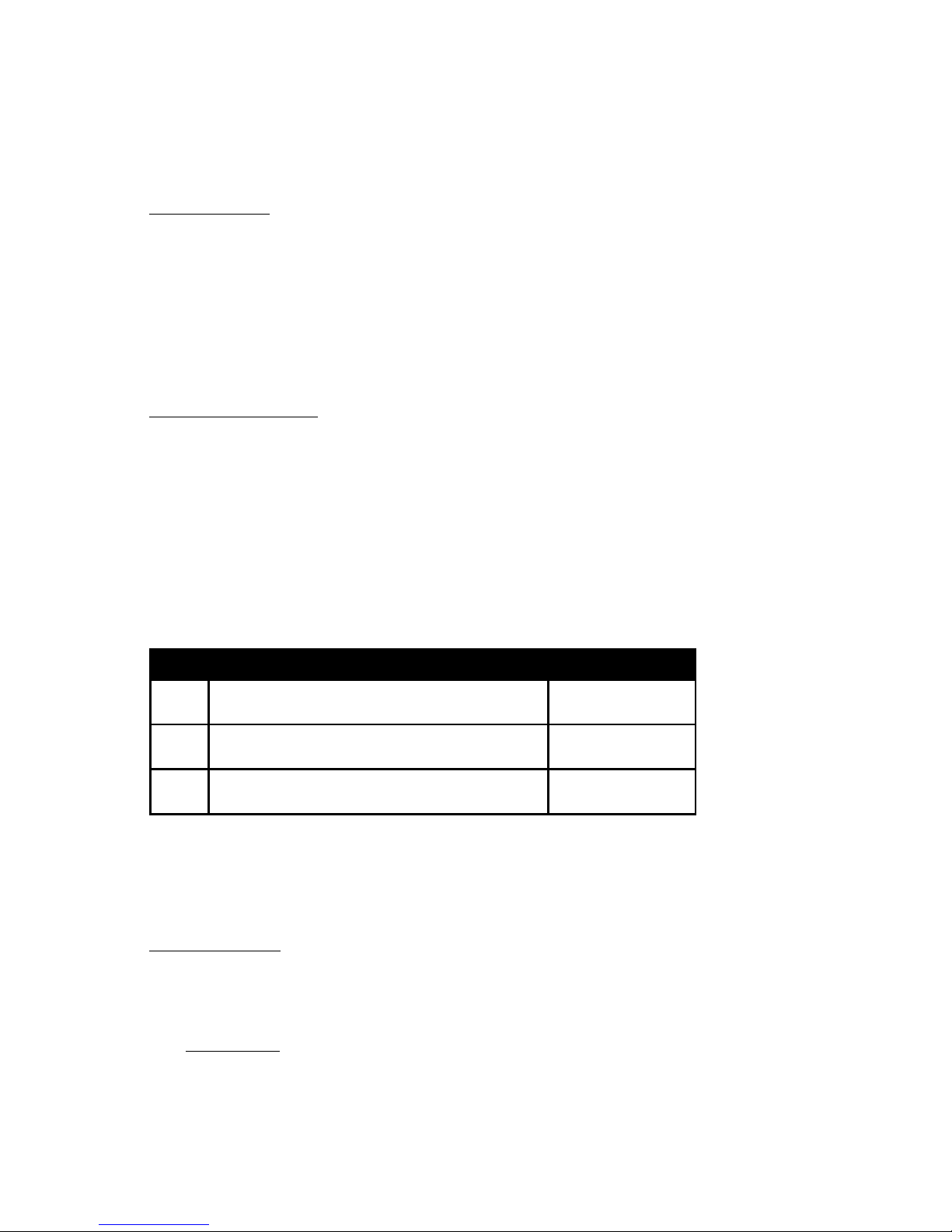
POWER SPECIFICATIONS
➊
#9690 Energy Center
(500Wh capacity)
400W (3.5-4A) max
➋
#9690 Energy Center + 1 #9691 Battery Pack
(1000Wh capacity)
800W (6.5-7A) max
➌
#9690 Energy Center + 2 #9691 Battery Packs
(1500Wh capacity)
1200W (10A) max
1. Turn the MAIN POWER KEY and AC POWER SWITCH on.
2. Plug in your 120V AC device to either of the 120V AC OUTPUTS and operate as normal.
3. Disconnect the device when not in use.
4. If overload occurs, the inverter will automatically shut-down. Disconnect all devices and retry.
DC Power Operation
The DC power operation includes a DC POWER SWITCH that when switched on provides power to
the USB ports and the 12V DC sockets. NOTE: These outputs cannot be used during charging. Any
attempt to do so will cause the system to safely shut down.
12V DC Output
The 12V DC operation can operate 12V devices rated at 15A (180W) per outlet. Do not operate
devices higher than 15A. Overload and short-circuit protection fuses are located next to each
12V DC receptacle. If these need to be replaced, make sure the DC POWER SWITCH and MAIN
POWER KEY are off. Replace with the specified fuse.
1. Turn the MAIN POWER KEY and DC POWER SWITCH on.
2. Plug in your 12V DC device (15A OR LESS) to either of the 12V DC OUTPUTS and operate as normal.
3. Disconnect the device and turn off the DC POWER SWITCH when not in use.
Page 9

9
USB 5V/2A DC Output
The USB operation can operate devices using a standard USB connection and up to 5V/2.5A per
port.
1. Turn the MAIN POWER KEY and DC POWER SWITCH on.
2. Plug in your USB device to either of the USB POWER PORTS and operate as normal.
3. Disconnect the device and turn off the DC POWER SWITCH when not in use.
TROUBLESHOOTING
CAUTION: This unit and its accessories are not user serviceable. If you experience any trouble with
your Energy Center contact Aervoe Industries, Inc. and speak with a Product Specialist at 800-227-
0196. To avoid damage to the unit and avoid injury do not dismantle.
Common Remedies
• Make sure the MAIN POWER KEY is on
• Ensure all power cords are connected securely
• Check each BATTERY METER to ensure there is adequate power storage. If not, recharge
as described above.
• Check the charging indicator on the AC Charger to make sure they are illuminating correctly
• If using a solar collector, make sure it is connected properly, in adequate sunlight, and the
CHARGING indicator is illuminated on the Energy Center
120V AC Output Failure
• Make sure the AC POWER SWITCH is on and the AC POWER LED illuminated
• Make sure your device meets the power specifications listed on page 8
• Check the 120V AC Outlet for damage or obstruction
• Verify the 120V device being used is working and not damaged
12V DC Output Failure
• Make sure the MAIN POWER KEY and DC POWER SWITCH is on
• Check the 12V DC fuse associated with the suspect 12V DC output. If it has blown replace
with the same specified fuse. Follow fuse replacement instructions above.
• Check the 12V DC Outlet for damage or obstruction
• Verify the 12V device being used is working and not damaged
USB Output Failure
• Make sure the MAIN POWER KEY and DC POWER SWITCH is on
• Check the USB Outlet for damage or obstruction
• Verify the device being used is working and not damaged
Fault Mode
When the system senses a fault condition (explained below) it will automatically shut down all power
outputs and reset the system after 15-seconds. If the fault is not cleared, the system will go back into
the fault mode until the cause of the fault is cleared or the system is powered off.
System Faults and Remedies
Current Draw is Over the Maximum Allowable Limit
• The system automatically senses the number of added 500-watt batteries installed and
adjusts the maximum allowable current draw set point.
• If the set-point is exceeded, reduce the current draw to clear the fault.
Battery Level Too Low
• If the battery level falls below 10.0V because the batteries are discharged or the system
wattage load has been exceeded for the number of installed batteries, the system will enter
fault mode. Recharge the batteries to clear the fault.
Internal Temperature Too High
• The system has multiple temperature sensors. If the internal temperature reaches a
dangerous level or a cooling fan fails, the system will go into fault mode. Turn off the
system and allow it to cool before restarting.
Page 10
10
CARE AND MAINTENANCE
• Charge and use routinely as described above
• Dust regularly with a clean dry cloth to prevent dust and dirt from building up on the vents
and power inputs/outputs. Do not use water, detergents, or other chemicals to clean the unit
• Store in a clean, dry place when not in use
• Turn off all power switches and remove the MAIN POWER KEY when not in use or before
long term storage
TECHNICAL INFORMATION
SPECIFICATIONS
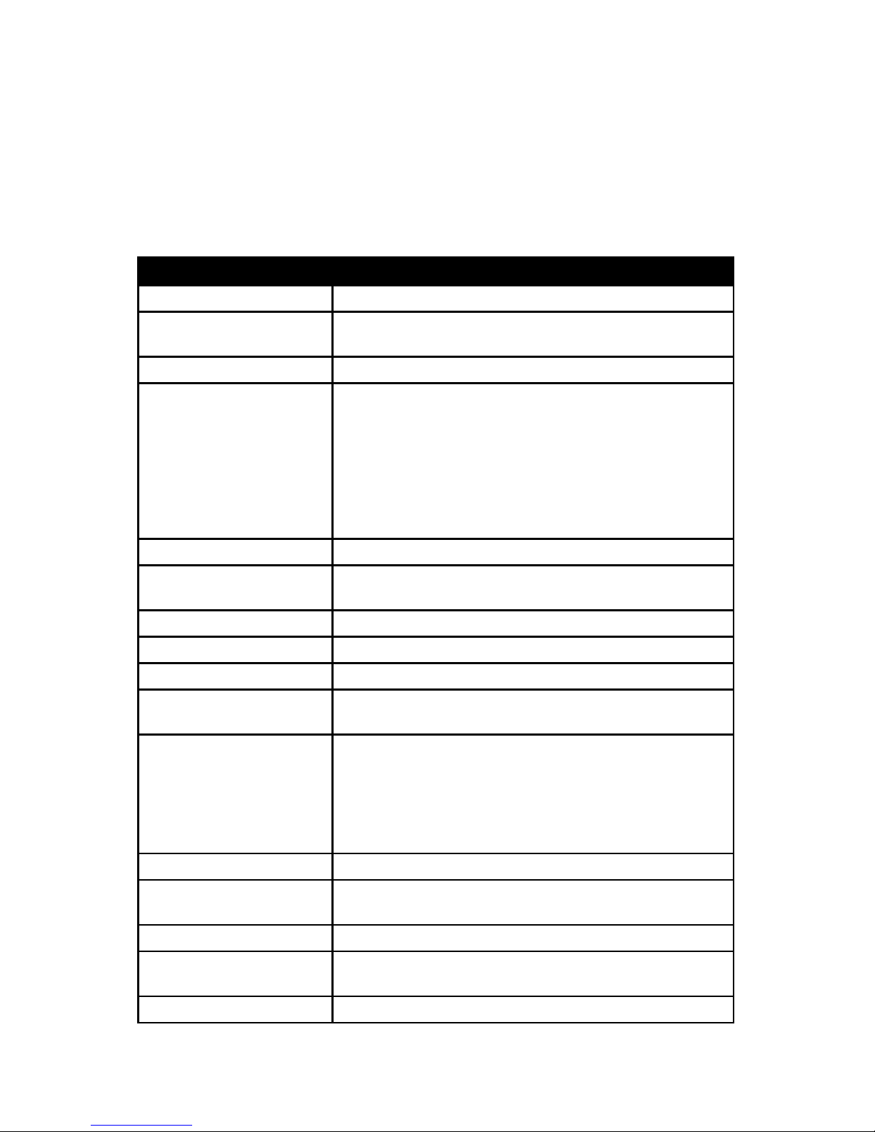
BATTERY TYPE LiFePO4 (lithium iron phosphate) 12.8V/40Ah (500Wh)
AUXILIARY BATTERY #9691 Up to 2 may be added. 40Ah – 12.8V (500Wh per battery). Sold
separately.
BATTERY LIFESPAN 1500+ cycles per battery (cycle = charge and discharge)
INVERTER Wave form: pure sine wave
Voltage: 120V AC/60Hz
Amps: 12.5 max (total)
Maximum power output: 1500W
Continuous power output: 1200W (80% efficiency)
Peak surge rating: 3000W
DC input (battery): 12-15V DC, 10.5-15V DC
Resettable fuse (not replaceable)
PROTECTION CIRCUIT Built-in overcharge, short circuit and low battery protection
BATTERY PROTECTION FUSE
(not user replaceable)
Main Battery: 58V/60A
Auxiliary Batteries: 58V/60A per battery
REPLACEABLE FUSE 2 - 15A 3AG fuses (for each 12V DC outlet)
DC INPUT POWER 14.8V/10A, 150W max
SOLAR INPUT POWER 17.5V-35V DC, 150W max
120V AC WALL CHARGER Input: 120V AC, 100-230V, 50/60Hz, 100VA
Output: 14.8V/10A, UL & FCC approved adapter
RATED OUTPUT POWER 2 outlets - 12V DC, 15A (180W) max per outlet
2 outlets - USB 3.0 (5V/2.5A), 10.5W per outlet
2 outlets - 120V AC, 60Hz, 10A total for both outlets
• 500Wh battery = 400 max. load
• 1000Wh battery = 800 max. load
• 1500Wh battery = 1200 max. load
OPERATING TEMPERATURE 14º- 120ºF (-10º - 49ºC)
CHARGING & STORAGE
TEMPERATURE
32º - 120ºF (0º - 49ºC)
BASE UNIT WEIGHT 32 lbs. (14.5Kg)
#9691 AUXILIARY BATTERY
WEIGHT
16.25 lbs. (7.4Kg)
DIMENSIONS 12” x 19.25” x 15” (30.5 x 48.9 x 38cm)
Page 11
11
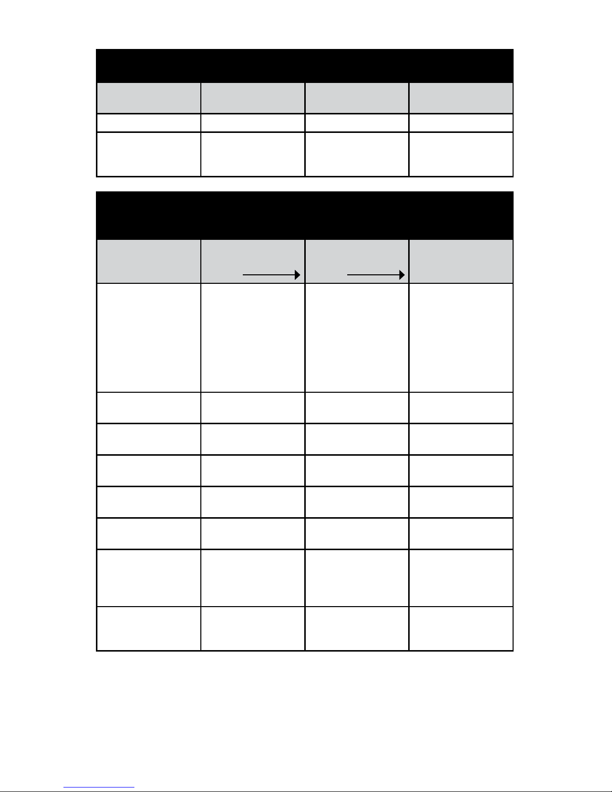
CHARGE TIME
Times vary depending on battery state and available sunshine during
solar charging
#9690 Unit with
500Wh built-in battery
#9690 + 1 #9691
500Wh Battery Pack
#9690 + 2 #9691
500Wh Battery Packs
120V AC/10A Charger 5 hours 10 hours 15 hours
120-Watt Solar
Collector #9590 (7A
max)
7-8 hours 14-15 hours 21-22 hours
SAMPLE
OPERATING TIMES
Example only based on full battery charge. Actual run times vary
depending on the device being operated.
To verify the device wattage multiply its volts x amps = watts.
#9690 Unit with
500Wh built-in battery
500W
#9690 + 1 #9691
500Wh Battery Pack
1000W
#9690 + 2 #9691
500Wh Battery Packs
1500W
18-cu.ft. Refrigerator
(400-600W)
Operating times based
on an already cooled
internal temperature
and not starting from
room temperature
(example only)
Up to 6 hours Up to 12 hours Up to 18 hours
1000W AC Microwave Exceeds AC power
limit
Exceeds AC power
limit
Up to 90 minutes
17” LCD TV (100W,
120V AC)
5 hours 10 hours 15 hours
Laptop with 60W
battery
Up to 8 full recharges Up to 16 full recharges Up to 24 full recharges
250W AC Sump Pump
(1/2 HP)
2 hours 4 hours 6 hours
250-500W AC small
power tools
Up to 2 hours Up to 4 hours Up to 6 hours
Aervoe #8712 20-Watt
LED Work Light (runs
for 4 hours on a full
charge)
Up to 5 recharges Up to 10 recharges Up to 15 recharges
Max Burton #6905
Digital Stove To Go®
(130W max)
Up to 3.5 hours (at
lowest temperature)
Up to 7 hours (at
lowest temperature)
Up to 10.5 hours (at
lowest temperature)
1-year warranty to the original registered owner on all products from date of purchase. User returns,
exchanges and defective refunds must be made with the original place of purchase, for the first 30 days
after purchase in accordance with the distributor/retailer’s return policy. After 30 days of purchase and
with a Warranty Registration card on file, the buyer can make a product warranty claim directly with
Aervoe Industries, Inc. There is no warranty for buyer’s remorse. Because Aervoe cannot control Buyer’s
handling or use of product, Aervoe makes no warranty expressed or implied when not used or stored
in accordance with directions. Aervoe shall not be liable for cost of labor, incidental or consequential
damages, and this warranty is limited to replacement or repair of product or credit of purchase.
Page 12

12
AERVOE INDUSTRIES, INC.
Gardnerville, NV 89410 • 1-800-227-0196
www.aervoe.com • [email protected]
9690inst; cs05/16
 Loading...