

Page 1

SIERRA VIDEO SYSTEMS, INC.
Skirt Generator User’s Guide
587135-00 AND 587144-00 Digilinx Modules
V 1.1
Page 2
Introduction
The Skirt Generator consists of two modules, an aspect ratio rescaler module and a video insertion module.
The rescaler accepts a 4:3 aspect ratio 270Mbps SMPTE 259M video signal and produces a 16:9 aspect
ratio corrected 270Mbps SMPTE 259M video signal suitable for use in a wide screen format. The
insertion module combines this main video signal with a second 270Mbps SMPTE 259M video signal
which typically contains graphics to be displayed in the skirt video area. The main aspect ratio
compensated material can be positioned anywhere within the widescreen format image via rear panel
controls. Additional features include placing adjustable width borders between the main video and the
surrounding skirt video, a user controllable border matte generator, and adjustable width garbage masking
for the main video edges.
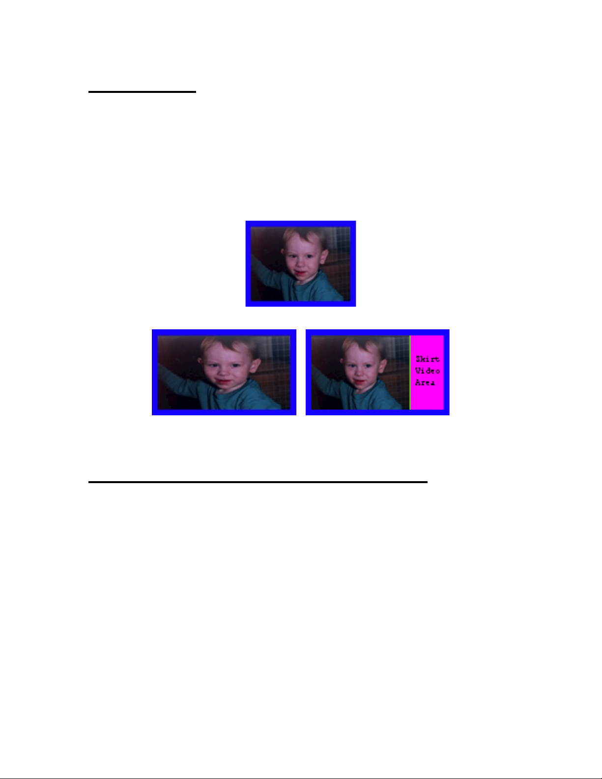
4:3 Aspect Ratio Source Material
16:9 Wide Screen Format
Uncompensated Aspect Ratio Compensated
Skirt Generator Peripheral Connections
The skirt generator rear panels provides the following signal connections to the user:
DIG. VID. IN (rescaler)
input to the rescaler module.
DIG. VID. OUT (rescaler)
outputs from the rescaler module. They are copies of one another and either may be used
without affecting the other. One should be connected to the mixer/inserter A input as shown in
the following interconnection diagram.
DIG. VID. IN A (mixer/inserter)
270Mbps SMPTE 259M video input to the module from the rescaler.
DIG. VID. IN B (mixer/inserter)
signal input containing the video to be displayed in the skirt area.
ANLG. REF. IN (mixer/inserter)
DIG. VID. OUT (mixer/inserter)
video outputs from the skirt generator to a 16:9 aspect ratio monitor. They are copies of one
another and either may be used without affecting the other.
- This BNC connector serves as the 270Mbps SMPTE 259M main video
- These two BNC connectors provide 270Mbps SMPTE 259M video
- This BNC connector serves as the main aspect corrected
- This BNC connector serves as the 270Mbps SMPTE 259M
- These BNC connectors should not be used at this time.
- These two BNC connectors provide 270Mbps SMPTE 259M
Skirt Generator User’s Guide
2
Page 3

Skirt Generator Interconnection Diagram
Rescaler Module Rear Panel Controls
The two switches on the rear of the rescaler module control the horizontal position of the main 4:3 aspect
ratio video within the wide screen 16:9 aspect ratio image, the edge mask width, the border width, the color
of the border matte and the storage/recall of the above parametes in non-volatile EEPROM memory within
the rescaler module. This section describes the utilization of these switches.
SWA
- Switch A is used to select the parameter to be adjusted by switch B. These are the parameters and
their corresponding switch positions:
Table 1:
SWA Positions and Their Functions
Sw. Function
Pos.
Selected
0 Set the least significant nibble of the main video position within the 16:9 format image.
1 Set the most significant nibble of the main video position within the 16:9 format image.
2 Set the width of the mask used to crop garbage off the edges of the main video.
3 Set the width of the border between the main video and the skirt video area.
4 Set the least significant nibble of the border matte Cr color difference.
5 Set the most significant nibble of the border matte Cr color difference.
6 Set the least significant nibble of the border matte Cb color difference.
7 Set the most significant nibble of the border matte Cb color difference.
8 Set the least significant nibble of the border matte luminance.
9 Set the most significant nibble of the border matte luminance.
A-D Unused.
E Select the EEPROM register in which to save the above parameters.
F Recall a skirt generator setup from the EEPROM register.
Skirt Generator User’s Guide
3
Page 4

SWB
- Switch B expresses the numeric value of the parameter pointed to by Switch A. If Switch A enters
and leaves any mode without Switch B being changed, the parameter value stored in RAM for that mode
will not be influenced by the switch value. If Switch B is changed, the parameter pointed at by Switch A
will take on the value of Switch B until Switch A is changed to another setting. Here is an example of how
to set the border matte color :
1) Set switch A to position 9. The border matte selector displays should appear overlaid on the Skirt
Generator output video. The current border matte color lies at the intersection of the horizontal and vertical
cross hairs on the upper color vectorscope display. The luminance of the current matte color is indicated on
the lower monochrome bar display.
2) Rotate switch B and note the corresponding coarse changes in the border luminance. As the luminance
changes, the color gamut available on the vectorscope display also changes. Leave switch B set as close as
possible to the desired luminance.
3) Set switch A to position 8.
4) Rotate switch B and note the increased resolution of the luminance changes around its previous value.
Rotate the switch to fine tune the luminance to the desired value.
1) Set switch A to position 7. The luminance bar should disappear, leaving only the color vectorscope
display overlaid on the Skirt Generator output video. The current matte color lies at the intersection of the
horizontal and vertical cross hairs.
2) Change switch B and note the coarse motion of the vertical Cb crosshair on the vectorscope display and
the corresponding coarse changes in the border matte color. Move the vertical crosshair as close as possible
to the desired color.
3) Set switch A to position 6.
4) Change switch B and note the increased resolution of the crosshair motion around its previous position.
Rotate the switch to fine tune the crosshair to the desired Cb color difference.
5) Set switch A to position 5 and rotate switch B to coarse adjust the horizontal Cr crosshair.
7) Set switch A to position 4 and fine tune the matte Cr color difference using switch B.
8) Rotate switch A until the matte selector displays disappear from the Skirt Generator output video.
When using the switches to change the Skirt Generator settings, Switch B’s value expresses the
hexadecimal value of the parameter being adjusted. Any color whose numerical Y, Cb, and Cr values are
known can be directly entered into the border matte generator by setting switch B to the appropriate
hexadecimal values for each nibble. Table 2 lists such values for 75% and 100% saturated color bar colors.
Skirt Generator User’s Guide
4
Page 5

Table 2: Color Bar Y, Cb, Cr Values and Their Corresponding Switch Settings
Switch B Settings in Hexadecimal
Color
Y Cb Cr swA= 9 8 7 6 5 4
White 940 0 0 E B 0 0 0 0
Black 64 0 0 1 0 0 0 0 0
Yellow (100%) 840 -448 73 D 2 9 0 1 2
Cyan " 678 151 -448 A 9 2 5 9 0
Green " 578 -297 -375 9 0 B 6 A 3
Magenta " 426 297 375 6 A 4 A 5 D
Red " 260 -151 448 4 1 D B 7 0
Blue " 164 448 -73 2 9 7 0 E E
Yellow (75%) 646 -336 55 A 1 A C 0 D
Cyan " 525 113 -336 8 3 1 C A C
Green " 450 -223 -281 7 0 C 9 B A
Magenta " 335 223 281 5 3 3 7 4 6
Red " 260 -113 336 4 1 E 4 5 4
Blue " 139 336 -55 2 2 5 4 F 3
Parameter Storage
The current parameter settings can be stored to one of seven EEPROM registers for the present video
standard by setting SWA to position E and setting SWB to any value from 1 to 7. The storage to EEPROM
occurs when SWA is then moved OUT of position E. If SWB is set to any value except 1-7, moving SWA
out of position E will NOT result in parameter storage to EEPROM. Note that separate storage locations
exist for 625 and 525 line parameters (7 for each). 7 locations are also reserved for 270Mbps streams
which cannot be identified as 525 or 625 line signals (for compatibility with future 270Mbit streams).
Parameter Recall
Stored parameter settings can be recalled from one of seven EEPROM registers for the present video
standard by setting SWA to position F and setting SWB to any value from 1 to 7. As SWB is changed, the
the settings are recalled from the corresponding EEPROM register. On power up the module automatically
configures the module to the settings in effect when power was lost.
Specifications
Video Input Standard SMPTE 259M
Video Input Connector BNC female
Video Input Return Loss >15dB @ 270MHz(75 Ohm referenced)
Video Input Range Source must be within 200 meters of input when using Belden 8281
or equiv.
Video Output Standard ` SMPTE 259M
Video Output Connector BNC female
Video Output Jitter <350 picoseconds peak-to-peak with 10 Hz high pass filter
Power Consumption 5V, <1.5A
8V, <0.5A
-8V, <0.15A
Operating Temperature Range 0 to 50 C, non-condensing
Operating Humidity Range 0 to 95% RH
Skirt Generator User’s Guide
5
 Loading...