

Page 1

SIERRA VIDEO SYSTEMS, INC.
Digital Mixer User’s Guide
507144-00
V 1.7
Digital Mixer User’s Guide 1
Page 2
Introduction
The DigiLinx Digital Mixer performs dissolve functions between two 270 Mbps component serial digital
video signals. The output can also perform a 'fade to black' operation using either externally provided
video source and internally generated 'black' signal. Dissolve rates are user programmable via an
RS232/RS422 control port and transitions can be triggered via the same control port or one of nine
General Purpose Input(GPI) pins which are activated by way of simple connections to ground.
Both inputs to the mixer are automatically retimed to an adjustable phase sync generator synchronized to
an external analog video reference. The auto-timers have a +/- 1/2 line correction range relative to the
adjustable phase reference. Delay through the mixer is roughly 0.5H (assuming inputs are centered in
their auto-timing range).
Analog reference to internal reference timing is adjustable via local controls or SmartLinx control points;
including Windows PC's, the 1RU frame control panel, and the Alpha One controller. SmartLinx
controllers also have the ability to set dissolve ratios and to trigger transitions. The mixer is a 'two slot'
DigiLinx module; providing a rear panel 25 pin D connector for direct access to GPI's and local serial
control.data) .
Peripheral Connections
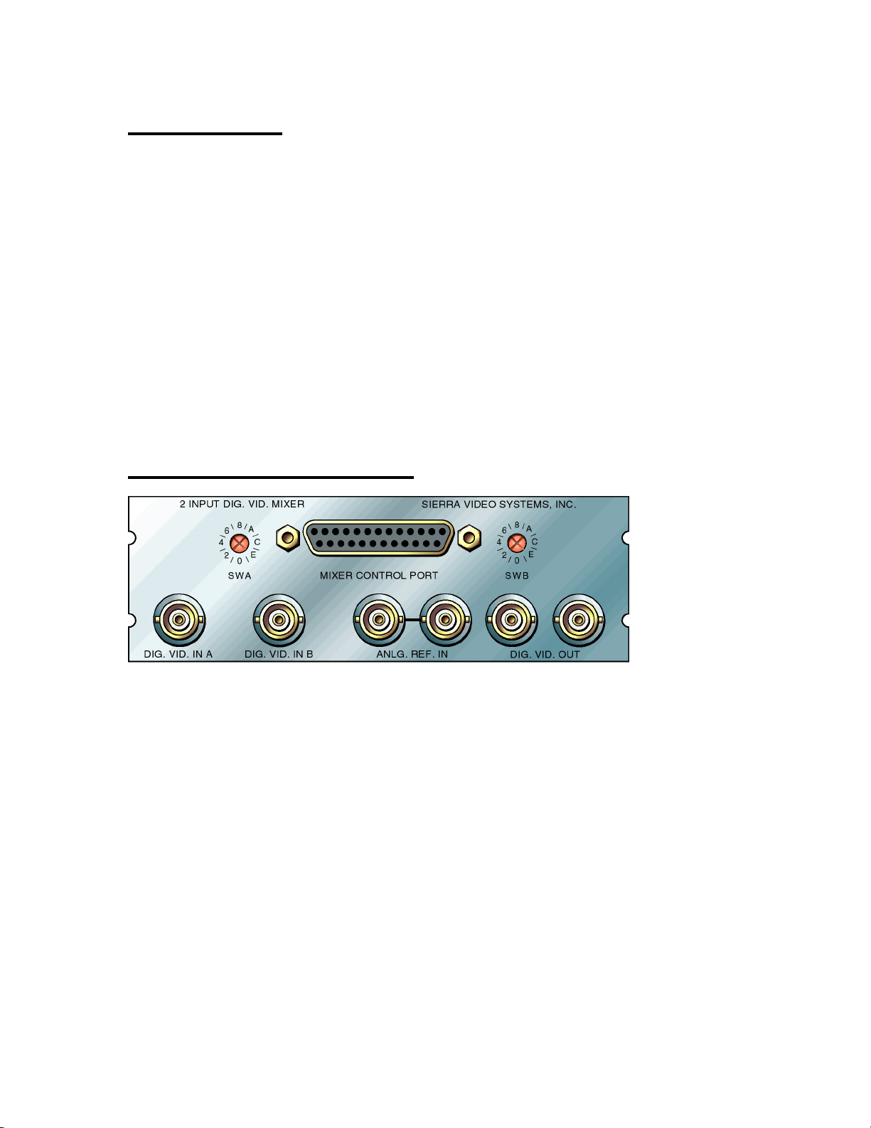
The rear panel provides the following signal connections to the user:
DIG. VID. IN A - This BNC connector serves as a 270Mbps SMPTE 259M signal input to the
product. Signals applied here are fed to the mixer and, optionally, to the clock generation
circuitry for the module.
DIG. VID. IN B - This BNC connector serves as a 270Mbps SMPTE 259M signal input to the
product. Signals applied here are fed to the mixer.
DIG. VID. OUT - These two BNC connectors provide 270Mbps SMPTE 259M signal outputs from
the product. They are copies of one another and either may be used without affecting the other.
ANLG. REF. IN - These two BNC connectors are wired to one another and provide
synchronization inputs to the product. 0.3 to 2V p-p composite sync or video with or without
color burst must be provided as a reference for video output timing. If the reference signal is
not being ‘looped through’ to another load, the unused input should be terminated with 75
Ohms.
MIXER CONTROL PORT - This 25 pin female ‘D’ connector provides access to an
RS232/RS422 serial data control port and to 9 General Purpose Input control pins which are
grounded by the user to trigger transitions. The following table describes the pin assignments
for this connector:
Digital Mixer User’s Guide 2
Page 3

Table 1: Mixer Control Port Pin Assignments
Pin
Number Description
1 RS422 TX+ (outgoing data)
2 RS232 TX/RS422 TX-(outgoing data)
3 RS232 RX/RS422 RX-(incoming data)
4 RS422 RX+ (incoming data)
5 Ground
6 GPI1 (Cut to “A” limit, then dissolve to “B” VIDEO limit)
7 GPI2 (Cut to “B” limit, then dissolve to “A” VIDEO limit)
8 GPI3 (Cut to closest limit (“A” or “B”), then fade to BLACK on opposite limit)
9 NC
10 NC
11 NC
12 NC
13 NC
14 GPI4 (Cut to closest limit (“A” or “B”), then dissolve to opposite VIDEO limit)
15 GPI5 (Cut to “B” VIDEO limit)
16 GPI6 (Cut to “A” VIDEO limit)
17 GPI7 (Cut to BLACK on the farthest limit (“A” or “B”))
18 GPI8 (Cut to VIDEO on the farthest limit (“A” or “B”))
19 GPI9 (Cut to closest limit (“A” or “B”), fade to BLACK, then to opposite limit)
20 Ground
21 NC
22 NC
23 NC
24 NC
25 NC
Rear Panel Control
The reference to output skew values and other settings stored in the module can be entered and recalled
via the two switches on the rear of the mixer module. This section describes the utilization of these
switches.
SWA - Switch A is used to select the parameter to be adjusted by switch B. These are the parameters
and their corresponding switch positions:
Table 2: SWA Positions and Their Functions
Sw. Function
Pos. Selected
0 Set least significant nibble of reference-to-output delay.
1 Set 2nd least sig. nibble of reference-to-output delay.
2 Set 3rd least sig. nibble of reference-to-output delay.
3 Set 4th least sig. nibble of reference-to-output delay.
4 Set 5th least sig. nibble of reference-to-output delay.
5 Set most sig. nibble of reference-to-output delay.
6 Set 525(0) or 625(1) line default video std. for skew programming.
7 Set analog(ANLG. REF. IN)(0) or digital(DIG. VID. IN A)(1) sync reference.
8-D Unused.
E Set EEPROM reg. in which to save parameters.
Digital Mixer User’s Guide 3
Page 4

F Recall parameters from EEPROM register.
SWB - Switch B expresses the numeric value of the parameter pointed to by Switch A. If Switch A
enters and leaves any mode without Switch B being changed, the parameter value stored in RAM for that
mode will not be influenced by the switch B value. If Switch B is changed, the parameter pointed at by
Switch A will take on the value of Switch B until Switch A is changed to another setting. Here is an
example of how to set the three most significant nibbles of the time delay to zero when Switch B is
initially set to ‘0’:
1) set switch A to position 5,
2) change switch B to any value other than zero,
3) set switch B to zero,
4) set switch A to position 4,
5) change switch B to any value other than zero,
6) set switch B to zero,
7) set switch A to position 3,
8) change switch B to any value other than zero,
9) set switch B to zero.
In other words, to tell the module you want to change a value you must change switch B.
During time delay nibble entries, Switch B’s value expresses a hexadecimal number. This means switch
position A indicates a value of 10, position B, a value of 11, position C, a value of 12, position D, a value
of 13, position E, a value of 14, and position F indicates a value of 15.
Internal Controls
A number of configuration switches and jumpers can be accessed by removing the module from its
chassis. The following describes these controls.
S1 - This is actually a collection of 8 switches contained in a single package. Labels on the package
identify the 8 individual switches within the package. The ‘1’ and ‘0’ references in the
descriptions below correspond with those on the module silk screen next to the switch.
Individual switches function as follows.
S1-1,S1-2 - These switches control the transition time from one input to the other or from
either input to or from ‘black’. The transition times resulting from each switch setting are:
Table 3: GPI Transition Period Selection
Transition Switch
Period Settings
½ secondS1-1=1,S1-2=1
Digital Mixer User’s Guide 4
Page 5

1 second S1-1=1,S1-2=0
2 seconds S1-1=0,S1-2=1
10 seconds S1-1=0,S1-2=0
These timings assume that S1-3 has been set to correspond with the video system in use.
S1-3 - Set this to 0 in 50Hz video system applications; 1 in 60 Hz video system applications.
S1-4 - Not used
S1-5,6,7,8 - These switches set the rear panel mixer control serial port module address. The
address can be determined from the following table.
Table 4: Mixer Control Port Address Selection
Mixer Port S1Address 5678
0 1111
1 1110
2 1101
3 1100
4 1011
5 1010
6 1001
7 1000
8 0111
9 0110
10 0101
11 0100
12 0011
13 0010
14 0001
15 0000
JP3,JP4 - These jumpers control the electrical interface for the SmartLinx network port on the
module. When the jumpers connect pin 1 to pin 2(JP3 and JP4 must be set to the same
position), the SmartLinx network connection is compatible with RS232. This mode allows
direct wiring to a personal computer(via SmartLinx connectors on the rear of DigiLinx frames)
but can only be connected to one module at a time. When the jumpers connect pin 2 to pin 3,
the SmartLinx network connection is compatible with RS485. This mode allows many
SmartLinx modules to share the same two wire control bus, but requires the presence of a
SmartLinx controller device on the network, such as a Host Adapter Module or a 1RU frame
control panel.
JP6,JP8 - These jumpers control the electrical interface for the rear panel user port on the module.
When the jumpers connect pin 1 to pin 2(JP3 and JP4 must be set to the same position), the
connection is compatible with RS232. This mode allows direct wiring to a personal
computer(via SmartLinx connectors on the rear of DigiLinx frames) but can only reliably used
over a 10 to 50 foot range(depending on the wire type and environmental noise). When the
jumpers connect pin 2 to pin 3, the connection is compatible with RS422. This mode allows
connection to a user supplied controller hundreds of feet away, but requires the presence of a
RS422 compatible serial port in the user’s controller.
Digital Mixer User’s Guide 5
Page 6

JP7 - This jumper is used to connect an optional termination resistor to the rear panel user port
RS422 receiver. When pin 1 is connected to pin 2, a 100 Ohm resistor is connected between
the RX+ and RX- inputs of the RS422 receiver. When pin 2 is connected to pin 3, no
termination is connected between these two signals. When using RS422 mode, long cable runs
with only one module(this one) at the opposite end of the cable from the transmitter should be
terminated by connecting this resistor across the received signal pair. In multi-drop situations,
only one receiver(at the end of the cable farthest from the transmitter) should have its
terminator connected. Terminators in other modules should be disconnected.
S2,S3 - These are ‘on board’ replacements for SWA and SWB(respectively; see rear panel control)
and are not normally installed. If you have a board with rear panel switches AND S2 and S3,
make sure S2 and S3 are always set to ‘0’ to ensure that they do not interfere with rear panel
switch functionality.
Using the GPI interface
The GPI interface consists of 9 ‘ground closure’ inputs which ,when connected to ground, trigger
predefined video transitions. In practice, the application of a signal less than 1 Volt above ground for 50
msec. or more will activate that input. The GPI inputs are ‘pulled up’ to 5 Volts via a 10KOhm resistor if
not loaded externally. The interface can be enabled and disabled (locked out) via software. The initial
state of the GPI interface is ON. Subsequently, “G” commands can be issued via the mixer control port
serial interface to enable and disable the GPI interface.
The GPI inputs are available on a 25 pin D connector and are enumerated in ‘Peripheral Connections’
(above). When they are activated (and the GPI interface is enabled), the previously defined(see Table 1)
video transitions occur.
The mixer will automatically perform cuts to black on the opposite side, if necessary, to accomplish
transitions..
Using the Mixer Control Port Serial Interface
A dedicated RS232/RS422 serial control interface is provided to allow more extensive control of the
mixer via user supplied automation. For those wishing to write their own control software, the following
protocol information is provided.
The serial interface requires and produces a 9600 baud asynchronous data stream using 8 data bits, no
parity, and 1 stop bit. ASCII characters are used to exchange information. The DIP switches are used to
select a 4-bit address to which the device responds when the address is received in a serial command
string(see Table 5).
A command string must start with ** and end with !!. Within the command string, spaces and control
characters are ignored. The command string may contain 0 or more commands, and each command can
be destined for any one of up to 16 units attached. A command consists of a letter which designates which
of the available commands is to be executed, followed by one or two digits giving the decimal address of
the mixer unit that is to respond to the command, followed by comma-separated decimal numbers which
provide further arguments to the command. Here’s an example command string: ** G14,2 T8,0,5 !!
Each mixer has a limit on the number of commands it can handle in a single command string. Each unit
ignores the commands for other units, so only those addressed to it count toward the limit. Each mixer can
handle about 65 bytes worth of command data, where the command character (e.g. “G” or “T”) counts as
Digital Mixer User’s Guide 6
Page 7

one byte, the address characters and commas count as 0 bytes, and each numeric argument counts as one
byte, except for duration (in frames), which count as two bytes. Thus, the command string
“**X12,0,1,25,75,987!!” counts as 7 bytes.
The protocol is designed to minimize the necessity of data transmission. There is no response to a
command string unless a command within it requests some information. In that case, the response is of a
similar form as the command string itself: it starts with **, then a command designator, a mixer address,
and additional arguments, followed by!! and a carriage return character for good luck.
The following commands are defined. Each command has one or two digit characters, denoted as ‘aa’,
following the command letter. These comprise a decimal number from 0 to 15 specifying the mixer unit
(determined by the ‘address’ DIP switches) which is to respond to the command.
Command Form Description
Gaa,x Enable or disable GPI interface or request GPI enable status.
x=0 -> Lock out GPI interface
x=1 -> Enable GPI interface
x=2 -> respond with **Gaa,y!!
where y =0(locked) or 1 (enabled) is current GPI status.
Qaa Sends software version number response:
Qaa,Vx.x (C) 1993 Sierra Video Systems, Grass Valley, CA!!
where x.x is software version number, e.g. V1.1
Saa Respond with **Saa,x,y,rr!!
giving current mixer status (as it will be at completion of ongoing mix, if one is active).
x=0 -> “A” has black selected x=1>-”A” has video selected
y=0 -> “B” has black selected y=1->”B” has video selected
rr=Mix ratio 0 to 99 0 -> 100%”A” 99 -> 100%”B”
Taa,rr,ddddd Start a mix transition from current mix ratio to a mix ratio of rr =0 to 99,
completing the transition in ddddd frames, where ddddd =o to 32767. If a mix
transition is already in progress, it is immediately completed (to its target ratio) and then this
new transition is begun.
Cut to specified mixer inputs and set the mix ratio. Cancel any activity mix transition.
x=0->Cut to black on “A” x=1->Cut to video on “A”
y=0->Cut to black on “B” y=1->Cut to video on “B”
rr=Mix ratio 0 to 99 0->100% “A” 99->100% “B”
Waa Wait for current mix transition to complete before executing additional commands.
Xaa,x,y,rr,ss,ddddd Combine U and T commands. First send Uaa,x,rr and then follow with Taa,ss,ddddd,
thus starting a transition from a ratio of rr =0 to 99, to a ratio of ss =0 to 99, with a transition duration of
ddddd =0 to 32767 frames. Mixer inputs are cut to x(“A” side) and y (“B” side). If a mix transition is already
in progress, it is immediately aborted and then the new transition is begun.
The following are sample command strings:
Command Result
**Q0!! Mixer with address 0 responds with:
**Q0, V1.1 (C) 1993-1993 Sierra Video Systems, ...!!
**U13,1,1,25!! Mixer with address 13 cuts “A” and “B” to video inputs and
sets mix ratio to 25% “A”, 75% “B”. If a mix transition is in
progress, it is canceled and the new settings take effect
immediately.
Digital Mixer User’s Guide 7
Page 8

**T13,90,60 S13!! Mixer #13 starts a mix transition from its current value of
25% to a value of 90%, which will take 60 frames to
complete. It requests status, which is returned as:
**S13,1,1,90!!
even though the mix transition has not yet completed.
**X9,1,0,85,10,120 W9 S9 !! Mixer #9 cuts its “A” input to video, its “B” input to black, and
starts a mix transition to 10% “A” which will take 120 frames
to complete. The W command causes a wait until the transition completes, then the S command executes and sends
the status:
**S9,1,0,10 !!
**U12,1,1,0 T12,99,200 W12 T12,20,
105 GO,1 !!
Mixer #12 cuts its “A” and “B” inputs to video and its mix ratio
to 0%, then starts a mix transition to 99% (which is actually
100%; you may not specify 100) with a duration of 200
frames. The W command causes Mixer #12 to wait until this
transmission is finished, then the following T command is
executed, which starts another transition to a mix ratio of
20% in 105 frames. Meanwhile, Mixer #0 has enabled its GPI
interface (it doesn’t wait for the Mixer #12 transition to
complete because the W command is addressed to #12).
**GO,2 !! **S15 !! Mixer #0 responds with:
**GO,1 !!
indicating its GPI interface is enabled, and Mixer #15 responds
with:
**S15,0,1,80 !!
indicating its “A” input is black and its “B” input is video and
its mix ratio is 80%. Note that commands may be combined
inside of **!! or separate **!! commands may be sent.
However, there is a very small limit (20 characters for the
total length of command strings following one that is
being executed), so the former method is preferred.
Auto-Timing Digital Video Inputs
Each digital video inputs is automatically aligned to the nearest horizontal sync signal generated within
the Digital Mixer. This means digital sources don’t have to be aligned with ‘pixel precision’ as they enter
the module. However, the sources MUST be within a horizontal line period of each other. The sources
must also arrive with timing which is ‘advanced’(earlier in time) from the video output of the module by
1.5usec to 1.5usec + 1 horizontal line period(less 37nsec).
It is important to remember that auto-timers are not frame synchronizers or time base correctors. The
circuits will tolerate the specified range of input timing errors, but these must be static errors. If
externally selected sources don’t fall within the specified timing windows, or if they aren’t frequency
locked to the Digital Mixers reference input, pixel errors will result.
Determining Reference to Output Delay Settings
The reference-to-output delay settings are entered and stored as hexadecimal numbers which indicate the
number of 27MHz clock cycles of delay between any point on the reference input and a corresponding
Digital Mixer User’s Guide 8
Page 9

point on the video output signal. The module has an intrinsic reference-to-output delay limit of one frame
time, which is 900,900 clocks in 525 line formats and 1,080,000 clocks in 625 line formats, so entering
delays greater than these values will(depending on the reference applied to the module), be limited to the
appropriate number of clocks in a full frame. Note that each delay is available with only one setting
which means that, since zero delay is available, the highest valid values are equal to the number of clocks
in a frame period MINUS ONE (900,899 for 525; 1,079,999 for 625). Otherwise, the switch values for
the desired time delay can be calculated from an absolute time goal by
1) Multiplying the desired delay time by 27,000,000,
2) rounding to the nearest whole number, and
3) expressing the result as a hexadecimal number.
This last step is most easily realized with a calculator featuring a hexadecimal number notation mode.
The resulting number is then entered into the module starting with the most significant nibble (SWA set
to position 5), even if the value of this nibble is zero. Note that this most significant nibble only has two
values; 0 or 1. Any other value will be truncated to 1. If two adjacent nibbles require the same value to
be entered , it is necessary to move SWB to another position and back again; otherwise, the module will
think you don’t want to change that register to something other than it’s original value.
When using the module to ‘fine tune’ signal re-entry timings, it is often easier to monitor the time skewed
output relative to some ’correctly’ timed signal and adjust the time delay nibbles until a satisfactory timing
is achieved. Reference-to-output delay settings beyond the maximum values allowed are automatically
limited to the maximum value available.
The following table gives a few popular values for delay settings expressed in the hexadecimal notation
used by the rear panel switches. Note that ‘second’ value time delays are actually the nearest number of
whole frames(at the line rate referred to) to the given number of seconds; allowing the video output to be
‘in time’ with the video input. The most significant digit in the ‘Switch Settings in Hexadecimal’ column
would be entered while SWA is set to position 5, the second most significant digit entered with SWA set
to position 4, etc.
Table 5: A Collection of Popular Delays and Their Corresponding Switch Settings
Reference to Output Number of Switch Settings
Delay Clock Cycles in Hexadecimal
(1) ‘525’ line 1,716 0006B4
(2) ‘525’ lines 3,432 000D68
(3) ‘525’ lines 5,148 00141C
(4) ‘525’ lines 6,864 001AD0
(5) ‘525’ lines 8,580 002184
(6) ‘525’ lines 10,296 002838
(7) ‘525’ lines 12,012 002EEC
(8) ‘525’ lines 13,728 0035A0
(9) ‘525’ lines 15,444 003C54
(10) ‘525’ lines 17,160 004308
(1) ‘625’ line 1,728 0006C0
(2) ‘625’ lines 3,456 000D80
(3) ‘625’ lines 5,184 001440
(4) ‘625’ lines 6,912 001B00
(5) ‘625’ lines 8,640 0021C0
(6) ‘625’ lines 10,368 002880
(7) ‘625’ lines 12,096 002F40
(8) ‘625’ lines 13,824 003600
(9) ‘625’ lines 15,552 003CC0
Digital Mixer User’s Guide 9
Page 10

(10) ‘625’ lines 17,280 004380
Parameter Storage
The present reference-output sync delay and reference source selection can be stored to one of twelve
EEPROM registers for the present video standard by setting SWA to position E and setting SWB to any
value from 1 to C. The storage to EEPROM occurs when SWA is then moved OUT of position E. If SWB
is set to any value except 1-C, moving SWA out of position E will NOT result in parameter storage to
EEPROM. Note that separate storage locations exist for 625 and 525 line parameters(12 for each).
Parameter Recall
The present reference-output sync delay value and reference source selection can be recalled from one of
twelve EEPROM registers for the present video standard by setting SWA to position F and setting SWB to
any value from 1 to C. As SWB is changed, the modules delay will reflect the parameters previously
stored in the corresponding EEPROM register. Setting SWB to 0, D or E will result in a delay value of
0(no reference to output timing skew) and analog reference synchronization being loaded. Moving SWA
out of position F will store the register nuumber indicated by SWB into EEPROM, causing this parameter
set to be loaded whenever power is cycled or board reset occurs. Note that separate storage locations exist
for 625 and 525 line parameters(12 for each).
Specifications
Video Input Standard SMPTE 259M
Video Input Connector BNC female
Video Input Return Loss >15dB @ 270MHz(75 Ohm referenced)
Video Input Range Source must be within 200 meters of input when using Belden 8281
or equiv.
Video Output Standard ` SMPTE 259M
Video Output Connector BNC female
Video Output Jitter <350 picoseconds peak-to-peak with 10 Hz high pass filter
Ref.-Output Delay Adj. Res. 37nsec.(one 27MHz clock cycle)
Ref.-Output Delay Adj. Range One video frame period
Video. Delay 1.5 microseconds to 1 horizontal line period plus 1.5 microseconds
Power Consumption 5V, <1.5A
8V, <0.8A
-8V, <0.15A
Operating Temperature Range 0 to 50 C, non-condensing
Operating Humidity Range 0 to 95% RH, non-condensing
All specifications subject to change without notice.
Digital Mixer User’s Guide 10
 Loading...