

Page 1

Sierra Video Systems
SmartLinx Bus Adapter
July 17, 2000 at 3:04 PM
Page 2

Sierra Video Systems SmartLinx Bus Adapter busadap.doc
Table of Contents
1. INTRODUCTION .......................................................................................................................................4
2. DIP AND ROTARY SWITCH SETTINGS...............................................................................................4
2.1 DIP S
2.2 R
2.3 R
2.4 R
3. LEDS.............................................................................................................................................................6
3.1 S
3.2 N
4. HOST EIA-232 PORTS...............................................................................................................................7
5. SMARTLINX EIA-485 PORT AND TERMINATION JUMPERS........................................................7
6. EEPROM PARAMETERS.........................................................................................................................8
7. SMARTLINX MESSAGE SET.......................................................................................................... ........9
7.1 B
7.2 P
OTARY SWITCHES
OTARY SWITCH
OTARY SWITCH
TARTUP DIAGNOSTICS AND
ORMAL OPERATION
US ADAPTER BASIC MESSAGES
OLLER MESSAGES
S6 ...................................................................................................................................... 4
WITCH
S2
S3 ...............................................................................................................................5
S4 ...............................................................................................................................5
...............................................................................................................................11
S1...............................................................................................................5
AND
, LEDS,
LEDS D
URING STARTUP
AND WATCHDOG TIMER
............................................................................................................9
............................................................................6
..........................................................................7
2
Page 3

Sierra Video Systems SmartLinx Bus Adapter busadap.doc
Figures
F
IGURE
F
IGURE
F
IGURE
F
IGURE
F
IGURE
F
IGURE
T
ABLE
T
ABLE
T
ABLE
T
ABLE
T
ABLE
1: DIP S
2: R
3: R
4: R
5: LEDS.............................................................................................................................................................6
6: T
WITCHES
OTARY SWITCHES
OTARY SWITCH
OTARY SWITCH
ERMINATION RESISTOR JUMPERS
...............................................................................................................................................4
S2-S1 ............................................................................................................................. 5
S3.......................................................................................................................................5
S4.......................................................................................................................................6
.................................................................................................................8
Tables
1: H
OST PORT 9-PIN FEMALE
2: S
MARTLINX PORT 3-PIN MALE SWITCHCRAFT CONNECTOR PINOUT
3: P
ARAMETERS FOR UNIVERSAL “T
4: U
NIVERSAL MESSAGES UNDERSTOOD OR SENT BY BUS ADAPTER MODULES
5: U
NIVERSAL MESSAGES UNDERSTOOD OR SENT BY POLLER-ENABLED BUS ADAPTERS AT THE POLLER
A
DDRESS
..............................................................................................................................................................12
D C
ONNECTOR PINOUT
” M
ESSAGE
.........................................................................................7
..............................................................7
.................................................................................................9
..............................................10
3
Page 4
Sierra Video Systems SmartLinx Bus Adapter busadap.doc
1. Introduction
This document describes the control program software for the Sierra Video Systems SmartLinx Bus Adapter,
a.k.a. SmartLinx Host Adapter.
Additional documents should be referred to for complete information:
• Circuit schematics for the control processor board.
• Bus Adapter Processor Board C Runtime Support Code document.
• SmartLinx protocol document.
• 68302 Processor C Function Library document.
• 68000 Processor Library document.
• General-Pur pose C Function Library document.
• Motorola 68302 processor handbook.
• Sierra Systems C Compiler Manual
2. DIP and Rotary Switch Settings
This section describes DIP and Rotary switch settings.
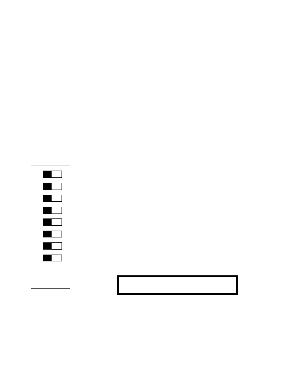
2.1 DIP Switch S6
1
2
3
4
5
6
7
Sw 1: Fast Acquire Mode: 0 = 15 seconds to poll all non-responding devices
1 = 5 seconds to poll all non-responding devices
Sw 2: Disconnect Tolerance: 0 = Disconnect after one failure to respond to a poll
1 = Disconnect after
Sw 3: Flow Control: 0 = Hardware flow control (CTS/RTS)
Sw 4: Poller Enable: 0 = Bus adapter not enabled for polling
1 = Bus adapter is enabled for polling
Sw 65: Host Port B Speed: 00 = 9600 bps; 01 = 38,400 bps; 10 = 115,200 bps; 11 = 230,400 bps
Sw 87: Host Port A Speed: 00 = 9600 bps; 01 = 38,400 bps; 10 = 115,200 bps; 11 = 230,400 bps
8
Off On
(0) (1)
Figure 1: DIP Switches
four consecutive
(affects both ports) 1 = Software flow control
Any DIP switch change results in an immediate automatic
reset.
poll response failures
4
Page 5

Sierra Video Systems SmartLinx Bus Adapter busadap.doc
2.2 Rotary Switches S2 and S1
Rotary switches S2 and S1 set the SmartLinx bus address of the bus adapter. This must be set to a value
between D2 and F6, and in fact the upper limit should generally be no more than F5, see rotary switch S4 below.
5
4
3
7 8 9
6
2
1
0
F
A
B
C
D
E
5
4
3
7 8 9
6
2
1
0
F
A
E
B
C
D
Any rotary switch change results in
an immediate automatic reset.
S2
(left digit)
Figure 2: Rotary Switches S2-S1
S1
2.3 Rotary Switch S3
Rotary switch S3 is not currently used.
5
4
3
7 8 9
6
2
1
0
F
A
B
C
D
E
S3
Figure 3: Rotary Switch S3
2.4 Rotary Switch S4
(right digit)
Any rotary switch change results in
an immediate automatic reset.
Rotary switch S4 sets the number of addresse s just beyond the SmartLinx bus address set by S2-S1 to be
reserved for use by applications running on hosts connected to this bus adapter. This must be set so that when this
value is added to the S2-S1 address, the result is a value between D2 and F6 and does not overlap the address
range assigned to any other host adapter in the system. Normally S4 is set to at least 1.
For example, one host adapter might be set to address F0 with S2-S1, and assigned addresses F1-F4 for host
applications by setting S4 to 4. Then, a second host adapter might be set to address F5 with S2-S1, and assigned
address F6 for host applications by setting S4 to 1.
Each host application must obtain a SmartLinx address from the bus adapter. Since addresses are limited, this
switch allows the user to limit the number of them that this bus adapter reserves for itself and applications connected
to it, in case additional bus adapters are being used. A setting of 2, for example, would be sufficient for two more
addresses just above the S2-S1 address, allowing two host applications to run at one time (one on each host port, or
two on a single host port).
5
Page 6

Sierra Video Systems SmartLinx Bus Adapter busadap.doc
5
4
3
7 8 9
6
2
1
0
F
A
D
E
B
C
Any rotary switch change results in
an immediate automatic reset.
S4
Figure 4: Rotary Switch S4
3. LEDs
The host adapter has a set of 10 LEDS in one corner of the board, plus an additional LED inside the reset
switch. The following sections describe their use.
- 8V OK
+8V OK
+5V OK
7
6
5
4
3
2
1
RESET
Figure 5: LEDs
3.1 Sta rtup Diagnostics and LEDs During Startup
When the bus adapter is powered on, the first thing it does is perform a series of diagnostic tests of its flash
memory and RAM memory. The progress of these tests is indicated by the LEDs, as follows:
1. LEDs 1-7 and the RESET LED are flashed on and off rapidly for one second. This indicates that the
bus adapter is alive and the software is starting up.
2. LED #1 is turned on, then the longword checksum of the two FLASH memory devices (U7 and U8) is
computed. The result should be 0. If not, LED #1 is flashed for about three seconds, then normal
operation is attempted.
3. LEDs #2 and #3 are turned on, then a random test pattern is written to the two static RAMs (U9 and
U11) and then read back to verify. If the pattern verifies incorrectly, the LED of the RAM that verified
incorrectly is flashed for about three seconds. LED #2 is flashed if the even byte (U11) is bad, and LED
#3 is flashed if the odd byte (U9) is bad. Both will be flashed if both bytes are bad at the first incorrect
word verification. After flashing, normal operation is attempted.
4. The value of the first two rotary switches, S1 and S2, is displayed on LEDs 1-7 and the RESET LED for
one second. Then, the value of the second two rotary switches, S3 and S4, is displayed on the LEDS for
one second. Then, the value of the 8 DIP switches is displayed on the LEDs for one second. Then, LED
#4 is turned on for one second to indicate that all tests passed, and normal operation begins.
6
Page 7

Sierra Video Systems SmartLinx Bus Adapter busadap.doc
3.2 Normal Operation, LEDs, and Watchdog Timer
When normal operation begins, the first thing the software does is to initialize itself. Before starting
initialization, the value 0x09 is loaded into LEDs 1-7. This indicates that initialization is starting. Then, after each
step in the initialization process, the LED value is incremented. Finally, when initialization is finished and the main
program loop of the bus adapter begins, the LED value is continually incremented from 0 to 127 and then back to 0
again. This indicates that the bus adapter is alive and operating. At the same time that the LEDs are incremented,
the 68302 watchdog timer is reset. These two things happen in a low-priority loop, which runs only when the bus
adapter is not busy processing SmartLinx messages.
4. Host EIA-232 Ports
The bus adapter has two 9-pin female D connectors for EIA-232 ports that are used for connecting one or two
host computers to it. Five wires are used, including transmit and receive data, and CTS/RTS hardware flow control.
The pinout is as follows:
1. Pin 1: Not connected.
2. Pin 2: Output, circuit BA (Transmit Data)
3. Pin 3: Input, circuit BB (Receive Data)
4. Pin 4: Not connected.
5. Pin 5: Signal GND, circuit AB
6. Pin 6: Not connected.
7. Pin 7: Input, circuit CB (Clear to Send)
8. Pin 8: O ut put, circuit CA (Request to Send)
9. Pin 9: Not connected.
Table 1: Host Port 9-pin Female D Connector Pinout
This pinout is designed so that the host computer can use the IBM COM port standard, a 9-pin male D
connector. A straight-through cable can be used. Only pins 2, 3, 5, 7, and 8 must be connecte d. All other pins may
be connected or left unconnected.
The cable length is limited by what EIA-232 can tolerate at the data rate that is used. Refer to the DIP switches
for port speed settings. The host ports operate with 8 data bits, 1 stop bit, and no parity.
RTS and CTS are used for flow control between the bus adapter and the host. The host computer must be
enabled for RTS/CTS flow control when it is talking to the bus adapter.
5. SmartLinx EIA-485 Port and Termination Jumpers
The bus adapter has one Switchcraft TA3M 3-pin male connector for the EIA-485 port that is used for
connecting it to the SmartLinx frames. The pinout is as follows:
1. Pin 1: V-
2. Pin 2: Signal GND.
3. Pin 3: V+
4. Outside shield: Signal GND.
Table 2: SmartLinx Port 3-pin Male Sw it chcraft Connector Pinout
7
Page 8

Sierra Video Systems SmartLinx Bus Adapter busadap.doc
At the SmartLinx data rate of 125,000 bps with 8 data bits, 1 stop bit, and no parity, the cable length is limited to
about 1000 feet. Termination resistors are required at both ends of the cable. One end is the bus adapter, where
termination resistors are built onto the board, and enabled by installing two jumpers:
Figure 6: Termination Resistor Jumpers
For the other end of the cable, a special termination resistor cable is required. However, it has been observed
that for shorter cable lengths, the other end should remain unterminated.
The bus adapter can be plugged into a single-module SmartLinx frame, and then connected to the other
SmartLinx frames via the SwitchCraft 3-pin connector. This is the recommended setup, because the single-module
frame can be placed near the host computer(s) to keep the EIA-232 cable lengths short. An alternative is available,
however. The bus adapter can be inserted into any SmartLinx frame of any size, and it will connect to the SmartLinx
bus using the 25-pin connector that plugs into the frame. In that case, the SwitchCraft connector is not used.
6. EEPROM Parameters
The bus adapter board contains a 128-byte EEPROM non-volatile memory. It is currently used by the software
to store the following data:
1. The 8-character user device name given to the bus adapter.
2. The two-digit SVS “dash number” supplied during factory setup of the board.
3. The 6-digit SVS serial number supplied during factory setup of the board.
4. A hardware version number string supplied during factory setup of the board.
Only the first item can be changed by the user.
1
JP1
2
3
4
8
Page 9

Sierra Video Systems SmartLinx Bus Adapter busadap.doc
7. SmartLinx Message Set
The Bus Adapter has a basic set of SmartLinx messages that it supports at the bus adapter address set via rotary
switches S1-S2. If the Poller Enable DIP switch is turned on to enable polling, the bus adapter adds some additional
messages. However, these additional messages are supported via a different SmartLinx address: the poller address
of F7 hex. The following message descriptions are divided into two sections, one for the basic message set of the
bus adapter, and another for the poller-only messages.
7.1 Bus Adapter Basic Messages
Table 4 lists the universal SmartLinx messages that a Bus Adapter module understands and processes at the
address set using rotary switches S1-S2. For a full description of these messages, refer to the document SmartLinx
Protocol Description. The <CMD> byte of all universal messages is equal to the CmdChar character code (in
ASCII) plus hex 80. Universal messages other than those shown here are ignored, so if the universal message set is
ever extended, older modules can be assumed to ignore newer messages. The universal message “t” will contain the
following parameter values:
Parameter Value(s)
CatNum 507125
DashNum 0X
HardVersion Up to 19-character PLD dash number plus null terminator, typically only 2
characters. For example, “04” means the PLD dash number is -04.
SoftVersion 5 characters plus null terminator, “V1.05” for example.
Settings1 0 if bus adapter is NOT polling-enabled, 1 if it is the poller.
Settings2 Frame/slot address value. A value of 00 can indicate either frame C3-3 or that the
bus adapter is plugged into a single-module frame that has not been modified to
support SLOT and FRAME ID.
Settings3 DIP switch setting, 00-FF.
Settings4 Rotary switches S1/S2 setting, low nibble is S1, high nibble is S2.
Settings5 Rotary switches S3/S4 setting, low nibble is S3, high nibble is S4.
Settings6..8 Not used.
Table 3: Parameters for Universal “t” Message
The Bus Adapter does not use any module-private messages. All of its messages are universal message, and.
these are fully described in the SmartLinx protocol document.
CmdChar Direction Description
A
a
B
b
C
F
(Host)
(Address)
Bus Adapter
(Address)
(BusAdap Addr)
(BusAdap Addr)
(Connect)
(FrameID)
(Host)
Bus Adapter
Poller
Poller
Bus Adapter Host requests allocation of a SmartLinx address for use by an application, or
→→→→
Host Bus adapter informs host of address allocation or deallocation results.
→→→→
(Bus Adapter) Host informs bus adapter that it is starting or shutting down. Message source and
→→→→
(Host) Bus adapter responds with its address and host port ID of the host’ s port. Message
→→→→
Bus Adapter A connection to the Bus Adapter has been established by the poller. The Bus
→→→→
Bus Adapter I f the Bus Adapter board is in the specified slot and does not yet know its frame ID, it
→→→→
deallocates such an address. Message source address can be 0, it is ignored. The
Bus Adapter sends an “a” message in response.
destination addresses can be 0, they are ignored. The Bus Adapter sends a “b”
message in response.
destination address is 0, host does not yet have an address. The bus adapter sends
this message to its host ports, with a “Shutdow n” parameter that is TRUE, whenever
it starts up, to announce that it no longer has any host connections established.
Adapter sends a “t” message in response.
reads its frame ID and computes its
of the “t” message.
SmartLinx
address, which is placed in Settings2
9
Page 10

Sierra Video Systems SmartLinx Bus Adapter busadap.doc
H
(High Speed)
h
(High Speed)
L
(Loopback)
l
(Loopback)
N
(Name)
n
(Name)
P
(Poll Params)
R
(Reset)
r
(Reset)
r
(Reset)
T
(Type)
t
(Type)
U
(Unlock)
W
(Which)
w
(Which)
Any
Poller
Any
Poller Requests a temporary change in the EIA-485 bus data rate. The Bus Adapter sends
→→→→
All Announces a temporary change in the EIA-485 bus data rate. The Bus Adapter
→→→→
Bus Adapter Loopback send diagnostic message. The Bus Adapter sends data back to the sender
→→→→
Bus Adapter
Any
Bus Adapter Changes the Bus Adapter’s module name, or queries for the current module name.
→→→→
Bus Adapter
Bus Adapter
Any
Bus Adapter The Bus Adapter resets itself as if just powered up after receiving this message.
→
→
→ →
Bus Adapter
Poller
Any
Bus Adapter When the Bus Adapter receives an “r” message from the poller, it sends “P”
→→→→
Bus Adapter Changes the dash number, serial number, and hardware version number of the Bus
→→→→
Bus Adapter
Any
Any
Bus Adapter Unlocks certain Bus Adapter commands, such as the ability to modify the dash
→→→→
Bus Adapter Request for the Bus Adapter to send a “w” message reporting the message <CMD>
→→→→
Bus Adapter
this message when a host application requests that a message be sent in hi ghspeed mode.
receives messages on the bus at the higher speed for the specified time.
using an “l” message.
Any Loopback reply diagnostic message, sent in response to receiving an “L“ message.
→→→→
The Bus Adapter sends an “n” message in response.
Any The Bus Adapter reports its name in response to receiving an “N” message.
→→→→
Poller At startup, the Bus Adapter sends this message to set its polling parameters so that
→→→→
it will be repolled imm edi atel y, up to 20 times, wh enever i t sends a message.
Whenever a host application allocates a S martLinx address, this message is sent to
enable periodic polling
and idle polling
of the host application. When the
application deallocates its address, this message is sent agai n to disconnect the
device, reduce the polling frequency of the address, and terminate idle polling. After
receiving an “r” message from the poller, thi s message is sent several times to the
poller to reestablish the polling parameters that were probably lost when it reset.
All The Bus Adapter sends this message at startup to announce that it has just started
→→→→
up.
messages to the poller to reestablish polling parameters of itself and its
applications. See the “P” message above for mo re i n form ation.
Adapter (catalog number and software version number cannot be changed), or
queries for the catalog number, dash number, serial number, hardware version
number, software version number, reset flag, and settings1/ 2. The Bus Adapter
sends a “t” message in response. Unlocking (“U” command) is required before any
parameters can be changed. These parameters must only be changed by the factory.
Any The Bus Adapter reports its catalog number, dash number, serial number, hardware
→→→→
version number, software version number, reset flag, and setti ngs 1/ 2. It sends this
message as a general broadcast to all devices whenever it establi shes (or
reestablishes) a connection with the poller, e.g. at power-up and any time the
connection between the poller and Bus Adapter is dropped for some reason. This
message is also sent to the sender of a “T” message. The Bus Adapter hardware
version number is two ASCII characters (2-digit PLD dash number), and the software
version number is five ASCII characters (V#.##). Settings1 is TRUE iff the Bus
Adapter is polling enabled. Settings2 is the SmartLinx bus address corresponding
the frame and slot ID values of the Bus Adapter (the Bus Adapter’s SmartLinx
address is determined by the setting of rotary switches S1-S2). Settings3 is the DIP
switch setting. Settings4 is the rotary switch S1-S2 setting. Settings5 i s the rotary
switch S3-S4 setting.
number, serial number, and hardware version number.
bytes it understands and/or sends.
Any The Bus Adapter reports the message <CMD> bytes it understands and/or sends, in
→→→→
response to receiving a “W” message.
Table 4: Universal Messages Understood or Sent by Bus Adapter Modules
10
Page 11

Sierra Video Systems SmartLinx Bus Adapter busadap.doc
7.2 Poller Messages
When the Bus Adapter is poller-enabled with the appropriate DIP switch, it acts as the SmartLinx poller device.
The poller device responds to messages sent to the special poller address of 0xF7. The messages supported at this
address are separate from the ones described above for the basic Bus Adapter. It is as if the Bus Adapter were two
devices in one, except the poller does not respond to the important “T” message or send the “t” message.
The poller’s user module name cannot be changed with the “N” message. It is fixed as “Poller”.
Table 5 lists the universal SmartLinx messages that a Bus Adapter module understands and processes at the
poller address (0xF7) when it is poller-enabled. For a full description of these messages, refer to the document
SmartLinx Protocol Description. The <CMD> byte of all universal messages is equal to the CmdChar character code
(in ASCII) plus hex 80. Universal messages other than those shown here are ignored, so if the universal message set
is ever extended, older modules can be assumed to ignore newer messages.
11
Page 12

Sierra Video Systems SmartLinx Bus Adapter busadap.doc
CmdChar Direction Description
C
D
F
H
h
L
l
N
n
P
p
Q
q
R
r
W
w
X
x
Poller
(Connect)
(Disconnect)
(FrameID)
(High Speed)
(High Speed)
(Loopback)
(Loopback)
(Name)
(Name)
(Poll Params)
(Poll Params)
(Query)
(Query)
(Reset)
(Reset)
(Which)
(Which)
(eXclusion)
(eXclusion)
Poller
Poller
Any
Poller
Any
Poller
Any
Poller
Any
Poller
Any
Poller
Any
Poller
Any
Poller
Any
Poller
All A connection to some SmartLinx device has been established by the poller.
→→→→
All The poller has lost the connection to some SmartLinx device. Any mutexes that
→→→→
have been allocated by the device are automatically released.
All Every 200 ms the poller sends this message to all devices to allow those in a
→→→→
particular frame slot to use the frame ID lines to determin e which frame they are in.
Poller A SmartLinx device requests a temporary change in the EIA-485 bus data rate. The
→→→→
poller sends an “h“ message in response.
Any/All Sent in response to receiving an “H“ message. If the “H“ message request is
→→→→
denied, this message is sent only to the sender of the “H“ message. Otherwise, it is
sent to all devices to announces the beginning of a temporary change in the EIA-485
bus data rate.
Poller Loopback send di agnostic message, poller sends data back to sender using “l”
→→→→
message.
Any Loopback reply diagnostic message, sent in response to receiving an “L“ message.
→→→→
Poller Queries for the poller’s module name. The poller sends an “n” message in
→→→→
response.
Any The poller reports its name i n response to recei ving an “N” message. The name is
→→→→
fixed as “Poller”.
Poller Changes a SmartLinx module’s polling parameters, or queries for them. The poller
→→→→
sends a “p” message in response.
Any The poller reports a SmartLi n x m odule’s polling parameters in response to receiving
→→→→
a “P” message.
Poller Queries for which devices are connected. The poller sends a “q” m essage in
→→→→
response.
Any The poller reports wh i ch devi ces are currently connected in response to receiving a
→→→→
“Q” message.
Poller The poller and its Bus Adapter reset themselves as if just powered up after receiving
→→→→
this message.
All The poller sends this message at startup to announce that it has just started up.
→→→→
Poller Request for the poller to send a “w” message reporting the message <CMD> bytes it
→→→→
understands and/or sends.
Any The poller reports the message <CMD> bytes it understands and/or sends, in
→→→→
response to receiving a “W” message.
Poller Request for the poller to allocate or release a mutual exclusion sem aphore. The
→→→→
poller sends an “x” message in response.
Any/All The poller reports a change in ownership of a mutual exclusion semaphore in
→→→→
response to receiving an “X” message. If the “X” message request failed, this
message is sent to the sender of the “X” message. If ownershi p of a mutal
exclusion semaphore actually changed, this message is sent to all devices.
Table 5: Universal Messages Understood or Sent by Poller-Enabled Bus Adapters at the Poller Address
The End
12
 Loading...