

Page 1

SIERRA VIDEO SYSTEMS, INC.
Power Monitor User’s Guide
507105-00
V 1.2
Page 2
Introduction
The Power Monitor module allows engineering staff to monitor the voltages produced within the Digilinx
frames without removing covers or modules. Its outputs can also be used to drive power failure alarm
relays. Internally, the module provides user adjustable loads for the frames power supplies which ensure
that minimum power supply load requirements are met.
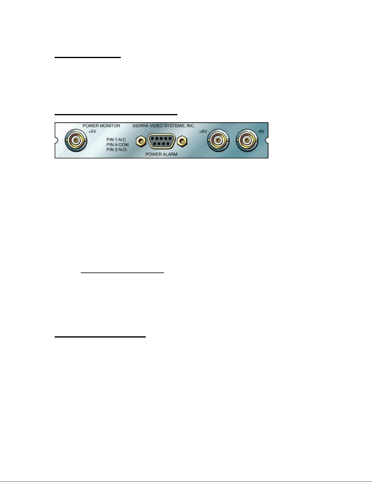
Peripheral Connections
The rear panel provides the following signal connections to the user:
+5V - This BNC connector serves as a voltage monitoring point for the frames +5V DC power
supply. It has a source impedance of 100 Ohms and can be grounded indefinitely.
+8V - This BNC connector serves as a voltage monitoring point for the frames +8V DC power
supply. It has a source impedance of 100 Ohms and can be grounded indefinitely.
-8V - This BNC connector serves as a voltage monitoring point for the frames -8V DC power supply.
It has a source impedance of 100 Ohms and can be grounded indefinitely.
POWER ALARM - This female DB-9 connector serves as power failure alarm monitoring point for
the frames +5V, -5V,& -8V DC power supplies. It provides connections to a floating SPDT
contact set capable of passing 0.25A. The contact pins are coupled to ground through capacitors
to suppress EMI. These are the pin functions:
Pin
No. Function
1 Normally Closed(when all supplies are OK) Contact
2 Normally Open(when all supplies are OK) Contact
3-5 Ground
6 Common Contact
7-9 Ground
Internal Jumpers
The current loads placed on the frames power supplies can be adjusted by moving internal jumpers on the
Power Monitor module. J1 through J3 act in an additive fashion; providing up to 1A of +5V supply
loading. Unused jumper blocks can be pushed onto any single pin when not in use. Check the
specifications for your DigiLinx frame to determine your supply loading requirement(if any).
J1 - Shorting pins 1 and 2 with the supplied jumper block adds a 1/3rd Ampere load to the +5V power
supply.
J2 - Shorting pins 1 and 2 with the supplied jumper block adds a 1/3rd Ampere load to the +5V power
supply.
Power Monitor User’s Guide 2
Page 3

J3 - Shorting pins 1 and 2 with the supplied jumper block adds a 1/3rd Ampere load to the +5V power
supply.
J4 - Shorting pins 1 and 2 with the supplied jumper block adds a 0.08 Ampere load to the -8V power
supply.
J5 - Shorting pins 1 and 2 with the supplied jumper block adds a 0.08 Ampere load to the -8V power
supply.
J6 - Shorting pins 1 and 2 with the supplied jumper block adds a 0.08 Ampere load to the +8V power
supply.
J7 - Shorting pins 1 and 2 with the supplied jumper block adds a 0.08 Ampere load to the +8V power
supply.
Specifications
Output Signals DC power supply voltages(+5V, +8V, -8Vas labeled)
Output Signal Connector BNC female
Output signal impedance 100 Ohms resistive
Output loading 0 Ohms indefinitely without damage,>10K Ohms for 1% measurement
accuracy
Alarm Contact Ratings 0.25A closed, 100V open, 50V to ground
+5V current loads 5, 7.5, 15 Ohms and no load
+8V current loads 50, 100 Ohms and no load
-8V current loads 50, 100 Ohms and no load
Power Consumption 5V; 0, 0.33A, 0.66A, or 1A(selectable) plus 100mA(fixed)
8V; 0, 80, or 160mA
-8V; 0, 80, or 160mA
Operating Temperature Range 0 to 50 C non,condensing
Operating Humidity Range 0 to 95% RH
Power Monitor User’s Guide 3
 Loading...