

Page 1

User Manual
RAZ-IR NANO
Thermal Camera System
User Manual
Sierra Pacific Innovations Corp
6620 S Tenaya Way, Las Vegas, NV 89113 USA
Telephone: 702.369.3966
Facsimile: 702.369.3977
Email: [email protected]
Internet: www.rax-ir.com
© Sierra Pacific Innovations Corp, 2009
Publication No: RAZ-IR® NANO UM 008
Page 2
User Manual
2
The Quality Management System of the manufacturer is approved to ISO9001:2000 for the design and manufacturing, stockholding, in-house
repair and site servicing of non-contact temperature measuring instrumentation.
Sierra Pacific Innovations Corp reserves the right to make changes and improvements on any of the products described in this manual without
prior notice.
RAZ-IR NANO Thermal Camera complies with current European directives relating to electromagnetic compatibility and
safety. (EMC directive 89/336/EEC; Low voltage directive 73/23/EEC).
Copyright
© Sierra Pacific Innovations Corp. All rights reserved worldwide. No parts of the products may be reproduced, transmitted, transcribed or
translated into any language or computer language in any form or by any means, electronic, magnetic, optical, manual or otherwise, without the
prior written permission of Sierra Pacific Innovations Corp.
This manual must not, in whole or part, be copied, photocopied, reproduced, translated or transmitted to any electronic medium or machine
readable form without prior consent, in writing, from Sierra Pacific Innovations Corp.
Page 3

User Manual
3
Table of the Contents
Table of Contents.....................................................................................................................................................................................................3
Introduction ..............................................................................................................................................................................................................4
Precautions.............................................................................................................................................................................................................. 4
Maintenance ............................................................................................................................................................................................................4
Calibration and Repair Philosophy ..........................................................................................................................................................................5
Technical Support ....................................................................................................................................................................................................5
Feedback to Us .......................................................................................................................................................................................................5
System Overview.....................................................................................................................................................................................................5
System Configuration ..............................................................................................................................................................................................5
Technical Specification ............................................................................................................................................................................................6
System Features .....................................................................................................................................................................................................8
Parts Described .......................................................................................................................................................................................................9
Inserting / Removing the Mini SD Memory Card ................................................................................................................................................... 11
Battery Charging....................................................................................................................................................................................................12
Introduction to Buttons...........................................................................................................................................................................................13
Quick Start Guide ..................................................................................................................................................................................................14
Using the Camera..................................................................................................................................................................................................14
Video Output..........................................................................................................................................................................................................50
Transferring Data from the Camera to PC............................................................................................................................................................. 50
Installing the Camera USB Driver to PC................................................................................................................................................................ 50
Controlling the Camera through RS232 Communication Protocol ........................................................................................................................53
Troubleshooting .....................................................................................................................................................................................................64
Emissivity............................................................................................................................................................................................................... 64
Typical Emissivity Values.......................................................................................................................................................................................66!
Page 4

User Manual
4
Introduction
This publication provides the necessary information required to safely operate the RAZ-IR® N ANO Thermal Camera.
It is important to fully check all equipment with which you have been supplied.
The equipment should be used, maintained and serviced by suitably trained personnel, capable of carefully following the procedures and
guidelines given in this User Manual.
All User Manuals and leaflets should be read thoroughly before proceeding with operation of the equipment.
It is also advisable that all User Manuals and Instruction Leaflets supplied are kept readily available, for reference when the equipment is in
general use.
Precautions
The following precautions must be adhered to at all times and must be considered in addition to any advised precautions issued at the relevant
worksite or work area.
• Keep the RAZ-IR® NANO Thermal Camera steady during operation.
• Do not use the RAZ-IR® NANO Thermal Camera in temperature exceeding its working and storage temperature ranges.
• Do not direct the RAZ-IR® NANO Thermal Camera at very high intensity radiation sources such as the sun, carbon dioxide lasers or
arc welders etc.
• Do not expose the RAZ-IR® NANO Thermal Camera to dust and moisture.
• When the RAZ-IR® NANO Thermal Camera is not in use or is to be transported, ensure that the unit and its accessories are stored in
the protective carry case.
• Do not obstruct the ventilation holes or loudspeaker on the camera body.
• Do not restart the camera until 15 seconds after switching it off.
• Do not throw, knock or vibrate intensely the camera and its components in order to keep them from damage.
• Do not attempt to open the camera body, as this action will void the warranty.
• Keep the SD memory card for the exclusive use of the camera.
The RAZ-IR® NANO Thermal Camera utilizes a Lithium Ion (Li-Ion) rechargeable battery pack. The following safety precautions must be
adhered to at all times to ensure the safe use of this equipment.
• Do not disassemble or attempt to open the battery under any circumstances.
• Do not expose the battery to fire or high temperatures.
• Do not short circuit the battery.
• Do keep the battery dry.
• Charging of the battery should only be carried out using the recommended or supplied charging device.
Maintenance
To ensure that the RAZ-IR® NANO Thermal Camera is kept in good working condition and remains fully operational, the following guidelines
should be adhered to at all times.
Non-optical surfaces
The non-optical surfaces of the camera can be cleaned when required, with a soft cloth dampened with water and a mild detergent.
Optical surfaces
Page 5

User Manual
5
The optical surfaces of the camera lens should only be cleaned when visibly dirty. Care should be taken to avoid touching the exposed lens
surface, as skin acid left behind from fingerprints can be damaging to coatings and lens substrates. Use only a proprietary lens cleaning tissue.
Calibration and Repair Philosophy
Calibration or repair for the instrument can be obtained by either contacting the address/ telephone number on the cover of this User Manual.
Caution
The RAZ-IR® NANO Thermal Camera does not incorporate any user serviceable parts. Never attempt to disassemble or modify the camera.
Opening the unit invalidates the warranty.
Technical Support
Technical support for your Sierra Pacific Innovations Corp Thermal Imaging System can be obtained by either contacting the address /
telephone number on the cover of this User Manual.
Feedback to Us
We have tested and verified the information in this manual to the best of our abilities. Yet as we are committed to continuous development and
progress, you might find features of the product have been changed since the time of printing. Please let us know about any error you find, and
your suggestions for revisions by contacting the address/telephone number on the cover of this User Manual.
System Overview
RAZ-IR® NANO is an affordable yet full functioned IR Thermal Radiometric Camera.
No matter how many infrared thermography cameras you have seen, no matter how rigorous your demand is, the RAZ-IR® NANO will meet or
exceed your needs. Featuring smart structure design, large capacity radiometric IR image and IR video recording, auto focusing, touch screen,
IR fusion and picture-in-picture viewing; it sets a new milestone for affordable IR cameras.
System Configuration
Please ensure that the following items have been correctly supplied:
• IR Camera with visual camera, laser locator
• 11mm IR lens
• 2.47" TFT LCD with high resolution, touch pen
• 2GB Mini SD card & card reader
• Two rechargeable Li-ion batteries
• Battery charger
• AC Adapter & cable
• USB extension cable
• RS232 communication & TV video cable
• USB driver
• IR Analyser® Software
• User manual
• Carry case & strap
Page 6
User Manual
6
Options
• 30mm Tele lens
• 7mm Wide angle lens
• Target Illuminator
• Infrared Remote Controller
• Sun Shield
• Leather Sheath
• Silicon Rubber Protecting Jacket
Technical Specification
Imaging Performance
THERMAL
Detector type:
Uncooled FPA microbolometer (160× 120 pixels, 25µm)
Spectral Range:
8-14µm
Thermal Sensitivity:
≤100mk at 30℃
Field of View/ Focus:
20.6° X 15.5°/ 11mm
Focus:
Automatic or motorized
Electronic Zoom:
X2
VISUAL
Built-in Digital Video:
CMOS Sensor, 1600x1200 pixels, 224 true colors
Image Presentation
External Display:
2.47" TFT LCD with high resolution
Video Output:
PAL/ NTSC
IR fusion:
Visual and IR blending
Man-Machine Communication
Touch Screen:
Present and receive operator’s commands
Buttons:
Respond as per operation
Menu:
Microsoft® Windows style
Measurement
Temperature Range:
-20℃ to 250℃ (350℃ optional)
Accuracy:
±2℃ or ±2% of reading
Measurement Modes:
Auto hot & cold spot, auto alarm live/zoomed image & video;4 movable spots,
4 movable and changeable areas displaying either max, min or average, 2
lines profile, histogram & isotherm band in live/frozen/saved image
Emissivity Correction:
Variable from 0.01 to 1.00 (in 0.01 increment)
Page 7

User Manual
7
Measurement Features:
Automatic correction based on distance, relative humidity, atmospheric
transmission and external optics
Optics Transmission Correction:
Auto, based on signals from sensors
Image Storage
Type:
Removable 2GB Mini SD card & built-in memory
File Format:
JPG with analysis records
Voice Annotation:
Up to 60 seconds
Text Annotation:
Selected from preset texts or Customized
Live Video Recording & Measurement & Storage
Powerful recording up to 30 minutes in Mini SD card
Recording:
Thermal video recording to PC via USB2.0, capacity dependent on PC hard
disk capacity.
Measurement:
Automatic Max & Min temperature
Storage:
In Mini SD card or PC
Laser Locator
Classification Type:
Class 2 semiconductor laser
Power System
Battery Type:
Recharge Li-ion Camcorder battery, field-replaceable
Charging System:
In camera or in battery charger
Battery Operating Time:
Over 4 hours continuous operation
External Power Operation:
AC adapter 110/ 220 VAC, 50/ 60Hz
Environmental Specification
Operating Temperature:
-10℃ to 60℃
Storage Temperature:
-20℃ to 60℃
Humidity:
Operating and storing 10% to 95%, non- condensing
Encapsulation:
IP54 IEC 529 housing
Shock:
Operational: 25G, IEC 68-2-29
Vibration:
Operational: 2G, IEC 68-2-6
Interfaces
USB 2.0:
Real-time image, video data transfer to PC and real-time control of the camera
on PC
RS232 communication:
Control of camera on PC
Physical Characteristics
Housing:
Magnalium
Weight:
0.35KG(including battery) 0.274KG(excluding battery)
Size:
154mmx69mmx45mm
Page 8

User Manual
8
System Features
Unique Features
• IR Fusion technology allows you to overlay the thermal image directly to the corresponding visual image
• 2.0 Megapixels CMOS delivers extremely crisp visual image, assistance of crisper and better fusion image.
• Easily switchable PAL/ NTSC video output simplifies video viewing.
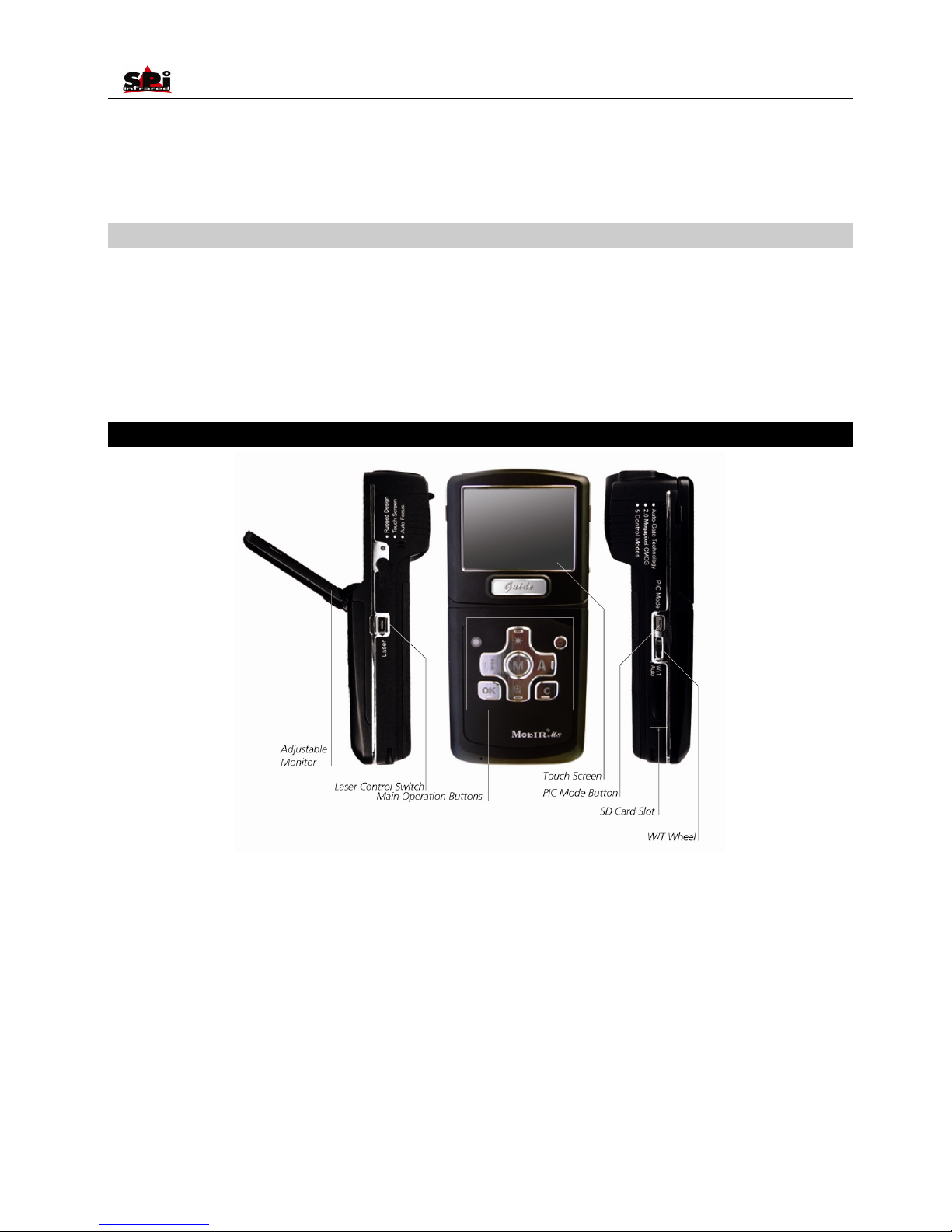
• Camera can be controlled by touch screen, buttons, W/T wheel, USB 2.0 interface, and infrared remote controller, enabling the camera use
in any application.
• Auto focus for both thermal and visual image which can be realized by simply pressing one button.
• Auto gate works as both shutter and intelligent lens cap.
• Internal lens is no longer vulnerable and this special design also makes the optional lens’ assembling easy.
• Real-time radiometric thermal video recording and JPG image storage facilitate further analysis and report generation.
• Ultra large capacity Mini SD memory card and built-in flash memory offer easy in-field storage.
• High-speed USB2.0 interface enables real-time data transfer, live video recording and camera control.
• Windows-style man-machine interface & status display screen showing component status reinforce the user-friendly feature.
• Compact & durable magnalium camera casing raises reliability and operation easiness.
• Robust on board analysis enhances operators’ efficiency & productivity.
• 4 Hours super long working time ensures uninterrupted high efficient work.
Imaging Performance
• Output both thermal and visual video to external display..
• Transfer live thermal video into PC via USB 2.0 cable.
• Zoom in or out thermal image x2.
• Auto or motorized focusing of IR lens.
Temperature Measurement
• Auto calibration ensures high accuracy.
• Auto hot-spot tracing and center-cursor temperature measurement pinpoint the problem.
• Up to 4 spots can be analyzed simultaneously in live or frozen or saved images.
• Up to 4 areas can be analyzed simultaneously in live or frozen or saved images, showing respective Max, Min or Average temperature
within each area.
• Discretional area can be analyzed simultaneously in live or frozen or saved images, showing respective Max, Min or Average temperature
within the area.
• 2 lines analysis can be done in live or frozen or saved images.
• Histogram analysis can be performed on live or zoomed or frozen or saved images.
• Isotherm analysis can be done in live or frozen or saved images.
Image & Video Storage
• Live images can be frozen to be static images to do multiple-spot analysis, multiple-area analysis, discretional area analysis, line analysis
and isotherm analysis.
• Frozen images, comprising radiometric data, infrared image, visual image, voice annotation and text annotation, can be saved into 2GB Mini
SD card or the built-in flash memory in standard JPG format.
Page 9
User Manual
9
• Up to 60-second digital clip of voice can be recorded and saved for each image.
• Mini SD card can accommodate 600 images and the built-in flash memory can store 100 images.
• Live thermal video can be recorded in Mini SD card and PC via USB cable. Temperature measurement and different kinds of analysis can
be done on recorded video.
Image Playback
• Images/videos saved into Mini SD card or the built-in flash memory can be replayed on the camera.
• Temperature measurement and different kinds of analysis can be done on replayed images.
• Voice annotation, text annotation and visual images saved together with thermal images can be replayed as well.
• Recorded thermal video can be replayed on board or on PC.
• Images/video saved in Mini SD card and the built-in flash memory can be downloaded to PC for further analysis and report generation with
software Guide IrAnalyser®
Parts Described
Page 10
User Manual
10
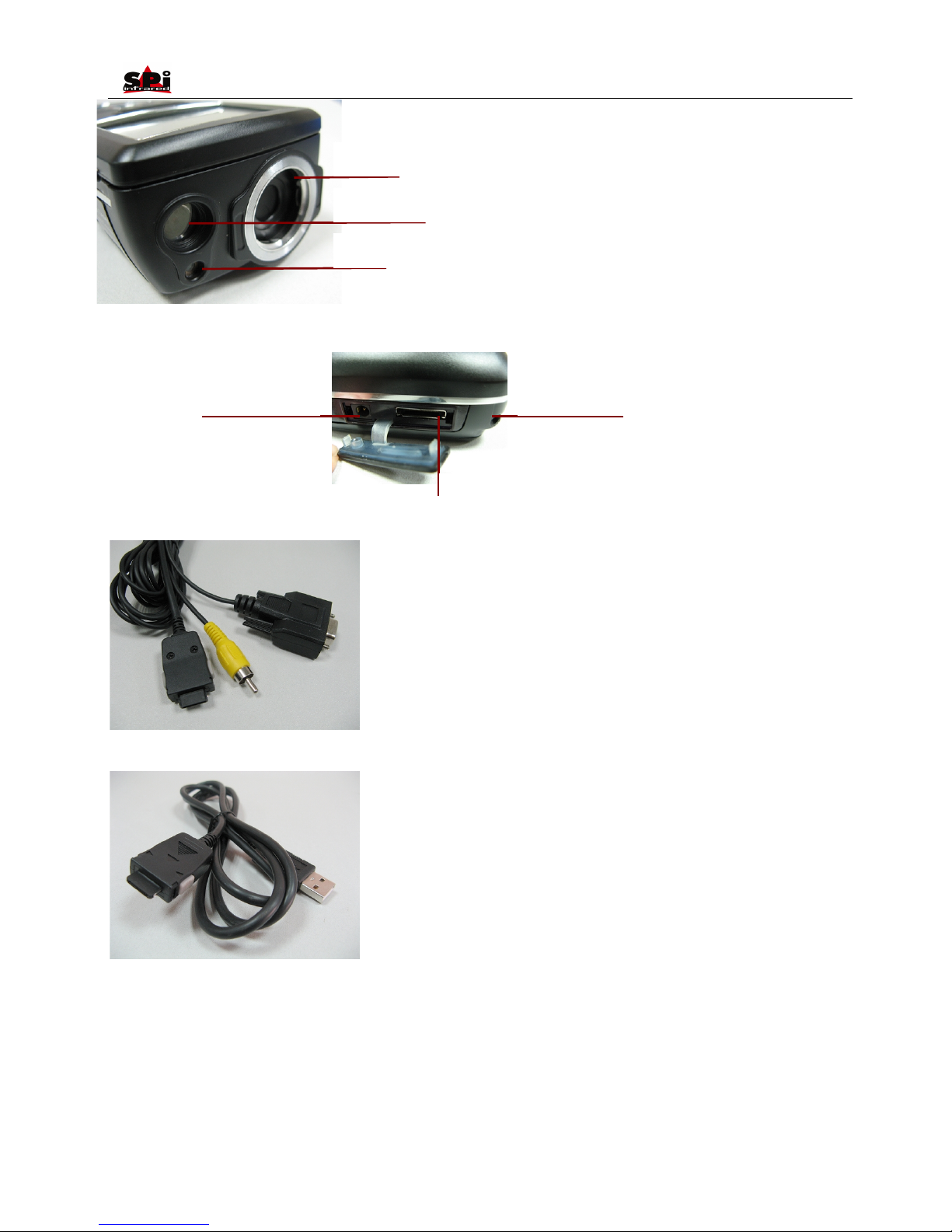
RS232 and TV Video cable: Interfaces
from the left to right are respectively:
TV Video/RS232 interface to the TV
Video /RS232 interface on camera, TV
Video interface to a TV Video display
device, and RS232 interface to PC,
USB extension cable: Interfaces from the
left to right are respectively: Interface to
the camera USB2.0 interface to a USB
interface on PC.
IR Lens
Visual camera
Laser
Touch pen slot
USB interface & RS232 and TV Video cable
Power interface
Page 11
User Manual
11
Camera with cables: from the top down and from left to right, the camera is connected with USB extension cable, AC adapter cable and RS232/
TV video cable.
• If connecting the RS232 interface of RS232/ TV video cable to a PC with RS232 communication port, you can view the live video on the
video display device and meanwhile control the camera on PC via RS232 communication protocol.
• If only connecting the USB extension cable to a PC with USB2.0 interface and running the corresponding menu commands of Guide
IrAnalyser® software (e.g. sub-command Device Video of command Video under menu File), you can view the live thermal video on PC,
control the camera on PC and also record live thermal video into PC.
Inserting / Removing the Mini SD Memory Card
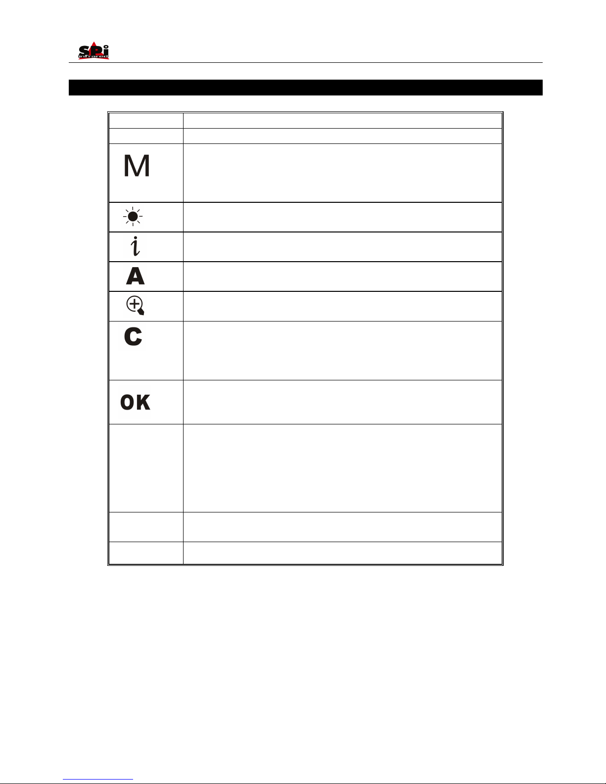
• To insert or remove a Mini SD memory card, open the Mini SD memory card cover.
• To insert a Mini SD memory card, slide the card with the terminals pointing downwards and the obverse outwards till you hear a slight sound,
as shown in the figure below.
• To remove a Mini SD memory card, press the card downwards and then release it. It will bounce to be pulled it from the camera.
Notes for the Mini SD memory cards:
• Ensure that saving or opening of images is complete before removing the Mini SD memory card.
• Do not use the Mini SD memory card as a common removable disk for storing other information than images or video taken by the camera.
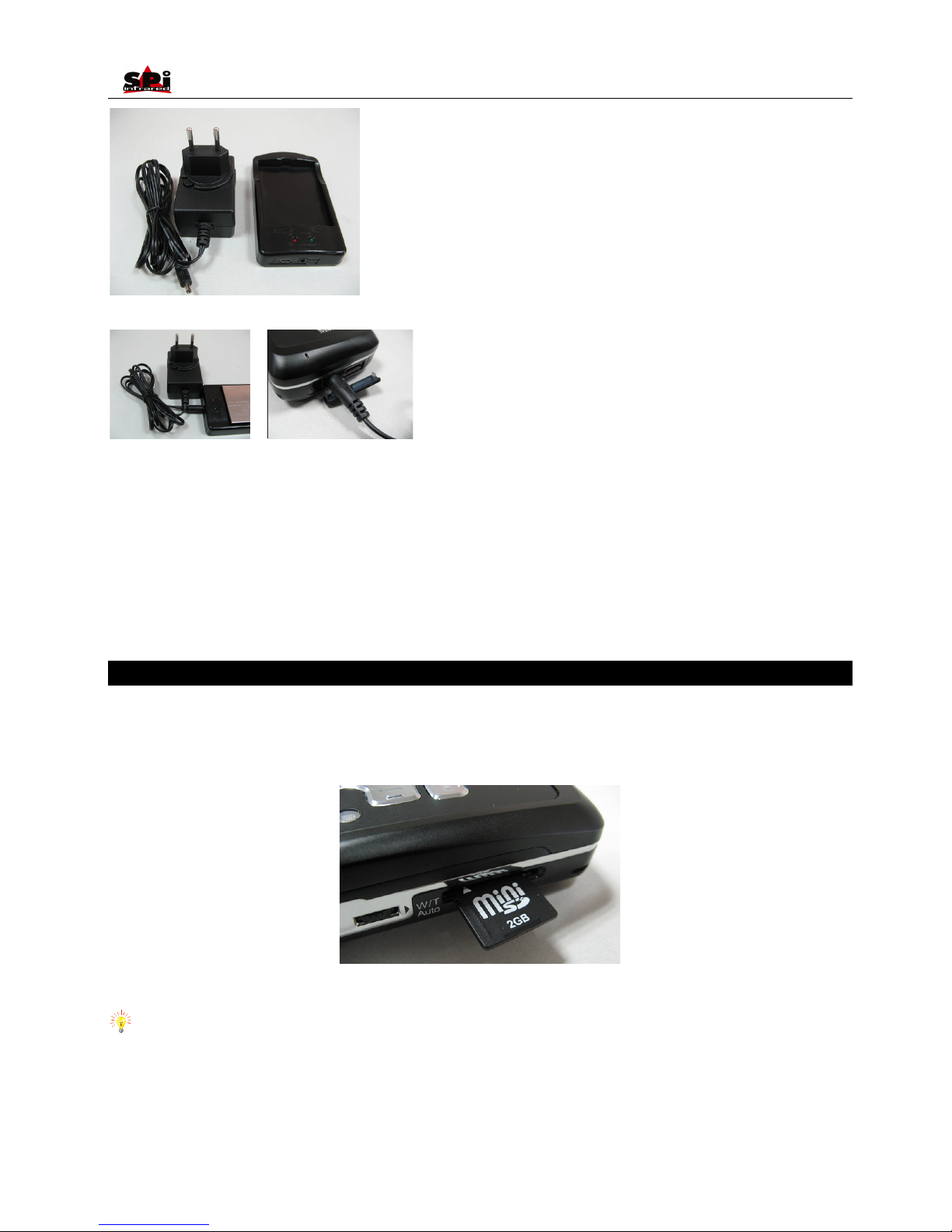
AC adapter and battery charger
Note: AC adapter is valid for both
battery charger and camera itself.
Page 12

User Manual
12
Battery Charging
Two methods are available to charge the battery.
• Charging in an external battery charger
• Charging in the imbedded battery charger
Charging in an external battery charger
• Insert the battery into the battery charger, the charge lamp (green) will light
• Connect the charger plug to a wall outlet (96-250VAC), the charge lamp (red) will light and charging will begin
• When connect to the power resource, if the charge lamp (green) turns to be orange, it indicates the battery is not full and need to be charged;
if the charge lamp (green) remains green, it indicates the battery needn’t to be charged
• Once the battery is fully charged the charge lamp (green) will turn from orange to green
• The approximate charge time is 240 minutes for full charge
Charging in the imbedded battery charger
• Connect the AC adapter plug with the camera
• Connect the AC adapter plug to a wall outlet (96-250VAC)
• When the camera is power off, the red indicator light on the top-left per side of Button will keep blinking during charging and extinguish
when the battery is fully charged.
• When the camera is power on, press Button to bring out information bar, an icon flash will keep blinking during charging and turn to icon
battery when the battery is fully charged.
• The approximate charge time is 240 minutes for full charge
Note:
• When charging the battery in the imbedded battery charger, Button Power is unavailable
• Charging time may vary from the battery condition or the environment temperature
• It is normal that battery and the charger get heated during charging process.
• Plz ensure battery full charge and discharge at the first 3 times use.
• When not use, it’s strongly suggested to store the battery with battery level only a half of full battery capacity.
Additional Information
• The battery shall be charged in temperature between 0℃ and +45℃
• Never dispose the battery to fire or try to heat the battery
• Do insert the battery with the terminals connected to correct polarity
• Do not short circuit the battery by directly connecting the metal terminals
• Ensure that no metal objects touch the battery terminals
• Do not direct the battery at bright sunshine or put the battery in an over-heated environment
• Always remove the battery from the equipment or charger when it is not in use. Store the battery in a cool, dry place
• All rechargeable batteries gradually lose their charge over time when they are left in storage. If the battery is to be left in storage or for
a period of non-use, a 'top-off' charge should be carried out prior to use
• Do stop using the battery when it heats abnormally or emit peculiar smell or distorts
Page 13
User Manual
13
Introduction to Buttons
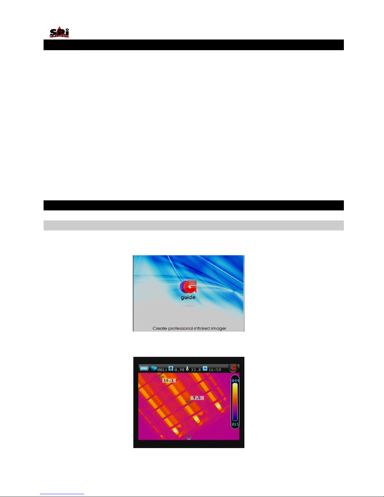
BUTTON
FUNCTION
On/ Off
Power on/off
To bring out / hide main menu
To enter menus and its sub menus
To select one sub menu or option under menu
To confirm parameter setup/ option selected
(Up)
To bring out temperature setup menu to adjust Tmax, palette, Tmin if necessary
Button Up-direction
(Left)
To bring out / retract information bar
Button Left-direction
(Right)
To bring out analysis bar in live thermal image
Button Right-direction
(Down)
To zoom in/out
Button Down-direction
To cancel one sub menu or option under menu
To exit menu
To return to the live thermal image when image is frozen
To perform a NUC manually when there is no menu on live image
To select one sub menu or option under menu
To freeze and store live image when menu does not appear on screen.
PIC mode
To switch among the three display modes: Thermal image alone, Visual image alone and IR
fusion image, if the fusion function is set as “on”.
To replay the visual image and IR fusion either in dynamic live status/frozen/ replay status, vice
versa.
When menu does not appear on screen, keep it depressed for three seconds to switch
between Auto and Manual mode
W/T Wheel
Rotate the W/T wheel to adjust focus manually
Press the W/T wheel inwards and then release to start auto focus in dynamic live status
Laser
To activate laser locating function
Page 14
User Manual
14
Quick Start Guide
• Ensure that the battery is fully charged and the SD memory card is inserted in the camera
• Keep button “On/ Off” depressed for 3 seconds to switch on the camera.
• Wait till the boot screen image disappears and uncover lens cap. Non Uniformity Calibration (NUC) is performed automatically.
• Aim the camera at the target.
• Rotate the W/T wheel manually to adjust the focus to get clear thermal image or you can press the W/T wheel to get clear thermal image
automatically.
• Press button“☼”and release it instantly and then adjust Tmax, Tmin and palette if necessary.
• Press button “PIC Mode”to switch to live visual image and fusion image.
• In visual image, still rotate the W/T wheel to manually focus or you can press the W/T wheel to automatically get clear visual image.
• Press button“PIC Mode”for 3 seconds to switch between manual and auto modes.
• Press button “OK” to freeze the live image.
• Press button “OK” again to store the frozen image into SD memory card or built-in flash memory of the camera.
• Press button “C” to return to the live thermal image.
Using the Camera
Powering on the camera
Keep button On / Off depressed for 3 seconds to power on the camera.
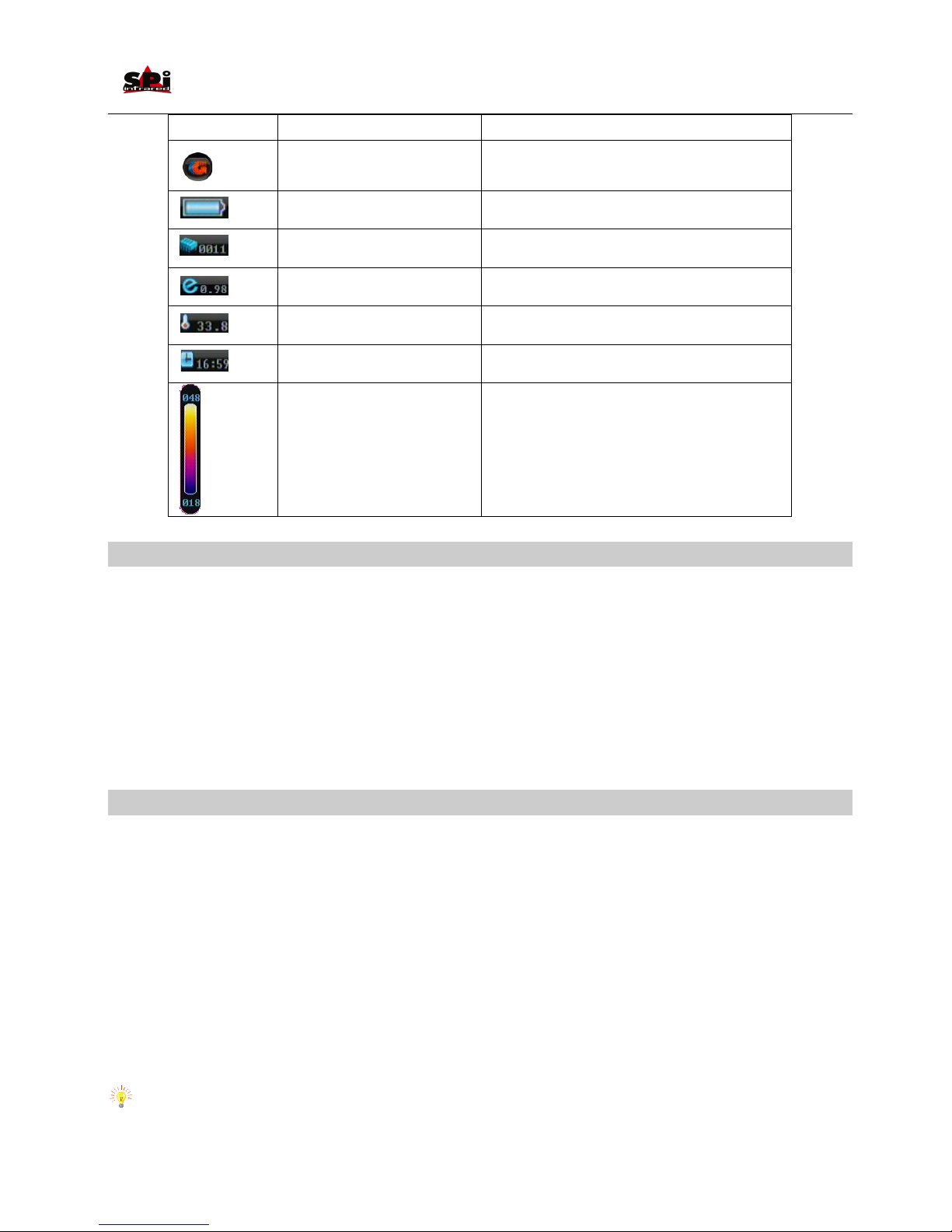
Then the loading image and boot-up flash as shown below appear on the screen.
After the boot-up flash disappears, live image as shown below is displayed, with Guide logo and temperature setup menu lying at the right side
of the screen.
Page 15
User Manual
Icon
Significance
Function
Guide logo
Bring up the information bar upon clicking by the touch
pen
Power
Display battery power capability
Memory
Display the number of saved image
Emissivity
Display the set target emissivity
Ambient temperature
Display the ambient temperature
Time
Display the time
Temperature setup menu
Display the temperature unit, Tmax, Tmin and palette for
the current image.
Non Uniformity Calibration (NUC)
• After powering on the camera and the boot-up flash disappears, the camera will automatically perform 3 times of Non Uniformity Calibration
(NUC) after 5 seconds, 25 seconds, and 45 seconds from switch on.
• While it is working, the camera will automatically perform NUC at a regular frequency. NUC allows the camera to automatically clean up the
live image of noise, ensuring normalisation and sharpness of the live image.
• If necessary, manual NUC can be performed. To perform a NUC manually, keep button C depressed .During the NUC the live image pauses
temporarily, whilst auto gate is placed in front of the lens.
• This process takes only a couple of seconds, however for best results, please ensure that camera is pointed at a low temperature uniform
surface or the lens cap.
Focusing
Thermal camera focusing
There are two methods available to adjust focus: manual and automatic.
Before focusing, ensure the lens cap is uncovered and there is no icon chosen in live thermal image, no matter whether there are menu or dialog
box displayed or not.
• To manually focus, aim the lens at the target and then rotate the W/T wheel to get clear image.
• To automatically focus, press the W/T wheel inwards and then release.
Visual camera focusing
There are two methods available to adjust focus: manual and automatic.
• Press button “PIC Mode” to switch from thermal image to visual image.
• To manually focus, aim the lens at the target and then rotate the W/T wheel to get clear visual image.
• To automatically focus, press the W/T wheel inwards and then release.
Note: When the temperature difference between the target and its surroundings is not great, it is advisable to focus manually to get a clear
image of the target.
Page 16
User Manual
16
Setting the temperature range
There are 2 methods available to set the temperature range: Auto and Manual.
• To switch between the 2 modes, when there is no icon chosen in live thermal image, keep button “PIC Mode”depressed for 3 seconds and
then release it to switch between the 2 modes. The prompt “Auto” or “Manual” will appear in the up left corner of the screen.
• In each mode, when there is no menu displayed in live thermal image, press button Up for an instant to select the temperature setup menu
at the right side of the image. Or press button M to enter main menu and then press button Left or Right to highlight button Tools, press
button up to highlight submenu Palette and press button M to bring up the temperature setup menu. Then press the up and down button to
change the Tmax value, and press the button Left and Right to change the Tmin value.
• If changing values of Tmax and Tmin in Auto mode, the camera will immediately switch to manual mode.
• Altering values of Tmax and Tmin actually changes the display effect of a certain palette.
• The standard temperature range of the camera is -20 to 250°C.
• After changing the option values, press button OK to save the setting and exit the menu.
• Using the touch pen can also do the above operations. Firstly, click the palette with touch pen to change option values of Tmax and Tmin.
Click the palette again with touch pen to change the palette. Click the palette thirdly to save and exit Tmax, Tmin and palette change mode.
Basic Temperature Measurement
For basic temperature measurement, firstly ensure that a suitable temperature range is set and that the image is in focus. Two methods are
available, dynamic real-time temperature measurement and static temperature measurement.
Dynamic real-time temperature measurement
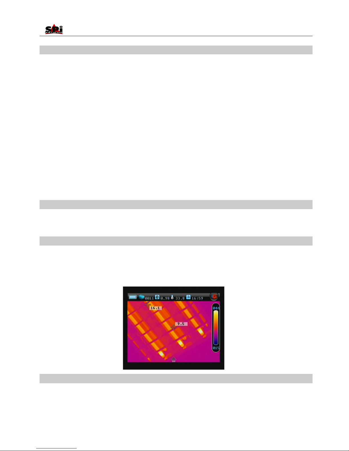
• There are two cursors on the live thermal image. One is always fixed in the centre of the image; the other is always tracing the hottest spot of
the image.
• Two temperatures are present on the thermal image. The one always in the middle of the image indicates the center temperature, the other
one always tracks and indicates the maximum scene temperature.
Static Temperature Measurement
• This method is available when there is no menu displayed in frozen or saved thermal images.
• Keep the camera steady when you have the image in focus, press Button OK to freeze the live image;
• Static temperature measurement can be done on a saved image as well.
Page 17
User Manual
17
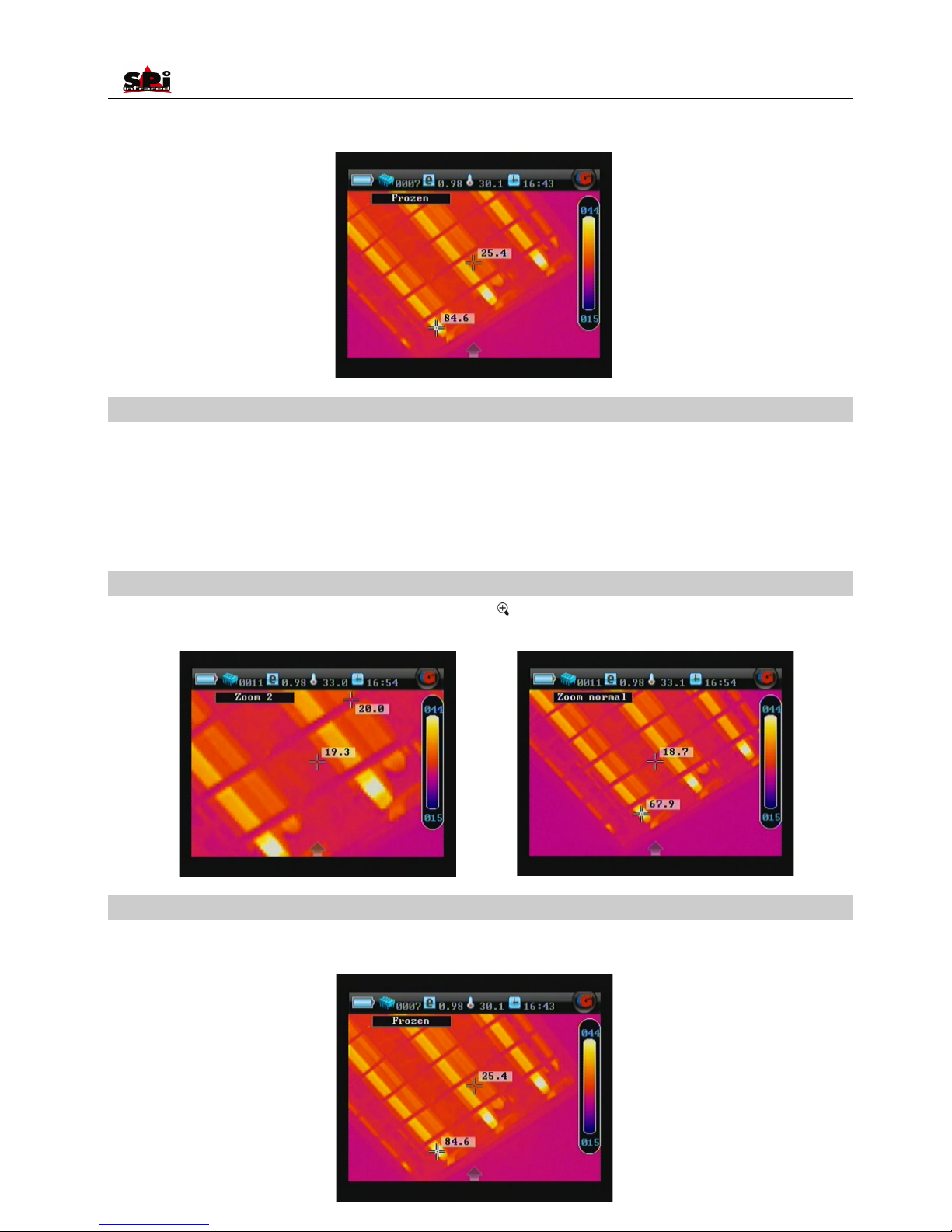
• Move the center cursor by pressing the buttons Up, Down, Left and Right. The temperature varies along with the cursor moving. While the
place and temperature of the hottest spot never changes.
Adjusting temperature range of frozen/ saved image
Temperature range of a frozen or saved image can be changed as well to adjust the image quality.
When there is no menu displayed in the frozen or saved thermal image, click the palette with touch pen first, then you can change option values
of Tmax , Tmin , and the palette with touch pen, changing the respective values of the options. Or press button M to enter main menu and then
press button Left or Right to highlight button Tools, press button Up to highlight submenu Palette and press button M to bring up the temperature
setup menu.
Image zoom
When there is no menu displayed in live thermal image, press the button to zoom in or out the image continuously from x1 to x2, with the
current magnification shown at the up left corner of the screen.
Pausing live image and save image
• Keep the camera steady when you want to freeze the image, and then press Button OK to freeze the live image. Prompt Frozen is shown at
the up left corner of the screen.
Page 18
User Manual
18
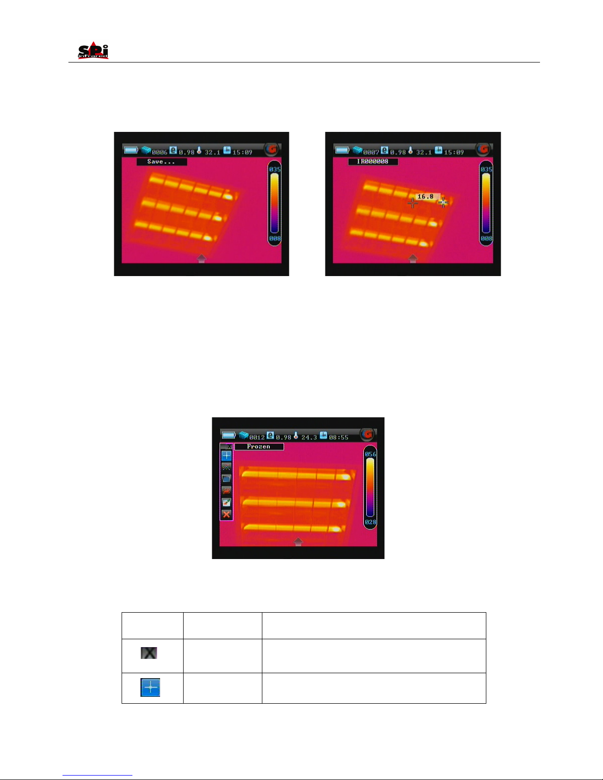
• Press button OK again to save the frozen image directly into the memory media (built-in flash memory or mini SD memory card). Then name
of the saved image “IR******” will be displayed at the up left corner of the screen for 2 seconds.
• Or you can do multiple kinds of operation on the frozen image before saving it into the memory media, such as static temperature
measurement, temperature range adjustment, spot analysis, line analysis, area analysis, isotherm analysis, discretional area analysis,
recording and playback of voice annotation, adding text annotation, etc.
• When there is no menu displayed on the frozen image, you can do static temperature measurement and temperature range adjustment as
per instruction aforesaid.
• To do the left operation listed below, press button M to enter main menu and then press button Left or Down to highlight menu Tools, press
button Up to highlight submenu Analysis and press M to bring up the Analysis bar. The operation is also can be done by touch pen to click
each icon to select a certain one. The detailed analysis operation will be introduced in separate sections later.
• Functions of the icons in the toolbar are listed as below. Press button OK can toggle between each icon. Or simply use the touch pen to click
each icon to select. For detailed operation of analysis function by buttons, please refer to the RS232 software operation introduction in this
user manual.
Icon
Significance
Function
Exit command
Exit the analysis toolbar
Spot analysis
Do spot analysis
Page 19
User Manual
19
Line analysis
Do line analysis
Area analysis
Do area analysis
Isotherm analysis
Do isotherm analysis
Discretional area
analysis
Do discretional area analysis. Use the touch pen to outline certain
target in any shape.
Delete analysis
object
Delete selected analysis object or delete analysis object in the
opposite order of the object is added.
• Spot analysis, line analysis, area analysis, isotherm analysis, and discretional area analysis will be introduced in following separate
sections.
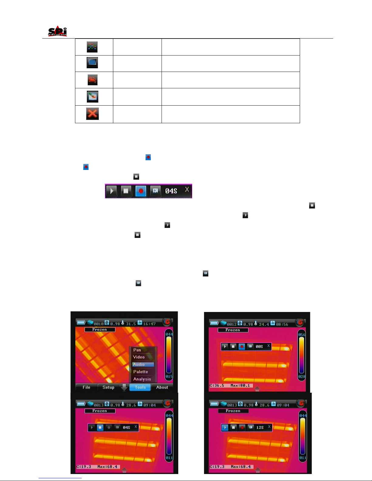
• If voice annotation is required with the image, freeze the image and then press button M and select the menu Tools to choose the sub menu
Audio function. Select the icon Start recording with the touch pen. Or press the button OK to toggle between the icons, highlight the icon
Start recording and then press button M to select it. Now you can start recording annotation and view the time of recording in the timing
box. Meanwhile the icon Stop recording is highlighted.
· Up to 60 seconds of voice annotation can be saved for each image. To stop recording at any time, press the icon Stop recording . Once it
reaches 60 seconds, recording will stop automatically. At the meantime, icon Play recording is highlighted.
• To replay the recording, select the icon play recording by clicking it with the touch pen or pressing the button M to highlight directly.
When replaying, the icon Stop recording is highlighted. You can stop replaying at any time.
• If the recording is not satisfied, repeat the above mentioned operations.
• If the recording is satisfied but no need to insert any text annotation to the image, press button C to exit and then press button OK to save
the recording with the image into the memory media, with file name “IR******” displayed in the status bar under image screen.
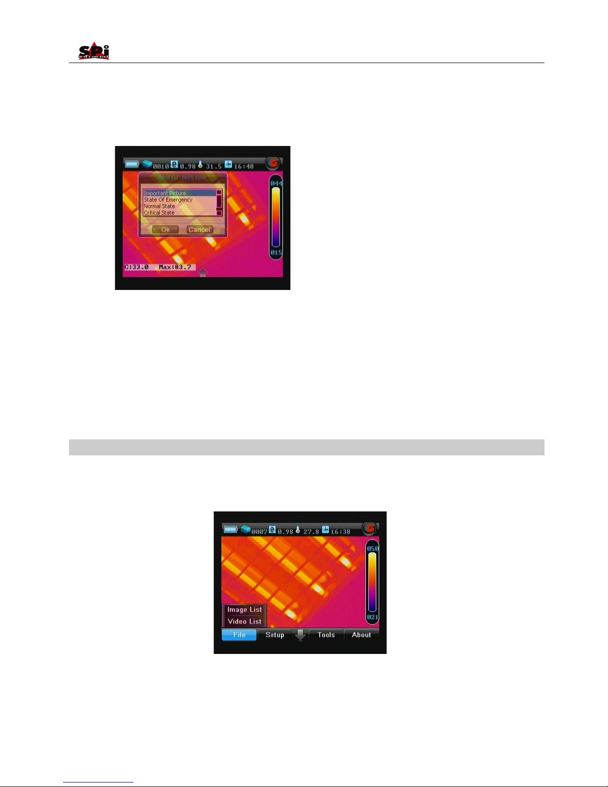
• To insert text annotation to a frozen image, select the icon Text Annotation with the touch pen or press button OK to toggle between the
icons, highlight the icon Text annotation and then press button M to select it. Then the annotation dialog box appears in the image
screen. To select one out of the preset annotations, click it with the touch pen or press button Up or Down to highlight a certain text
annotation. Press button Ok to toggle between Ok and Cancel. Press button M to confirm saving the text annotation or cancel.
Page 20
User Manual
20
• Press button C to save and exit the voice annotation and text annotation mode. Press button Ok to save the frozen image with voice
annotation and text annotation into the memory media if any, with file name “IR******” displayed on up left corner of screen.
• Frozen images are saved as JPEG files in the memory media. After saving an image, the camera will switch to live thermal image status.
• Press button C to exit the frozen image and return to the live thermal image status.
• If the mini SD memory card or the built-in flash memory is fully filled with images, the respective prompt “SD full” or “Storage full” will appear
in the status bar under the image screen when you try to save a new image. If fail to save an image, the prompt “Save error” will appear in
the status bar under the image screen.
Replaying saved images
Saved images can be replayed on or deleted from the camera.
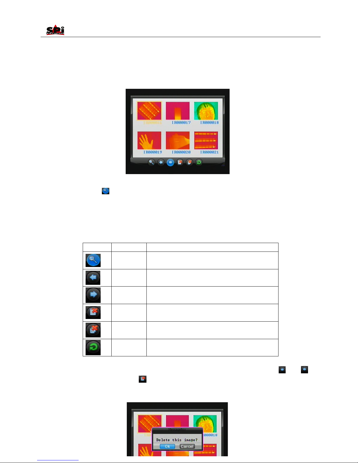
• Bring up the main menu and the select option File list under submenu File with the touch pen. Or press the button M when there is no menu
displayed in live image to bring up the main menu, with option File list highlighted. Press button Up and Down to select the option File list.
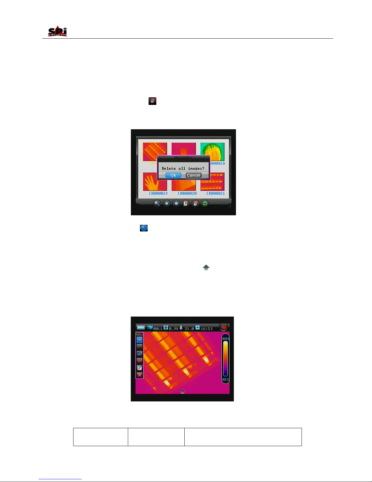
• Now the thumbnail images are displayed in the screen (6 per screen) and the file toolbar is displayed under the image screen. The first
image and icon are highlighted.
Page 21
User Manual
21
· To toggle between the 6 images within one screen, click them with the touch pen or press buttons Up, Down, Left and Right to select a certain
image, choose the icon by clicking it with the touch pen. Or you can press button OK to highlight the icon first and then press the
button M to select the icon.
• To toggle between each icons of the file toolbar, click them with the touch pen or press button OK. After highlighting a certain icon, pressing
the button M will choose the icon and execute the corresponding function.
• Functions of the icons of file toolbar are listed below:
Icon
Significance
Function
Open file
Open a selected image
Up direction
Press it to turn to the previous screen
Down direction
Press it to turn to the next screen
Delete file
Delete a selected image
Delete all
Delete all the saved images from the current memory media
Exit command
Exit the replay status and back to live thermal image
• If more than 6 images are saved, the images will be displayed in next page. To toggle between the pages, select icon or icon .
• To delete a selected image, choose the icon . Then a dialog box “Delete this image?” will appear on the screen. Choose button M to
delete it or button C to cancel. The two buttons can be chosen either by clicking with the touch pen or by pressing button M to select, or
button C to cancel.
Page 22
User Manual
22
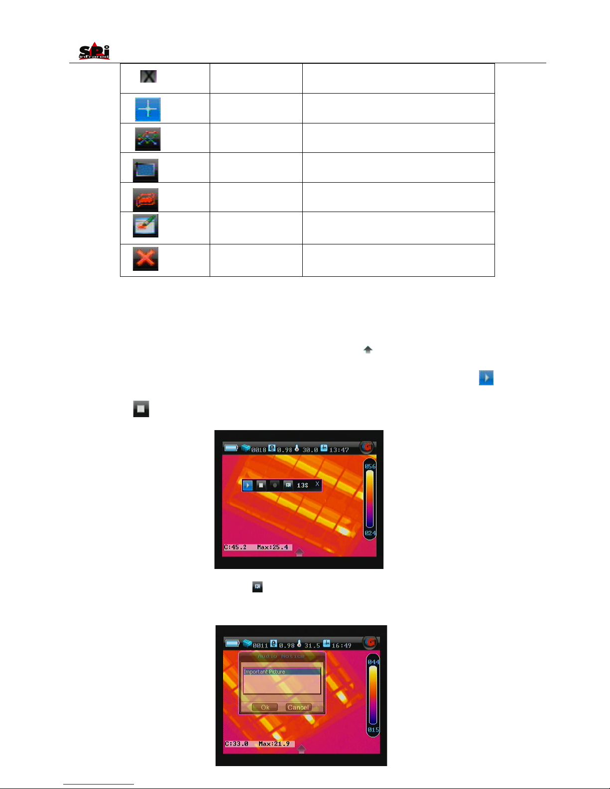
• To delete all the saved images, choose the icon . Then a dialog box “Delete all images?” will appear on the screen. Choose button Ok to
confirm or button C to cancel deletion. The two buttons can be chosen either by clicking with the touch pen or by pressing button M to select,
or button C to cancel.
• To open a selected image, choose the icon .
• Multiple kinds of analysis can be performed on saved image, such as static temperature measurement, spot analysis, area analysis, line
analysis, isotherm analysis, visual image replay, IR fusion image replay, voice annotation replay, text annotation replay etc.
• To do static temperature measurement, please refer to the sections Static temperature measurement.
• To do analysis on frozen image, bring up the main menu by clicking icon at the bottom of the screen with the touch pen or pressing
button M. Press button Left or Right to highlight menu Tools. When Tools is highlighted, press button Up to highlight submenu Analysis and
press button M to select it. Or, you can just click the menu Tools and click Analysis to enter Analysis menu. The toolbar offers similar options
to the frozen toolbar, whose functions are introduced below. Clicking each icon with the touch pen can select them respectively. Or press
button Ok to highlight one option first and press button M to select the highlighted option.
•
• Functions of the icons of Analysis toolbar are listed below:
Icon
Significance
Function
Page 23
User Manual
23
Exit command
Exit the analysis toolbar
Spot analysis
Do spot analysis on the replayed image
Line analysis
Do line analysis on the replayed image
Area analysis
Do area analysis on the replayed image
Isotherm analysis
Do isotherm analysis on the replayed image
Discretional area
analysis
Do Discretional area analysis on the replayed image
Delete analysis object
Delete selected analysis object or delete analysis
object in the opposite order of the object is added.
• Spot, line, area, isotherm and discretional area analysis are the same as that in live thermal image. For detailed operation, please refer to
the corresponding section below.
• To replay the visual image and IR fusion, press button PIC Mode.
• To replay the recorded voice annotation, bring up the main menu by clicking icon at the bottom of the screen with the touch pen or
pressing button M. Press button Left or Right to highlight menu Tools. When Tools is highlighted, press button Up to highlight submenu
Audio and press button M to select it. Or, you can just click the menu Tools and click Audio to enter it, choose icon to start voice
replaying . Then you can hear the voice and view the time in the timing box of voice annotation. To stop replaying before its ends by
choosing icon stop voice recording.
• To view the recorded text annotation, choose icon to replay text annotation. Then the recorded text will be displayed in a dialog box on
the image screen. To close the dialog box, choose the button OK by clicking it with the touch pen or pressing button M.
Page 24
User Manual
24
• To exit the replay status, choose icon to exit command or press button C. Then the live thermal image will be resumed.
Note:
• The icon Start voice replaying is not available when the replayed image does not include voice annotation
• The icon Replay text annotation is not available when the replayed image does not include text annotation
Visual image
The camera offers visual imaging function. Visual image can be switched from its corresponding thermal image either in dynamic live
status/frozen/ replay status, vice versa.
• This can be done easily by pressing button PIC Mode directly.
• Focus of the visual camera can be adjusted as well. Generally the focus is suitable. If necessary, you can adjust it manually by rotating W/T
wheel or automatically by pressing W/T wheel.
• To switch to thermal image, press button PIC Mode again.
IR fusion image
• This function is available in live/ frozen/saved images.
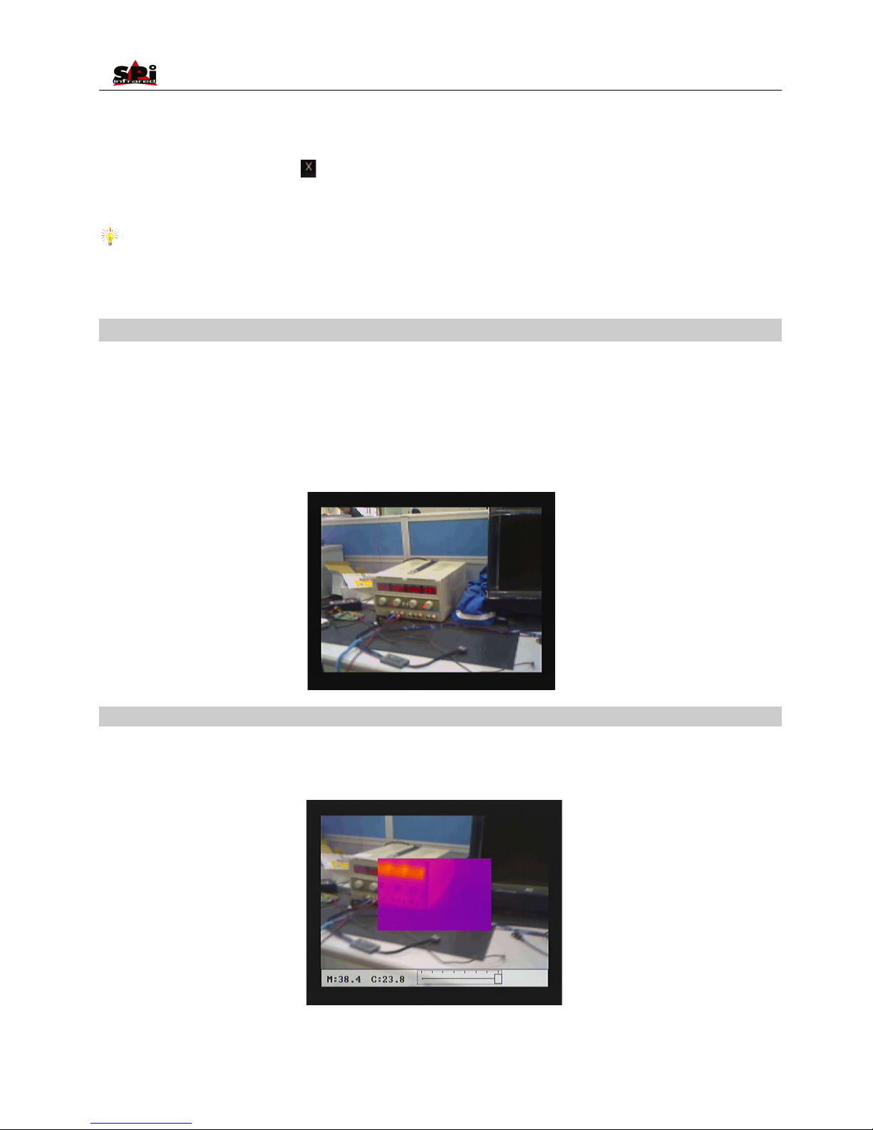
• Press function button PIC Mode and release it instantly to switch among the three display modes: Thermal image alone, Visual image alone
and IR fusion image. The images below show the mode IR fusion image.
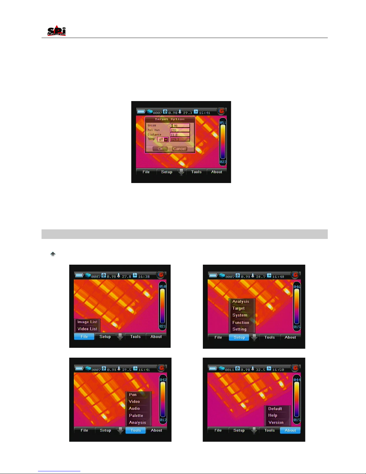
The tool bar at the bottom of the screen is to adjust the transparency of the fusion part. Press button Left or Right to adjust its value and to
Page 25
User Manual
25
change the transparency from 0 to 100%. The area size won’t change.
Parameter “Distance” can be set to achieve the best IR fusion image. Display the Menu, then enter menu “Setup”, select sub-menu “Target”,
press button “OK” to switch to option “Distance”, set its value (meters), then the program will adjust the IR fusion image to the best. Or click the
“e” icon in the information bar, set the value in the pop-up window.
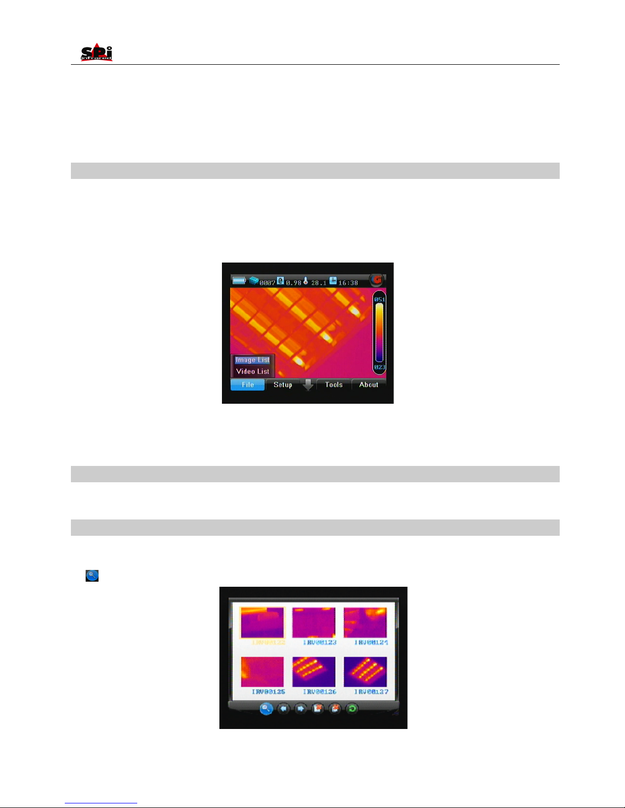
Main Menu Introduction
• The camera offers a user-friendly Windows-style main menu. The main menu is brought up on the screen by either clicking the icon Arrow
at centre bottom of the screen or pressing button M when there is no menu displayed in the screen
Page 26
User Manual
26
• The submenus can be navigated by either clicking with the touch pen or pressing button Left or Right.
• In each submenu, options are navigated by either clicking with the touch pen or pressing button up or down. The highlighted option is
confirmed by clicking with the pen or pressing button M.
• To exit the menu system at any time and return to a live thermal image, press button C or click the icon Arrow at centre bottom of the screen.
File
Saved images can be replayed on or deleted from the camera.
• Bring up the main menu and the select option File list under submenu File with the touch pen. Or press the button M when there is no menu
displayed in live image to bring up the main menu, with option File list highlighted. Press button Up and Down to select the option File list.
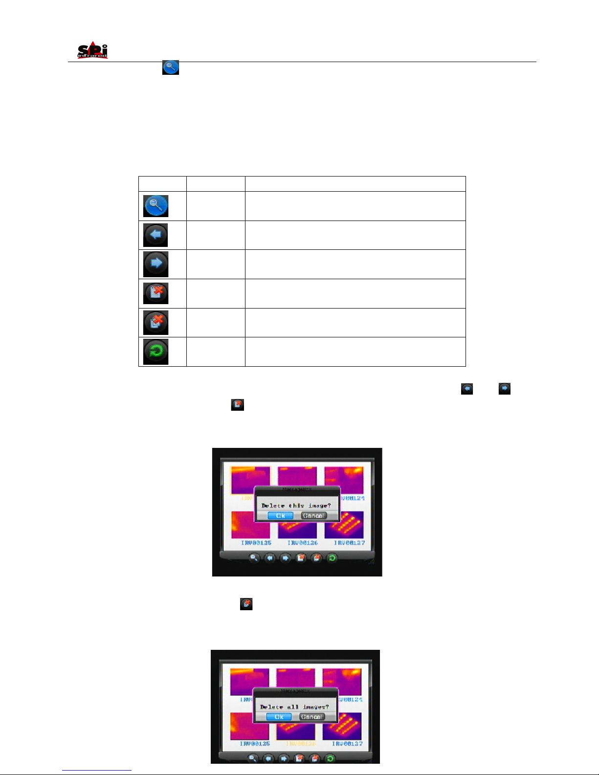
• Two options Image List and Video List are present on the screen. Clicking them respectively with the touch pen or moving the button “Up” or
“Down” can toggle between them.
• Image List: Allows for the replay of saved images.
• Video List: Allows for the replay of saved videos.
Option Image List
• The function is just as introduced as in the above passage about replaying saved image.
Option Video List
• Live video recording method will be introduced in the later “Video” description section.
• The thumbnail videos are displayed in the screen (6 per screen) and the file toolbar is displayed under the screen. The first video and icon
are highlighted.
· To toggle between the 6 videos within one screen, click them with the touch pen or press buttons Up, Down, Left and Right to select a certain
Page 27
User Manual
27
video, choose the icon by clicking it with the touch pen. Or you can press button OK to highlight the icon first and then press the
button
M to select the icon.
• To toggle between each icons of the file toolbar, click them with the touch pen or press button OK. After highlighting a certain icon, pressing
the button M will choose the icon and execute the corresponding function.
• Functions of the icons of file toolbar are listed below:
Icon
Significance
Function
Open file
Open a selected video
Up direction
Press it to turn to the previous screen
Down direction
Press it to turn to the next screen
Delete file
Delete a selected video
Delete all
Delete all the saved videos from the current memory media
Exit command
Exit the replay status and back to live thermal image
• If more than 6 videos are saved, the videos will be displayed in next page. To toggle between the pages, select icon or icon .
• To delete a selected video, choose the icon . Then a dialog box “Delete this video?” will appear on the screen. Choose button M to
delete it or button C to cancel. The two buttons can be chosen either by clicking with the touch pen or by pressing button M to select, or
button C to cancel.
• To delete all the saved images, choose the icon . Then a dialog box “Delete all videos?” will appear on the screen. Choose button Ok to
confirm or button C to cancel deletion. The two buttons can be chosen either by clicking with the touch pen or by pressing button M to select,
or button C to cancel.
Page 28
User Manual
28
• To open a selected image, choose the icon .
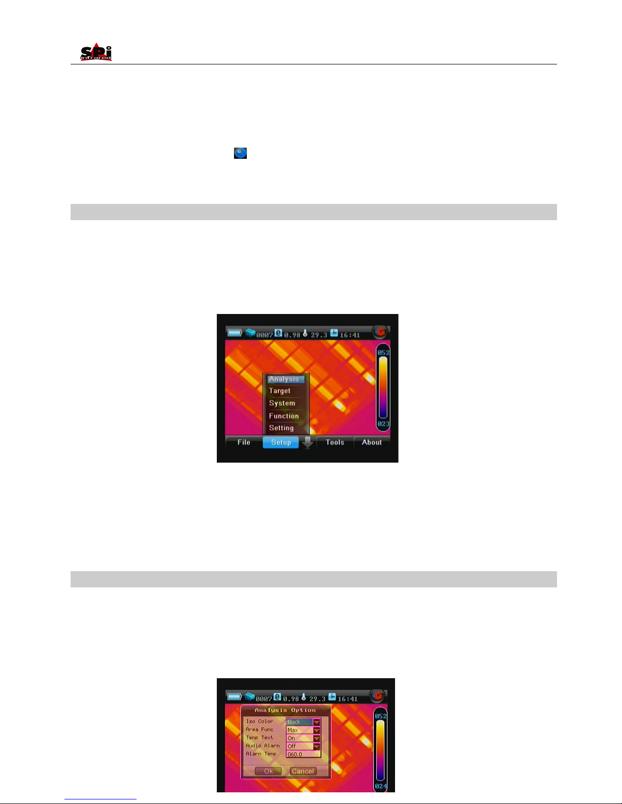
Menu Setup
• Camera setup can be set for the camera. Click the icon up arrow at the below center of the screen with the touch pen to bring up the main
menu and then click the submenu Setup. Or press the M button to bring up the main menu and move the button left or right to select the
submenu Setup.
• Five options Analysis, Target, System, Function and Setting are present in the screen. Clicking them respectively with the touch pen or
pressing the button “Up” or “down” can toggle between them.
• Analysis: Allows for temperature analysis parameters for live and zoomed images to be set up
• Target: Allows for temperature measurement parameters of the target to be set up
• System: Allows for system parameters to be set up
• Function: Allows for some camera functions to be set up
• Setting: Allows for other parameters of the camera to be set up
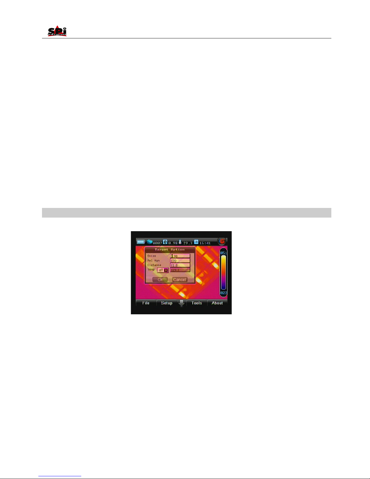
Option Analysis
• Click option Analysis with the touch pen or press the button M to select it. Then the Analysis dialog box appears on the screen.
• Clicking each option box with the touch pen or pressing button OK can toggle between the options. Moving the button up or down can alter
values of the option. Moving the button left or right can toggle between each digit of the option values if the values contain several digits. If
there are several values to choose from for an option (e.g. IsoColor: Black, Green, White), clicking the values respectively with the touch pen
can also change the option values.
Page 29
User Manual
29
• To save the change, choose button OK or press the M button on the keyboard; to cancel the change, choose button Cancel or press the C
button on the keyboard. Then the dialog box will be closed and the original image status will be resumed.
• Button OK and button Cancel can be selected by the touch pen directly or by pressing M button first and then pressing C button on the
keyboard.
• IsoColor: To choose a certain color for isotherm, black, white or green.
• AreaFunc: To set the temperature type of areas in area analysis, maximum, minimum or average.
• AudioAlarm: To activate or inactivate the audio alarm for live thermal images.
• AlarmTemp: To set the scene temperature threshold above which the audio alarm will sound.
• Temp Text: To display or hide temperature value of center point and hottest point.
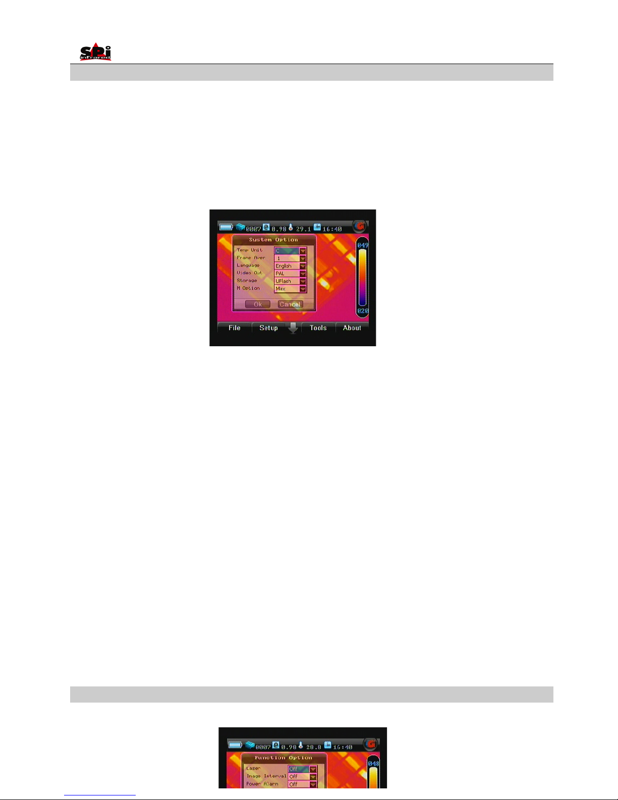
Option Target
• Click option Target with the touch pen or press the button M to select it. Then the Target dialog box appears on the screen.
• Clicking each option box with the touch pen or pressing button OK can toggle between the options. Moving the button up or down can alter
values of the option. Moving the button left or right can toggle between each digit of the option values.
• Emiss: To set emissivity value between 0.01 and 1.00.
• RelHum: To set relative humidity percentage value between 0 and 100.
• Distance: To select distance from target (meters).
• Tamb: To set a ambient temperature or to display real-time ambient temperature. When it is “On”, you need to manually set a suitable
ambient temperature. When it is “Off”, the camera will sense ambient temperature automatically.
• Choose button OK or press the M button on the keyboard to save the change; choose button Cancel or press C button on the keyboard to
cancel change. Then the dialog box will be closed and the original image status will be resumed.
Page 30
User Manual
30
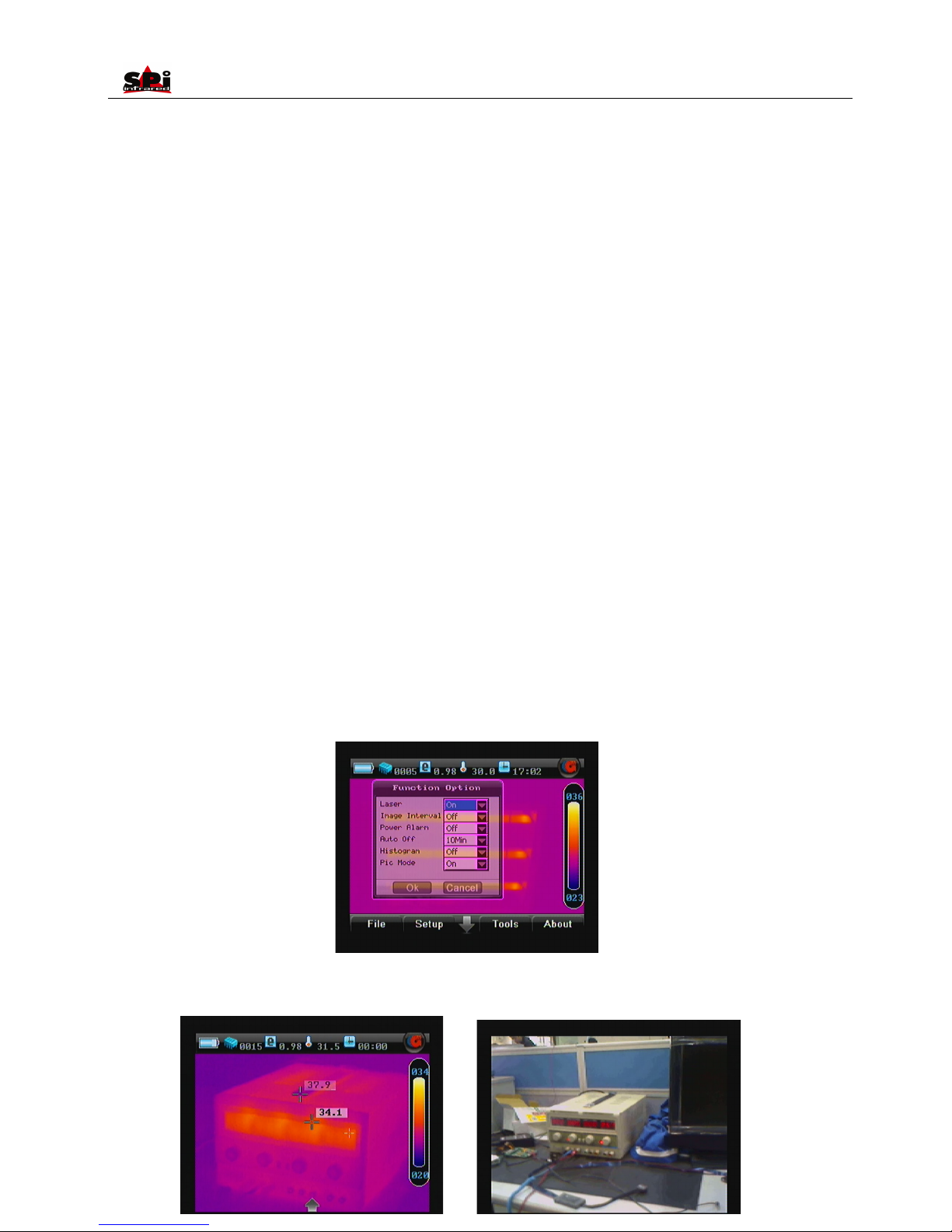
Option System
Click option System with the touch pen or press the button M to select it. Then the System dialog box appears on the screen.
• Clicking each option box with the touch pen or pressing button OK can toggle between the options. Clicking each value respectively with the
touch pen or moving the button up or down can alter values of the option. Moving the button left or right can toggle between each digit of the
option values if the values contain several digits.
• TempUnit: To set the temperature unit for measurement, degrees Celsius or Fahrenheit.
• FrameAver: To set the number of frames for frame averaging algorithm to freeze image.
• Language: To select the language for man-machine communication.
• VideoOut: To turn on or off the video output function. PAL and NTSC can be selected as per requirements. Off means only the VGA output
is available.
• Storage: To choose the memory medium where to save files. If SD card is inserted in the camera, the default medium is SD card. But you
can switch to the built-in flash memory as per need. To switch between the two memory media, you can either set UFlash for Storage here or
click the icon shown in the memory media bar under the image screen.
• M Option: To display the max temperature in the screen if set it as “Max”, or displays the min temperature in the screen if set it as “Min”.
Also there are two options for the temperature alarm function, one is max, the other is min. When you set this M option as max, it means that
the alarm is for high temperature alarm, when the temperature is exceeding the set value, the camera will give alarm. When you set it as min,
it means that the alarm is for low temperature alarm, when the temperature is lower than the set value, the camera will give alarm.
• Choose button OK or press the M button on the keyboard to save the change; choose button Cancel or press C button on the keyboard to
cancel change. Then the dialog box will be closed and the original image status will be resumed.
Option Function
• Click option Function with the touch pen or press the button M to select it. Then the Function dialog box appears on the screen.
Page 31
User Manual
31
• Clicking each option box with the touch pen or pressing button OK can toggle between the options. Clicking each value respectively with the
touch pen or moving the button up or down can alter values of the option.
• Laser: To turn on or off the laser locator.
• Image Interval: To set the value of Image Interval to be 15sec, 30sec, 60sec, 5min. Then the camera will start capturing images as per the
value you set.
• PowerAlarm: To turn on or off the power alarm function. If setting On, the power alarm will sound every one minute when the battery is low.
• Auto Off: To turn on or off the auto off function. Never means the camera will never turn off automatically; 10Min, 30Min or 60Min means the
camera will automatically turn off if there is no operation in successive 10 minutes, 30 minutes or 60 minute intervals. No operation occurs
when there is no use of the VGA LCD screen, no operation of joystick or buttons, and no menu or dialog box displayed on the screen.
• Histogram: To display or close histogram of live, frozen or saved images.
• Pic Mode:
This function is available in live or zoomed or frozen or saved images.
Bring up the main menu, select option Pic Mode under submenu Function either by the touch pen or by pressing button OK, and then set its
value to be ON. Save the setup and exit the menu. Now this function is activated.
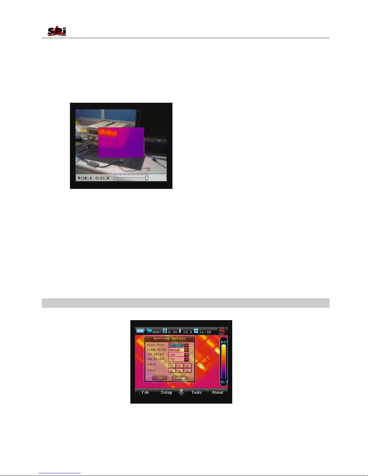
Press function button Pic Mode and release it instantly to switch among the three display modes: Thermal image alone, Visual image alone
and Fusion picture.
Page 32
User Manual
32
The tool bar at the bottom of the screen is to adjust the transparency of the fusion part. Press button Left or Right to adjust its value and to
change the transparency from 0 to 100%. The area size won’t change.
To turn off this function, bring up the main menu, select option Pic Mode under submenu Function either by the touch pen or by pressing OK,
and then set its value to be OFF. Save the setup and exit the menu. Now this function is inactive.
When this function is inactive, pressing function button Pic Mode will switch between the two modes Thermal image alone and Visual image
alone
• Choose button OK or press the button M to save the change; choose button Cancel or press button C directly to cancel change. Then the
dialog box will be closed and the original image status will be resumed.
Option Setting
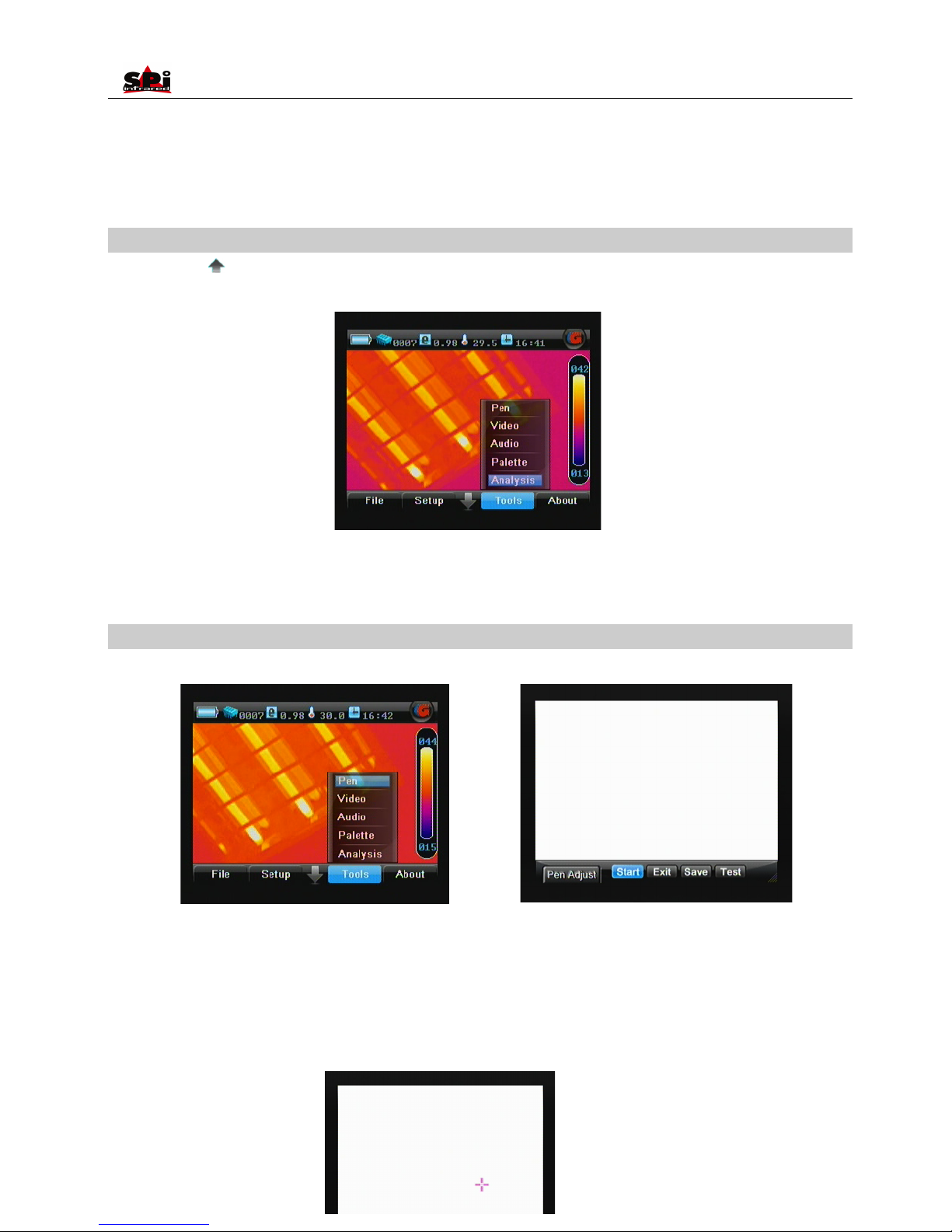
• Click option Setting with the touch pen or press the button OK to select it. Then the Default dialog box appears on the screen.
• Video Freq: To set the video frequency of the camera
• Image Arith: To set infrared image quality of the camera
• LCD BLight: To set LCD back light time of the camera
Page 33
User Manual
33
• KEY BLight: To set light time of the button on the keyboard
• Y/M/D: To set date for the camera. After setup, date of the camera will automatically update.
• H/M/S: To set time for the camera. After setup, time of the camera will automatically update.
Menu Tools
• Click the icon “ ” at the bottom the screen with the touch pen to bring up the main menu and then click the submenu Tools. Or press the
“Menu” button to bring up the main menu and press “Left” or “Right” button to select the submenu Tools.
• Four options Calibration, Video, Audio, Palette and Analysis are present in the screen. Clicking them respectively with the touch pen or
press “Up” or “Down” button can toggle between them.
Option Pen
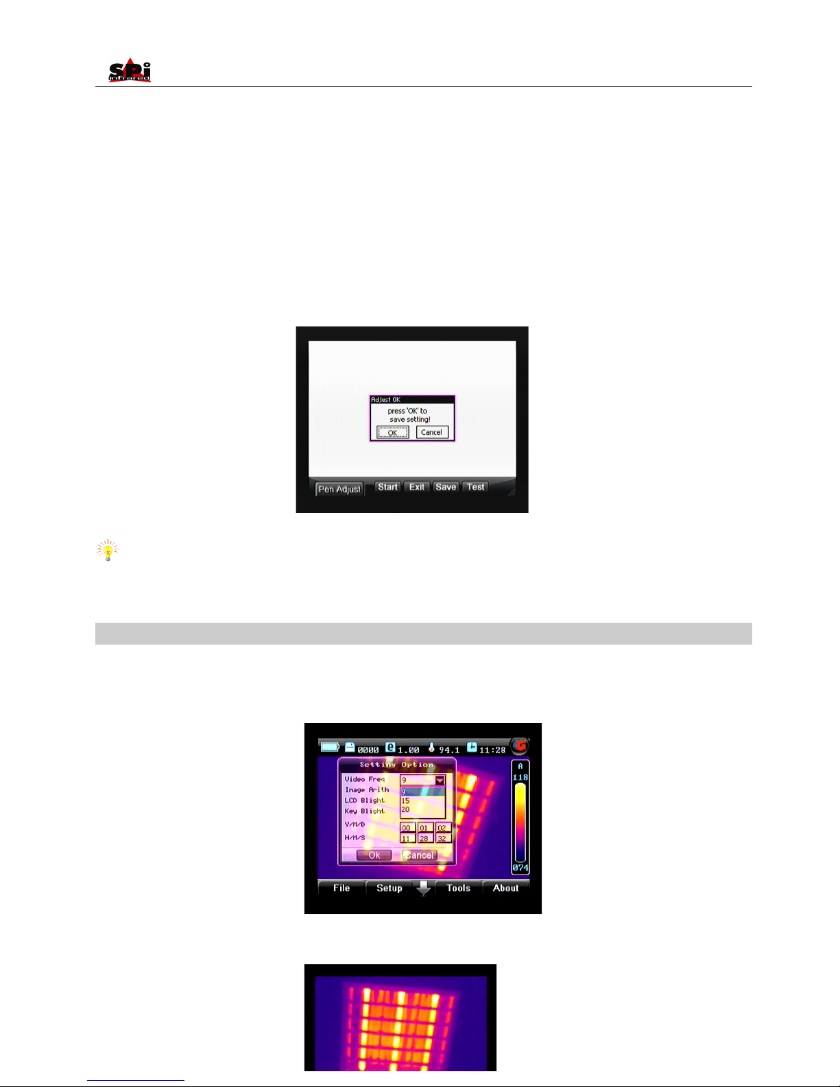
• Click option Pen with the touch pen or press the “OK” button to select it. Then the Pen Adjust interface appears on the screen.
• 4 buttons Start, Exit, Save and Test are available in the interface. Pressing button “Left” or “Right” can toggle between them. Clicking with
the touch pen can select them respectively.
• Select button Start to start adjustment. Then a cursor appears at the left top corner of the screen, click its center with the touch pen; then a
cursor appears in the center of the screen, click its center with the touch pen as well; finally a cursor appears at the right bottom of the
screen, click its center with the touch pen, too. Now the adjustment succeeds and a dialog box appears to prompt the success. Press the
button “OK” or click “OK” on the screen with the touch pen to save the adjustment.
Page 34
User Manual
34
• If adjustment fails, the cause may be that the touch pen did not click on the cursor centers, a dialog box will appear to indicate failure. Then
repeat the operation above until the adjustment succeeds.
• To save the ultimate coordinates of the pen after adjustment, select button “Save”. To test the adjustment result, select button Test, draw
anything with the touch pen on the screen and observe whether the cursor moves accordingly with the pen. If so, adjustment has done well.
Now select button “Save” to save the ultimate coordinates of the pen after adjustment. Then the pen and cursor will respond to each other
accurately.
• Select button “Exit” or press button “C” to exit the interface and return to the live thermal image.
Note: In the adjustment process, improper adjustment may cause the touch pen not to work well. Thus it is strongly recommended to use
functional buttons in this process.
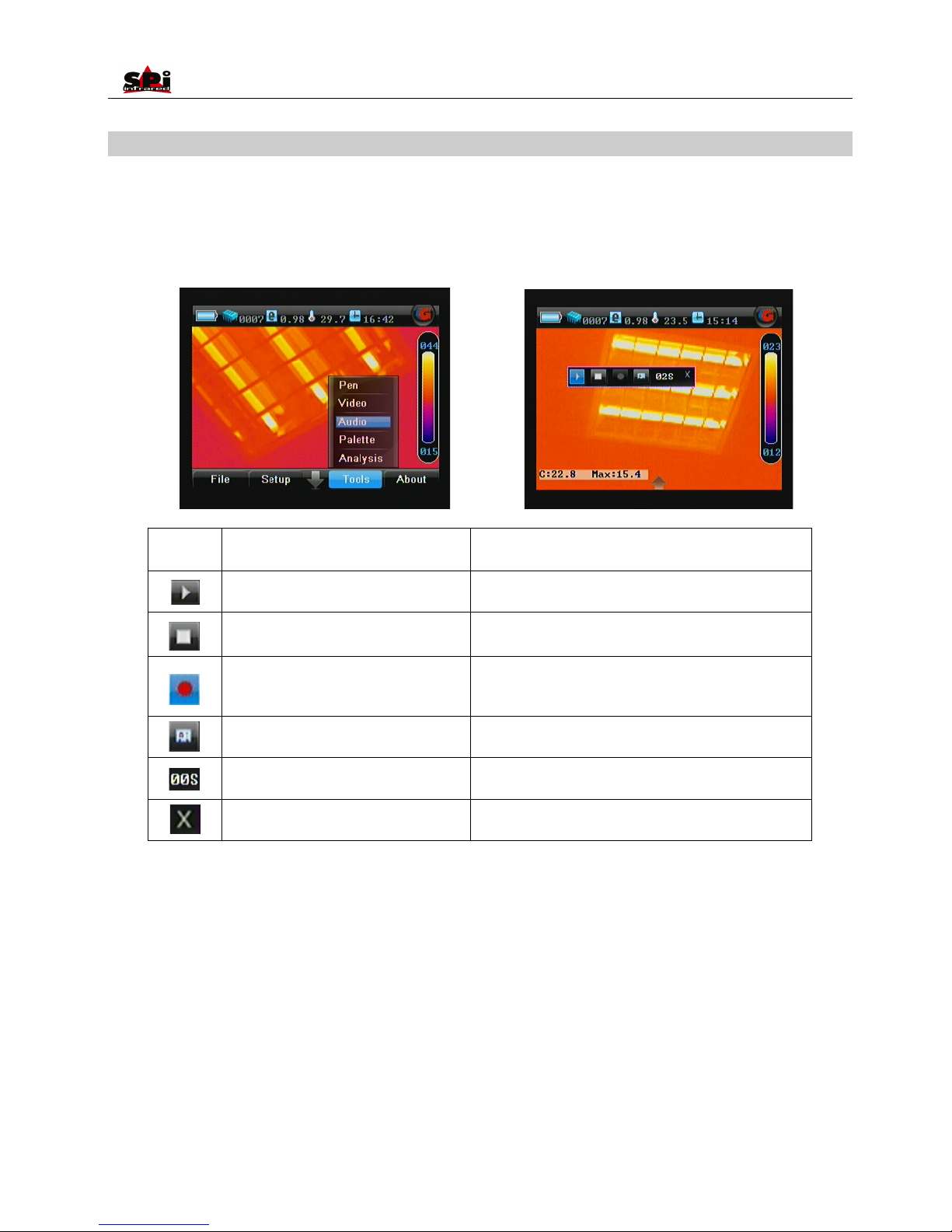
Option Video
• Live video recording can be performed.
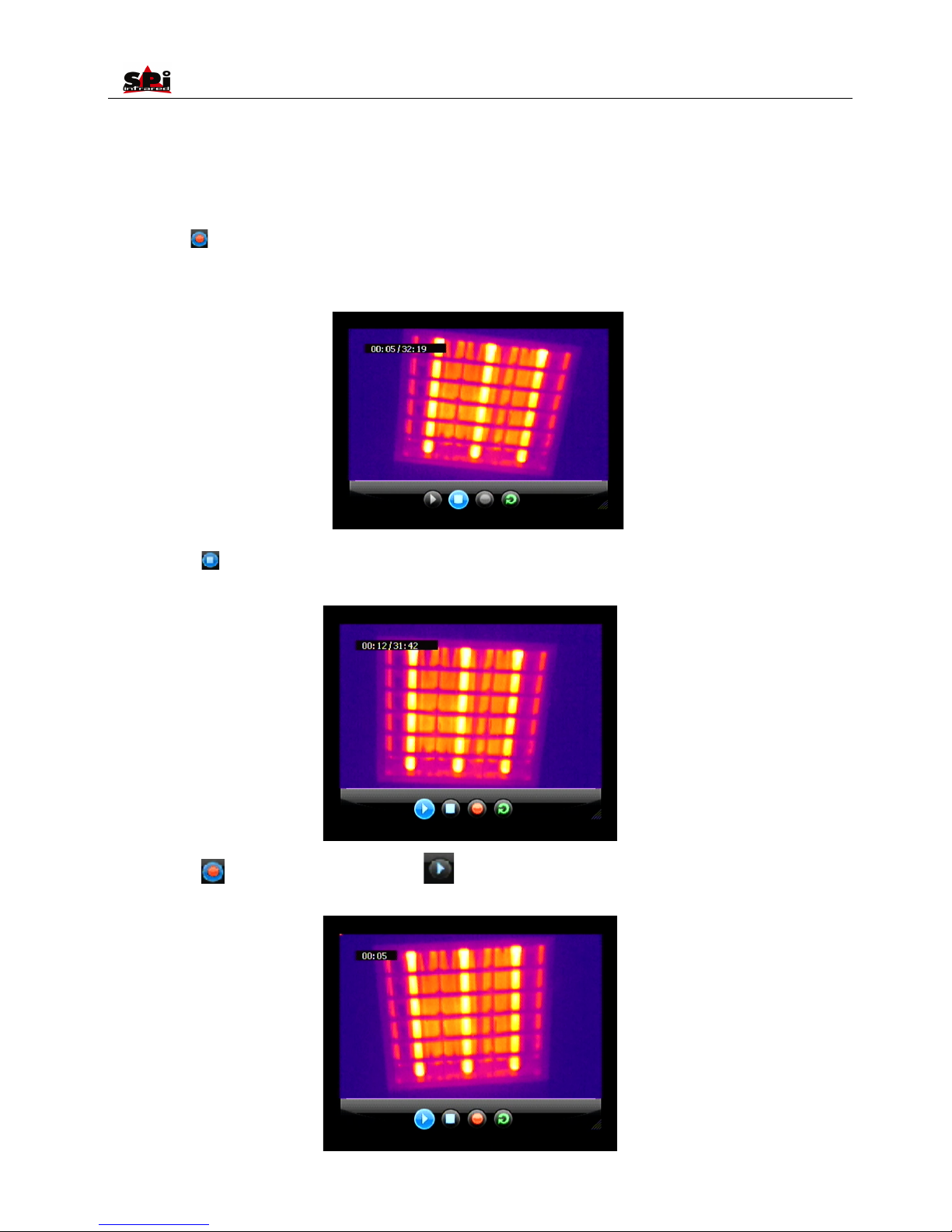
• Before video recording, select the video frequency. First enter the menu “Setup”, press “Up” or “Down” to highlight sub-menu “Setting”, press
button “M” to confirm. The option “Video Freq” is highlighted. Press “Up” or “Down” to change its value as 9hz, 15hz or 20hz.
• Enter submenu, press “Tools”, then click option “Video” with the touch pen or press button “Up” and “Down” to highlight it and then press
“Menu” to select it. Screen as below will appear.
Page 35
User Manual
35
• Press icon , the live video recording will start, a time bar will appear on the top-lef
• corner of the screen. The left one is the current recording time, the right one is the max recording time.
Press icon to stop recording. Such screen will appear. And the video will be saved into the mini SD card automatically, with name
“IRV*****”, but no hint will be displayed on the screen.
Press icon will start recording again, press icon will replay the saved video as shown below. The time on the top-left corner
changes while video is replaying.
Page 36
User Manual
36
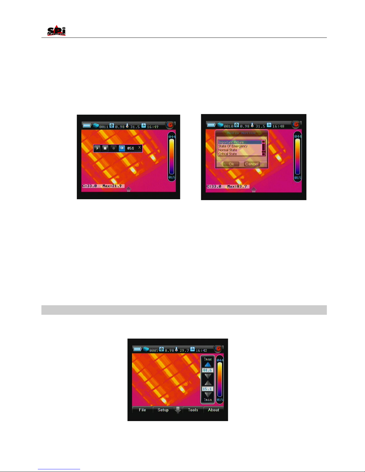
Option Audio
• Voice annotation can be performed on saved or frozen images.
• Click option Audio with the touch pen or press button “Up” and “Down” to highlight it and then press “Menu” to select it. The Voice annotation
tool bar will appear on the screen.
Icon
Significance
Function
Play voice annotation
To replay the recorded voice annotation
Stop recording
To stop voice annotation
Start recording
To start voice annotation
Add text annotation
To add or review text annotation
Voice annotation time
To display the voice annotation time
Exit command
To exit this toolbar
• If voice annotation is required with the image, select the icon Start recording with the touch pen. Or press “OK” to toggle between the icons,
highlight the icon Start recording and then press “Menu” to select it. Now you can start recording annotation and view the time of recording in
the timing box. Meanwhile the icon Stop recording is highlighted.
• Up to 60 seconds of voice clip can be saved for each image. To stop recording at any time, press the icon Stop recording. Once it reaches
60 seconds, recording will stop automatically. At the meantime, icon Play recording is highlighted.
• To replay the recording, select the icon Play recording by clicking it with the touch pen or pressing “Menu” directly. When replaying, the icon
Stop recording is highlighted. You can stop replaying at any time.
• If dissatisfied with the recording, the above operation can be repeated until a satisfactory recording has been made.
• If you are satisfied with the recording and do not want to insert text annotation to the image, you can select the icon Save command to save
it with the image. Then both it and the image will be saved into the memory media, with file name “IR******” displayed in the status bar under
image screen.
Page 37
User Manual
37
• Text annotation can be inserted to a frozen image as well. Select the icon Text Annotation with the touch pen. Or press “OK” to toggle
between the icons, highlight the icon Text annotation and then press “Menu” to select it. Then the annotation dialog box appears in the
image screen. To select one out of the preset annotations, click it with the touch pen or press “Up” and ”Down” to highlight it. Then click icon
OK with touch pen or press “Menu” to save the annotation with the image.
• Select the icon Save command, then the frozen image with voice annotation and text annotation (if any) will be saved into the memory
media, with file name “IR******” displayed in the status bar on image screen.
• Frozen images (with or without annotation) are saved as JPEG files in the memory media. After saving an image, the camera will switch to
live thermal image status.
• To exit the annotation toolbar at any time, select the icon Exit command or press button M. Then the toolbar will disappear. Press button C to
exit the frozen image and return to the live thermal image status.
• If the SD memory card or the built-in flash memory is fully filled with images, the respective prompt “SD full” or “Storage full” will appear in
the status bar under the image screen when you try to store a new image. If failing to save an image, the prompt “Save error” will appear in
the status bar under the image screen.
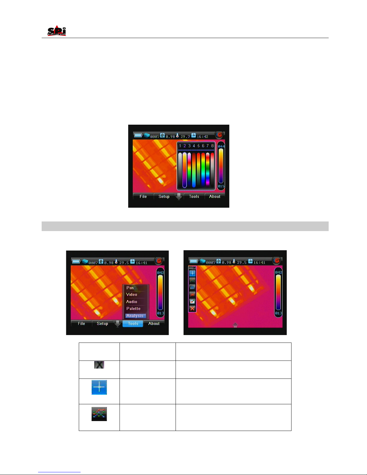
Option Palette
• Click option Palette or the palette bar on the right side of the screen directly with the touch pen or press button “Up” and “Down” to highlight it
and then press “Menu” to select it. The Tmax/Tmin bar will appear on the screen.
• Use touch pen can adjust the value of Tmax/Tmin directly or press button “Up” and “Down” to adjust the value of Tmax and “Left” and “Right”
Page 38
User Manual
38
to adjust the value of Tmin.
• Click the palette bar again with touch pen or press “OK”/“Menu”/”C” can enter into palette adjustment keyboard, then use touch pen to select
applied palette from 8 different palettes or press button “Left” and “Right” to highlight the applied palette and then select by “OK”/”Menu”.
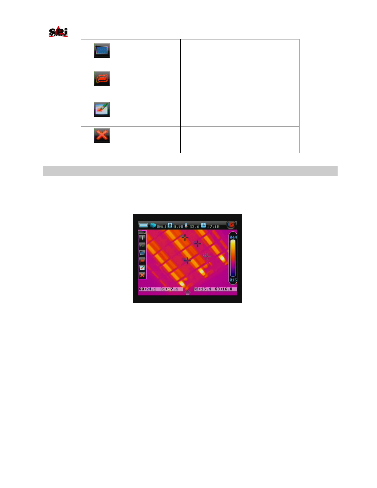
Option Analysis
Click “Analysis” under “Tool” menu by touch pen or press buttons to select it can enter into Analysis menu.
Icon
Significance
Function
Exit command
Exit the analysis toolbar
Spot analysis
Do spot analysis on the replayed image
Line analysis
Do line analysis on the replayed image
Page 39
User Manual
39
Area analysis
Do area analysis on the replayed image
Isotherm analysis
Do isotherm analysis on the replayed image
Discretional area
analysis
Do discretional area analysis on the replayed image
Delete analysis object
Delete selected analysis object or delete analysis
object in the opposite order of the object is added.
Spot Analysis
• Spot Analysis can be performed on live or zoomed or frozen or saved images.
• In live or zoomed images, bring up the main menu, press “Tools” and then select option “Spot” under submenu “Analysis” either by the touch
pen or by pressing the buttons.
• In frozen images, bring up the frozen toolbar with the touch pen or buttons. Click the icon Spot analysis with the touch pen to select it. Or
press “OK” to highlight the icon Spot analysis first and then press “Menu” to select it.
• In saved images, spot analysis can be done when the images are replayed. Bring up the replay toolbar with the touch pen or buttons. Click
the icon Spot analysis with the touch pen to select it; or press “OK” to highlight the icon Spot analysis first and then press “Menu” to select it.
• It is possible to change the spot number from 1 to 4. Click the icon Spot analysis with the touch pen repeatedly can add spot on the screen
with the maximum number limitation as 4; or repeatedly press “OK” and then “Menu” when icon “Spot analysis” is highlighted to add spot on
the screen with the maximum number limitation as 4.
• 4 spots are shown on the screen. Clicking with the touch pen or pressing button “PIC Mode” can toggle between them. Temperature of the
selected spot is displayed in the status bar at the bottom of image screen.
• To move each spot after selecting it, click it with the touch pen, drag it to a desired position and then release it; or press the button “Up”,
“Down”, “Left” or “Right” to a desired position and then release it. The spot temperature shown in the status bar will change accordingly as
the spot moves.
Page 40
User Manual
40
• Press button “C” to exit and return to the live or zoomed or frozen or save image.
Line Analysis
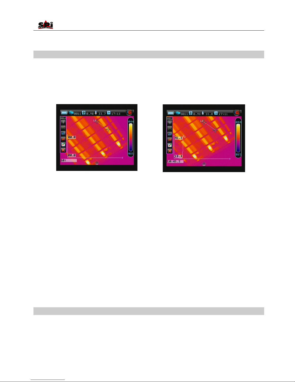
• Line Analysis can be performed on live or zoomed or frozen or saved images. And up to 2 lines can be analyzed simultaneously.
• In live or zoomed images, bring up the main menu, press “Tools” and then select option Line under submenu “Analysis” either by the touch
pen or by pressing the buttons.
• In frozen images, bring up the frozen toolbar with the touch pen or buttons. Click the icon “Line analysis” with the touch pen to select it. Or
press the “OK” to highlight the icon “Line analysis” first and then press “Menu” to select it.
• In saved images, line analysis can be done when the images are replayed. Bring up the replay toolbar with the touch pen or buttons. Click
the icon “Line analysis” with the touch pen to select it; or press the buttons “OK” to highlight the icon “Line analysis” first and then press
“Menu” to select it.
• Then the cursor representing the starting point of the line is displayed in the image.
• At this moment, two methods are available to draw a line. Method 1: Click and drag the cursor to a desired position(i.e. the starting point of
the line) with the touch pen and drag the cursor to another desired position (i.e. the ending point of the line), then release the cursor. A line is
drawn. Method 2: Press the buttons “Up”, “Down”, “Left” or “Right” to move the cursor to a desired position, press “OK” to confirm the
position (i.e. the starting point of the line); press the direction buttons again to another position and then press “OK” to confirm the new
position (i.e. the ending point of the line). Then the line is drawn.
• Press “OK” to confirm the line. At the meantime, the line profile is displayed in the image as well, with the Max and Min temperature of the
line displayed in the coordinate system.
• In live or zoomed images, the line profile and temperatures will change in real time as the image changes.
• Maximum 2 lines can be analyzed simultaneously.
• Press button “C” to exit and return to the live or frozen or save image.
Area Analysis
• Area Analysis can be performed on live or zoomed or frozen or saved images.
• In live or zoomed images, bring up the main menu, press “Tools” and then select option “Area” under submenu “Analysis” either by the touch
pen or by pressing the buttons.
• In frozen images, bring up the frozen toolbar with the touch pen or buttons. Click the icon “Area analysis” with the touch pen to select it. Or
Page 41
User Manual
41
press “OK” to highlight the icon Area analysis first and then press “Menu” to select it.
• In saved images, area analysis can be done when the images are replayed. Bring up the replay toolbar with the touch pen or buttons. Click
the icon “Area analysis” with the touch pen to select it; or press “OK” to highlight the icon Area analysis first and then press “Menu” to select
it.
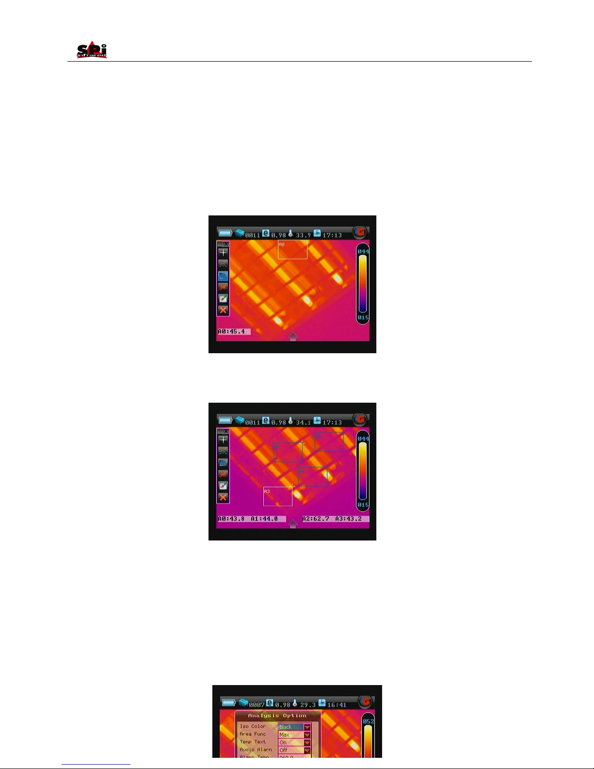
• 4 areas can be displayed on the screen. Clicking with the touch pen or pressing “Pic Mode” can toggle between them. Temperature of the
selected area as well as the temperature measurement type, Minimum, Average or Maximum will be displayed in the status bar under the
image screen.
• To move each area after selecting it, click at its center with the touch pen, move it to a desired position and then release it; or press the
buttons “Up”, “Down”, “Left” or “Right” to a desired position and then release it. The temperature displayed in the status bar will accordingly
change.
• To change the size of an area after selecting it, click at one of its four corners with the touch pen, drag the corner to a desired position and
then release it. Or select the area and press button “OK”, then use “Up”, “Down”, “Left”, and “Right” to adjust the size of area and then
release it.
• Areas can be set to display the Maximum, Average or Minimum temperature. This is done by setting the value of Area Func in option
Analysis under submenu Setup and then choosing button OK to confirm the setup.
Page 42
User Manual
42
• It is possible to change the area number from 1 to 4. Click the icon Area analysis with the touch pen repeatedly can add area on the screen
with the maximum number limitation as 4; or repeatedly press “OK” and then “Menu” when icon “Area analysis” is highlighted to add area on
the screen with the maximum number limitation as 4.
• Press button C to exit and return to the live or frozen or save image.
Isotherm Analysis
• Isotherm Analysis can be performed on live or zoomed or frozen or saved images.
• In live or zoomed images, bring up the main menu, press “Tools” and then select option “Isotherm” under submenu “Analysis” either by the
touch pen or by pressing the buttons.
• In frozen images, bring up the frozen toolbar with the touch pen or buttons. Click the icon “Isotherm analysis” with the touch pen to select it.
Or press “OK” to highlight the icon Isotherm analysis first and then press “Menu” to select it.
• In saved images, isotherm analysis can be done when the images are replayed. Bring up the replay toolbar with the touch pen or buttons.
Click the icon “Isotherm analysis” with the touch pen to select it; or press “OK” to highlight the icon Isotherm analysis first and then press
“Menu” to select it.
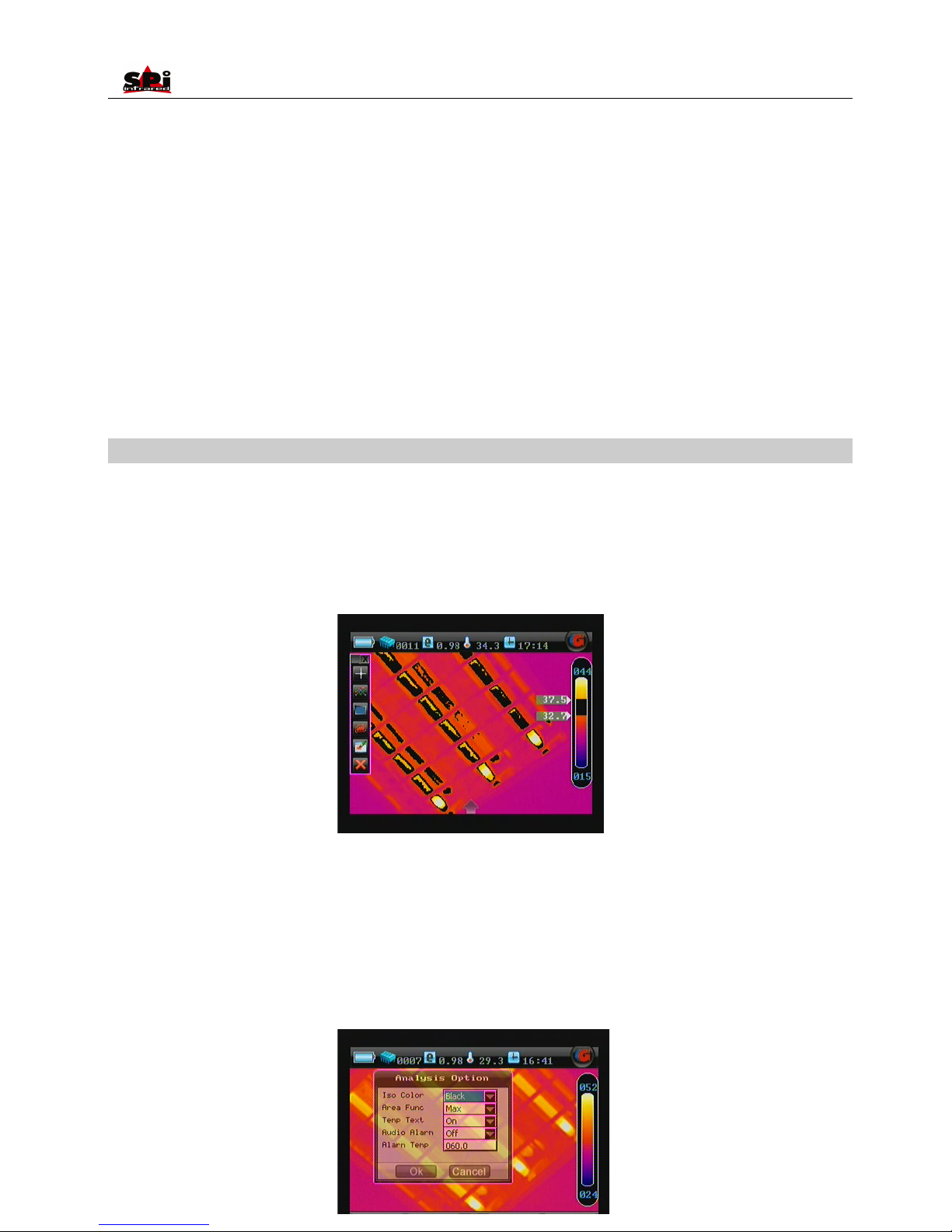
• Move the button “Up” or “Down” to set the maximum temperature of the isotherm band, “Left” or “Right” to set the minimum temperature of
the isotherm band.
• There are three isotherm colors to choose from, black, green and white. This is done by setting the value of sub-option Iso Color in option
Analysis under submenu Setup and then choosing button OK to confirm the setup.
Page 43
User Manual
43
• Press button C to exit and return to the live or frozen or save image.
Discretional area Analysis
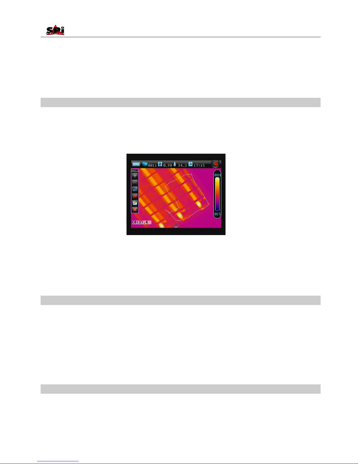
• Discretional area analysis can be performed on live or zoomed or frozen images.
• In live or zoomed images, bring up the main menu, press “Tools” and then select “discretional area analysis” under submenu “Analysis”
either by touch pen or by pressing the buttons.
• User can draw the required analysis area by the touch pen.
• Discretional area can be set to display the Maximum, Average or Minimum temperature. This is done by setting the value of Area Func in
option Analysis under submenu Setup and then choosing button OK to confirm the setup.
• Press button C to exit and return to the live or frozen or save image.
Save
• Save can be performed on live or zoomed or frozen or saved images.
• In live or zoomed images, bring up the main menu, press “Tools” and then select option “Save” under submenu “Analysis” either by the touch
pen or by pressing the buttons.
• In frozen images, bring up the frozen toolbar with the touch pen or buttons. Click the icon “Save” with the touch pen to select it. Or press
“OK” to highlight the icon Save first and then press “Menu” to perform it.
• “Save” can save the analysis objects on certain image.
Delete
• Delete can be performed on live or zoomed or frozen or saved images.
• In live or zoomed images, bring up the main menu, press “Tools” and then select option “Delete” under submenu “Analysis” either by the
touch pen or by pressing the buttons.
Page 44
User Manual
44
• In frozen images, bring up the frozen toolbar with the touch pen or buttons. Click the icon “Delete” with the touch pen to select it. Or press
“OK” to highlight the icon Delete first and then press “M” to perform it.
• “Delete” can cancel the selected analysis objects on certain image.
Histogram Analysis
• Histogram Analysis can be performed on live or zoomed or frozen or saved images.
• In live or zoomed images, bring up the main menu, select option Histogram under submenu Function either by the touch pen or by pressing
the Ok, and then set its value to be ON. Save the setup and back to the live or zoomed image, then histogram of the image will be displayed
at the right bottom corner of the image. To close the histogram, back to the menu and set the option Histogram to be Off.
Menu About
• Click the icon “ ” at the bottom the screen with the touch pen to bring up the main menu and then click the submenu About. Or press the
“Menu” button to bring up the main menu and press “Left” or “Right” button to select the submenu About.
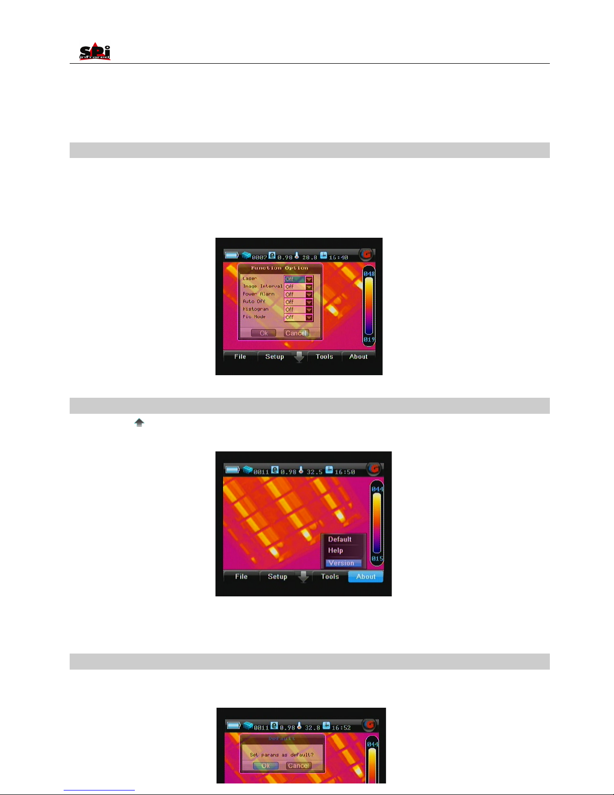
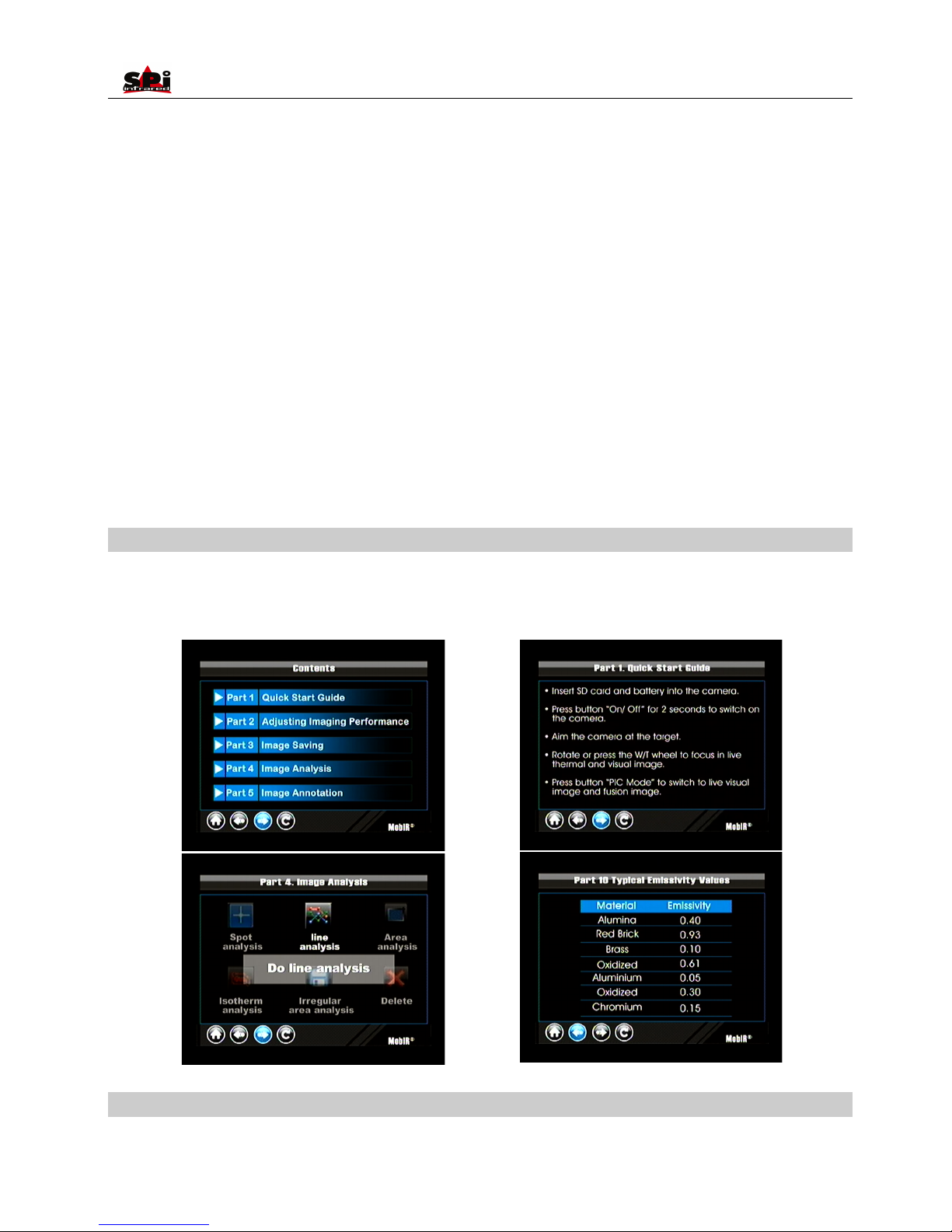
• Three options Default. Help and Version are present in the screen. Clicking them respectively with the touch pen or press “Up” or “Down”
button can toggle between them.
Option Default
• Click option Default under submenu “About” with the touch pen or press “Up” and “Down” to highlight it and press “Menu” to select. Then the
Default dialog box appears on the screen.
Page 45
User Manual
45
• Camera setup parameters and filter range remain the same after re-powering on the camera. But they can be resumed to the factory
configured ones when needed.
• Clicking button Yes or pressing “Menu” will exit the command. Then a NUC is performed automatically. After NUC, all the parameters and
the filter range become the factory configured ones.
• Clicking button No or pressing button C can give up the command.
• To toggle between the buttons Yes and No, press button Ok or press button Left or Right. To select them respectively, click them with the
touch pen or press button M.
Help
• Click option Help under submenu “About” with the touch pen or press “Up” and “Down” to highlight it and press “Menu” to select. Then
images telling you how to operate the camera will appear on the screen.
Here are some examples:
Version
• Click option Version c
Page 46
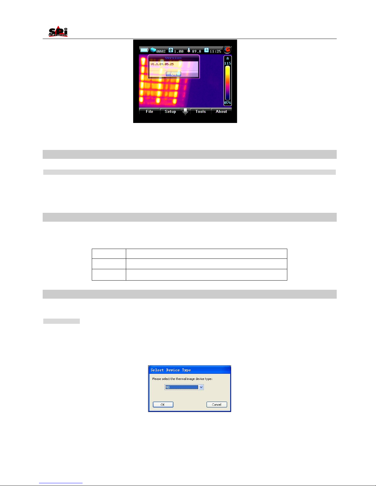
User Manual
46
Infrared Video
General Information
The infrared video with temperature information taken by RAZ-IR® NANO can be transferred to PC via 2GB mini SD card or through USB2.0 for
further analysis by Guide IR software. The Infrared video function is displayed in the computer and controlled by the Guide IR Analyser. Before
the communication please install the USB driver and IR Analyser into your computer.
PC System Requirements
Operating system: Window 2000 or higher (IE5.0 or higher)
Software: Microsoft® Office 2000 or higher
Hardware:
Processor
Pentium 4 2.4G or Above
RAM
At least 512M
Others
Independent Graphic Card
Using commands for infrared video analysis
After connecting the camera of RAZ-IR® NANO to the PC and operate the IR Analyser, you can use the relative commands to do all kinds of
analysis and remote control the RAZ-IR® NANO.
Video Command
Use this command to get infrared video from RAZ-IR® NAN O directly or directory path of the PC where the films are saved
Device Video
Make sure the camera of RAZ-IR® NANO is under normal working status and connect the RAZ-IR® NANO with the PC via USB2.0 to activate
this command; it will bring a dialog box as following
Select M8 and press ok to confirm, the infrared video is open as following
Page 47
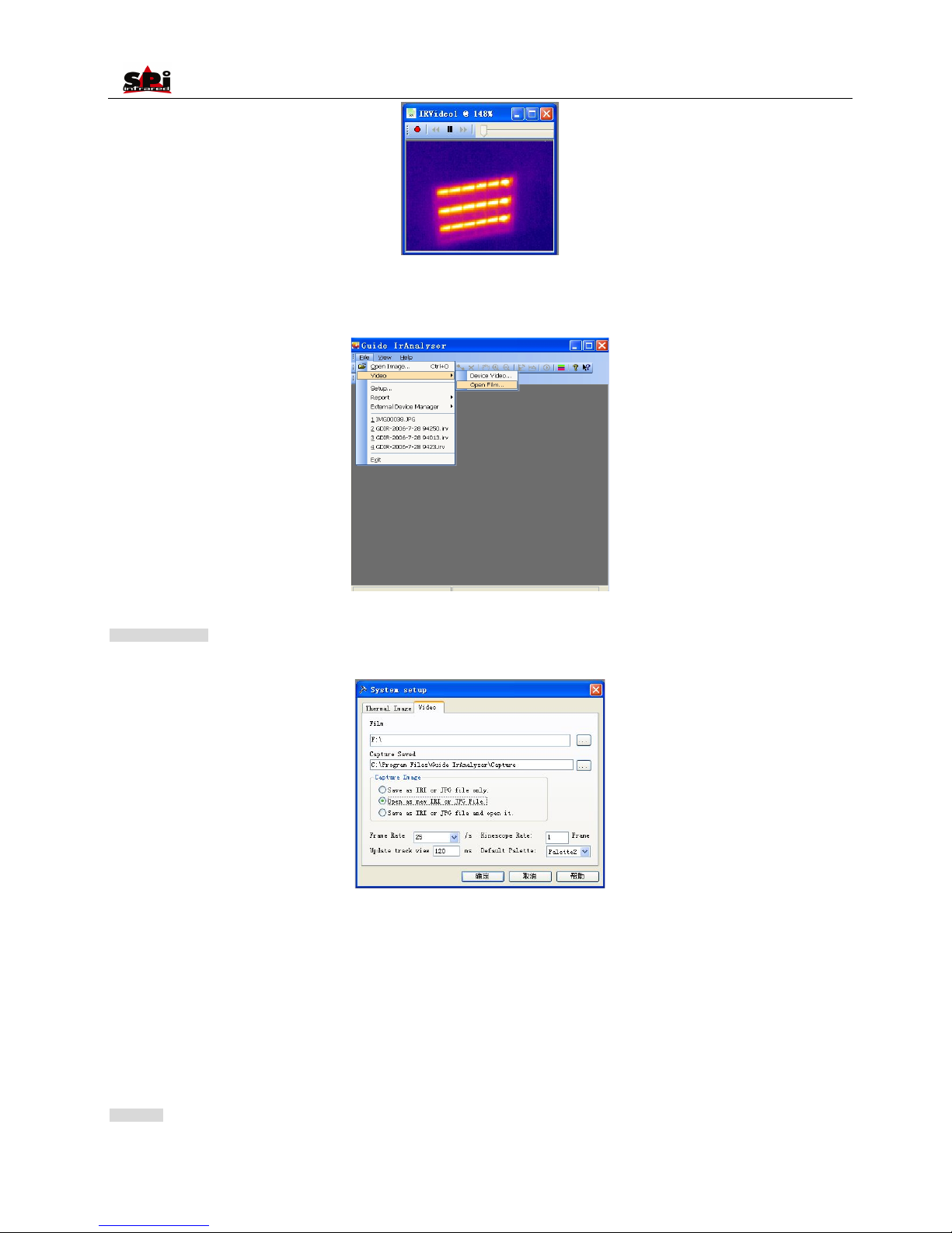
User Manual
47
Open Film
Use this command to open the saved Video file in the directory path of PC. The software will play this file and further analysis can be done on it.
Setup Command
Use this command to set a directory on the hard disks to store the infrared video, capture image and set other relevant information.
Film: set the directory path to save the video recording
Capture Saved: set the directory path to save the captured image
Frame Rate: set the frame of thermal image per second. The default value is 25/ second
Kinescope Rate: set the frame of thermal video. The default value is 1 frame.
Update track view: update the interval between track circles
Default Palette: set the palette to be used for the infrared video
After saving the setup, the program will automatically go to the directory when opening infrared video and perform the track circle
Menu Bar
Menu bar consists of seven sub-menu options, including File, Video, Measure, Tools, View, Window and Help.
Page 48
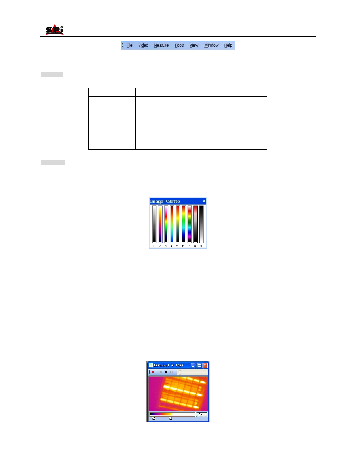
User Manual
48
Keeping left button of the mouse depressed and moving the mouse will allow you to move the menu bar to any desired place.
File Menu
The File menu offers the following commands:
Open Image
Open an existing image file or infrared video
Video
Get infrared video from camera or from the directory path of the
PC where the films are saved
Close
Close an opening image file or infrared video
Setup
Set the directory where to store infrared video and relevant
information
Exit
Exit the Guide IrAnalyser® program
Video Menu
Palette command
Select a palette for the current infrared video. Nine palettes as follows are available.
Auto adjustment command
Use this command to choose adjust image color automatically or manually.
Auto adjustment: the system mapped every image to the appointed pseudo color according to its temperature.
Manual adjustment: mapped the temperature range to the appointed palette via appointing the maximum and minimum temperature, then
the image will be displayed. User can observe the image of appointed temperature range via manual adjustment.
Note:
Manual adjustment is to adjust temperature range. The image will be under manual mode after adjusting the temperature. Execute this
command to return to auto mode.
Gauge Setting Command
The program establishes a mapping function for temperature and brightness of each image file. This command utilizes this mapping function to
adjust brightness of the current opening image file. Dialog box of Temp Range will appear after choosing this command.
Page 49
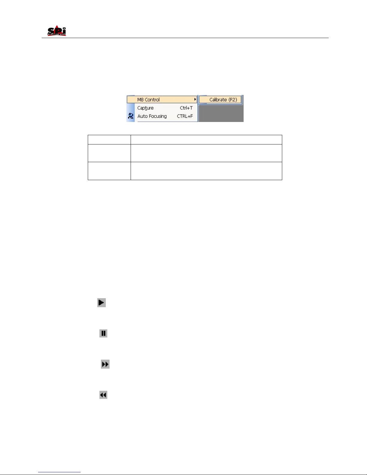
User Manual
49
Moving the scale pointer to select a suitable temperature range. Or click button Auto to restore the original brightness.
Note:
Double clicking the opening image file will activate this command as well.
M8 control command
The following command is available if the camera connected with PC via USB 2.0 is M8.
Calibration (F2)
Send calibration command to the camera
Near Focus (F3)
Press F3 continously to adjust near focus, stop adjusting by releasing the
bottom
Far Focus (F4)
Press F4 continously to adjust far focus, stop adjusting by releasing the
bottom
Video capture command
When playing infrared video, use this command under Video Menu or Press Ctrl + T to capture the current image. The capture image can be
done as following
Save as .IRI file or .JPG file to the appointed directory path
Open as new .IRI or .JPG file
Save as .IRI file or .JPG file and open it
Note: For M8, the file fomat is .JPG
Auto focusing command
When playing infrared video, use this command under Video Menu or Press Ctrl + F to perform auto fucus operation on camera.
Play command
Use this command or press to play infrared video. If it is play mode, perform this command to change it to pause mode.
Pause Command
Use this command or press to pause infrared video. If it is pause mode, perform this command to change it to play mode
Forward command
User this command or press to make the video go forward by one frame when playing video.
Backward command
Use this command or press to make the video go backward by one frame when playing video.
Record command
Page 50

User Manual
50
Use this command or press to record the video capture by TP8 and save it in appointed directory. The default saving directory is in the
sub-directory of capture under installation directory. Computer system will denominate the video file automatically.
Perform this command again after stopping record.
Video Output
• Composite video output (PAL or NTSC mode) option is available in RAZ-IR® NANO camera. With this option you can view the live image
captured by the camera on a monitor or a recording device.
Before trying to use this option, ensure that the RAZ-IR® NA NO camera is switched off.
• Properly connect the camera to the monitor (or recording device) with the video cable supplied together with the camera..
• Power on the monitor.
• Power on the camera.
• Enter the submenu System under menu Setup, choose option VideoOut and set its value to be “PAL” or “NTSC”.
• Press button Ok to save the setup and return to the live image.
• When viewing the live image, you can still use the bottons to control the camera.
• After viewing the live image, power off the camera, monitor (or recording device) and disconnect the cable.
Note:
• It is required to power off the camera before connecting it to a monitor or a recording device.
Transferring Data from the Camera to PC
• Before transferring data from the RAZ-IR® NANO camera to PC, ensure that the PC offers USB2.0 interface and the USB driver for
the camera has been successfully installed in the PC.
• Power on the camera, enter menu “Setup”, select sub-menu “System”, press button ‘OK” to highlight the option “Storage”, then select the
storage medium. Or click the storage medium icon in the information bar to change the storage medium.
• Connect the camera to PC through the USB extension cable.
• If the storage medium is set as “UFLASH”, no hint will display on either the PC or the M8 screen. Image export, image analysis, live video
recording etc. can be done in the PC. Images saved in UFLASH can be transferred to PC via IrAnalyser.
• If the storage medium is set as “SD card”, the PC will identify the M8 as a removable hard disk, and also a hint “USB Mode” will display on
the M8 screen, you can copy the saved data to PC or delete them from the card, or even format the SD card and etc. But you cannot operate
on it in the Guide IrAnalyser® software.
Note: To format the SD card, choose FAT32 as the file system. It is recommended to create a new folder in your PC to save the
transferred data.
• For more information, pls refer to the user manual of Guide IrAnalyser® software.
Installing the Camera USB Driver to PC
Before installing the USB driver, ensure the camera storage medium is set as “UFLASH”, both camera and your PC are working and your PC
offers at least one USB2.0 port.
• When there is no menu in the live thermal image, properly connect the USB interfaces of the camera to a USB2.0 port of your PC with the
Page 51
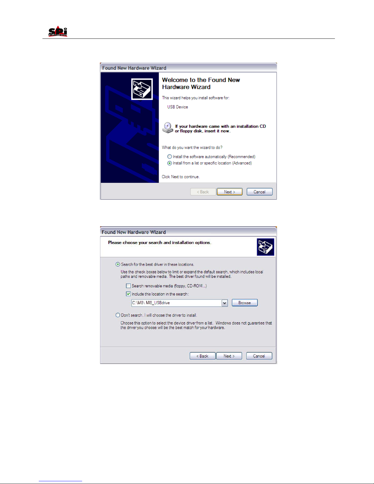
User Manual
51
USB extension cable.
• Microsoft® Windows launches a Found New Device Wizard to guide you to install the driver as follows:
• Choose “Install from a list or specific location (advanced)” and include the folder where you save the driver program. Then Click button Next
to go further.
• Installation starts. When getting to the step as shown below, choose “Continue anyway” to proceed further.
Page 52
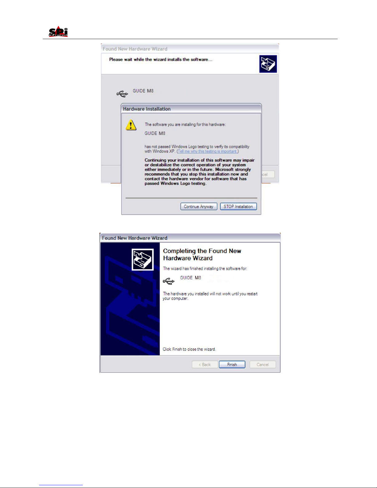
User Manual
52
• Installation continues and finishes quickly. Click button Finish.
• Go to Device Manager to check and confirm whether the driver has been successfully installed. If there is “GUIDE M8 After Renumeration
(guideusbd0.sys)” listed under Universal Serial Bus Controller, it indicates the driver has been properly installed and you can transfer data
from the camera to PC now.
• The procedures to go to Device Manager is as follows: Clicking My Computer-> Clicking the right mouse and choosing Property-> Choosing
menu Hardware in the System Property dialog box-> Choosing option Device Manager under the menu Hardware.
Page 53
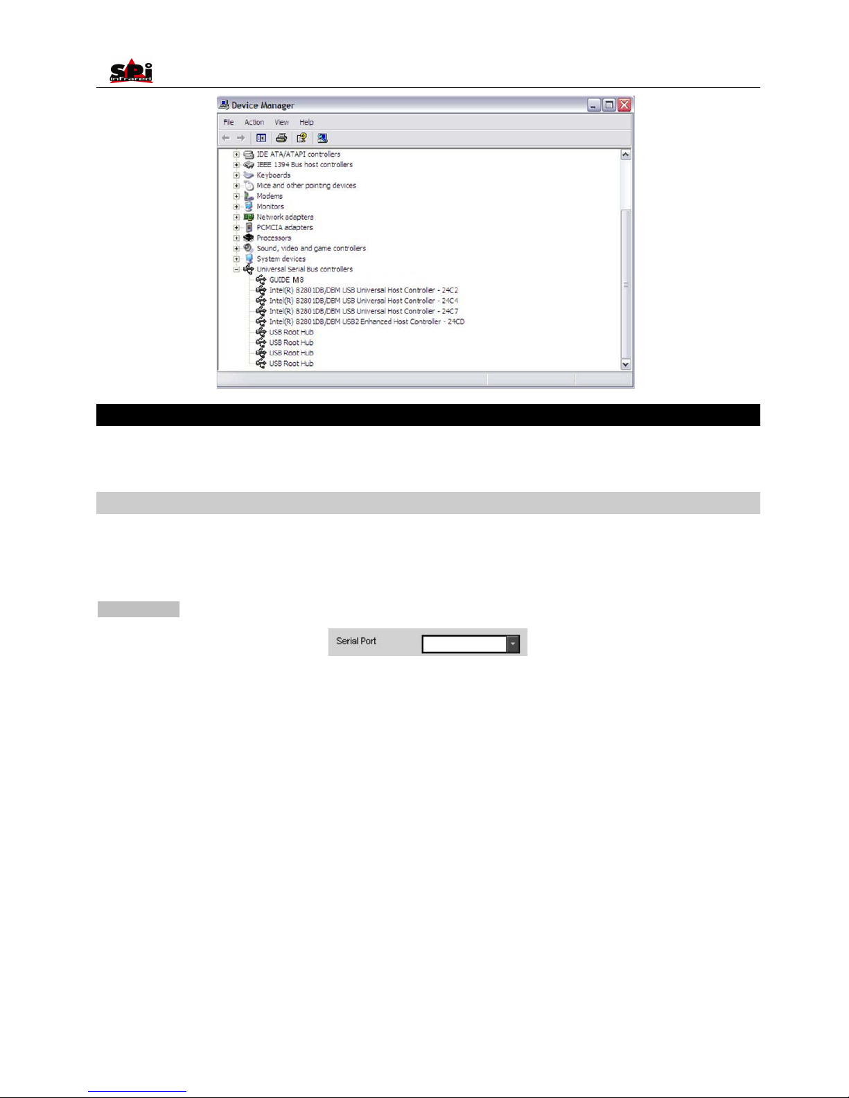
User Manual
53
Controlling the Camera through RS232 Communication Protocol
RS232 communication protocol is offered with the RAZ-IR® NANO camera. Through the protocol the camera can be conveniently controlled on
PC at a remote monitoring place.
Using the protocol
Before using the protocol, please ensure the camera and your PC have been properly connected by the RS232/ video cable offered
together with the camera. Click on the file “M8RS232.exe” to run the protocol.
There is only one control interface of the protocol as shown below:
Parts described:
There are 9 COM interfaces available for RS232 communication.
Page 54
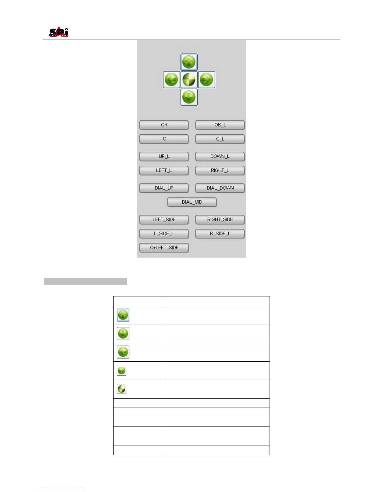
User Manual
54
Buttons for operating the camera.
Using the buttons in different modes:
In real-time mode:
Button
Function
Adjust the values of Tmin and Tmax
Zoom in/out
Bring out the information bar
Bring out the analysis bar
Bring out the main menu
OK
Freeze/save a live thermal image
OK_L
Idle
C
Idle
C_L
Calibration with shutter
UP_L
Idle
DOWN_L
Idle
Page 55
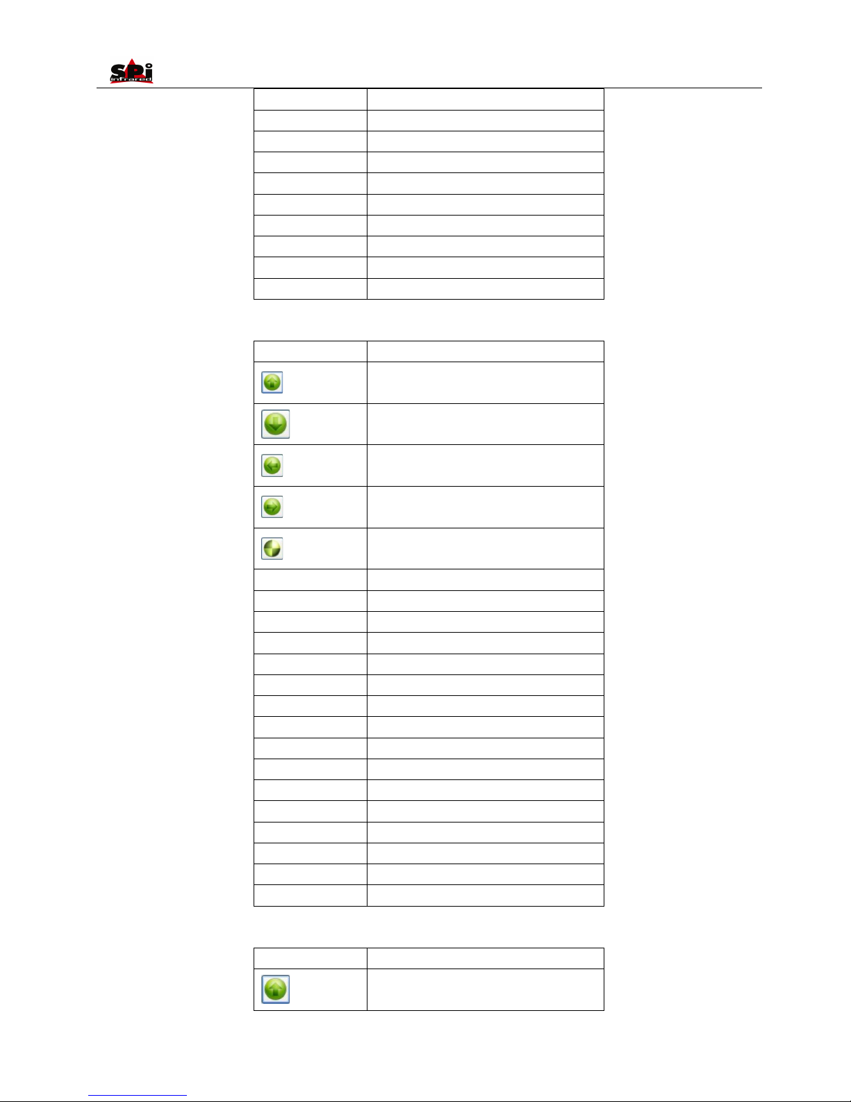
User Manual
55
LEFT_L
Idle
RIGHT_L
Idle
DIAL_UP
Far focus
DIAL_DOWN
Near focus
DIAL_MID
Auto focus
LEFT_SIDE
Switch between thermal/visual/IR fusion modes
RIGHT_SIDE
Bring out Option Target dialog box
L_SIDE_L
Switch between Auto/Manual modes
R_SIDE_L
Switch on laser locator
C+LEFT_SIDE
Calibration without shutter
In frozen mode:
Button
Function
Move the cursor upwards
Move the cursor downwards
Move the cursor leftwards
Move the cursor rightwards
Bring out the main menu
OK
Save the frozen thermal image
OK_L
Idle
C
Idle
C_L
Exit the frozen mode
UP_L
Move the cursor upwards(Accelerated)
DOWN_L
Move the cursor downwards(Accelerated)
LEFT_L
Move the cursor leftwards(Accelerated)
RIGHT_L
Move the cursor rightwards(Accelerated)
DIAL_UP
Idle
DIAL_DOWN
Idle
DIAL_MID
Idle
LEFT_SIDE
Switch between thermal/visual/IR fusion modes
RIGHT_SIDE
Bring out Option Target dialog box
L_SIDE_L
Switch between Auto/Manual modes
R_SIDE_L
Switch on laser locator
C+LEFT_SIDE
Idle
In analysis selection mode:
Button
Function
Idle
Page 56
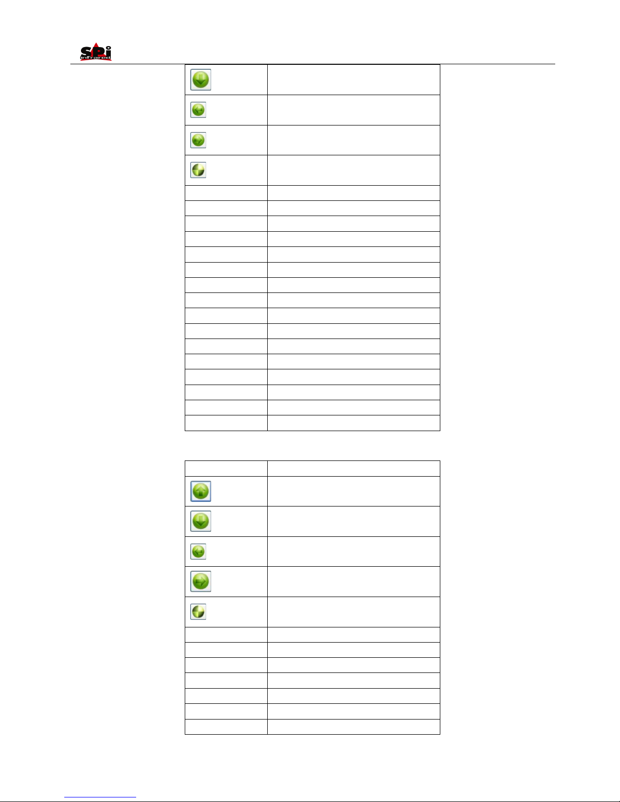
User Manual
56
Idle
Idle
Idle
Enter into different analysis mode
OK
Switch between different analysis modes
OK_L
Freeze or save image
C
Exit analysis dialog box
C_L
Exit the frozen mode/make compensation
UP_L
Idle
DOWN_L
Idle
LEFT_L
Idle
RIGHT_L
Idle
DIAL_UP
Far focus
DIAL_DOWN
Near focus
DIAL_MID
Auto focus
LEFT_SIDE
Idle
RIGHT_SIDE
Idle
L_SIDE_L
Idle
R_SIDE_L
Idle
C+LEFT_SIDE
Idle
In spot analysis mode:
Button
Function
Move the cursor upwards
Move the cursor downwards
Move the cursor leftwards
Move the cursor rightwards
Bring out the main menu
OK
Idle
OK_L
Freeze/save the thermal image
C
Return back to analysis selection bar
C_L
Exit the frozen mode/make compensation
UP_L
Move the cursor upwards(Accelerated)
DOWN_L
Move the cursor downwards(Accelerated)
LEFT_L
Move the cursor leftwards(Accelerated)
Page 57
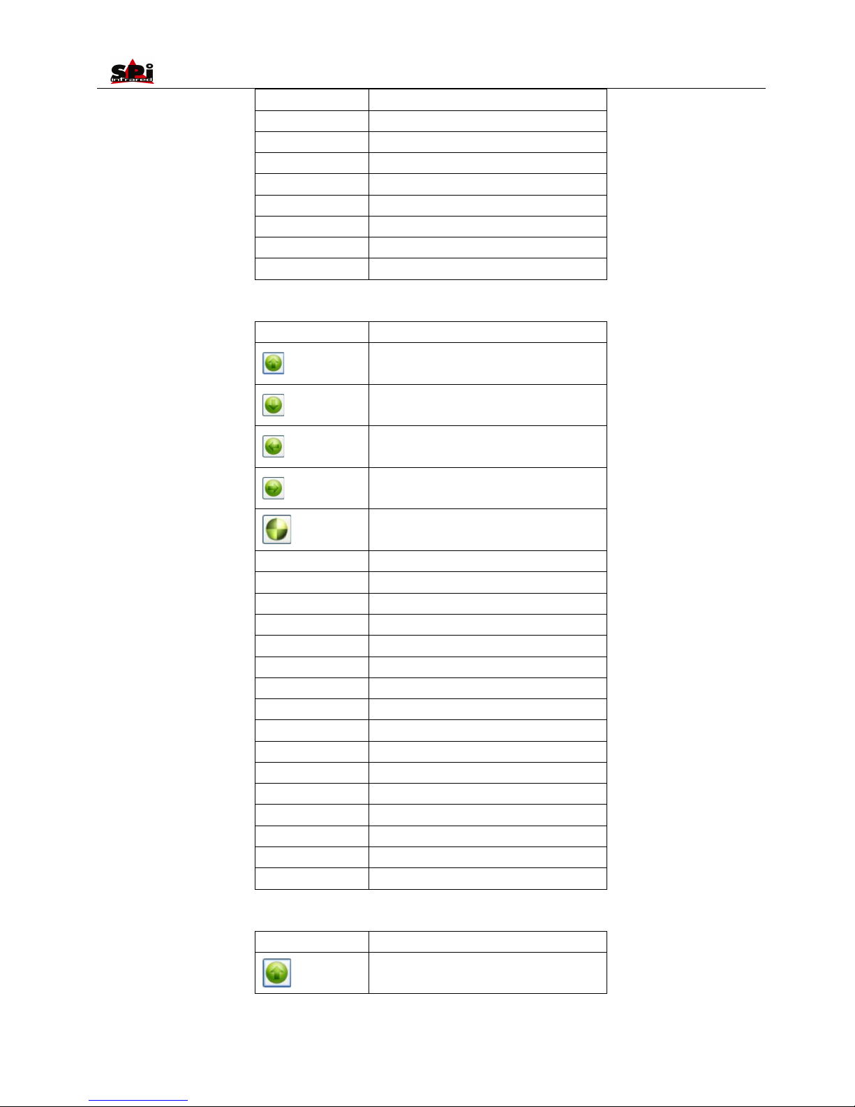
User Manual
57
RIGHT_L
Move the cursor rightwards(Accelerated)
DIAL_UP
Far focus
DIAL_DOWN
Near focus
DIAL_MID
Auto focus
LEFT_SIDE
Switch between different spots
RIGHT_SIDE
Bring out Option Target dialog box
L_SIDE_L
Switch between Auto/Manual modes
R_SIDE_L
Switch on laser locator
C+LEFT_SIDE
Idle
In line analysis mode:
Button
Function
Move the cursor upwards
Move the cursor downwards
Move the cursor leftwards
Move the cursor rightwards
Bring out the main menu
OK
Confirm the location of one spot of the line
OK_L
Freeze/save the thermal image
C
Return back to analysis selection bar
C_L
Exit the frozen mode/make compensation
UP_L
Move the cursor upwards(Accelerated)
DOWN_L
Move the cursor downwards(Accelerated)
LEFT_L
Move the cursor leftwards(Accelerated)
RIGHT_L
Move the cursor rightwards(Accelerated)
DIAL_UP
Far focus
DIAL_DOWN
Near focus
DIAL_MID
Auto focus
LEFT_SIDE
Switch between different lines
RIGHT_SIDE
Bring out Option Target dialog box
L_SIDE_L
Switch between Auto/Manual modes
R_SIDE_L
Switch on laser locator
C+LEFT_SIDE
Idle
In area analysis mode:
Button
Function
Move the area upwards/enlarge or reduce the
area
Page 58
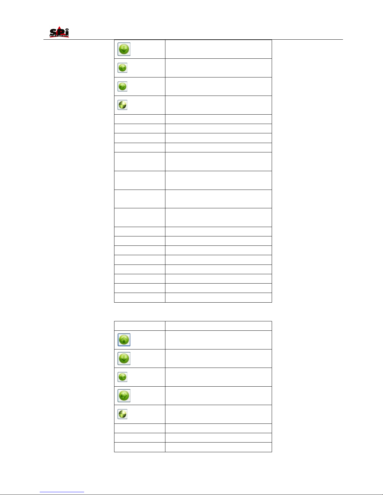
User Manual
58
Move the area downwards/enlarge or reduce
the area
Move the area leftwards/enlarge or reduce the
area
Move the area rightwards/enlarge or reduce the
area
Bring out the main menu
OK
Confirm the location of the area
OK_L
Freeze/save the thermal image
C
Return back to analysis selection bar
C_L
Exit the frozen mode/make compensation
UP_L
Move the area upwards/enlarge or reduce the
area (Accelerated)
DOWN_L
Move the area downwards/enlarge or reduce
the area (Accelerated)
LEFT_L
Move the area leftwards/enlarge or reduce the
area (Accelerated)
RIGHT_L
Move the area rightwards/enlarge or reduce the
area (Accelerated)
DIAL_UP
Far focus
DIAL_DOWN
Near focus
DIAL_MID
Auto focus
LEFT_SIDE
Switch between different areas
RIGHT_SIDE
Bring out Option Target dialog box
L_SIDE_L
Switch between Auto/Manual modes
R_SIDE_L
Switch on laser locator
C+LEFT_SIDE
Idle
In discretional area analysis mode:
Button
Function
Idle
Idle
Idle
Idle
Bring out the main menu
OK
Idle
OK_L
Freeze/save the thermal image
C
Return back to analysis selection bar
Page 59
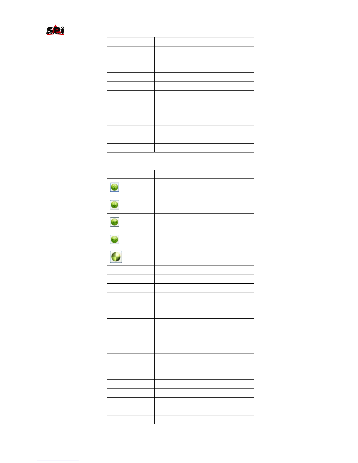
User Manual
59
C_L
Exit the frozen mode/make compensation
UP_L
Idle
DOWN_L
Idle
LEFT_L
Idle
RIGHT_L
Idle
DIAL_UP
Far focus
DIAL_DOWN
Near focus
DIAL_MID
Auto focus
LEFT_SIDE
Idle
RIGHT_SIDE
Bring out Option Target dialog box
L_SIDE_L
Switch between Auto/Manual modes
R_SIDE_L
Switch on laser locator
C+LEFT_SIDE
Idle
In isotherm area analysis mode:
Button
Function
Move the threshold of high temperature
upwards
Move the threshold of high temperature
downwards
Move the threshold of low temperature
downwards
Move the threshold of low temperature upwards
Bring out the main menu
OK
Idle
OK_L
Freeze/save the thermal image
C
Return back to analysis selection bar
C_L
Exit the frozen mode/make compensation
UP_L
Move the threshold of high temperature
upwards (Accelerated)
DOWN_L
Move the threshold of high temperature
downwards (Accelerated)
LEFT_L
Move the threshold of low temperature
downwards (Accelerated)
RIGHT_L
Move the threshold of low temperature upwards
(Accelerated)
DIAL_UP
Far focus
DIAL_DOWN
Near focus
DIAL_MID
Auto focus
LEFT_SIDE
Idle
RIGHT_SIDE
Bring out Option Target dialog box
L_SIDE_L
Idle
Page 60
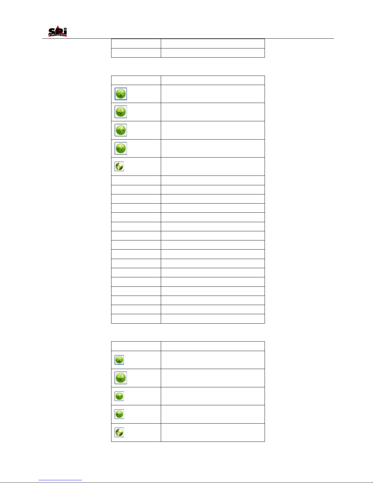
User Manual
60
R_SIDE_L
Switch on laser locator
C+LEFT_SIDE
Idle
In image/video list mode:
Button
Function
Select image upwards
Move image downwards
Move image leftwards
Move image rightwards
Confirm the selection
OK
Toggle between different selection buttons
OK_L
Idle
C
Return back to image list mode
C_L
Idle
UP_L
Idle
DOWN_L
Idle
LEFT_L
Idle
RIGHT_L
Idle
DIAL_UP
Idle
DIAL_DOWN
Idle
DIAL_MID
Idle
LEFT_SIDE
Idle
RIGHT_SIDE
Idle
L_SIDE_L
Idle
R_SIDE_L
Idle
C+LEFT_SIDE
Idle
In image/video replay mode:
Button
Function
Move the central cursor upwards
Move the central cursor downwards
Move the central cursor leftwards
Move the central cursor rightwards
Bring out the main menu
Page 61
User Manual
61
OK
Idle
OK_L
Idle
C
Return back to image/video list mode
C_L
Idle
UP_L
Move the central cursor upwards (Accelerated)
DOWN_L
Move the central cursor downwards
(Accelerated)
LEFT_L
Move the central cursor leftwards (Accelerated)
RIGHT_L
Move the central cursor rightwards
(Accelerated)
DIAL_UP
Idle
DIAL_DOWN
Idle
DIAL_MID
Idle
LEFT_SIDE
Switch between thermal/visual/IR fusion modes
RIGHT_SIDE
Idle
L_SIDE_L
Adjust Tmin/Tmax value
R_SIDE_L
Idle
C+LEFT_SIDE
Idle
In touch pen adjusting mode:
Button
Function
Idle
Idle
Idle
Idle
Confirm
OK
Toggle between different buttons
OK_L
Idle
C
Exit touch pen adjusting mode
C_L
Idle
UP_L
Idle
DOWN_L
Idle
LEFT_L
Idle
RIGHT_L
Idle
DIAL_UP
Idle
DIAL_DOWN
Idle
DIAL_MID
Idle
LEFT_SIDE
Idle
RIGHT_SIDE
Idle
Page 62
User Manual
62
L_SIDE_L
Idle
R_SIDE_L
Idle
C+LEFT_SIDE
Idle
In voice recording mode:
Button
Function
Idle
Idle
Idle
Idle
Confirm
OK
Toggle between different buttons
OK_L
Idle
C
Exit voice recording mode
C_L
Idle
UP_L
Idle
DOWN_L
Idle
LEFT_L
Idle
RIGHT_L
Idle
DIAL_UP
Idle
DIAL_DOWN
Idle
DIAL_MID
Idle
LEFT_SIDE
Idle
RIGHT_SIDE
Idle
L_SIDE_L
Idle
R_SIDE_L
Idle
C+LEFT_SIDE
Idle
In parameter value adjusting mode:
Button
Function
Increase the selected value
Decrease the selected value
Select current value leftwards
Select current value rightwards
Page 63
User Manual
63
Confirm
OK
Toggle between different buttons
OK_L
Idle
C
Exit parameter value adjusting dialog box
C_L
Idle
UP_L
Idle
DOWN_L
Idle
LEFT_L
Idle
RIGHT_L
Idle
DIAL_UP
Idle
DIAL_DOWN
Idle
DIAL_MID
Idle
LEFT_SIDE
Idle
RIGHT_SIDE
Idle
L_SIDE_L
Idle
R_SIDE_L
Idle
C+LEFT_SIDE
Idle
Page 64
User Manual
Troubleshooting
The camera does not turn on
Battery improperly installed (i..e battery is not locked in place). Remove battery and install correctly.
Battery contacts are dirty. Clean battery contacts.
Battery charge is low. Recharge battery or replace with fully charged item.
Battery performance is poor
Battery may be defective. Replace battery.
Image is blurry
The target is not in focus. Adjust focus.
Brightness and contrast are inappropriate. Adjust Tmin and Tmax.
Visual image is blurry
The target is not in focus. Adjust focus of the visual camera.
Image contrast is low or there is
no image
Temperature set points Tmin and Tmax are inappropriate. Change the lower set point and upper set point
to values that are more consistent with target temperatures.
Emissivity setting is incorrect. This affects the temperature range set points. Check and amend the
emissivity setting.
The lens cap is on. Remove lens cap.
Condensation on camera lens. Place camera in a dry area at room temperature until condensation
evaporates.
Non-uniformity appears in the image. Perform a non-uniformity calibration.
Temperature measurement is
inaccurate
Emissivity setting is incorrect. Check and amend the emissivity setting.
Temperature set points are inappropriate for this temperature measurement. Select Tmin and Tmax
settings that are closer to the target temperature being measured.
The target is not in focus. Adjust focus.
Condensation on camera lens. Place camera in a dry area at room temperature until condensation
evaporates.
Non-uniformity is severe. Press non-uniformity calibration.
SD card cannot be found
on PC
Change storage medium in camera as “SD card”, then connect to PC, the PC will identify the M8 as a
removable hard disk, and also a hint “USB Mode” will display on the M8 screen. Plz refer to page 50
Camera cannot be found
on PC
Ensure USB driver is successfully installed on the PC.
Change storage medium in camera as “UFLASH” or eject the SD card, then connect to PC, camera can
be controlled in RS232 or IrAnalyser. Plz refer to page 50
Image and video cannot be
read and transferred to PC
in USB mode
Plz check whether the PC has been poisoned first. Usually this is the reason. So plz perform virus-killing
first. And ensure no virus in PC before connecting camera to it.
Emissivity
What Is Emissivity?
The standard of radiation is "blackbody" radiation which exists in any enclosure whose walls are at a uniform temperature. The shape of the
enclosure and the wall material have no effect on this radiation, it being a function of temperature alone.
Page 65

User Manual
65
A small hole in such an enclosure only affects this radiation level very slightly. The area of the hole should not exceed 5% of the area of the walls
of the enclosure, when the radiation passing through the hole is within about one part in a thousand of the blackbody radiation level defined by
the wall temperature. Such a device is fairly easy to build and forms the source on which all thermometers are calibrated.
A surface always emits less radiation than would a black body at the same temperature by a factor called the "emissivity" of the surface.
Emissivity = Radiation emitted by surface
Radiation emitted by black body
How Do We Deal With Emissivity?
If we ignore the emissivity altogether and infer a temperature from the thermometer output, we shall get a temperature lower than the true
temperature by an amount depending on the value of emissivity and the characteristics of the thermometer. This temperature is known as the
"apparent" or "brightness" temperature of the surface. If the emissivity is constant, this temperature rises and falls in exactly the same way as
the true temperature and this may be sufficient for some purposes.
More often the true surface temperature is required. We have:
Actual output = E x output when viewing blackbody
To obtain the true surface temperature we must divide the actual output by the emissivity value E before we convert to temperature.
This is done by setting the emissivity control to the appropriate value.
It is therefore necessary to know the value of the emissivity. There is a vast amount of data available, unfortunately much of it is confusing
because substantially different values are quoted. This is because emissivity depends upon:
a) The basic material
b) Surface condition - roughness and oxidation
c) Temperature
d) Angle of view
e) Wavelength
For materials with smooth, clean (unoxidised) surfaces, emissivities are usually in the range 0.05 to 0.50 and are usually very wavelength
dependent, being higher at shorter wavelengths. The appropriate settings for the RAZ-IR® NANO Thermal Cameras are given in the following
tables. It must be remembered that these are only guideline figures. They can be substantially increased if the surface is rough or even slightly
oxidised.
The values quoted for oxidised metals assume that the metal is heavily oxidised. Thin oxide layers will give an emissivity value between this and
the value for an unoxidised surface.
Page 66

User Manual
66
If a more precise emissivity value is needed or more information is required on how to obtain the emissivity value of a specific material, please
contact: us.
Typical Emissivity Values
Refractories Miscellaneous
Alumina 0.40 Asphalt 0.90
Red Brick 0.93 Carbon >0.90
Graphite 0.85
Alloys Soot 0.95
Brass 0.10 Cement & Concrete 0.90
Oxidized 0.61 Cloth 0.85
Metals
Aluminium 0.05
Oxidized 0.30
Chromium 0.15
Cobalt 0.18
Gold 0.02
Iron & Steel 0.18
Oxidized 0.85
Lead 0.16
Oxidized 0.63
Magnesium 0.12
Nickel 0.15
Platinum 0.10
Silver 0.03
Tin 0.09
Titanium 0.30
Tungsten 0.13
Zinc 0.05
Oxidized 0.11
 Loading...