

Page 1
No.:PS##-OMF0010-C
Technical Specification
Digital Pressure Switch
ISE30-# Series
ZSE30-# Series
Page 2

Contents
Safety
Model Indication Method
Specification
Full View with Dimensions
Names and Functions of Individual Parts
Installation
Examples of Internal Circuit and Wiring
Setting
………………………………………………………P2
………………………………………………………P7
………………………………………………………P8
………………………………………………………P9
………………………………………………………P12
………………………………………………………P13
………………………………………………………P15
………………………………………………………P17
Pressure Setting
Other Functions
Attached Table
………………………………………………………P19
………………………………………………………P21
………………………………………………………P22
-1-
PS##-OMF0010-C
Page 3
Safety
The Digital Press ure Switch and th is technical spe cification essential inf ormation f or the protect ion
of users and others from possible injury and damage to property and to ensure correct handling.
Please check that you fully understand the definition of the following messages (signs) before
going on to read the text, and always follow the instructions.
Also read carefully the technical specification of relevant equipment or apparatus before use.
Indications
IMPORTANT MESSAGES
Read this manual and follow its instructions. Signal words such as WARNING, CAUTION
and NOTE, will be followe d by important s afety inf ormation that mu st be caref ully reviewe d.
Indicates a pote ntially hazard ous situation which could r e su lt in death
or serious injury if you do not follow inst ructio ns.
Indicates a p otentially hazardous situation which if not a voided, may
result in minor injury or moderate injury.
NOTE
Gives you helpful information.
Usage Restrictions
♦This product is designed for use in general equipment for factory automation. Never use this
product with equipment or apparatus that directly concerns human lives*
malfunction or failure can cause a huge loss.
*1: Equipment or apparatus that directly matters human lives means the following:
• Medical equipment such as life support systems or equipment used in operating rooms
• Compulsory equipment required b y law such as the Fire Pre vention Law, Construction Law
and etc.
• Equipment or apparatus that conforms with those mentioned above.
♦Contact our sales department when plans are made f or the product to be used for the system*
including equipment that concerns itself with the safety of persons or that seriously affects the
public. This usage needs special consideration*
*2: The system including equipment that concerns itself with the safety of persons or that seriously
affects the public means the following:
• Nuclear reactor control systems in nuclear power plants, safety protection systems or other
systems important for safety in nuclear power facilities
• Driving control systems of mass transportation systems, and flight control systems
• Equipment or apparatus that comes into contact with foods or beverages
*3: Special consideration means discussing usage with our engineers to establish a safe system
designed as fool-proof, fail-safe, redundant and etc.
3
.
1
, or which
2
♦Special consideration of safety or maintainability should be taken to prevent hazard or loss
caused by a failure or malfunction that is likely to occur in certain probability due to
environmental stress (deterioration).
The special consideration means to fully review the equipment or apparatus in design stage
and to establish a backup system in advance such as a redundant system or fail-safe system.
♦Use for an interlocking circuit
When using the pressure switch as a sensor for interlock, adopt a double interlocking method
such as equipping the mechanical protection function in order to deal with a pressure switch
failure.
Check the pressure switch regularly to ensure proper operation.
-2-
PS##-OMF0010-C
Page 4
Operator
♦This technical specification has been written for those who have knowledge of machinery and
apparatus that use pneumatic equipment and have full knowledge of assembly, operation and
maintenance of such equipment.
♦Please read this technical specification carefully and understand it before assembling, operating
or providing maintenance to the pressure switch.
Safety
♦Do not disassemble, mod ify (including chang e of printed circ uit board) or repa i r.
An injury or failure can result.
♦Do not operate the pressure switch beyond specification range.
Do not use the pressure switch for inflammable or harmful gas or fluid.
Operation at a range that exceeds the specifications can cause a fire, malfunction, or damage to
the pressure switch.
Verify the specifications before use.
♦Do not use the pressure switch in an atmosphere containing combustible or explosive gas.
A fire or explosion can result.
This pressure switch is not an explosion-proof type.
♦These instructions must be followed when using the pressure switch in an interlocking circuit:
• Provide double interlocking by another system such as mechanical protection.
• Check the pressure switch regularly to ensure proper operation.
Otherwise malfunction can cause an accident.
♦These instructions must be followed while in maintenance:
• Turn off the power supply.
• Stop the supplied air, exhaust the residual pressure and verify the release of air before
performing maintenance.
Otherwise it can cause injury.
♦Don’t use this product near by a place where static electricity is a problem.
Otherwise it can cause failure or malfunction of a system.
♦Perform proper functional checks and leak tests after maintenance.
Stop operation when an abnormality is observed such that the pressure switch does not work
properly or there is a leakage of fluid.
Safety is not be assured due to unexpected malfunction.
-3-
PS##-OMF0010-C
Page 5

NOTE
Follow the instruction given below when designing, selection and handling your pressure switch.
♦The instructions on design and selection.
Installation, wiring, environment of use, adjustment, operation and maintenance described below
must also be followed.
♦Product specifications
•This product designed only for the measurement of pressurized air (including vacuums).
The pressurized air must contain no chemicals, synthetic oil with organic solvent, salts nor corrosive
gas.
Air that includes these substances can cause damage or malfunction of the digital pressure switch.
Verify the specifications in detail before use.
•Do not use the product for pressurized air containing plenty of condensed water.
Otherwise it can cause malfunction of the pressure switch.
When measuring the air with condensed water, install an air-dryer / drain catch before filter, and
release the condensed water regularly.
Improper draining of condensed water can result in the flow out of condensed water into the
secondary piping causing malfunction of pneumatic devices.
Use of the filter with an automatic draining function is recommended when the draining is difficult to
perform.
Refer to our manual “Pressurized Air Purifying System” for details of the quality of the pressurized air.
•Operate the pressure switch with the specified voltage.
Operation with a voltage beyond specifications can cause malfunction or damage of the pressure
switch.
Insufficient supply voltage may not drive a load due to a voltage drop inside the pressure switch.
Verify the operating voltage of the load before use.
•Use the pressure switch within the specified ranges of the measurement flow rate and under the
specified operating pressure.
Otherwise it can cause damage to the pressure switch and an abnormal measurement.
Do not apply constant pressure higher than 0.5MPa to v acuum pressure s witch. (Specifications : -101
to 101kPa)
•Do not exceed the specified maximum allowable load.
Other wi se it ca n cause damage or shorten t he lifet i me of the pressure switc h.
•Input data to pressure switch is not erased after power is off.
(Rewriting times: 100,000 times, Data duration: 10 years after power off.)
•Reserve a space for maintenance.
Remember to leave space for maintenance when designing the piping plan.
•This pressure switch is recognized marking only if the body initialized marking.
♦Product handling
♦Installation
•Do no drop, hit or apply excessive shock (100 m/s
Otherwise it can result in damage to the pressure switch causing failure or malfunction.
•Do not pull lead wires or lift the body with lead wires. (Tensile strength is less than 35N)
Hold the body when handing.
Otherwise it can result in damage of the pressure switch causing failure or malfunction.
•Follow the specified tightening torque
Excessive tightening torque can break the pressure switch, bracket, and mounting screws.
Insufficient ti gh ten i ng torque can displace the pressu re switch from the original position or loosen the
mounting screws.
•When piping, apply the wrench only to the metal portion (attachment to be piped) integrated into the
piping.
Applying the wrench in other position can break the pressure switch.
2
) to the pressure switch.
-4-
PS##-OMF0010-C
Page 6

•Blow off all the dust inside the pipes before piping the pressure switch.
y
r
r
r
Otherwise it can cause damage or malfunction.
•Clean the inside of the pipe of dust or tape sealant when screwing pipes or joints.
When using tape sealant, leave a couple of screw threads unwrapped with tape sealant.
Otherwise it can cause damage or malfunction.
•Do not apply excessive external force with joints such as hoses when installing with a panel
mount adapter.
Otherwise it can damage the pipe joint of the pressure switch or cause drop off from the panel
mount adapter.
•Do not insert wires or other foreign matter into the pressure measurement port.
It can damage the pressure sensor causing failure or malfunction.
•Connect frame-ground terminal (FG terminal) to the ground when using a switching power supply.
•Insert a noise filter (power line noise filter, ferrite core, etc.) between the switching power suppl
and this pressure switch when using analog output.
•Do not apply unnecessary forces such as twisting, pulling, moment loads, etc. on fittings o
tubing.
•When using a brand of tubing other than SMC, be careful of the tolerance of the tube’s O.D.
1) Nylon tube ≤±0.1mm
2) Soft nylon tube ≤±0.1mm
3) Polyurethane tube ≤+0.15mm, ≤-0.2mm
•This pressure sensor is for air only.
Please contact with SMC if you need to use other fluid.
♦Wiring
•Do not bend or apply tensile stress to lead wires repeatedly.
Wiring with repetitive bending stress or tensile stress can cause breakage of the lead wires.
Replace the product when damage to a lead wire is observed.
•Connect wires and cables correctly.
Miswiring can break the pressure switch depending on a miswired circuit.
•Do not connect wires while the power is on.
Otherwise it can break the circuit inside the pressure switch causing malfunction.
•Do not lay wires or cables with power cable or high-voltage cable in the same wiring route.
Otherwise the wires to the pressure switch can be contaminated with noise or induced surge
voltage from power lines or high voltage lines causing malfunction.
Lay the wires to the pressure switch to a wire duct or in a protective tube other than those fo
power lines or high voltage lines.
•Verify the insulation of wiring.
Poor insulation (interference with other circuit, poor insulation between terminals and etc.) can
introduce excess voltage or current to the pressure switch causing damage.
•Keep wiring as short as possible to prevent contamination from noise and induced surge voltage.
Do not use a cable longer than 10m. Consult with SMC for the use with a cable longer than 10 m.
Connect the 0V DC wire (blue line) directly or as close as possible to the 0V DC terminal of the
DC power supply.
•The direct-current power supply to combine should use UL authorization power supply which is
the class 2 power supply based on UL 1310 or the power supply is using the transformer of a
class 2 based on UL 1585.
♦Environment
•Do not use the product in an atmosphere containing corrosive gas, chemicals, sea water, wate
or vapor, or in a place where there is a possibility of adhesion of those substances to the product.
It can cause failure or malfunction.
•Avoid exposure of this product to direct sunlight.
Use sunshades if the product is exposed to direct sunlight.
Otherwise it can cause failure or malfunction.
•Do not use in a place where water, oil or chemicals splashes.
Otherwise it can cause failure or malfunction.
-5-
PS##-OMF0010-B
Page 7

•Do not use a pressure switch nearby a place where electric surges are generated.
r
t
r
r
t
Internal circuit elements of the pressure switch can deteriorate or break when equipment generating
a large surge (electromagnetic lifter, high frequency induction furnace, motor, etc.) is located nea
the pressure switch. Provide surge preventives, and avoid interference.
•Do not apply the pressure switch to the load that generates electric surge voltage.
Relays or solenoid values generate electric surge voltage. When applying the pressure switch to
drive these loads directly, use the product equipped with surge absorber.
•The product is not resistive to a lightning surge defined in CE marking. Take measures to protec
against a lightning surge at the load side.
•Prevent foreign matter such as remnant of wires from entering this product.
Take proper measures for the remnant not to enter the pressure switch in order to prevent failure o
malfunction.
•Do not expose the pressure switch to vibration (less than 98 m/s
2
), and impact (less than 100 m/s2)
Otherwise it can cause damage or malfunction.
•Follow the specified ranges of the operating fluid and maintain ambient temperatures.
The operating fluid and ambient temperatures should be in the range of 0 to 50 °C.
When operating at low temperature of 5°C or below, breakage or malfunction can occur to the
pressure switch due to freezing of condensed water in the pressurized air.
Take preventive measures against freezing. Installation of an air dryer is recommended in order to
remove condensed water contained in the measuring fluid.
Do not use the pressure switch in a place where temperature suddenly changes even if it stays
within the specified range.
•Do not expose the pressure switch to heat radiation from a heat source located nearby.
It can cause malfunction.
♦Adjustment and Operation
•Do not short-circuit the load.
The pressure switch indicates the error status when a load is short-circuited. However, excess
current can damage the pressure switch.
•Do not press the buttons with a sharp object.
It can cause damage to the setting buttons.
•A warm-up time of 20 to 30 minutes is needed for detection of low pressure.
The indication drifts about ±1% soon after the power is on.
•Do not touch the LCD during operation.
The indication on the LCD changes due to static electricity.
♦Maintenance
•Before performing maintenance, make sure to turn off the power supply, stop supplied air, release
the residual air in the piping into the atmosphere, and verify that the pneumatic system is open to
the air.
Otherwise an unexpected operation of the system component can occur.
•Perform maintenance and check regularly.
Otherwise an unexpected malfunction of the system can occur due to a malfunction of the pressure
switch.
•Perform a proper functional check and leak test after maintenance.
Stop operation when an abnormality is observed such that the device does not work properly o
there is a leakage of flui d.
Otherwise an unexpected malfunction of the system component can occur.
•Release condensed water regularly.
The flow out of the condensed water to secondary piping can cause a malfunction of pneumatic
devices.
•Do not use solvents such as benzene or thinner to clean the pressure switch body.
It can damage the surface of the body and erase the indication on the body.
Use a soft cloth to remove stains. For heavy stains, use a cloth soaked with diluted neutral detergen
and fully squeezed, then wipe up the stains again with a dry cloth.
-6-
PS##-OMF0010-C
Page 8
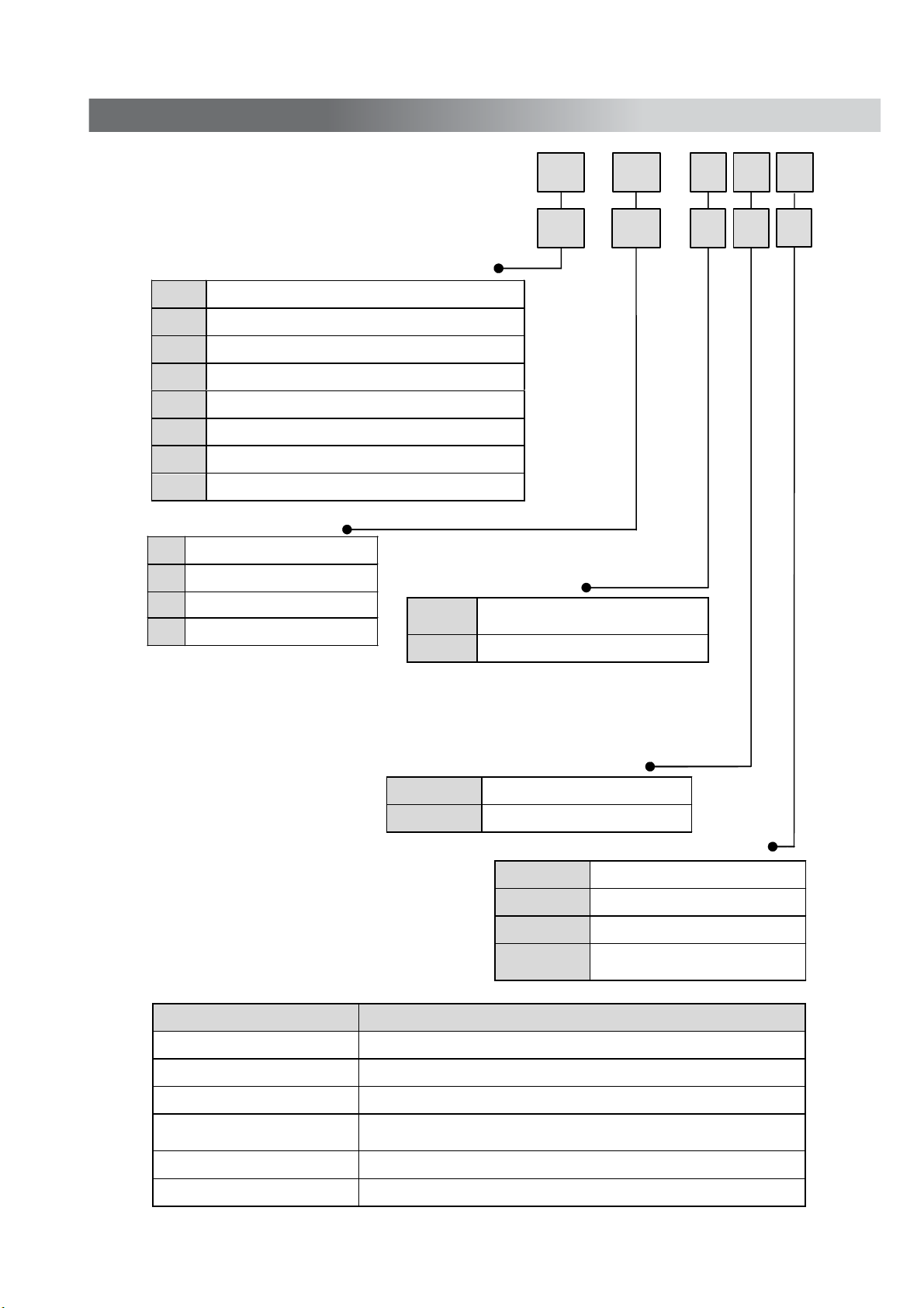
Model Indication Method
Model Indication Method
For positive pressure : I S E 3 0 − − −
01
25
For vacuum and low pressure : Z S E 3 0 − − −
01 25
01 R1/8 (M5 internal thread)
T1 NPT1/8(M5 internal thread)
C4H
C6H
N7H
C4L
C6L
N7L
25 NPN output
65 PNP output
26 1-5V analogue output
28 4-20mA analogue output
One-touch fitting φ4, φ5/32inch straight type
One-touch fitting φ6 straight type
One-touch fitting φ1 /4 inc h st raight type
One-touch fitting φ4, φ5/32inch elbow type
One-touch fitting φ6 elbow type
One-touch fitting φ1 /4 inc h elb o w type
Output Specification
Optional Indications
Option Model number
Pipe S pecification
Unit S pecification
No
symbol
M Note2) SI units only
Note1) The new Measurement Law prohibits use in
Japan of pressure switches with a unit selection
function.
Note2) Fixed unit for vacuum and low pressure is : kPa
for positive pressure is : MPa
No symbol
L
Note1) Unit selection function
Option 1
No Lead wire with connecto r
Lead wire with connector
No symbol None
A Bracket
B
D
Panel Mount Adapter
Panel Mount Adapter
+ Front Face Protective Cover
M M L
Option 2
A
Lead Wire with Connector ZS-27-A (Lead wire with Connector : 2m)
Bracket
Panel Mount Adapter ZS-27-C
Panel Mount Adapter +
Front Face Protective Cover
Front Face Protective Cover
Panel Mount Adapter1 ZS-27-02
ZS-27-B (Contained mounting screws : M3×5L 2pcs.)
ZS-27-D
ZS-27-01
-7-
PS##-OMF0010-C
Page 9

A
p
p
@
Specification
ZSE30 ISE30
Rated Pressure Range
Set Pressure Range
Withstand Pressure 500 kPa 1.5 MPa
Setting and Display Resolution
Fluids Air, inert gases and incombustible gases
Power Supply Voltage
12 to 24V DC, ±10%,ripp le (p
Current Consumption 45mA or less (No load)
Switch Output Note 1) NPN or PNP open collector output .1 output
Max. Load Current 80mA
Max. Impressed Voltage
Residual voltage 1V or less (@80mA load current)
Response Time
Short Circuit Protection
2.5ms
Repeatability
Voltage Output
Note 2)
nalog
Output
Hyster
esis
Current Output
Note 3)
Hysteresis Mode
Window Comparator
Mode
Max. Load Impedance : 300Ω (@12VDC), 600Ω (@24VDC) Min. Load Impedance : 50Ω
Display Method 3.5 digits 7-segment display, dual-color display(red/green) Sampling rate:5 times/1 sec
Indicator Accura cy
Indicator Lamp Lit when ON (Green)
Temperature Characteristic
Enclosure IP40
Ambient Te mperature
O
Ambient Humidity
Withstand Voltage 1000VAC,1 minute (between lead block and case)
Insulation Resistance
Vibration proof
Environment
Impact proof 100m/s
10 to 150 Hz, 1.5mm double amplitude, 2 hours each in directions of X, Y and Z respectively
Standard
Note 1) Analog output cannot be selected when switch output is selected.
Note 2) Both switch output and current output cannot be selected simultaneously when voltage output is
selected.
Note 3) Both switch output and voltage output cannot be selected simultaneously when current output is
selected.
-
100 to 100 kPa 0 to 1 MPa
-
101 to 101 kPa
-
0.1 to 1 MPa
0.2 kPa 0.001 MPa
-
p) 10% or less(Protected against inverse connection)
30V (During NPN output)
or less
(chattering
-proof function working :20,160,640 or 1280ms selectable)
Provided
±0.2%F.S. ±2 digits or less ±0.2%F.S.±1 digit or less
Output Voltage : 1 to 5V ±2.5%F.S. or less (within rated pressure range)
Linearity : ±1%F.S. or less, Output impedance : Approx. 1kΩ
Output Current : 4 to 20mA ±2.5%F.S. or less (within rated pressure range)
Linearity : ±1%F.S. or less
Variable(from 0)
±2%F.S. ±2 digits (@25±3°C) ±2%F.S. ±1 dig it ( @25±3°C)
±2%F.S. or less (@25°C reference)
eration : 0 to 50°C, Storage : -10 to 60°C (No condensation or no freezing)
O
eration⋅Storage : 35 to 85%RH (No condensation)
50MΩ or more
2
, 3 times each in directions of X, Y and Z respectively
500VDC M (between lead block and case)
CE marking, UL/CSA(E216656)
Piping specification
Model 01 T1 C4H C6H N7H C4L C6L N7L
Port size
One-touch fitting
straight type
One-touch fitting
elbow type
Material
Lead wires with
Mass
(Weight)
connector included
Lead wires with
connector not included
R1/8
M5×0.8
− −
− − − − −
Sensor pressure sensing part: silicone, Pipe port: C3602 (electroless nickel plating),
O-ring: HNBR
(2m)
NPT1/8
M5×0.8
− − − − − −
φ4mm
φ5/32inch
φ6mm φ1/4inch − − −
φ4mm
φ5/32inch
φ6mm φ1/4inch
O-ring: NBR O-ring: NBR, Fitting: PBT
81g 76g 78g
43g 38g 40g
-8-
PS##-OMF0010-C
Page 10

Full View with Dimensions
Full View with Dimensions
Dimensions of Main Unit
-9-
PS##-OMF0010-B
Page 11

Bracket supplied
Panel Mount Type
With Front face protective
-10-
PS##-OMF0010-C
Page 12

Panel Cut Dimensioms
-1 1-
PS##-OMF0010-C
Page 13

Names and Function of Individual Parts
Operation Indicator Lamp : Displays switch operation condition.
(Green LCD)
LCD Display : Displays the current status of pressure, setting mode, selected indication unit and error
code. Four display modes can be selected: display always in red or green
only , or changing
from green to red linked to output.
Button : Increases the mode and ON/OFF set value. Press this button to change to the peak display
mode.
Button : Decreases the mode and ON/OFF set value. Press this button to change to the bottom
display mode.
Button : Press this button to change to either mode and to set a set value.
Please refer to t he matter and the attach ed tab le c oncerning the se tting s inc e 17 page
for displayed character and value.
-12-
PS##-OMF0010-C
Page 14

Install using the special bracket (Article No.ZS-27-B) or the panel mount adapter (Article No.ZS-27-C)
available as options.
Caution : Tighten the pipe port at a clamping torque of 7 to 9N⋅m.
Fasten the bracket mounting screws at a clamping torque of 0.5 to 0.7N⋅m.
Mounting by Bracket
Mount the bracket on the main unit using the two
mounting screws M3 × 5L and install on the facility
using hexagon socket head cap screws.
Mounting procedure with the panel mount adapter
1. Mount the panel mount adapter (1) to the switch display
side.
Mount the panel mount adapter so that the adapter hook
engage with the groove of the switch.
2. Insert the switch from the front of the panel
for the switch mount hole.
3. Mount the panel mount adapter (2) to the switch
from the back of the panel.
Press the panel mount adapter (2) with a driver
to the panel for secure mount.
Panel mount adapter (2) can be mounted even
when rotated 90°.
4. Play can be reduced by using attached tapping screw.
Installation
-13-
PS##-OMF0010-C
Page 15

Notice when removing the switch
Digital pressure switch with adapter for panel mounting can be removed from facility by making
hook of the switch wide as following.
Pressure switch and Panel mount adapter may be damaged it you picked up the hook.
Piping connections
•Cut the tube perpendicularly.
•Grasp the tube, slowly push it into the One-touch fittings until it comes to a stop.
One-touch fitting
-14-
tube
PS##-OMF0010-C
Page 16

Example of Internal Circuit and Wiring
Output Specification
When the Lead wire with connect or provided by S MC CORPORATION is used, the color s of wire
(Brown, Black, Blue) will apply as shown on circuit diagram.
-15-
PS##-OMF0010-C
Page 17

Connector
Connector Connecting/Disconnecti ng
•When connecting the connector, insert it straight onto the pin holding the lever and connector body
between fingers and lock the connector by pushing the lever claw into the square groove in the housing.
•When disconnecting the c onnector, push down the lever by thum b to disengage the lever claw fr om the
square groove. Then pull the connector straight out.
•Please refer the table b el ow for t he connector cable (without connector).
Item Specification
Cable O.D. φ3.4
Core no. 3
Conducted normall y
sectional area
0.2mm
2
(A WG25)
Complying standard Complies UL2103
End of terminal
•Use SMC specified connector cable.
If you need different length of lead wire, please contact to SMC sales person.
-16-
PS##-OMF0010-C
Page 18

Setting
Setting Procedures
Initialize
Press the button continuously for more than two seconds.
The display shown at the right will pop up to allo w sett ing of
a display color.
In the case that the unit specification of model indication is M,
the SL units will be fixed. If no s ymbol is s upplied, see
”Selecting Indication Unit.”
1. Display Color Setting
Select a color for the LCD display .
When changing the display color, press the or button
to select a display color.
Sor (Red/ON) SoG (Green/ON)
rED (Red) Grn (Green)
Press the button to set the desired display color and to move on to setting a desired operation mode.
If the mode is set to analog output , press the or button, to select a desired display color from
“Grn (Green) ⇔ rED (Red), then press the button. Setting of a desired operation mode will become
available.
2. Operation Mode Setting
A desired switch operation mode can be selected.
The operation mode currently selected will be displayed. Select a desired operation mode by pressing
the or button.
(Hysteresis) (Window Comparator)
Press the button to move on to setting an output node.
3. Auto Preset Setting
A desired output mode can be set freely for switch output.
The output mode currently selected will be dis p layed.
Press the or button to switch to normal output “no” or reverse output “nC”.
(Normally open) (Normally closed)
Press the button to move on to setting a desired response time.
Setting
Measurement Mode
-17-
PS##-OMF0010-C
Page 19

4. Response Time Setting
A response time for switch output can be set as user desires.
Setting of a response time prevents chattering output.
The response time currently set will be displayed. Select a desired response time by pressing
the or button.
(2.5ms) (20ms) (160ms) (640ms) (1280ms)
Press the button to set and move on to setting Auto Preset mode.
If the operating mode is set to Hysteresis, press the button to set and return to Measurement mode.
5. Auto Preset Setting
This function stores in the memory a measurement pressure as a reference value when Auto Preset
input is set.
The setting currently set will de displayed. Press the or button to set to Auto Preset.
(Manual Setting)
(Auto Preset)
Press the button to return to the Measurement mode.
Selecting Indication Unit (If the unit specific ation of the model indicati on i s without “M”)
The indication unit can be selected freely .
Pressing the or button will change the unit and will automatically convert set values.
The units will change in the following order : PA ⇔ GF ⇔ bAr ⇔ PSi⇔ inH ⇔ mmH
Press the button to set and to move on to setting a display color.
Resolution of each units
Setting and Displ a y
Resolution
ISE30 ZSE30
Pa 0.001MPa 0.2kPa
Kgf/cm2 0.01 0.002
bar 0.01 0.002
psi 0.2 0.05
mmHg
−
2
inchHg
−
0.2
-18-
PS##-OMF0010-C
Page 20

If set to Manual Setting
Press the button in the Measurement mode to display set values.
“P_1” or “n_1” and the current set value will flicker alternately.
Press the button to display the next set value.
Press the or button to enter into the Value Change mode.
(See “Value Setting”)
If Hysteresis mode is set
If the Hysteresis mode is set, “H” and the set value of Hystersis will be
displayed alternately after the setting for “P
_
1”.
Press the button to return to the normal Measurement mode.
Press the or button to enter into the Value Change mode.
(See “Value Setting)
In case Hysteresis is set at less than or equal to 2 digits, switch output may chatter if
input pressure fluctuates near the set point.
If window comparator mode is set
If the Window comparator mode is set, “P_2” or “n_2” and the current
set value will be displayed alternately after the setting for “P
_
1”.
Press the button to display the next set value. (Hysteresis : H)
Press the or button to enter into the Value Change mode.
(See “Value Setting”)
Next, “H” and the set value of Hysteresis will be displayed alternately.
Press the button to return to the normal Measurement mode.
Press the or button to enter into the Value Change mode.
(See “Value Setting”)
If the initialize value is the Normally Open mode, “P_1” will be displayed. “n_1” will be displayed
if it is Normally Closed mode. The set pressure value can be checked without holding or stopping
switch output operation.
Pressure Setting
-19-
PS##-OMF0010-C
Page 21

If set to Auto Preset Mode
Press the button during the Measurement mode to ready Auto Press mode and
“AP1”will be displayed. Setting pressure in this condition will ready the equipment.
Press the and buttons simultaneously while “AP1” is displayed to return to the
measurement mode.
To execute Auto Preset, press the button and “A1L” will be displa yed. Perf orm
adsorption and desorption oper at ions . Detec t ion will b e m ade and a set value wi ll be
stored in the memory automatically.
Press the button while “A1L” is displayed to finish setting and to return to the normal
measurement mode.
Value Setting
To input value for pressure setting or other purposes:
1. Press the or button to enter the Set Value Change mode. The first row will flicker.
2. Press the or button to set a desired value.
(No operation within ten seconds after the Set Value Change mode was selected
results automatic setting of the value appearing in the display window and in charging
of the mode from Set Value Change mode to Set Value Indication mode.)
3. Press the button to make the value one digit higher flicker.
( If the highest place is zero, “ “ or “ “ will flicker.“ “ means “+zero”,
“ “ means “-zero”, " " means "-1")
(In the case that the button is pressed in the highest place, the first digit will flicker.)
4. Press the button continuously for longer than one second to return to displaying
set values.
Fine Adjustment Mode
(Fine Adjustment Function of Display Value)
Press the button and buttons simultaneously
for longer than two second in the Measurement mode.
“FSt” and current pressure Measurement value will be displayed.
Press the or button to change the set value.
If no operation is made for longer than two seconds or press the
set button, the pressure switch will display the current pressure
Measurement value which will then flicker adjusted with “FSt”.
Press the button to
display an adjusted amount (percentage),
which will then flicker alternately with “FSC”.
Press the button to return to the normal Measurement mode.
This function wake no dispersion each output value.
It is possible to fine adjustment within ±5% (ISE), ±2.5% (ZSE)
range of the reading data on the displayed value of pressure sensor.
Note) When fine adjustment function is conducted, pressure
setting value is sometimes changed by ±1 digit.
-20-
PS##-OMF0010-C
Page 22

Peak And Bottom Hold Display Function
Maximum and minimum values are always detected and updated during measurement.
Displayed values can be held. In peak hold, press the button for longer than one second to make
flicker and to hold the maximum pressure value.
To reset holding, press the button again for more than one s ec ond. The Measurement mode will be set.
In bottom hold, press the button for longer than one second to make flicker and to hold the minimum
pressure value.
To reset holding, press the button again more than one sec ond. The Measurement mode will be set.
Key Lock Function
This function prevents malfunction such as a set value being changed by
mistake. Press the button for longer than four seconds to display which
of “Loc” or “UnL” is currently set.
Select by pressing the or button and set by pressing the button.
If button operation is not desired, set to “Loc” to set the Lock mode.
To release key lock, press the button for longer than four seconds to
display the current setting and to “UnL”.
Zero Clear Function
A displayed value can be adjusted to zero when pressure to be measured is within ±70digits of the atmospheric
pressure.
(The range of ±10% F.S. setting is different depending on the individual product difference)
This function is useful because it enables detecting pressure fluctuations larger than a certain level without being
influenced by fluctuations of source pressure. Press continuously the and buttons simultaneously to reset
“0” on the display. To return to the Measurement mode, remove the fingers from the buttons.
Error Display Function
This function displays error location and nature when a problem or an error occurs.
Error Name Error Displ a y
Error Nature Troubleshooting Method
Overcurrent
Error
A load current of switch output is flow
80mA or more.
Turn the power off and remove the
Output factor for the overcurrent.
Then turn the power on.
Residual
Pressure
Error
Pressure more than ±0.071MPa for
1MPa or more than ±7.1kPa for vacuum
compared with the atmospheric
pressure is applied during zero clear
operation.
In three seconds, the mode will reset
to the Measurement mode. ±10%F.S.
of the setting range changes
with individual pr oduct differences.
Preform zero-clear operation
Again after restori ng the applied
Pressure to an atmospheric
Pressure condition.
Pressure exceeding the high limit
of the set pressure range is applied.
Pressurizing
Error
Pressure exceeding the low limit
of the set pressure range is applied.
Reset applied pressure to a level
Within the set pressure range.
Displayed in the case of an
internal data err or.
Displayed in the case of an
internal data err or.
Displayed in the case of an
internal data err or.
System Error
Displayed in the case of an
internal data err or.
Turn the power off and turn
it on again.
If resetting fails, an investigation
By SMC CORPORATION
Will be required.
Other Function
-21-
PS##-OMF0010-C
Page 23

1.
Display color
Display
Display
character
Meaning
Sor
When turning it on,
it red displays it.
SoG
When turning it on,
it green displays it.
rEd
Red
Grn
Green
2.Output mode
Display
Display
character
Meaning
no
Normal open
nc
Normal close
3.Key lock
Display
Display
character
Meaning
Loc
Lock
UnL
Unlock
4. A uto Preset
Display
Display
character
Meaning
Aut
Auto Preset is selected.
AP1
State of preparation of
Auto Preset
A1L
Auto Preset is being set.
Setting of figure
(Display of segment in left end)
Display
Display
character
0
-0
1
-1
Setting of figure
(Display of segment of treble)
Display
Display
character
0.012
0.345
0.678
0.900
Attached Table
PS##-OMF0010-C
Page 24

5.Manual set
Display
Display
character
Meaning
mAn
Manual set
Hys
Hysteresis mode
(Display when operation mode is set)
Wnd
Window comparat or mode
(Display when operation mode is set)
P_1
Hysteresis mode and
Window comparat or mode
(When P_1 of the setting of pressure is
set, it display s it.)
P_2
Window comparat or mode
(When P_2 of the setting of pr essure is
set, it display s it.)
n_1
Hysteresis mode and
Window comparat or mode
(When n_1 of the setti ng of pressure is
set, it display s it.)
n_2
Window comparat or mode
(When n_2 of the setti ng of pressure is
set, it display s it.)
H
Display when pressure is set
6.Fine Adjustment Mode
Display
Display
character
Meaning
Fst
When the adjustment amount is
set and, it displays it in the place
where the minute adjustment
mode is selected.
Fsc
Amount of adjustment
(Display it by percent. )
PS##-OMF0010-C
 Loading...