

Page 1
INSTALLATION AND OPERATION INSTRUCTIONS FOR ZER O CLEARANCE
AND FREE STANDING UNITS
FS-26-922
SAFETY INFORMATION
WARNING
If the information in these instruction s are
not followed exactly, a fire or explosion
may result causing property damage,
personal injury or loss of life.
Do not s tore or use gasoline or other flammable vapors
and liquids in the vicinity of th is or any other applian ce.
INS T ALLER: LEAVE THIS M ANUAL WITH THE APPLIANCE.
CONSUM ER: RETAIN THIS M ANUAL FOR FUTURE REFERENCE.
Page 2

2
TABLE OF CONTENTS
Please read and carefully follow all of the instruction found in this manual. Please pay special
attention to the safety inst ructions provided in this manual. The ins tructions included he re wi ll
assure that you have many years of dependable and enjoyable service from your Sierra flame product.
IMPORTANT INSTRUCTIONS....................................................................................................................................3
UNPACKING AND TESTING APPLIANCE...............................................................................................................3
GROUNDING APPLIANCE.........................................................................................................................................4
LOCATING THE FIREPLACE.....................................................................................................................................4
FS-26-922.......................................................................................................................................................................
HARD- WIRE INSTALLATION...................................................................................................................................6
MEDIA OPTIONS.........................................................................................................................................................7
DECORATIVE MEDIA INSTALLATION....................................................................................................................7
OPERATION..................................................................................................................................................................8
MANUAL OPERATION................................................................................................................................................8
REMOTE CONTROL OPERATION.............................................................................................................................9
INSTALLING WALL THERMOSTAT........................................................................................................................10
REPLACEMENT PARTS............................................................................................................................................12
EXPLODED VIEW......................................................................................................................................................13
WIRING DIAGRAM...................................................................................................................................................14
TROUBLE SHOOTING..............................................................................................................................................15
SERVICE HISTORY....................................................................................................................................................16
WARRANTY...............................................................................................................................................................17
5
Page 3

3
IM POR T ANT INS TRUCTIONS
Read all inst ructions before installing or using this heater.
2. Keep combustib le materials, such as fu rniture, pillows, bedding, papers, clothes and curtains at
least 3 feet f rom the front of the heater; keep them away from sides and rear as well.
3. Always unplug heater when it’s not in use.
4. Do not operate the firep lace if it has a damaged cord or plug, after it has malfunctioned, or if the
unit h as been dropp ed or damaged in any way.
5. Do not use the heater outdoors.
6. This heate r is not intend ed for use in bathrooms, laundry areas and similar indoor locations.
Never place the heater where it may fall into a bathtub or other water containers.
7. Do not run the cord under carpeting. Do not co ver the cord wit h throw rugs, runners or an ything
else. Arrange the cord away from traffic areas where it could not be tripped over.
8. To disconnect t he heater, turn the controls to "OFF" before removing the plug from the outlet.
9. Do not insert or allow foreign objects to en ter any vent ilation or exhaust opening, as this may
cause an electric shock, fire or damage to the heater.
10. To prevent a possible fire, do not block air intakes in any manner.
11. A heater has hot and arcing or sparking parts insid e. Do not use it in areas where gasoline, paint
or f lammable liquids are u sed or stored.
12. Use this heater only as de scribed in this manual. Any other use not recommended by the
manufacturer may cause fire, electric shock or injury to persons.
13. Avoid th e use of an extension cord be cause the extension cord may overheat and cause a fire.
14. Always use properly grounded fused an d polarized outlets.
15. Always use ground fault protection where it is required by electrical codes.
16. Always disconne ct the power before performing any cleaning, maintenance or relocation of the
he ater.
17. To prevent a possible fire, do not burn wood or other materials in this heate r.
18. To prevent electric shock or fire, always use a certified electrician, should new circuits or outlets
be required.
When transporting or storing the heater, keep it in a dry place, free from excessive vibration.
UNPACKING AND TE STING APPLIANCE
Caref ully remove the app liance from the box.
Prior to ins talling the appliance, tes t to make s ure the appliance operates properly by plu gging the
power supp ly cord into a c onveniently lo cated 120 Volt grounded outlet.
Tes t all aspects of its operation (manual switches, remote and heater) to make sure all components
operate corre ctly.
1.
19.
Page 4

4
GROUNDING APPLIANCE
This appliance is for use on 120 Volts. The cord has a plug as shown in (A). An ad apter as shown in (C)
is available for connecting three-blade grounding type plugs to two-slot receptacles. The green
grounding lug extending from the adapter must be connected to a permanent ground such as a
properly grounded outlet box. The adapter should not be us ed if a three-slot grounded receptacle is
available.
To disconnect appliance, turn co ntrols to off,
then remove plu g from outlet.
LOCATING THE FIREPLACE
Plan where to locate and frame the fireplace. Consider the following:
1. Consider a location where the fireplace screen will not be expo sed to direct sunlight from
windows or doors.
2. A 15 ampere, 120 Volt, 60 Hz branch circuit with proper ground must be available at the location.
Preferably a dedicated branch circuit should be pro vided to avoid circuit breakers to trip of fuses
to blow.
Page 5
5
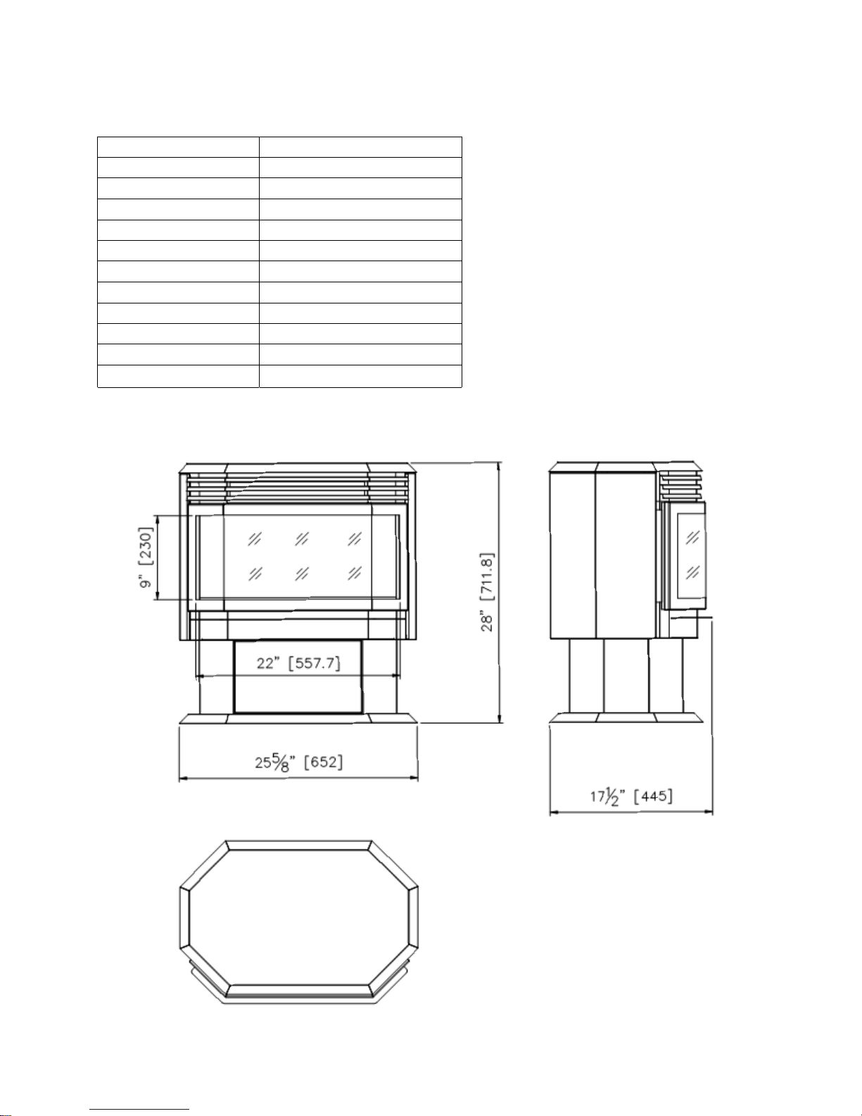
FS-26 -922
Description Free Standing Ap pliance
Voltage 120V AC 60Hz
Watts 1500W Max
NO HEATER 25W
MOTOR HEATER 19W
Appliance W idth 25 5/8" or 65.2 cm
Appliance Height 28" or 7 1.2 cm
Appliance Dep th 17 1/2" or 44.5 cm
Gross Weight 71.6 lb s or 32.5 kgs
Plug Location Left side
Co rd Length 70 7/8” or 180 cm
This appliance has been tested in
accordance with the UL Standard 2021
for fixed and locatio n dedicated
elect ric room appliances in the United
States and Canada. If you need
assistance during installation, p lease
contact your local dealer.
BTU
4800
NOTE: This appliance must be
electrically wired and grounded in
accordance with local codes. In the
absence of local codes, use the
current CSA C22.1 Canadian Electrical
Code in Canada or the ANSI/ NFPA 70
National Electrical Code in the United
States.
Page 6
6
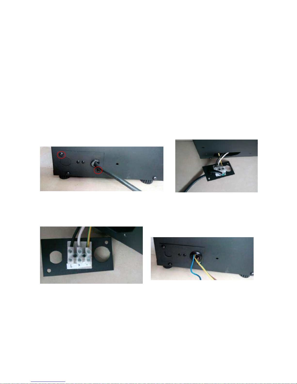
HARD- WIRE INS T ALLATION
Turn off t he appliance completely and let cool before servicing. Only a qualified service person
should service and repair t his electric appliance.
If it is necessary to hard wire this appliance, a qualified electrician must remove the cord connection ,
and wire the appliance directly to the hou se hold wiring.
This appliance must be electrically connected and grou nded in accordance with local codes, if hard
wired . In the absence of local codes, use the current CSA C22.1 CANADIAN ELECTRICAL CODE in
Canada or the current ANSI/NFPA 70 NATIONAL ELECTRICAL CODE in the United Stat es.
1. R emove the cover plate from th e left side of the appliance by removin g the two screws, as
shown below. Unscrew and remove p ower cord.
2. Attach th e wiring to the junction block. Please make sure the live wire goes into the "L", the
neutral wire into "N" and the ground wire into "G".
3. Put the plate back and screw back.
Page 7

7
M EDIA OPTIONS
Sabl e
DECOR A TIVE MEDIA INSTALLATION
STEP 1: Unplug the unit from wall and make
sure controls are switched off.
STEP 2: Push upwards (as shows in bellow
picture) and re move the front pan el to decorate
your fireplace. Pour the decorative media into
the tray. Feel fre e to use any combination of fire
glass media that you find most appealing.
STEP 3: After finishing decoration, put back the
Lo g Set 11 pi e ces
Hold here firmly, then push upwards to take off
the front glass panel.
The glass panel is hooked by 2 hooks on each
side.
Then you can take off
the glass panel.
front glass panel.
Now you can start to decorate your fireplace
Y our fireplace shipped with th e following media:
3 bags of sable glass and an 11 piece log set.
Customers can decorate their fireplace
according to their wishes with supplied media.
This fireplace includes the following decorative
media:
Page 8

8
OPERATION
The fireplace can be operated either by the switch es located on the left front of th e fireplace unit or
by supplied remote control.
M ANUAL OPERATION
Push to reveal the manual control panel. (As shows in bellow picture)
1. The main power ON/OFF switch in position O, the fireplace is OFF .
2. When main power ON/OFF switch is at position I, the firep lace is ready to use.
3. Press the
button repeated ly to set the heater to desired heat setting. The heater indicator
LED will glow which shows the current heater sett ings.
a) RED 1500W HEAT OUTPUT
b) BLUE 750W HEAT OUTPUT
c) PURPLE AUTO MODE
Push here to open the manual control panel
AUTO MODE
Un der this mode the heater will automatically turn ON at high heat setting 1500 W heat ou tput when
the room temperature d rops below 22℃(72℉ ). When the room temperature is b etween
22-25℃(72-77℉ ) the heater output will switch to low heat setting 750W. When the room
temperature goes above 25℃(7 7 ℉) the heater will b e turned off and the cycle will continue. The
LED indicator will be PUR PLE in colour under this mode .
4. Flame effect: Press the button marked
to adjust the flame brightness. The flame brightness
will cycle through –Lo w-Medium-High -OFF .
5. Mood light effect: Press the butto n marked
to change the mood light colour.
Page 9

9
NOTE: If operated at the Low heat setting, the fireplace will not provide as much heat output as in
the High heat setting, however the low settin g will not require as much electrical power to op erate.
To avoid overloading a circuit, d o not plug the firep lace into a circuit that already has other
appliances working. When the fireplace is not in use switch off and unplug.
SAFETY CUT-OFF
l This appliance is fitted wit h a safety cu t-off which will operate if the fireplace overheats (eg. Due
to blocked air vents). For safety reasons, the fireplace will NOT automatically reset .
l To reset the appliance, disconnect the appliance from the main supply for at least 10 minutes.
R econnect the supply to the main and switch on the appliance.
REM OTE CONTROL OPERATION
For remote to function make sure the heater is plugged in and main power switch is turned to the
ON position, located on th e front bottom behind the panel.
When operating the remote make sure you point the remote to the centre of the fireplace and make
sure each time you press the button, t he buzzer inside the unit will beep once. It takes some time for
the receiver to respond to the transmitter. Do not PRESS the buttons more than once within two
seconds for correct operation.
DISPLAY ON/OFF button: Switching the fireplace flame and tray light ON/OFF. It has
functions of setting memory.
DISPLAY BLUE button: Adjust the blue color brightness of flame and tray.
DISPLAY YELLOW button: Adjust the yellow color brightness of flame and tray.
DISPLAY ORANGE button: Adjust the orange color brightness of flame and tray.
MOOD LIGHT ON/OFF button: Switching the mood light ON/OFF.
ADJUST button: Switching the color of the mood light.
Power on
button: The power-on button at top left corner of the remote is the main
ON/OFF power button. This will turn off all the functions and the fireplace will be in standby
mode.
Page 10

10
INSTALLING WALL THERMOS T AT
WALL THERM OST AT WIRING DIAGRAM S
NOTE: THE WALL THERMOST AT WILL WORK ONLY WHEN THE HEATER IS SET TO TEM P. SETTING
PLEASE REF ER TO THE M ANUAL CONTROL AND THE REM OTE CONTROL.
W ire the wall thermos tat prior to installing the fireplace.
WALL THERM OST AT WIRING(24 VAC)
Install Wall Thermostat per instructions provided with kit and per the following information:
1. Turn off circuit breaker.
2. R emove cover plate located on the left up side of ap pliance.
3. Pull the wire out and cut the insid e thermostat. Connect the wires to the wall thermostat as
shown below. Follow instructions provided with wall switch kit .
FLASH button: Switches mood light into flash mode, this cycles through all mood light colors.
HEATER ON/OFF button: Switching the heater ON/OFF. It has functions of setting memory.
HIGHT button: Press the high button to switch the heater to high heat setting 1500W.
LOW button: Press the low button to switch the heater to low heat setting 750W.
TEMP. button: Press the TEMP. button to switch the heater to AUTO mode. Under this mode
the heater will operate in similar way as explained above for the manual operation.
Page 11

11
Page 12

12
REPLACEMENT PARTS
This list contains replacement parts
NO. PART NUMBER DESCRIPTION QTY.
1 10701213 FRONT CLEAR GLASS (MIDDLE) 1
2 10701214 FRONT CLEAR GLASS (SIDES) 2
3 10702166 BOTTOM GLASS 1
4 BACK BLACK PLASTIC GLASS 1
5 10104002 SWITCH 1
6 FLICKER ASSEMBLY 2
7 10101201C FLAME MOTOR 2
8 601137B LED STRIP FOR TRAY 1
9 601136B LED STRIP FOR FLAME 2
10 3001506B REMOTE RECIVER 1
11 602030C BLOWER AND HEATER ASSEMBLY 1
12 601097B CIRCUIT BOARD 1
13 601036 MANUAL CONTROL 1
14 TOP LIGHT 1
15 10105063 REMOTE 1
3126010
3126512
10125025
Page 13

13
EXPLODED VIEW
Page 14

Wiring Diagram
14
Page 15

15
TROUBLE SHOOTING
PROBLEM POSSIBLE CAUSE SOL UTION
Flame LED’s are burnt out Inspect the LED’s and replace them if
ne cessary.
Dim or no flame
Back black cloth is falling off
and rolled up in the flicker
Change a flicker and back black cloth.
Ember bed is not
glowing or dimming
Ember LED’s are burnt out Inspect the ember bed LED’s and
replace them if necessary.
Appliance has overheated and
safety device has caused the
the rmal switch to disconn ect
Turn off the main switch, allow
appliance to cool for 10 minutes, then
turn it on.
House circuit breaker has
tripped
R eset house circuit breaker.
Appliance turns off and
will not turn on
Appliance’s fuse has blown Replace the fuse.
Appliance is not plugged into an
elect rical outlet
Check plug and plug in.
Appliance has overheated and
safety device has caused the
the rmal switch to disconn ect
Turn off the main switch, allow
appliance to cool for 10 minutes, then
turn it on.
Appliance will not come
on when switch is
flipped to ON
Circuit board is burnt out Inspect the circuit board and replace
it if necessary.
No warm air coming out
of appliance
Heater is burnt out Inspect the burner and heater
assembly and replace it if necessary.
Flame sputters
Flame motor is defective. Call a qualified service tech nician and
replace flame motor.
R emote Control does
not work.
Low batteries.
Un it switch in “O” position.
R eplace AAA batteries in remote
control.
Turn the switch in “I” position.
Flame is fixed. W iring may be loose or the
flame motor may be defective.
Page 16

16
SERVICE HISTORY
This heater must be ser viced annually depending on usag e.
Date Dealer
Name
Service technician
Name
Service P erformed Special Concerns
NOTES:
Page 17

17
 Loading...