

Sienci Labs Mill One V2 Assembly & Instruction Manual
Mill One V2
Assembly Manual

Throughout this policy the words "we", "us" and "our", or “Sienci Labs” will be used to refer to Sienci Labs Inc. herein and
“Mill One” or “machine” will refer to Sienci Labs’ Sienci Mill One product. Additionally, the words "you", "your", “user”,
and “operator” will refer to the original purchaser/customer, user, or viewer of any of the products or media provided by
or through Sienci Labs.
Machine Disclaimer
The listed “Safety Warnings and Guidelines” outline the necessary precautions that should be taken any time the
machine is operated. By assembling our provided kit, the product user takes on all the associated liability pertaining to
the operation and maintenance of the Mill One. Sienci Labs will not be held responsible for any damages to property or
injury incurred on the operator or bystanders if any alterations are made to the design or assembly of our machine.
Although care is taken to ensure the accuracy of information made available on our website (www.Sienci.com) and other
forms of media, Sienci Labs will not be held liable for any inaccuracies, errors, or inconsistencies in website content, the
content of files linked to by our website, references made to external websites herein, and/or other information
produced by Sienci Labs. The information which has been made available will not be applicable to all situations and is
subject to change without notice so it should not substitute for the discretion of the user. Variability in machine accuracy
and performance may occur due to improper machine assembly by the user, as such, Sienci Labs takes on no
responsibility for variation between claimed machine specifications and the performance of the user’s machine from
improper assembly.
Safety Warnings and Guidelines
1. Be sure to carefully follow provided machine assembly instructions before machine use to ensure operator
safety.
2. All wires must be appropriately positioned before beginning the operation of this machine. Cutting a “live” wire
may cause exposed metal parts of the routing/trimming tool to become electrified and shock the operator.
3. Ensure the machine is placed on a flat surface and in a well-ventilated space before operation.
4. Always wear eye protection during machine operation.
5. Always wear hearing protection during extended machine operation based on proximity to machine.
6. Materials may release chemicals that are toxic or unsafe to inhale when cut. Always check the Material Safety
Data Sheet (MSDS) of the material in question before cutting. Always cover exposed skin and wear appropriate
airway protection (e.g. dust mask/respirator) specific to the material used and its application.
7. Any workpiece must be appropriately secured before starting a cutting routine by clamps or other practical
securing method. Holding the material by hand or employing any any other unstable form of securing will lead to
unsafe loss of machine control.
8. Cutting bits used for the Mill One should be used at the discretion of the user. Bits are sharp and can crack and
break without notice so appropriate care should be taken by the user while manipulating and installing them.
Carefully check bits for cracks or damage before operating the machine and replace any cracked or unfit bits
immediately.
9. Carefully inspect any consumable material before use on the machine, any unforeseen inconsistency in material
hardness or material quality may cause damage to the machine.
10. Keep away from all moving parts during machine operation.
11. Before beginning a cutting job, ensure the router/trimmer runs properly. Immediately disable the tool if visible
vibration or wobble occurs. This might indicate a damaged tool or an improperly installed bit.
12. Make sure the bit is not contacting the workpiece before the router/trimmer tool is turned on.
13. Do not leave the machine running unattended, the machine should only be operated with the operator present.
14. Do not touch the cutting bit immediately after use. It may be hot and could burn the operator.
15. Use bits that are appropriate to the material and cutting speed used.
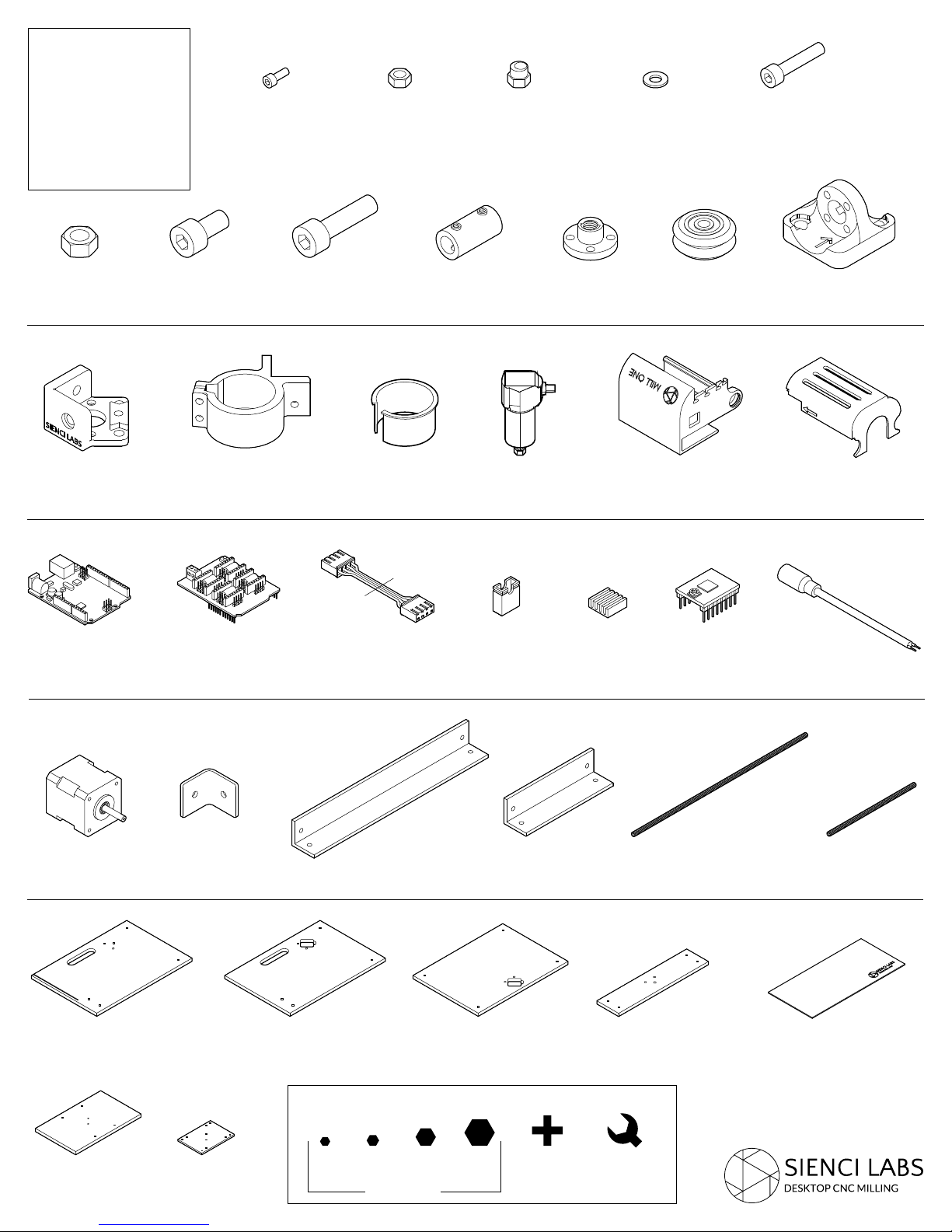
LIST OF
PARTS
M3-8
24x
M5-N
10x
M5-NE
6x
M5-W
12x
M5-25
16x
M8-N
10x
P-AM
5x
E-ARD
1x
M8-15
28x
P-RM
1x
E-CNC
1x
M8-25
10x
E-C
3x
P-RB
1x
SC
3x
RO
1x
E-HJ
6x
A-N
3x
E-SDH
3x
P-EH
1x
VW
12x
E-SDC
3x
P-NH
3x
P-EC
1x
E-J
1x
SM
3x
F-L
1x
M-FB
8x
F-R
1x
Tools:
G-Y
1x
G-XZ
1x
2 2.5 4
AR-400
2x
Allen Keys
AR-200
1x
F-B
1x
6 Phillips
8mm
Wrench
F-F
1x
LS-400
2x
LS-200
1x
F-AC
1x
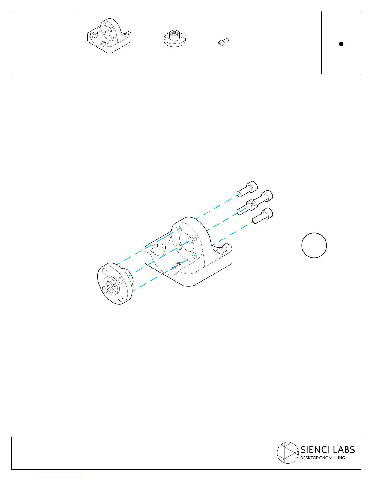
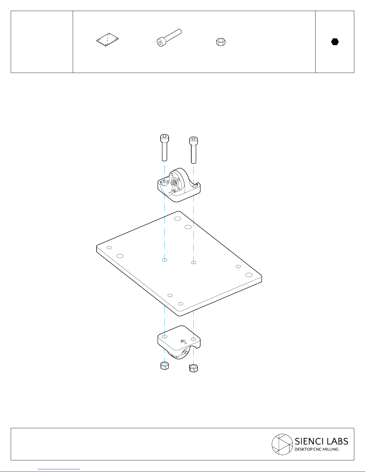
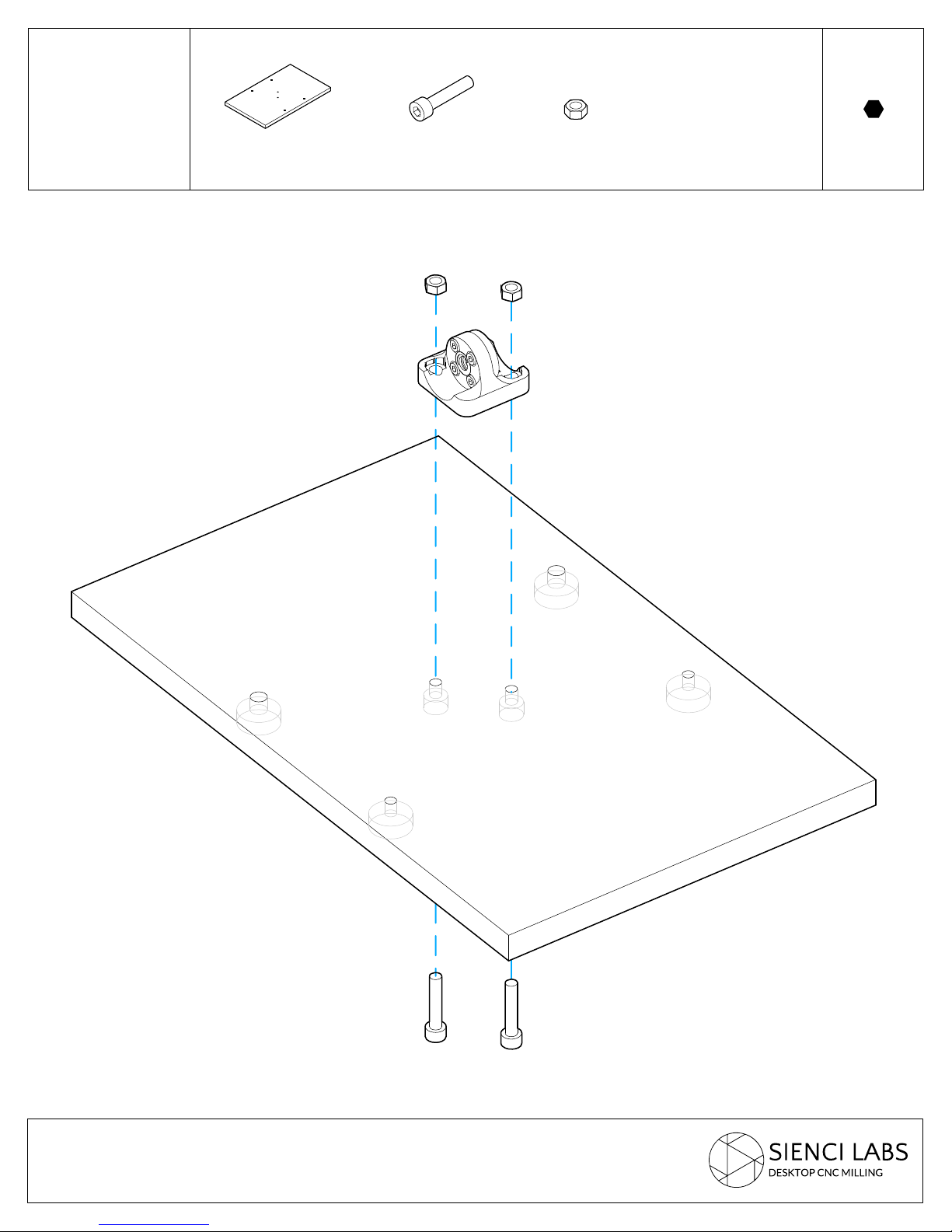
STEP 1
Lead Screw
Nut Holding
Assembly
P-NH
3x
A-N
3x
M3-8
12x
2.5
Allen
3x
STEP 2
XZ Gantry
Assembly
G-XZ
1x
M5-25
2x
M5-N
2x
4
Allen
STEP 3
Y Gantry
Assembly
G-Y
1x
M5-25
2x
M5-N
2x
4
Allen

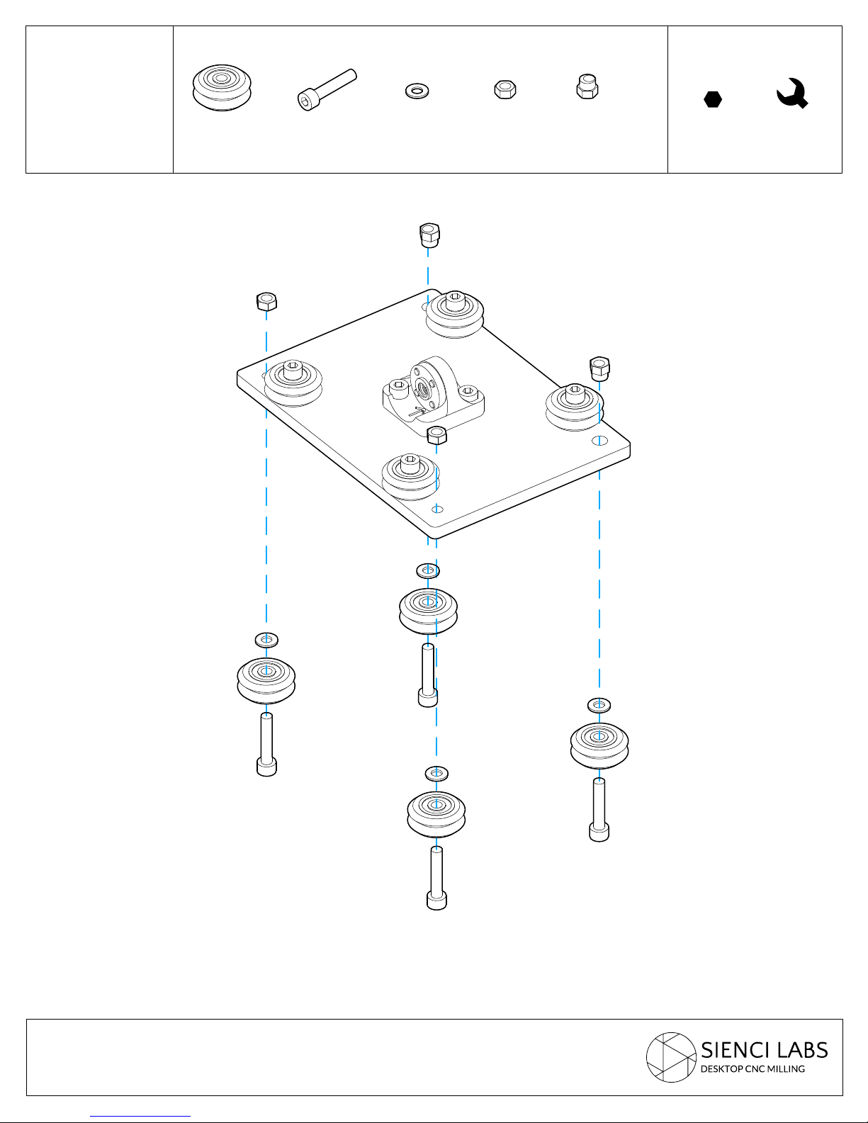
STEP 4
XZ Gantry
Assembly
VB
4x
M5-25
4x
M5-W
4x
M5-N
2x
M5-NE
2x
4
Allen
8mm
Wrench
Match the eccentric nuts (M5-NE)
!
to the larger holes, and the regular
nuts (M5-N) to the smaller holes
!
!
STEP 5
XZ Gantry
Assembly
VB
4x
M5-25
4x
M5-W
4x
M5-N
2x
M5-NE
2x
4
Allen Wrench
8mm
!
!
Match the eccentric nuts (M5-NE) to the larger
!
holes, and the regular nuts (M5-N) to the smaller
holes

STEP 6
Y Gantry
Assembly
VB
4x
M5-25
4x
M5-W
4x
M5-N
2x
M5-NE
2x
4
Allen Wrench
8mm
!
Match the eccentric nuts (M5-NE) to the larger
!
holes, and the regular nuts (M5-N) to the smaller
holes
!
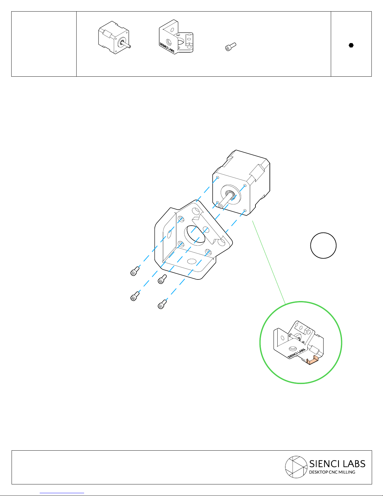
STEP 7
Mounting the
Motors to the
Rails
SM
3x
P-AM
3x
M3-8
12x
2.5
Allen
Make sure that the motor connector is facing
!
downwards
3x
!
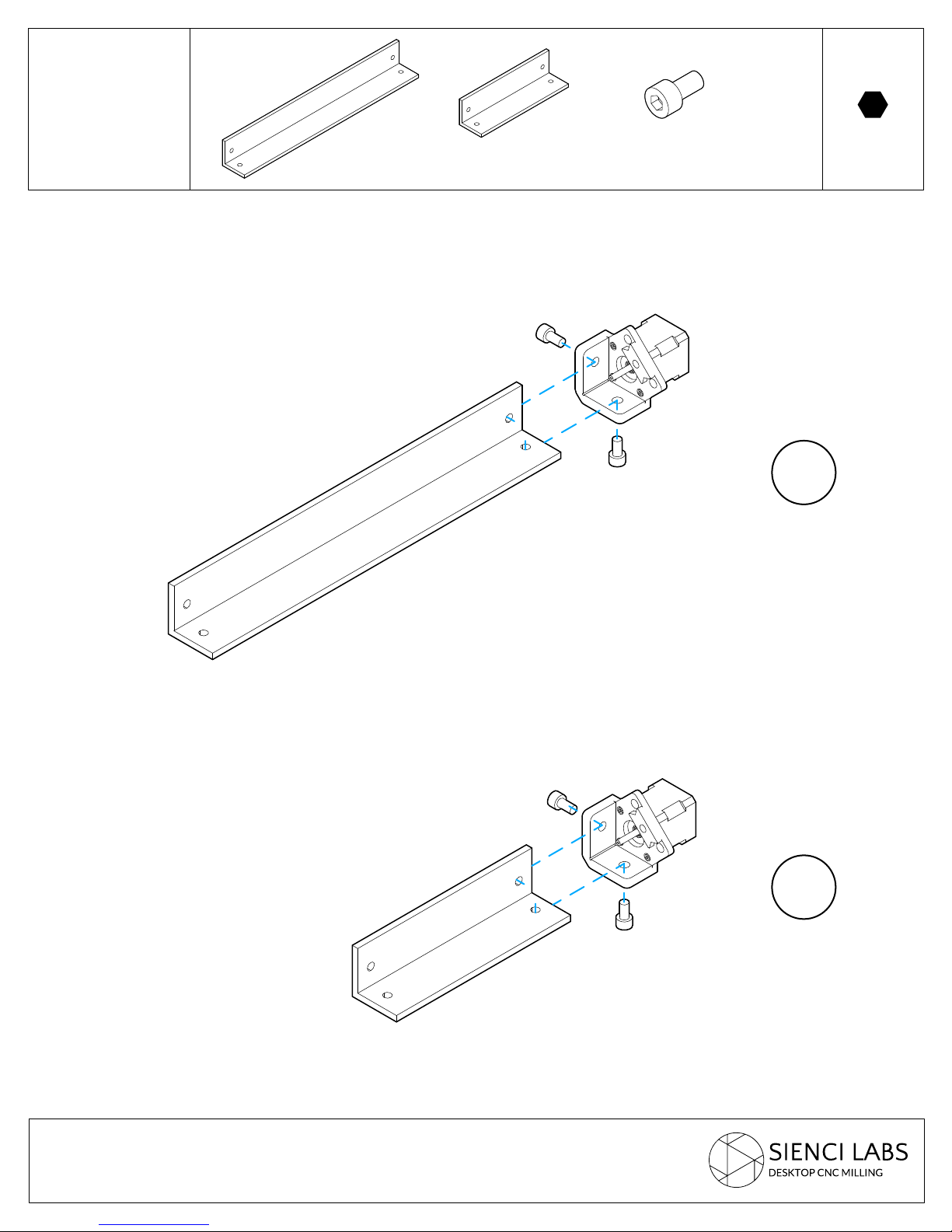
STEP 8
Mounting the
Motors to the
Rails
AR-400
2x
AR-200
1x
M8-15
6x
6
Allen
2x
1x
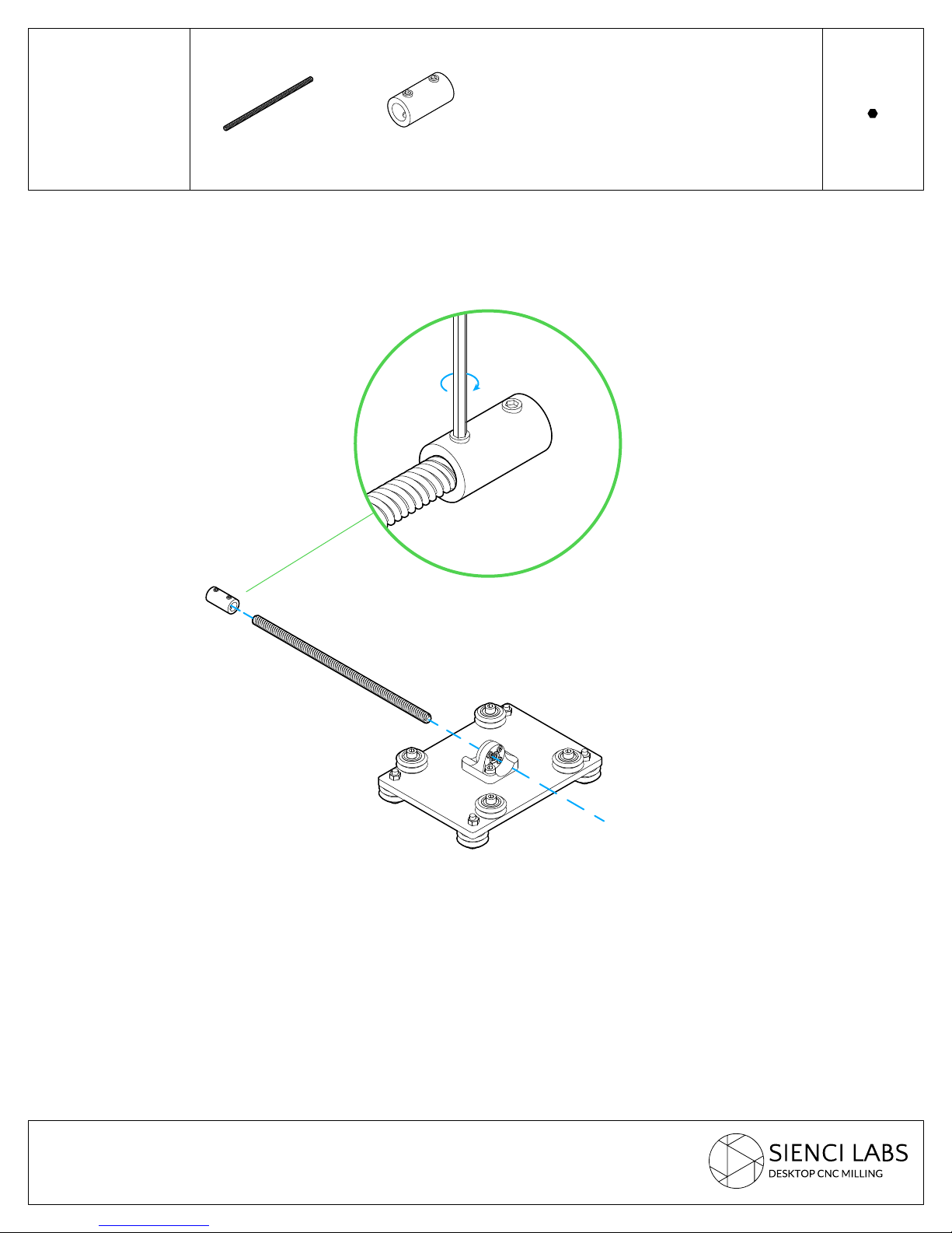
STEP 9
Attaching
Z-Lead Screw
to XZ Gantry
LS-200
1x
SC
1x
2
Allen
!
Make sure to push coupler all the way onto lead
!
screw before tightening
 Loading...