

Page 1

MapIT G2
Hardware Installation Training Manual
January 2019
Copyright Information
MapIT G2 is a trademark of the Siemon Company, with all rights reserved by the Siemon Company.
Some of the product names mentioned herein have been used for identification purposes only and may
be trademarks and/or registered trademarks of their respective companies. Information is subject to
change without notice. For the latest information, visit our Web site at http://www.siemon.com.
© 2015 Siemon Company. All Rights Reserved.
Page 2

MapIT G2 Hardware Installation Training Manual Confidential – June 2014
2
Table of Contents
Module 1: Hardware Components
Siemon MapIT G2 Intelligent Cabling Solution Overview 3
How the MapIT G2 System Works 6
MapIT G2 System Connectivity/Components 8
Master Control Panel (MCP) 12
Distribution Control Panel (DCP) 14
Smart Patch Panel (SPP) 16
Smart Fiber Enclosure (SFE) 18
Module 2: MapIT G2 System Design and Installation
System Design Guidelines 21
System Configuration Examples 26
MapIT G2 Site Survey 29
Site and Requirement Survey Forms 32
Summary of Design Rules 34
MapIT G2 Hardware Installation 35
Installing MapIT G2 Control Bus Cables 37
Module 3: Navigating the MapIT G2 Menus
Main Menu 40
Menu Navigation 41
Diagnostic Menu 42
Circuit Trace 50
Setup Menu 51
Mapping 56
Module 4: Troubleshooting the MapIT G2 Hardware Installation
Troubleshooting guide 59
Module 5: Documentation
Certifications 61
Technical Specifications 63
Warranty Information 65
Page 3

MapIT G2 Hardware Installation Training Manual Confidential – June 2014
3
Module 1: Hardware Components
MapIT G2 - Intelligent Cabling Solution
Introduction:
MapIT G2 intelligent hardware is used in conjunction with Siemon’s EagleEye software
and provides a complete Automated Infrastructure Management (AIM) system.
The objective of this manual is to provide information on how to properly install,
configure and use the MapIT G2 hardware. It does not provide a comprehensive
overview of the EagleEye software. Separate manual and training class are available
for EagleEye software. This manual covers these 5 key topics:
Module One; Hardware Components,
Module Two; System Design and Installation,
Module Three; Navigating the MapIT G2 Menus
Module Four; Troubleshooting
Module Five; Documentation
MapIT G2 Overview
Siemon’s MapIT G2 solution helps you better manage and protect your IT
infrastructure. The system tracks physical layer connections and IP enabled network
devices in real-time. While other software solutions may detect IP devices on the
network, they cannot track them to their exact physical location. The MapIT solution
provides a detailed view of your infrastructure, whether it is in your headquarters or at a
remote office on the other side of the world. This powerful combination of Siemon
intelligent cabling products and advanced software takes management of complex
data/telecommunications networks and critical applications to a new level.
This manual provides instruction on the MapIT G2 hardware. A separate EEC
software training program is available. Please contact Siemon if you would like to
arrange software training.
MapIT System Features
MapIT G2 Hardware is designed to work with Siemon’s EagleEye Connect and
EagleEye Enterprise software. This combination provides a comprehensive set of
network management capabilities.
Key features include:
Page 4

MapIT G2 Hardware Installation Training Manual Confidential – June 2014
4
Infrastructure Documentation
▪ Navigation Tree with hierarchical view of the infrastructure
▪ Graphical view of racks and cabinets
▪ Import floor images and overlay database items
▪ View complete circuit diagrams, including network devices
▪ Show network and power connections
▪ Real-time updates to the database
▪ Extensive search functionality
▪ Store virtually any asset in the infrastructure database
Physical Layer Monitoring
▪ Monitors and updates all MapIT patch panel/fiber enclosure connections in real-
time
▪ Provides a complete end-to-end circuit trace
▪ Quickly identifies the root cause of network troubles
▪ Maps active devices to their physical layer connection and location
▪ Automates the process of discovering, documenting, monitoring, and managing
the physical network’s connections and its devices
Asset Management
▪ Discovers and documents all IP enabled devices and ties them to a physical
location
▪ Reports switch port utilization and availability
▪ Reports physical Layer port utilization and availability
▪ Rack space reports, including available u space, available contiguous u space
▪ Tracks and reports on assets by type and/or location
Remote Site Management
▪ Automated database updates ensures accuracy of remote site infrastructure
documentation
▪ Views end-to-end circuit status remotely
▪ Work order status updated automatically
▪ Automated alerts on unauthorized activity
▪ View database from any compatible web browser
Improve Work Order Process
▪ Advanced work order capabilities allow you to create and manage tasks
▪ Technicians can view work orders on MapIT G2 equipment and get immediate
feedback on accuracy
Page 5

MapIT G2 Hardware Installation Training Manual Confidential – June 2014
5
▪ Automatic updates when work orders are completed
▪ Track costs for work orders by department
▪ Email/text alerts on email status
▪ SNMP traps alert 3
rd
party software of work order status
▪ Auto routing feature helps design the best path for new circuits or location in a
rack
▪ Greater efficiency reduces the cost of moves, adds and changes
Enhanced Security
▪ Detects when unauthorized devices connect to the network
▪ Monitors network for unauthorized activity such as patching changes, device
movement or device disconnection
▪ Wide variety of responses to unauthorized activity include email and text alerts,
snmp commands to disable switch ports, IP camera pictures
▪ Maintains an audit log of all network events
▪ EagleEye database can be backed up remotely and used for disaster recovery
How the MapIT G2 System Works
Smart Patch Panels (SPP) and Smart Fiber Enclosures (SFE) have the built in ability to
track patch connections. This connection information is transmitted to the Master
Control Panel (MCP) supporting the patch zone. The MCP relays this patch
connection information via TCP/IP over the customer’s LAN/WAN to the EagleEye
database. It is also possible to expand the capability of a given patching zone by
installing Distribution Control Panels (DCP) to support large numbers of SPPs and/or
SFEs.
Panel to Panel Communication
• Each port on a SPP or SFE has unique port ID. When two ports are connected
with a MapIT G2 Patch Cable or Fiber Jumper, the panels will sense the ID of
the connected ports and transmit that information back to the MCP/DCP
• The initial setup of the system will detect all ports within 2 minutes or less
• Subsequent changes are detected within 3 seconds
• Each SPP/SFE is connected to the MCP or DCP via a Control Bus Cable
Master Control Panel (MCP) Functions
• The MCP tracks new items that are connected in the Patch Zone (DCPs, SPPs
and SFEs)
• The MCP collects connection data from the panels in the Patch Zone
Page 6
MapIT G2 Hardware Installation Training Manual Confidential – June 2014
6
• It communicates via TCP/IP with the EagleEye database
• The MCP supplies power to SPPs and SFEs when connected directly to these
items. It does not supply power to DCPs.
Distribution Control Panel (DCP) Functions
• The DCP relays information on connected SPP/SFEs to the MCP
• Relays information on patch connections between SPPs/SFEs to the MCP
• Communicates with the MCP via a Control Bus Cable
• Supplies power to SPPs/SFEs
• The DCP has its own power supply. It is not powered from the MCP via the
Control Bus Cable
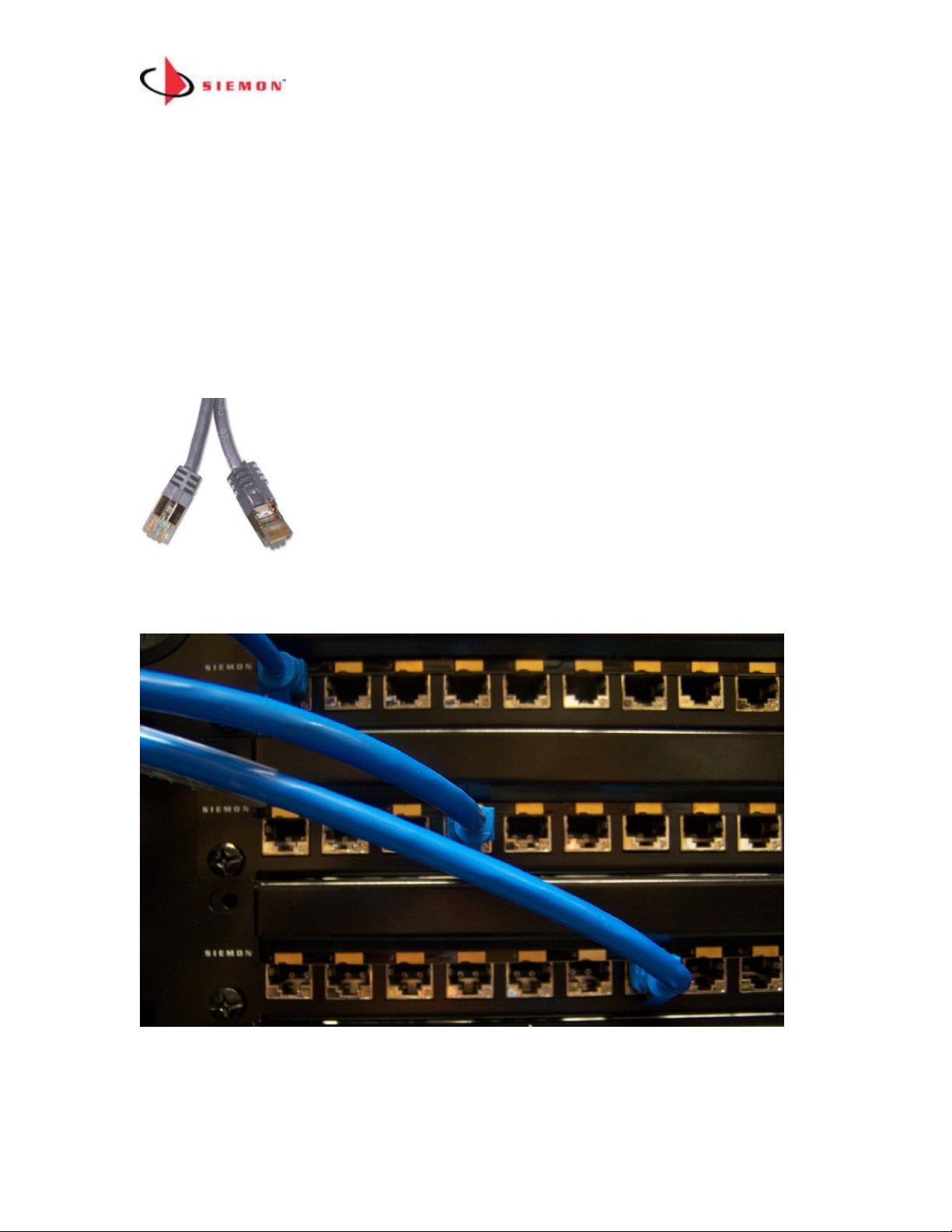
Patch Cord Connections Example:
When a MapIT G2 Patch Cable is inserted into a monitored port,
the probe located in the boot of the MapIT G2 Patch Cable
touches the sensor pad on the SPP.
When the other end of the MapIT G2 Patch Cable is inserted into
another monitored port, a connection is created between the two sensors via a 9th wire
that connects the two probes inside the MapIT G2 Patch Cable.
The MapIT G2 Smart Panel detects the connection and port ID information is passed
between the two panels. This information is passed to the Master Control Panel
(MCP).
Page 7

MapIT G2 Hardware Installation Training Manual Confidential – June 2014
7
The MCP relays the connection information to the EagleEye database over a TCP/IP
network connection. The database is also updated when a connection or
disconnection is detected.
Note: Detection of sensor connectivity is only possible between sensors connected in
the same Patch Zone. A Patch Zone is a group of panels all connected to the same
MCP.
The EagleEye software, upon receiving the data from the MCP, immediately updates
its database and then may trigger predefined "events”.
MapIT G2 System Components
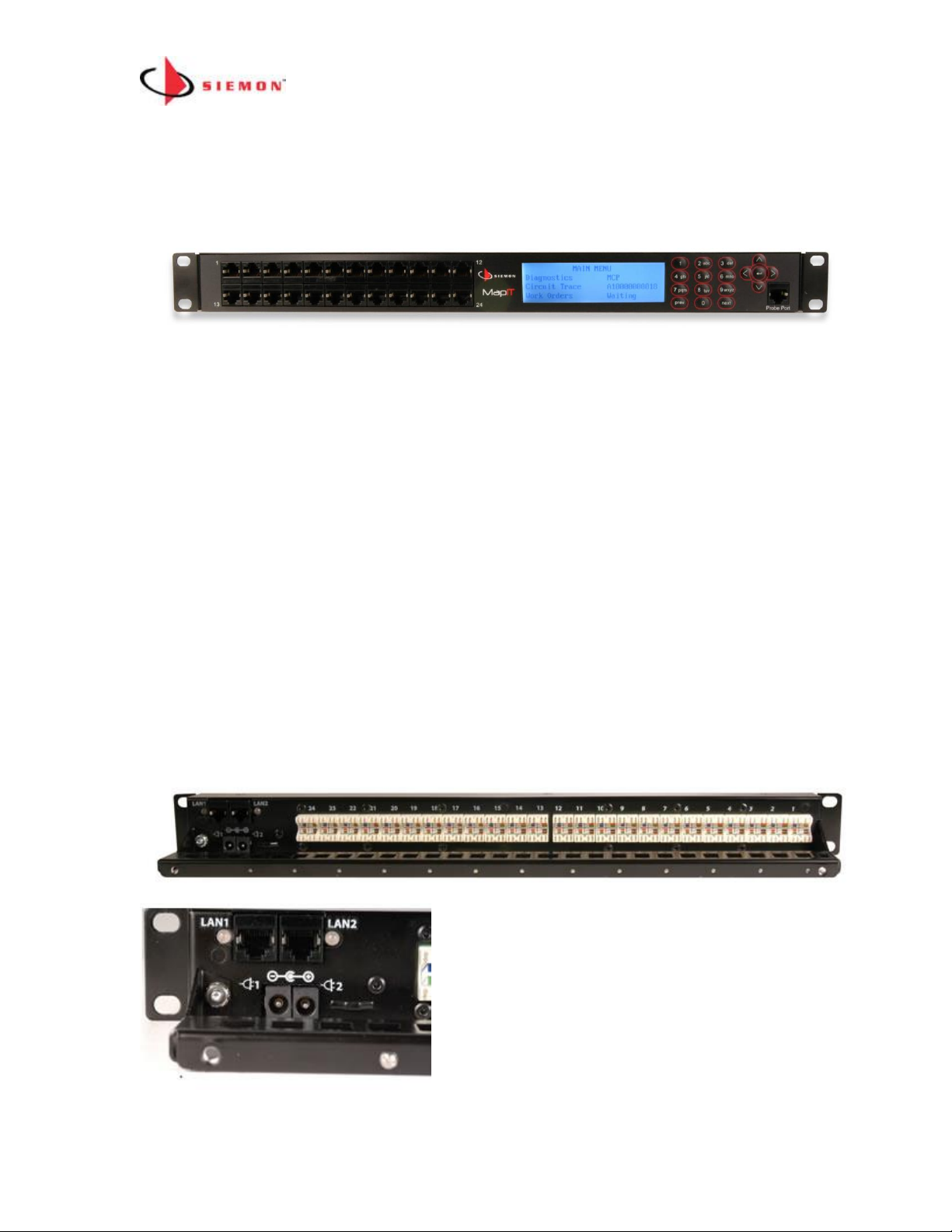
Master Control Panel (MCP)
The MCP is the interface between the EagleEye software and all the Smart
Panels/Enclosures in the Patch Zone. The MCP has two Ethernet ports on the rear of
the unit for connecting to the TCP/IP network. It has 24 ports to connect either directly
to Smart Patch Panels/Fiber Enclosures (SPP/SFE) or to Distribution Control Panels
(DCP).
MCP Dimensions
Component
Width
Height
Depth
MCP
483 mm
19 inches
45 mm
1.75 in
170 mm
7.0 in
Supplied Components
- MCP
- 24 S310 stuffer caps
- Sensor pen
- Rear cable manager & cable ties
- DC power supply
- Installation instructions
Page 8
MapIT G2 Hardware Installation Training Manual Confidential – June 2014
8
The Front of the MapIT G2 Master Control Panel
1. 24 RJ45 I/O Control Bus Outlets – For connections to lower level components
(either directly to SPPs/SFPs or DCPs). Use either the RJ45s or the S310s (on
rear of panel). DO NOT connect both the RJ45 and S310 of a single port
simultaneously.
2. LCD - 4 Line LCD used to view the MCP Menu
3. Alphanumeric Keypad - Use to input information into the MCP
4. Scroll and Enter Buttons - Used to navigate the MCP menu. The Enter button is in
the center.
5. Sensor Pen RJ45 Port - The pen is used for system diagnostics, circuit trace,
mapping and more.
The Rear of the MapIT G2 MCP
Page 9

MapIT G2 Hardware Installation Training Manual Confidential – June 2014
9
1. Twenty Four S310 I/O Bus Connections – For connections to lower level
components (either directly to SPPs/SFPs or to DCPs). Use either S310 connections
on the rear of MCP or the RJ45 ports on the front. DO NOT connect both the RJ45 and
the S310 of a single port simultaneously. If the RJ45 ports are used, Siemon
recommends putting the supplied S310 stuffer caps on the S310 ports on the rear of
the panel. If S310s are used, use the Siemon RJ45 port blockers (p/n LL-05, sold
separately) to prevent access to the RJ45 ports on the front of the MCP.
2. Twelve Ground Termination Points – terminate the drain wire of the cat 5e Control
Bus Cables on these (two drain wires per ground termination point)
3. Two Ethernet RJ45s – The MCP has two 10BASE-T Ethernet ports. Both ports can
be connected to the network for a redundant connection, however only one connection
is operational at a time. If both Ethernet ports are connected, the MCP will attempt to
connect to the network on port #1. If successful it will establish the connection and will
not attempt to connect on port #2. If not successful on port #1, it will attempt to
connect on port #2. The same logic will apply in the event a connection is lost. The
MCP will continue to alternately attempt connections on both ports until a connection is
established. Connect the Ethernet port(s) to the TCP/IP network via RJ45 Patch
Cables (T568A or B wired, Cat 5e Shielded or higher).
4. Two Ethernet Status LEDs – There are LEDs on either side of the Ethernet RJ45s.
When the LED is not lit there is no connection. When an LED is green it indicates the
port has an active Ethernet connection
5. Two Power Connections – The MCP features two ports for redundant power. The
MCP is sold with one power supply. If redundant power is required, purchase a second
power supply (P/N M-PS). Use of a non-Siemon power supply will void the product
warranty and may damage the unit. Connect the power supply(s) to the power port(s).
Secure the power supply cable(s) to the rear manager of the MCP with a cable tie.
6. Rear Manager – A rear manager is provided to secure Control Bus cables (if the
S310 termination style is used). Secure cables with cable ties (supplied) or Velcro
(optional) to the rear manager.
8. Panel Grounding – A ground lug is provided on the rear of the MCP to ground it to
the rack or telecommunications ground. The MCP must be properly grounded for the
system to function properly.
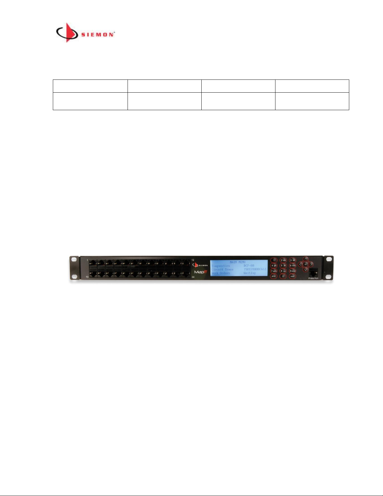
Distribution Control Panel (DCP)
The DCP is used to create larger Patch Zones. MCP can support up to 2880 ports in a
single Patch Zone when used as a standalone device connected directly to
SPPs/SFEs. DCPs can be used to increase the size of the Patch Zone up to 65,000
ports (more details on Patch Zone design guidelines below). You will notice that the
Page 10
MapIT G2 Hardware Installation Training Manual Confidential – June 2014
10
DCP is almost exactly the same as the MCP with two key exceptions – 1) it does not
have Ethernet ports and 2) it has an S110 and RJ45 for connection to the MCP.
Distribution Control Panel Dimensions
Component
Width
Height
Depth
DCP
483 mm
19 inches
45 mm
1.75 in
170 mm
7.0 in
Supplied Components
- DCP
- 24 S310 stuffer caps
- Sensor pen
- Rear cable manager & cable ties
- DC power supply
- Installation instructions
The Front of the Distribution Control Panel (DCP)
1. 24 RJ45 I/O Control Bus – For connections to SPP/SFEs. Use either these RJ45s
or the S310s (on rear of panel). DO NOT connect both the RJ45 and S310 of a
single port simultaneously. If the RJ45s are used, Siemon recommends putting the
supplied S310 stuffer caps on the S310 ports on the rear of the panel. If S310s are
used, use the Siemon RJ45 port blockers (p/n LL-05, sold separately). Always use
T568A wiring scheme for all cables connected to these ports.
2. LCD – 4 Line LCD used to view the DCP menu
3. Alphanumeric Keypad – Use to input information to the Distribution Panel
4. Scroll and Enter Buttons – Used to navigate the DCP menus and input data
5. Sensor Pen Port – Insert supplied probe pen here. Pen can be used for system
diagnostics, circuit trace, mapping and more
Page 11
MapIT G2 Hardware Installation Training Manual Confidential – June 2014
11
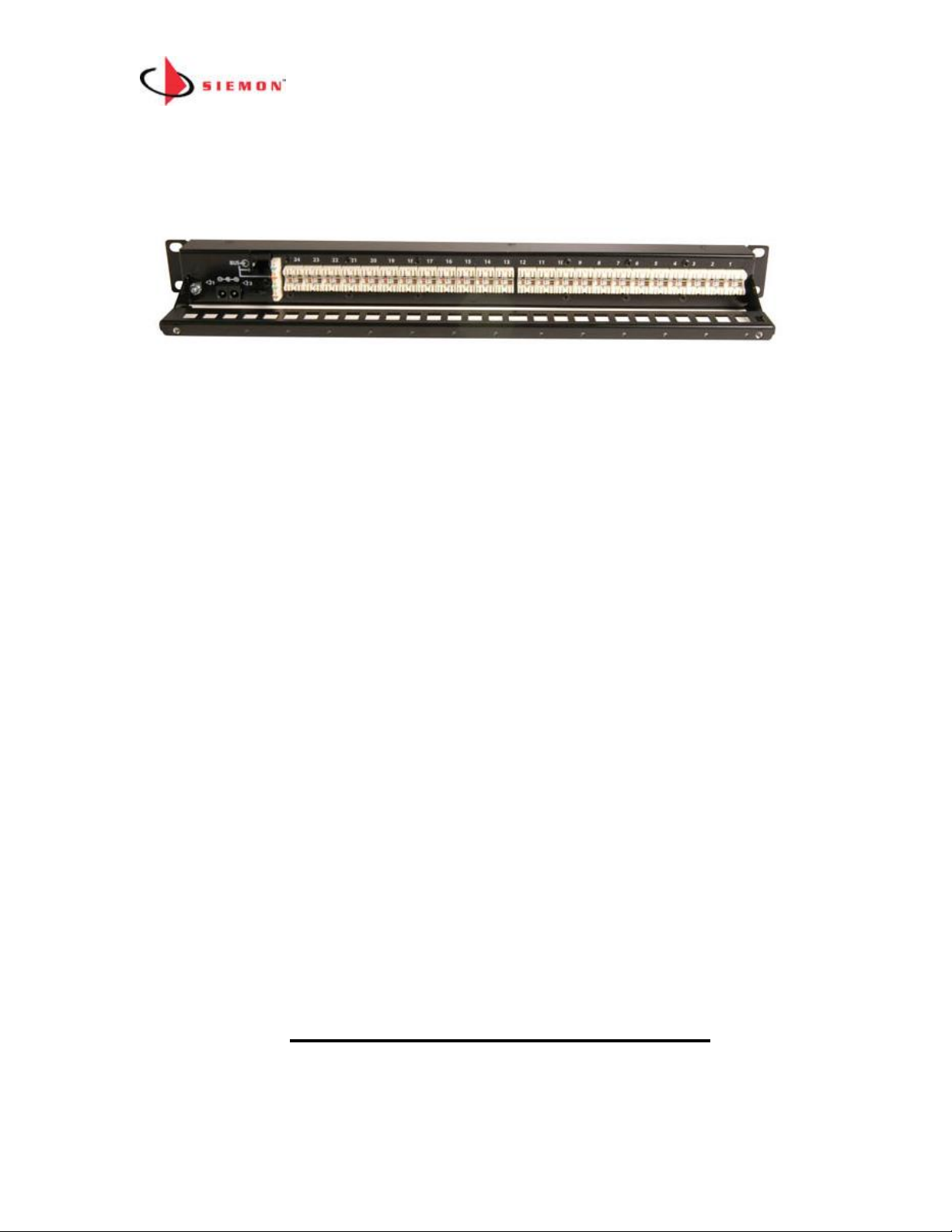
The Rear of the MapIT G2 Distribution Control Panel
1. Twenty Four S310 I/O Bus Cable Connections – For connections to SPPs/SFEs,
Terminate the Control Bus Cable to the S3110s using T568A wiring scheme. Use
either these RJ45s or the S310s (on rear of panel) connections. DO NOT connect
both the RJ45 and S310 of a single port simultaneously. If the RJ45s are used,
Siemon recommends putting the supplied S310 stuffer caps on the S310 ports on
the rear of the panel. If S310s are used, use the Siemon RJ45 port blockers (p/n
LL-05, sold separately).
2. Twelve Ground Termination Points – terminate the drain wire of the cat 5e Control
Bus Cables on these (two drain wires per ground termination point)
3. RJ45 & S110 – Terminate the cable coming from the MCP to either of these ports.
Use cat 5e solid, shielded cable. Terminate using T568A wiring scheme
4. Two Power Connections – The DCP features two ports for redundant power. The
DCP is sold with one power supply. If redundant power is required, purchase a second
power supply (M-PS). Use of a non-Siemon power supply will void the product
warranty and may damage the unit. Connect the power supply(s) to the power port(s).
Secure the power supply cable(s) to the rear manager of the DCP with a cable tie.
5. Rear Manager – A rear manager is provided to secure Control Bus Cables (if the
S310 termination style is used). Secure cables with cable ties or Velcro to the
manager.
6. Panel Grounding – A ground lug is provided on the rear of the DCP to ground it to
the rack or telecommunications ground. The DCP must be grounded for the system to
function properly
MCP and DCP Power Requirements
• One supplied, additional may be purchased separately for redundant power (p/n
M-PS)
Page 12

MapIT G2 Hardware Installation Training Manual Confidential – June 2014
12
• Input 100-240v
• 50-60Hz, 0.6A
• 6v DV, 3.3 Amp
• Use two per MCP or DCP if redundant power is desired
• Use of a non-Siemon power supply will void the system warranty
• Power supply comes with adapters for US, UK, Australia, Europe and China
• SPPs and SFEs do not have their own power supplies. Power is provided to
them via the Control Bus Cable
Smart Patch Panels (SPP/SPPA/TPPA)
MapIT G2 smart patch panels and fiber enclosures SFPs have capabilities beyond any
other product in our industry today. The ability to track connections is built into the
panel. This reduces rack space required for monitoring equipment by up to 89%. The
system also uses much less power than competing systems. Finally, it does not
require proprietary cables to devices in the system. The use of standard 5e solid
shielded cable reduces cost and speeds installation time. Also, fewer cables are used
to connect items in the system, so less space is required for pathways. The Smart
Panels/Enclosures also feature two LEDs and an LCD which provide a local user
interface, which can save significant time during diagnostics and work order
provisioning.
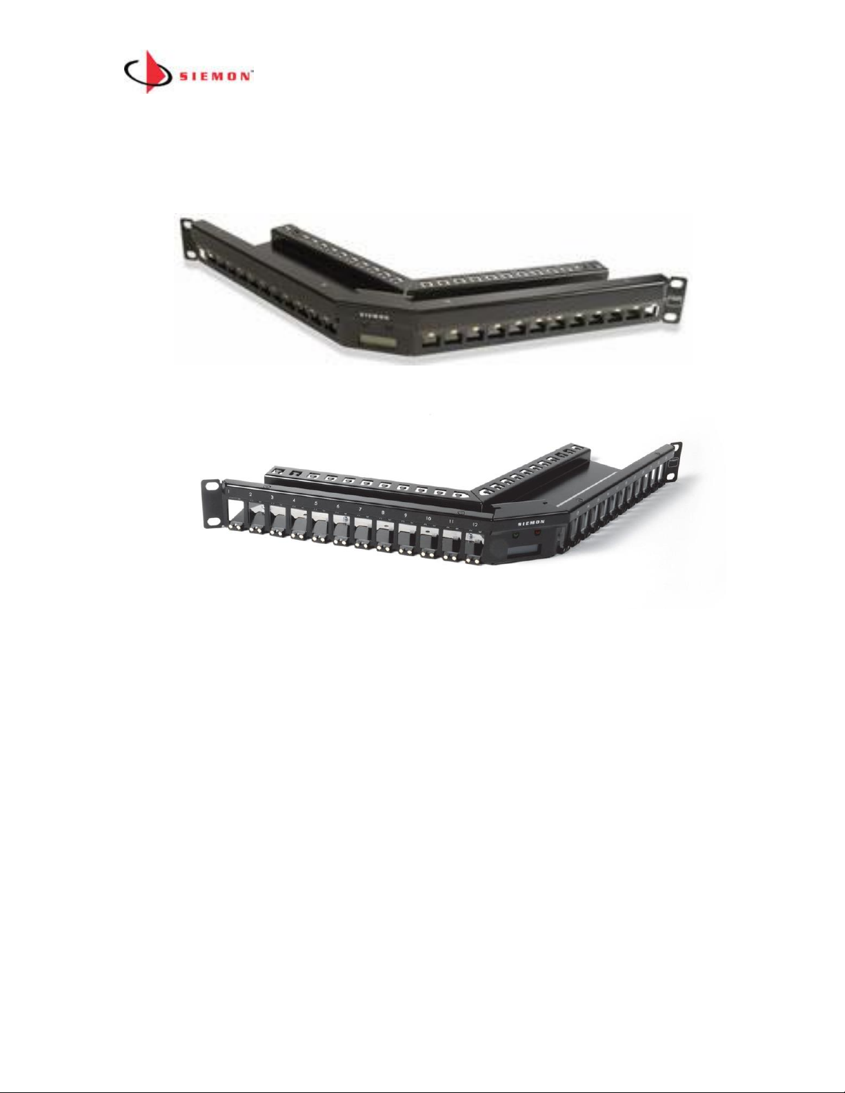
The SPP (flat smart patch panel) and SPPA (angled smart patch panel) are typically
sold empty and accept Siemon keystone ZMAX outlets. The TPPA (angled TERA
smart panel) accepts Siemon TERA outlets.
Smart Panel Dimensions
Component
Width
Height
Depth
SPP (Flat)
483 mm
19 in
45 mm
1.75 in
170 mm
7.0 in
SPPA (Angled)
483 mm
19 in
45 mm
1.75 in
225 mm
8.86 in
TPPA (TERA
Angled)
483 mm
19 in
45 mm
1.75 in
225 mm
8.86 in
The Front of the MapIT G2 Smart Patch Panels
Flat Panel
Page 13
MapIT G2 Hardware Installation Training Manual Confidential – June 2014
13
Angled Panel
TERA Panel
1. Panel Design - 24 ports, 1U modular design accepts UTP or F/UTP connectors
2. LCD – Displays Patch Cable trace information, port and panel diagnostics and work
order instructions (future capability). Display is backlit for best viewing in a variety
of lighting conditions
3. LEDs – One green and one red LED for guidance on work orders instructions
4. Probe Pads – Gold pad above each port. This is the landing area for the pogo pin
built into MapIT G2 Patch Cables. This pad can also be used for circuit traces and
diagnostics via the Pen Probe
5. Port Labeling Space – Space provided for labeling of ports
6. Mounting – mounts on standard 19” racks and cabinets
7. Power – The Smart Panel gets its power from its connection to the MCP or DCP
Page 14
MapIT G2 Hardware Installation Training Manual Confidential – June 2014
14
When a MapIT G2 Patch Cable is inserted or removed from a port, the Smart Panel
discovers the connection and communicates the port ID information to the MCP via the
Control Bus cable. The MCP relays the information to the EEC software over a TCP/IP
connection. Any changes in connectivity are immediately updated in the EEC
database. This provides network administrators with vital up-to-the minute information
about the status of their network, from the hardware layer and up… anytime,
anywhere.
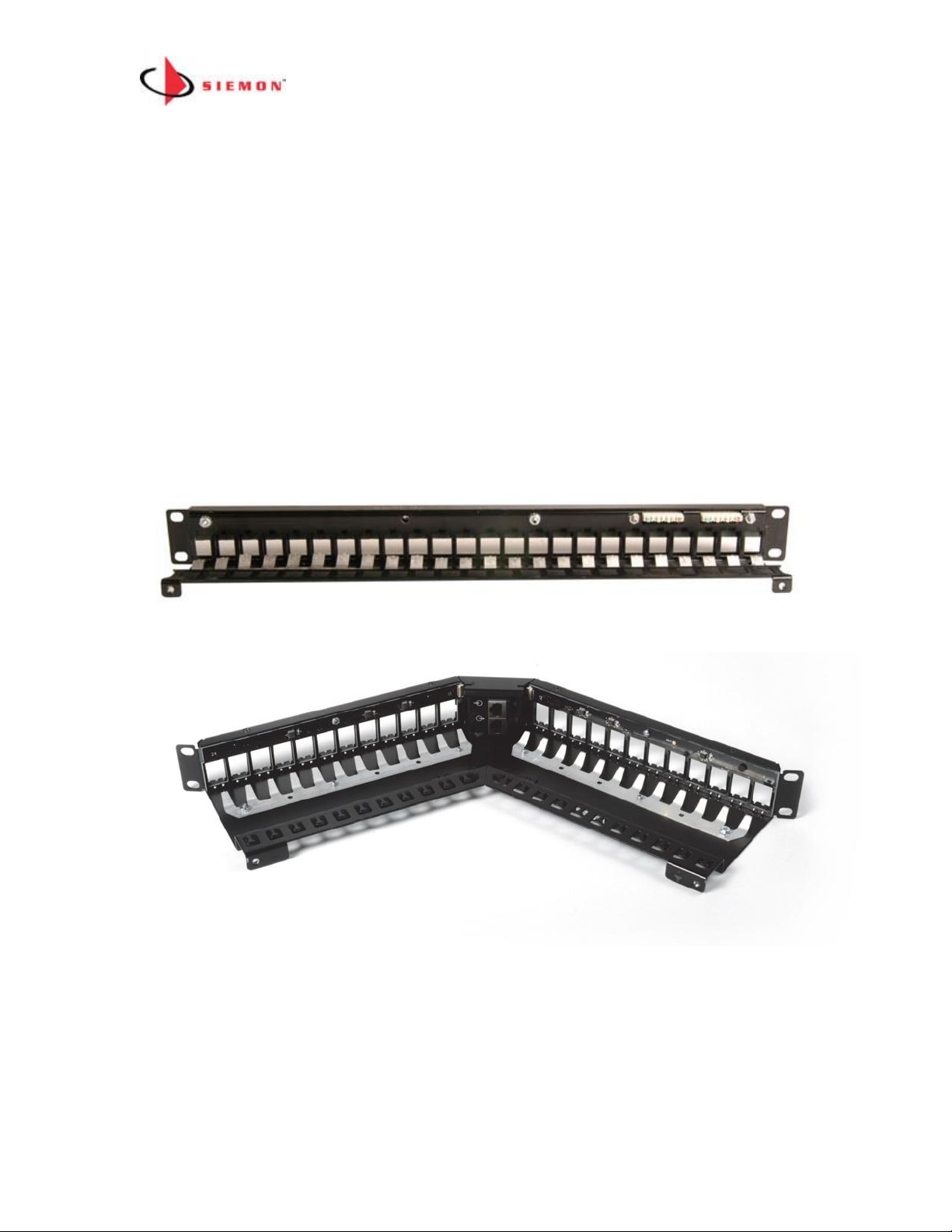
The Rear of the MapIT G2 SPP
Flat Panel
Angled Panel/TERA Panel
Rear View of the MapIT G2 Smart Patch Panel
1. Flat Panels – have two S110 Control Bus Cable Connections. Terminate the
control bus cables routed from the MCP or DCP to the IN port. Daisy chain Control
Bus Cables from the OUT port of one panel to the IN port of the next panel
(adjacent or below). Up to five SPPs can be daisy chained on a single connection.
A redundant daisy chain path can be created by connecting the OUT ports of the
last panels of two separate daisy chains. Important Note: If the redundant daisy
Page 15

MapIT G2 Hardware Installation Training Manual Confidential – June 2014
15
chain is used, the two Daisy chained links must be served from the same MCP or
DCP. Do not attempt to span the redundant link between different MCPs or DCPs.
2. Angled Panels – have two RJ45 Control Bus Cable Connections. The top RJ45
is the IN port. The bottom is the OUT port. Connect the IN port to a port on the
MCP, connect the OUT port to the IN port of the next SPP in the daisy chain (if
applicable). A maximum of five panels can be connected in each daisy chain. Important
Note: If the redundant daisy chain is used, the two Daisy chained links must be
served from the same MCP or DCP. Do not attempt to span the redundant link
between different MCPs or DCPs.
3. Flat Panel Ground Termination Points – terminate the drain wire of the cat 5e
bus/daisy chain cables on these (one drain wire per connector). Not required for
angled panels
4. Rear Manager – A rear manager is integrated into the panel. Secure cables with
Velcro or cable ties securely to the manager.
4. Panel Grounding – A ground lug is provided on the rear of the SPP for grounding to
the rack or telecommunications ground (TGBB). The Smart Panel must be properly
grounded for the system to function properly
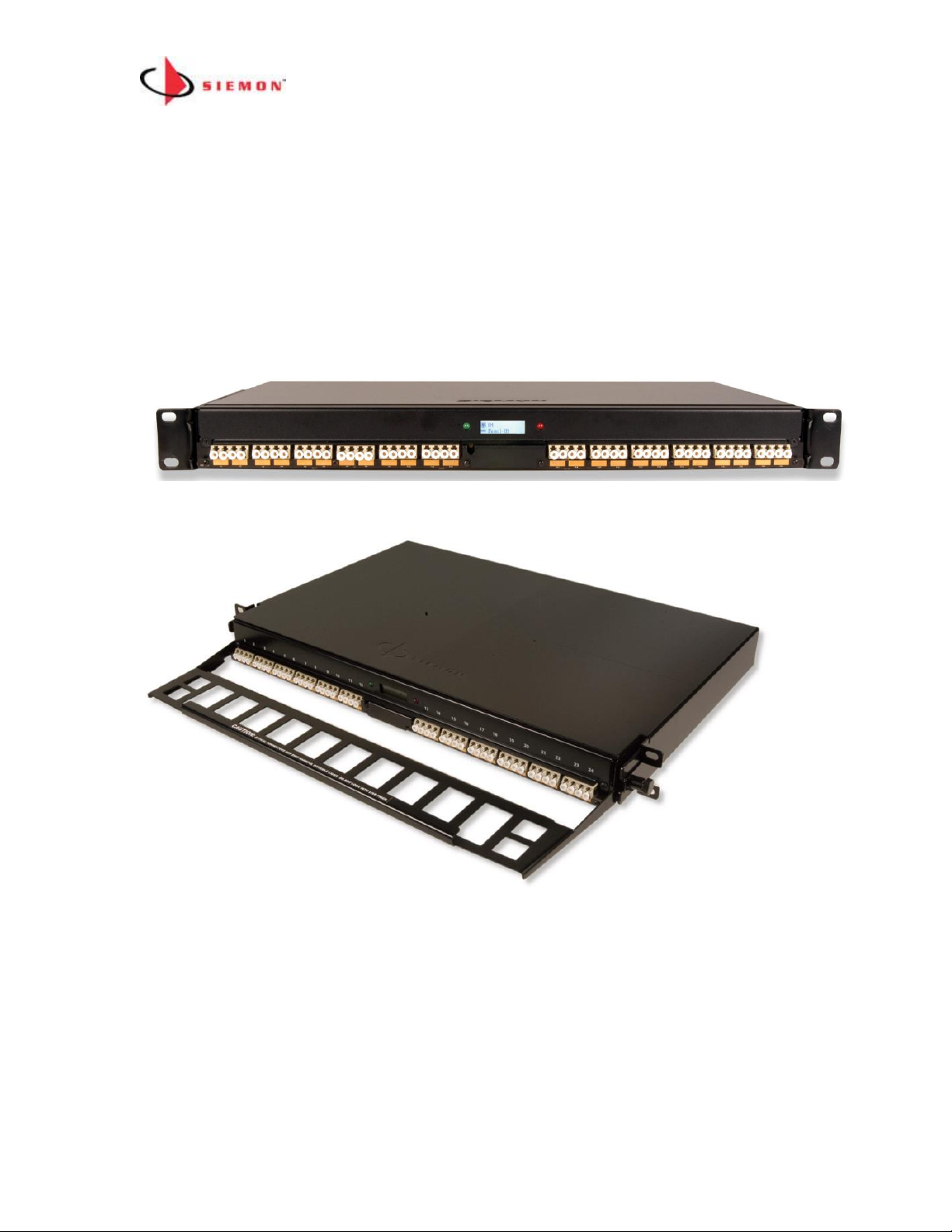
Smart Fiber Enclosures (SFE & SMTP)
The Front of the MapIT G2 Smart Fiber Enclosure (SFE & SMTP)
1. Panel Design – 48 LC fiber (24 managed duplex connections) 1U, compatible with
either multimode or single mode fiber
2. LCD – Displays Patch Cable trace information, port and panel diagnostics and work
order instructions (future capability). Display is backlit for best viewing in a variety
of lighting conditions
3. LEDs – Provide guidance for work order instructions
4. Probe Pads – Used for diagnostics and is the landing area for the pogo pin built into
MapIT G2 Fiber Jumpers
5. Port Labeling Space – Space provided for labeling of ports and panel
6. Mounting – mounts on standard 19” racks and cabinets
Page 16
MapIT G2 Hardware Installation Training Manual Confidential – June 2014
16
7. Power – The Smart Enclosure gets its power from its connection to the MCP or DCP
via the Control Bus Cable
8. Integrated Front Cable Manager (SMTP version only) – Provide management of
LC fiber jumpers connected to the front of the SMPT enclosure
Front view of the MapIT G2 Smart Fiber Enclosures
SFE
SMTP
Rear of SFE
1. 2 RJ45 Control Bus Cable Connections –Connect the Control Bus
cable routed from the MCP or DCP to the IN port on the inside of the
SFE. Daisy chain control bus cables from the OUT port of the SFE to the
IN port of the SFE adjacent or below. Up to 5 SFEs can be daisy chained
together. A redundant daisy chain path can be created by connecting the
OUT ports of the last panels of two separate daisy chains. Important
Page 17
MapIT G2 Hardware Installation Training Manual Confidential – June 2014
17
Note: If the redundant daisy chain is used, the two daisy chained links
must be served from the same MCP or DCP. Do not attempt to span the
redundant link between different MCPs or DCPs.
2. Enclosure Grounding – A ground lug is provided on the rear of the SFE
to ground it to the rack or telecommunications ground. The SFE must be
properly grounded for the system to function properly
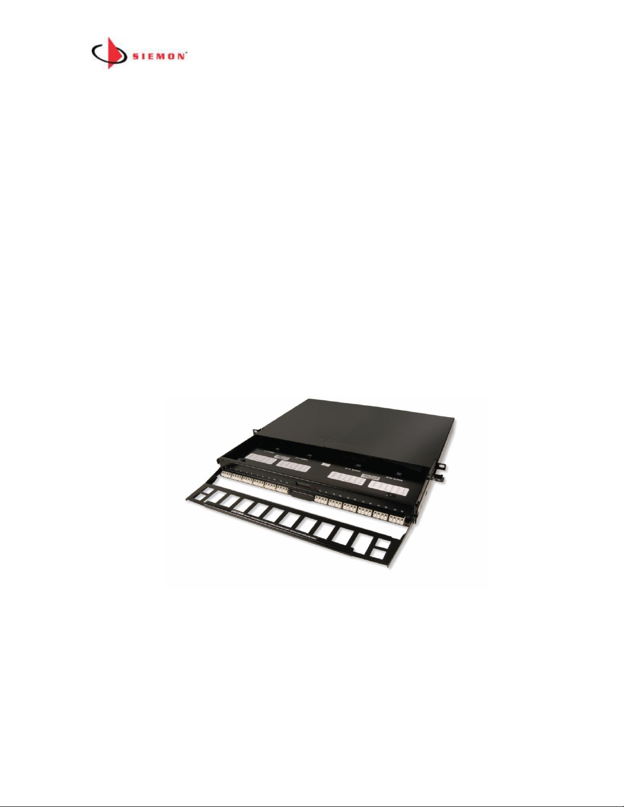
3. SFE vs. SMTP – The SFE is use for direct termination LC, fusion splicing
and LC trunks. The SMTP is prepopulated with LC to MTP cassettes.
Use the SMTP when using MTP fiber trunks
Expanded View of SMTP Enclosure
Page 18
MapIT G2 Hardware Installation Training Manual Confidential – June 2014
18
Module 2: System Design and Installation
System Design Guidelines
The center of the design is the Master Control Panel (MCP). A Master Control Panel
can support a single patch zone. A patch zone is a collection of SPPs and SFEs that
can be connected by patching between them using MapIT G2 Patch Cables or Fiber
Jumpers. This is typically a single telecommunications room.
Patch zones with less than 2880 monitored ports (120 panels x 24 ports each) ports)
can be served by a single MCP. To create larger Patch Zones we add one or more
DCPs to the system.
Therefore, to design a system, patch zones must be clearly planned and installed with
an MCP and lower level components.
Note: Detection of SPP/SFP port connectivity is only possible between panels
connected to the same MapIT G2 MCP.
How to Configure a Patch Zone of less than 120 Patch Panels
Each MCP can support up to 120 patch panels/fiber enclosures. If you are installing a
patch zone with less than 120 patch panels and do not plan on any expansion beyond
this number, you can use the following topology:
Page 19

MapIT G2 Hardware Installation Training Manual Confidential – June 2014
19
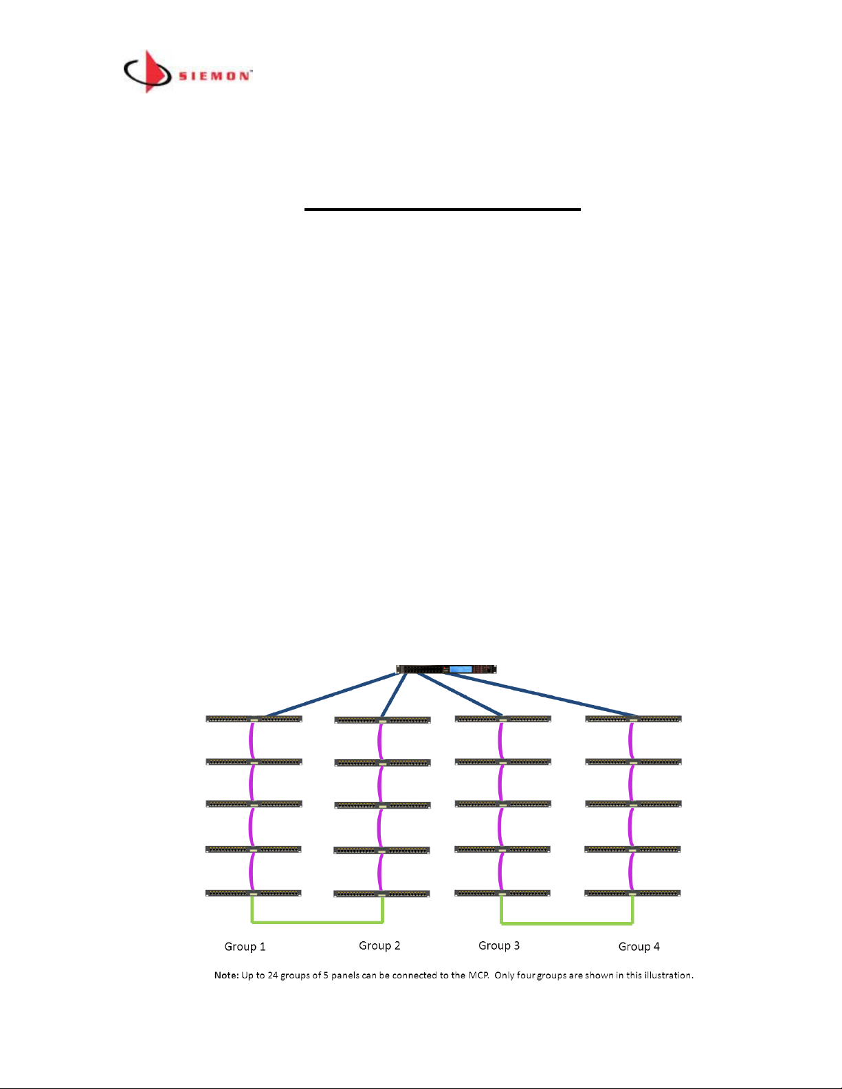
Small Patch Zone Topology Rules
1. Use one MCP (supports from 1 up to 120 panels/enclosures (5x24))
2. Each of the 24 Control Bus Cable ports on the MCP can have up to 5
panels/enclosures connected to it via a daisy chain
3. Maximum length a MapIT G2 Patch Cable/Fiber Jumper can be 75’ (24m)
4. Panels do not have to be in the same rack/cabinet as the MCP
5. A redundant daisy chain can be used as an option for greater system reliability.
In the example above the OUT port of the last panel in Group 1 is connected via
Control Bus Cable to the OUT port of the last panel in Group 2. In the event that
the chain is broken at any point, the panels in the daisy chain will still track
connections and communicate with the MCP. The system can also provide an
alert in the event that the redundant daisy chain is broken. The fault should be
repaired at the earliest possible convenience to ensure greatest system
reliability
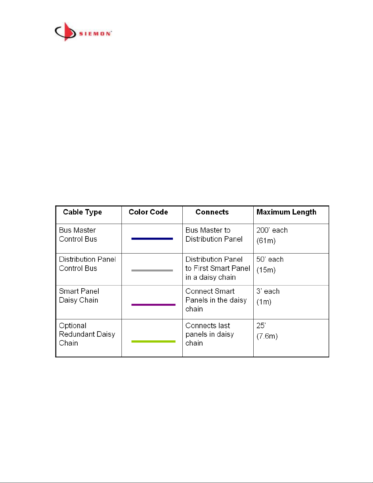
Control Bus Cable Length Limitations (per Small Patch Zone Diagram shown
above)
(See the Control Bus Installation section below)
25’ per cable
(7.6m)
Connects last Panels
in a Daisy Chain
Optional
Redundant Path
Connection
3’ per cable
(1m)
Panels in the Daisy
Chain
Smart Panel
Daisy Chain
50’ per cable
(15m)
MCP to First Smart
Panel in a Daisy
Chain
MCP Control Bus
Maximum Length
Connects
Color Code
Cable Type
Page 20
MapIT G2 Hardware Installation Training Manual Confidential – June 2014
20
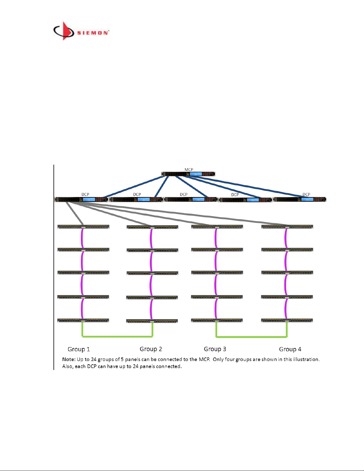
How to Configure Large Patch Zones (Greater than 120 Panels/Enclosures)
Use a combination of one MCP and up to 24 DCPs to create a Patch Zone with up to
65,000 ports. The topology for this type of Patch Zone is shown below (Only DCP #1
and connections for three of its ports are shown for clarity).
Large Patch Zone Topology Rules
Page 21
MapIT G2 Hardware Installation Training Manual Confidential – June 2014
21
1. Use one MCP and up to 24 DCPs for patch zones with 121+
panels/enclosures
2. Each port on the MCP can have one DCP connected to it
3. SPPs and SFEs can be daisy chained to DCP ports (up to 5 per DCP port).
4. SPPs and SFEs can also be connected to unused MCP ports
5. A redundant daisy chain can be created by connecting the last panels in two
daisy chains for greater system reliability. In the above example the last
panel in Group 1 is connected to the last panel in Group 2. In the event that
the chain is broken at any point, the system will still work and it will provide
an alert of the fault. The fault should be fixed at the earliest possible
convenience.
6. If you are using a redundant daisy chain both groups of panels must be
connected to the same MCP or DCP. You cannot span the redundant link
between DCPs or MCP to DCP
7. Maximum length of a MapIT G2 Patch can be 75’ (25m)
Control Bus Cable Length Limitations (for Large Patch Zone Diagram shown
above)
(See the Control Bus Installation section below)
Page 22

MapIT G2 Hardware Installation Training Manual Confidential – June 2014
22
MapIT G2 System Configuration Examples
Example 1:
In this small Patch Zone we have 50 panels connected to the MCP. Each group of 5
panels is connected to a single port on the MCP. In this case the 50 panels would
occupy 10 of the 24 available ports in the MCP. Note that a single MCP can connect to
panels in adjacent racks as well as the same rack as the MCP.
Page 23

MapIT G2 Hardware Installation Training Manual Confidential – June 2014
23
Example 2:
The number of panels and port count is exactly the same as in example #1 above.
However, in this example DCPs are used in four racks and an MCP is used in one
rack. This configuration can be used if better visibility of LCD screens is desired. The
MCP is connected to each of the DCPs. The SPPs/SFEs on the same rack as the
MCP can be connected directly to the MCP if desired. Panels can be daisy chained as
describe above, however since there are very few panels in this example, each of the
10 panels in each rack can be connected directly to individual ports on the MCP and
DCPs.
Page 24

MapIT G2 Hardware Installation Training Manual Confidential – June 2014
24
Example 3:
In the example below each rack has 40 24-port Patch panels. In this scenario each
DCP (in light blue) can support 3 racks (a total of 120 panels). There are a total of 18
racks (total of 66 panels). You would need 6 DCPs to accommodate all the panels in
this patch zone. The MCP can be located anywhere in this patch zone as long as any
individual cable connecting it to a DCP is no longer than 200’. The MCP could support
up to 18 more DCPs, so there is plenty of room for expansion in this example.
MapIT G2 Patch Zone Sizing and Capacity Planning
When creating a design from your site survey, there are many decisions to be made
based on customer specifications and needs. The type and number of units used can
vary depending upon the following criteria:
• Real-estate space available in the rack or cabinet
• The number of panels to be monitored initially in each patch zone
• The expected port growth in each patch zone
• The maximum length of MapIT G2 Control Bus cables and MapIT G2 Patch
Cables
Page 25

MapIT G2 Hardware Installation Training Manual Confidential – June 2014
25
MapIT G2 Site Survey
This section provides the recommended procedure and forms to complete a Site
Survey for a new MapIT G2 installation.
The MapIT G2 Site Survey is an information-gathering activity used to survey the
client’s existing network infrastructure, to determine the necessary MapIT G2
components for completing a successful installation.
The survey forms will help outline the proper placement of MapIT G2 components
based on the number, distribution and location of MapIT G2 Panels to be monitored.
The survey forms include a general summary of the project, a MapIT G2 Patch
Panel/Equipment Profile form, a Rack Configuration form and a general Bill of
Materials (Cables) form.
Survey Information
The information found at the site survey is the foundation upon which all future design
plans and the final design solution will be based. If additional information is needed,
the site administrator should be contacted to gather this information before proceeding.
At a minimum, the following should be obtained:
Physical layout of the site (Floor Plans, Map, etc.)
Type of MapIT G2 equipment to be used
Placement of MapIT G2 MCP and (if required) DCPs within each Patch Zone
MapIT G2 Control Bus cables and maximum MapIT G2 Patch Cable lengths
Defining the Client Needs
The demands to tailor different systems and configurations will vary dramatically from
client to client. For this reason, it is essential to determine the specific needs and
requirements of each client to create a specific design to meet their
needs/expectations. Defining client needs encompasses all aspects of the design and
project management processes. Below is a suggested list of items that should be
defined at the site survey:
1. Is there enough room on the rack(s) for MapIT G2 MCP and (if required) DCPs?
2. Does the client provide rack space for the MCP and DCPs near the SPPs/SFEs
or will they need to be placed away from the rack? If so, how far away will they be
installed?
Page 26

MapIT G2 Hardware Installation Training Manual Confidential – June 2014
26
3. What is to be tracked? Voice, Data, or both?
4. It is important to know the client’s operating system and how the network
operates to determine whether the system meets specifications and to determine
what part of the network the client is going to want MapIT G2 enabled and
monitored by EEC software. Many clients focus on enabling essential equipment
that is necessary to be up and running 99.9% of the time.
5. Determining the client’s network layout will also allow us to accurately gauge the
Patch Zone configuration.
6. System documentation is important in any system. Knowing where all the cables
begin and where they terminate is essential in creating an effective end-to-end
system. With the client, determine whether the existing documentation is
satisfactory or whether the cables will need to be toned out (for an existing
installation).
NOTE: A digital camera is useful to document existing conditions for future
reference.
Rack/Cabinet Configuration
Rack/Cabinet Configuration identifies the location of the existing equipment as well as
placement of the MapIT G2 MCP/DCPs in the racks. This allows the installer to
visualize the configuration of the installation and provides equipment information
including; floors, TRs, racks, Patch Zones, etc. Within the depicted racks, the
Equipment IDs are displayed. Distances between racks and associated floors should
be indicated. Control Bus Cable requirements are identified and a Notes section for
additional information is provided.
Page 27

MapIT G2 Hardware Installation Training Manual Confidential – June 2014
27
Example #1
Page 28

MapIT G2 Hardware Installation Training Manual Confidential – June 2014
28
Site and Requirement Survey Forms
Siemon will provide the following documents to collect data required to configure
the MCPs and build the database. These must be completed and returned to Siemon
in order to build the EEC database.
- MCP Network Settings and Locations
- Database Build
- Discovery Questionnaire
- Email Server and Events
- Floor Graphics
- Rack/Cabinet/Faceplate Locations
- Rack Elevations
MapIT G2 Hardware Installation
The following steps for the hardware installation of the MapIT G2 Components can be
used as a basic checklist to insure that all of the steps have been accounted for during
installation.
Step 1.
Mount the MapIT G2 MCP, DCPs (if applicable) and SPPs/SFEs in the equipment
rack(s) as specified on the drawings. These components may be stacked above or
below other components. Since all MapIT G2components generate virtually no heat,
there is no need for additional spacing for cooling. Use all of the installation hardware
supplied with each unit.
Step 2.
Make sure that all components are powered down before beginning terminations.
Disconnect all power supplies from the panels and the electric power outlets.
Step 3.
Connect the Control Bus Cables from the MCP to the DCPs (if applicable) or
SPPs/SFEs using the proper cable and termination practices. Connect the daisy chain
Control Bus cables between the Patch panels. If desired, connect the last panel in
each daisy chain to another panel to create a redundant daisy chain. The redundant
cable connection must connect 2 daisy chains on the same MCP or DCP. Do not span
across MCPs and/or DCPs. Siemon recommends that the daisy chained ports be
connected between panels on adjacent ports on a MCP or DCP (for example, create a
Page 29

MapIT G2 Hardware Installation Training Manual Confidential – June 2014
29
redundant connection between the panels connected from port 1 and port 2 on an
MCP or DCP).
Step 4.
Connect a ground wire from the back of all components (MCP, DCPs, SPPs, SFEs) to
the telecommunications ground. Proper grounding is critical to proper functioning of
the MapIT G2 system
Step 5.
Install the provided power supply cords in each MCP and DCP (if used), then plug
each of them into the electrical power outlets.
Step 6.
Check the power connections: There are two methods of doing this:
1. When power is connected to the MCP and DCPs, power will be supplied to
the SPPs/SFEs in the Patch Zone. If firmware has not be loaded on the
MCP, the LCDs on the SPP/SFEs will display UNLICENSED. This is an
indicator that the panels have power and are communicating with the MCP.
If firmware is loaded in the MCP, then the starting assigned port number will
be displayed on the SPP. If the LCD on a panel is blank, check the power
connections to that panel.
2. You can also look in the MCP or DCP menu to view connections. See the
Diagnostics section below for more information.
Step 7.
Run Diagnostics for all components in the system to ensure all components are
functioning properly (see Diagnostics instructions below).
Step 8.
Terminate all of the horizontal cables that are to be monitored.
Install the terminated connectors in the SPPs and/or SFEs
Step 9.
Install the MapIT G2 Patch Cables and/or Fiber Jumpers as required.
V01.09
Unlicensed
Page 30

MapIT G2 Hardware Installation Training Manual Confidential – June 2014
30
Installing MapIT G2 Control Bus Cables
The Control Bus Cables provide connectivity to the MCP, DCPs, SPPs and SFEs
installed in the system. The installation of the cabling should follow the installation
practices found in the Siemon Cabling System Training Manual.
Control Bus Cable Construction:
• Category 5e, 24 AWG, shielded, solid. Use Siemon Premium 5e F/UTP. Use of
UTP or stranded shielded cable is not permitted. All terminations (S110, S310
and RJ45) should be done using the T568A wiring scheme
• If double-ended shielded Patch Cable cables are used they must be constructed
with Siemon Premium 5e F/UTP 24 AWG, shielded, solid cable and PS-8-8
plugs. Cables must be wired using T586A wiring scheme. Stranded cable is
not acceptable.
• If single-ended Patch Cable cables are used, they must be wired T568A and
use Siemon Premium Category 5e, 24 AWG, shielded, solid cable
Rule for Termination of Control Bus Cable in a Small Patch Zone with a Single
MCP:
If using the S310 and S110 blocks to terminate control bus cables…
• Only use the S310 on the rear of the MCP. Do not use the RJ45s on the front of
the MCP. Use optional RJ45 port blockers (LL-05) to prevent use of RJ45s.
• Terminate cable to S310 blocks on the MCP using T568A wiring scheme.
Connect the drain wires to the ground termination points. Maximum length of
each cable is 50’ when connected to the first SPP/SFE as a daisy chain
• Terminate the Control Bus Cable coming from the MCP to the “IN” S110 block
on the first SPP in the daisy chain. Use T568A wiring scheme. Connect the
drain wire to the ground termination point on the rear of the SPP
• Terminate the SPP Daisy Chain cable to the OUT S110 block of the first SPP to
the IN S110 port on the next SPP/SFE in the daisy chain. Repeat for up to 5
Page 31

MapIT G2 Hardware Installation Training Manual Confidential – June 2014
31
panels in a single daisy chain. The maximum length of each SPP/SFE daisy
chain segment between panels is 3’ (1m). Terminate the drain wire on the
ground termination points on the rear of the SPP/SFE
• If the redundant daisy chain is desired, connect the “OUT” of each of the last
panels in the daisy chain. Max length of this cable is 25’ (11m). Redundant
daisy chain connections can only be made between panels served by the same
DCP or MCP.
• Another termination option is to terminate the Control Bus Cable using S110 P4
plugs (for connections to SPPs or between SPPs). Leave enough drain wire out
the back of the P4 plug to connect it to the ground termination point.
If using the MCP RJ45s and SPP S110 Blocks to Terminate Control Bus Cables…
• Only use the RJ45s on the front of the MCP. Do not use the S310s on the rear
of the panel. You can use the supplied S310 stuffer caps to cover the unused
S310 to prevent connections to these ports.
• Plug in RJ45 plug end of the Control Bus Cable into RJ45 outlet on the front of
the MCP
• Terminate other end of the Control Bus cable to the “IN” S110 port on the first
Patch panel in the daisy chain. Use T568A wiring scheme. Terminate drain wire
to ground termination point. Maximum cable length is 50’ (14m)
• Terminate cable to “OUT” S110 block of the first panel in the daisy chain.
Terminate the other end of this cable to “IN” S110 block on the second Patch
panel in the daisy chain. The max length of this cable is 3’ (1m). Terminate the
drain wire on the ground termination point
• Continue this daisy chain termination method for remaining panels (max 5
panels per single daisy chain, up to 10 for the redundant daisy chain)
• If the redundant daisy chain is desired, connect the “OUT” S110 blocks of each
of the last panels in the daisy chain. Max length of this cable is 25’ (7.6m)
If using the MCP RJ45s an Angled Panel or Fiber Enclosure RJ45 Bus
Connections
• Use a shielded patch cord to connect the MCP RJ45 port to the IN port of the
panel
• Do not reuse the S310 ports on the back of the MCP
• Daisy chain an additional 4 panels (Connect OUT port from one panel to IN port
on the next panel)
• If the redundant daisy chain is desired, connect the OUT port of the last panel in
a group to the OUT port of the last panel in the next group
Rule for Termination of Control Bus Cable in a Large Patch Zone:
Page 32

MapIT G2 Hardware Installation Training Manual Confidential – June 2014
32
If using the S310 and S110 blocks to terminate control bus cables…
• If using this configuration, only use the S310 on the rear of the MCP and
DCP(s). Do not use the RJ45s on the front. Option RJ45 port blockers (LL-05)
can be purchased to block these ports.
• Terminate cable to S310 blocks on MCP using T568A wiring scheme. Connect
drain wire to ground termination point. Max length of each MCP to DCP Control
Bus Cable is 200’
• Terminate the Control Bus Cables coming from the MCP to the vertical S110
block on the rear of each DCP. Use T568A wiring scheme. Connect drain wires
to ground termination point
• Terminate the DCP Control Bus Cables to the S310 blocks on the rear of the
DCP. Use T568A wiring scheme. Terminate the drain wire to ground
termination point. The maximum length of each DCP Control Bus Cable is 50’.
• Terminate the other end of the DCP Control Bus Cable to the “IN” S110 block on
the first SPP in a daisy chain. Terminate the drain wire to the ground
termination point.
• Terminate the SPP Daisy Chain cable to the “OUT” S110 block of the first panel
in the daisy chain. Terminate the other end of this cable to “IN” S110 block on
the second Patch panel in the daisy chain. Terminate drain wires to ground
termination points. The max length of each SPP Daisy Chain Cable is 3’ (1m).
• Continue this daisy chain termination method for remaining panels (max 5
panels per single daisy chain, up to 10 for the redundant daisy chain).
• If the redundant daisy chain is used, connect the “OUT” S110 blocks of each of
the last panels in the daisy chain. Max length of this cable is 25’
• Redundant daisy chain can only be used for panels served by the same DCP or
connected directly to the same MCP. Do not create redundant daisy chains
between panels served by different DCPs or MCPs.
If using Solid, Shielded Cat 5e Patch Cables to connect MCP to DCP and Singleended Solid, Shielded Cat 5e IC Cables to connect the DCP to SPP…
• Only use the RJ45s on the front of the MCP and DCPs. Do not use the S310s
on the rear of the panels. Use option supplied S310 stuffer caps to prevent
access to S310s on the rear of the panel
• Patch Cables used in the Control Bus may be terminated in the field, however
you must always 1) use approved Siemon components, 2) terminate cables
using T568A wiring and 3) test Cables for continuity prior to installation in the
system
• Plug Patch Cable into RJ45 ports on front of the MCP
• Plug the other end of the Cable into the RJ45 control bus cable port on the rear
of the DCP. The maximum length of this cable is 200’
• Use a single-ended Cable to connect the DCP to the first SPP in a daisy chain.
Plug one end into the RJ45 port on the front of the Distribution panel. The
maximum length of this cable is 50’
Page 33

MapIT G2 Hardware Installation Training Manual Confidential – June 2014
33
• Terminate the open end of the cable to the “IN” port of the first SPP in a daisy
chain. Use T568A wiring scheme. Terminate the drain wire on the ground
termination point
• Terminate cable to “OUT” S110 block of the first SPP in the daisy chain.
Terminate the other end of this cable to “IN” S110 block on the second SPP in
the daisy chain. The max length of this cable is 3’ (1m)
• Continue this daisy chain termination method for remaining panels (max 5
panels per single daisy chain, up to 10 for the redundant daisy chain)
• If the redundant daisy chain is desired, connect the “OUT” S110 blocks of each
of the last panels in the daisy chain. Max length of this cable is 25’
• Redundant daisy chain can only be used for panels served by the same DCP or
connected directly to the same MCP. Do not create redundant daisy chains
between panels served by different DCPs or MCPs
If using the RJ45 Patch Cable cables for Control Bus connections throughout the
system (for Angled, TERA and Fiber Enclosures)…
• If using this configuration, only use the RJ45s on the front of the MCP and
Distribution Panel. Do not use the S310s on the rear of the panels. Siemon
recommends using the supplied S310 stuffer caps to prevent access to the
S310s.
• All RJ45 outlets used in the system are grounded.
• Patch Cables used in the Control Bus may be terminated in the field, however
you must always 1) use approved Siemon components, 2) terminate cables
using T568A wiring and 3) test Cables for continuity prior to installation in the
system
• Plug Patch Cable into RJ45 ports on front of the MCP
• Plug the other end of the Cable into the RJ45 bus cable port on the rear of the
DCP. The maximum length of this cable is 200’
• Use the next cable to connect the DCP to the first SFE in a daisy chain. Plug
one end into an RJ45 port on the front of the DCP. Plug the other end into the
“IN” RJ45 on the first SFE in a daisy chain. The maximum length of this Patch is
50’
• Plug another Patch Cable for the Daisy Chain into the “OUT” port on the first
SFP. Plug the other end into the “IN” port on the next SFE. The maximum
length for this type of Cable is 3’
• Continue this daisy chain termination method for remaining panels (max 5
panels per single daisy chain, up to 10 for the redundant daisy chain)
• If the redundant daisy chain is desired, connect the “OUT” RJ45s of each of the
last enclosures in the daisy chain. Max length of this Patch Cable is 25’
• Redundant daisy chain can only be used for panels served by the same DCP or
connected directly to the same MCP. Do not create redundant daisy chains
between panels served by different DCPs or MCPs
This completes the hardware installation.
Page 34

MapIT G2 Hardware Installation Training Manual Confidential – June 2014
34
Module 4: Navigating the MapIT G2 Menus
Main Menu
Insure that the MCP is properly connected to a power source. The LCD backlight will
illuminate as soon as power is supplied. The LCD screen will timeout (i.e., go blank)
after a preset period of time. The default timeout period is 5 minutes. The time out
period can be changed (details below). If the screen has timed out, press any key to
reactive the screen.
When power is applied to the MCP, the unit will go through a power on self test. In the
unlikely even you see error codes listed on the screen, contact Siemon Technical
Support. Otherwise, the MCP will show the Main Menu screen. See example below:
After the MCP is properly setup and working, the Main Menu will show Mapping to
indicate the system is communicating with the EEC software and tracking connections.
If it is not connected it will display Waiting. Note that the EEC software must be
running and the MCP service started in order to successfully connect.
Page 35

MapIT G2 Hardware Installation Training Manual Confidential – June 2014
35
Each MCP has a 12 character serial number. This serial number is displayed on the
Main Menu. In the example above the serial number is A01001001827.
Menu Navigation
Scrolling within a menu: Use the scroll arrows on the keypad to the right-
hand side of the LCD to scroll to items within a menu screen. You can scroll left/right
and up/down. The LCD screen will display four lines at a time. You can use the down
arrow to scroll to additional lines that may be hidden below the initial 4 lines of display.
Alphanumeric Data Entry: Use the number keypad at the right of the LCD to enter
numbers and letters. To scroll to additional letters, continue to press the key until the
desired letter appears.
Entering Data: Once you have scrolled to an item or have entered data press the
Enter key to input your selection/data.
Previous Page/Next: Use the prev and next buttons to move to the previous menu or
forward to the next menu.
Multiple Users: Multiple users can access the system in a single Patch Zone at the
same time. Access is available from any MCP or DCP in the Patch Zone.
Diagnostics Menu
The Diagnostics Menu can be used to check the status of ports and components in the
MapIT G2 system as well as connections between components.
To enter the Diagnostics menu scroll to Diagnostics from the Main Menu and press
Enter. The following screen will appear:
Page 36

MapIT G2 Hardware Installation Training Manual Confidential – June 2014
36
Port Diagnostics
Port Diagnostics allows you to test individual ports or trace Patch Cable connections
between panels/enclosures by using the pen probe to touch a sensor pad or the metal
contact on the back of a Patch cable/Fiber Jumper.
Note that Port Diagnostics works differently for interconnect mode. The instructions
here pertain to cross-connect mode. Instructions for interconnect mode are provide in
the Interconnect Mode section later in this manual.
To enter the Port Diagnostics mode, scroll to Port Diagnostics and press Enter. The
following screen will appear:
Use the pen probe to touch a smart panel/enclosure port pad for diagnostics. Touch
the probe pen to a sensor pad/point and press the button on the pen. The LED on the
back of the probe pen will flash green after a few seconds and the port information will
display. If a Patch Cable is connected between panels/enclosures, the screen will look
like this:
The second line has the port icon, port number, panel icon and the panel name pulled
from the MapIT software database. If the panel is not connected to the MapIT EEC
software or there is no panel name available, the panel serial number will be displayed.
The fourth line has information for the second port/panel.
Page 37

MapIT G2 Hardware Installation Training Manual Confidential – June 2014
37
If no patch cable is connected to the port, only one line of information is displayed
showing the panel/port information.
If a port is probed and no information appears, begin troubleshooting sequence
described later in this document.
Port Diagnostics information is also displayed on the Smart Patch Panels and Fiber
Enclosures. Once the port is probed, the port number and panel ID will display on the
panel LCD. The green LED will also illuminate to help identify the panel(s).
The screens will show the port icon and port number on the first line and a panel icon
and panel ID on the second line. The LCD screens will then alternate between
showing this information for the connected panels. An example is shown below:
If no Patch Cable is present, only the LCD and LED on the probed panel will illuminate
and display the port and panel information.
If a port is probed and the LCD/LED does not illuminate and doesn’t display any
information, begin the troubleshooting procedure described later in this document.
This information will continue to display until one of the following events occurs:
1. You press the prev button
2. The components times out (see component time out in the Settings section)
To conduct port diagnostics on another port, hit the prev button and probe the next
port.
Page 38

MapIT G2 Hardware Installation Training Manual Confidential – June 2014
38
Component Diagnostics
The Component Check menu allows you to check components for errors. To access
this menu, scroll to Component Diagnostics and press Enter. The following screen
will appear:
Please note that there is another option called Check SPP which is below the Check
DCP line. You can use the scroll down button to navigate to this option.
You can run diagnostics for all components in the system by selecting Check All and
pressing Enter. Please note that the system will suspend port tracking during the test.
If no errors are found the system will report All Components Passed Test. If errors
are found, the system will list the problem components. You can scroll to Reboot
below the component and press enter. The system will try a reboot of the component
to attempt to clear the error. An example is shown below:
If the reboot of the component reboots, the following will display:
Page 39

MapIT G2 Hardware Installation Training Manual Confidential – June 2014
39
Depending on the type of error, the reboot may or may not clear the error code. You
can recheck the component to see if the error was cleared with the reboot. If not,
please see the troubleshooting section of this document for further guidance.
If the component reboots and the error does not clear, the field will show Failed. See
the troubleshooting section for procedures to resolve these issues.
Please note that a component may not be connected correctly or may not be
recognized by the MCP or DCP. In this case the component will not appear in the
menu. If this occurs, check the Control Bus cable connections. For the MCP and DCP,
check the power cable to make sure it is plugged in properly. The LCD should have
the Main Menu displayed. If the unit still doesn’t power up, try a different power supply.
If these steps fail to repair the problem, see the Troubleshooting section or contact
Siemon Technical Support.
You can also run diagnostics on individual components. Scroll to the desired option
(Check MCP, DCP or SPP) from the Component Diagnostics screen and press
Enter.
The Check MCP screen will look like this:
If errors appeared on this screen you could attempt to clear them by rebooting the
MCP. To Reboot; simply scroll down to the Reboot icon and press Enter. If rebooting
does not resolve the issue, see the troubleshooting section later in this document.
To check DCPs, scroll to the Check DCP option and press Enter. The following
screen will appear:
Page 40

MapIT G2 Hardware Installation Training Manual Confidential – June 2014
40
The number to the left indicates the port the DCP is connected to on the MCP. If no
DCP is connected to a port, then DCP None is displayed. If a DCP is connected, you
will see DCP and the serial number of the unit. You can scroll down to see additional
DCPs (up to 24)
To run DCP diagnostics, scroll to the desired DCP and press Enter. You can try to
clear errors on DCPs by selecting REBOOT and pressing Enter. If rebooting does not
resolve the issue, see the troubleshooting section later in this document.
Check SPP
To check an individual SPP, scroll down to the Check SPP option (below Check DCP
option) and press Enter. The following screen will appear:
Use the probe pen to touch any port on the SPP you want to run diagnostics on. If a
patch cord is plugged into the port being probed, diagnostics will run on for both
panels. Press the button on the probe pen and wait for the LED to flash once. The
following screen will appear:
Page 41

MapIT G2 Hardware Installation Training Manual Confidential – June 2014
41
If the MCP is connected to the server and the panel is mapped, the second line will
show the type icon (e.g., Patch Panel) and its name. If the MCP is not connected to
the database and/or the item is not mapped, it will show the SPP serial number.
The third line will display error codes (if any). If no errors or detected it will display No
Error. For a list of error codes and troubleshooting, see the Troubleshooting section of
this document.
The fourth line will display the Reboot option. Scroll to this line and press enter if you
wish to attempt to reboot the SPP. In some cases reboot of an SPP via this method
may not be possible (for example, if the SPP is not properly connected to the DCP or
MCP). If rebooting does not resolve the issue, see the Troubleshooting section later in
this document.
If the probed port has a patch cord connection, diagnostics will run on both panels.
Scroll down below the first panel information to see the second panel info.
Connections
This menu shows what is connected to the MCP or DCPs. To go to the Connections
menu, select Connections from the Diagnostics menu and press Enter. An example
of what this screen looks like is pasted below:
The numbers 01 through 24 on the left of the screen are the ports of the MCP. Only
the first 3 ports are shown. You can scroll down to see additional ports.
Moving from left to right, the next item over will be the device type (SPP24 or DCP).
Next over is the item name or serial number. If the item is a smart panel and the MCP
is connected to the MapIT software, the panel name will display. If the MCP is not
connected to the MapIT software, the panel serial number will display. If the item is a
DCP, the DPC serial number will display.
Finally on the far right is the number of additional items connected to the device. In the
example shown above SPP24 HQSPP-A102 has +02 next to it. This indicates that
there are two additional panels connected to it.
Page 42

MapIT G2 Hardware Installation Training Manual Confidential – June 2014
42
You can scroll to this line and press Enter to see those panels. An example of this
screen is shown below:
The first line shows the type of device (MCP in this example), the device’s serial
number and the port number that the SPP or DCP is connected to. Below the top line
are the items that are connected to that port.
If there is a redundant daisy chain link connecting the last two panels, you will see Link
to chain on DCP or MCP port XX below the last panel.
If you are not seeing devices connected that should be connected, check control bus
cable connections.
Unlicensed Panels
Previous versions of the MapIT software required a license for each patch panel. EEC
no longer requires this. There is no panel specific license required by the EEC
software. This screen is only kept for older legacy systems.
This screen provides a quick view of licensed and unlicensed panels/ports in the patch
zone. An example of the screen is shown below:
Page 43

MapIT G2 Hardware Installation Training Manual Confidential – June 2014
43
The MCP will allocate available port licenses on a first come, first serve basis. If
additional panels are added to the system and the MCP does not have additional port
licenses available for them, the panels will not be licensed.
There are two methods to determine unlicensed panels/enclosures in a Patch Zone.
1. Any unlicensed Smart Panel/Enclosure connected to the MCP will display
Unlicensed on its LCD (no backlight). Once the MCP has enough licensed
ports, this message will go away and the smart panel will begin to monitor
port connections.
2. You can also go to the Unlicensed Panels menu to view details on
unlicensed panels. To access this information scroll down below the
Unlicensed Panels line and any unlicensed panels will be listed here
(device type and serial number)
Reflash All
Firmware for all items in the MapIT G2 system can be upgraded via the firmware
upgrade process described in the EEC software manual. Once new firmware is
downloaded to the MCP items connected to the MCP will receive their new firmware (if
available) and upgrade themselves. We do provide the option to manually reflash
SPPs and DCPs in the system with the Reflash All option. Reflash All will only work if
there is a pending new SPP and/or DCP firmware loaded on the MCP.
To reflash components, go to Reflash All in the Diagnostics screen and press Enter.
You will see the following screen:
Page 44

MapIT G2 Hardware Installation Training Manual Confidential – June 2014
44
Scroll down to UPDATE ALL and press Enter. This will download firmware to SPPs
and DCP in the patch zone.
Circuit Trace
Note that Circuit Trace works differently for interconnect mode. The instructions here
pertain to cross-connect mode. Instructions for interconnect mode are provide in the
Interconnect Mode section later in this manual.
Circuit Trace lets you see an end-to-end circuit on the MCP or DCP screen. To enter
the Circuit Trace menu, scroll to Circuit Trace on the Main Menu and press Enter.
The following screen will appear:
Use the probe pen to probe a port. Touch a sensor pad or contact point on a Patch
Cable/Fiber Jumper. Hold the button down on the probe pen and wait for the LED to
flash green. An example of the type of screen that will appear is shown below:
A graphical representation of the circuit is displayed on the top line. The icons
associated with the Class of the device are show in the circuit. In the example above
there are: (from left to right) a Switch, Patch Panel, Patch Panel, Faceplate and Work
Station.
You can use the left/right scroll buttons to highlight items in the circuit. A highlighted
item will have blinking > < symbols pointing to the device. In the example above the
first patch panel is highlighted. The three lines below will show additional details about
the highlighted item.
Page 45

MapIT G2 Hardware Installation Training Manual Confidential – June 2014
45
The first line of information is usually a port or NIC. In the example above it shows the
position where the patch cord is connected in the panel.
The second line provides information on the device, in this case the patch panel name.
Finally, the last line provides location information. In this case the name of the
enclosure where the panel is located.
Even if a Patch Cable is not connected between smart panels/enclosures you can still
get a circuit trace for any connections to the Patch panel port.
Up to 8 items in a circuit will display at a time. If there are more than 8 items in a circuit
you can use the left/right scroll buttons to navigate and display the additional items.
Setup
The Setup Menu allows you to set network, product and language settings. You can
also clear unused panels that have been removed from the Patch Zone.
Scroll to Setup from the Main Menu (this is off screen below the Work Order option)
and press Enter. The following screen will appear:
Enter the password. The default password is SIEMON. Type in SIEMON and press
enter. If the incorrect password is entered Invalid Password, Please Try Again will
appear on the screen. You can change the password if desired once you are in the
Setup menu. If you forget your password, contact Siemon Technical Support for the
procedure on how to reset the MCP password.
Once the correct Password is entered, the following screen appears. Scroll to the
desired option and press Enter.
Page 46

MapIT G2 Hardware Installation Training Manual Confidential – June 2014
46
Network Settings
Scroll to Network Settings and press Enter. The following screen will appear:
Scroll to the input fields and use the alphanumeric keypad to enter information. When
a line is complete, press Enter. If an invalid number is entered (higher than 255) the
MCP will default to 255. Check with you network administrator if you are having
trouble with correct values for input.
Product Settings
You can set the inactivity timeout period for all devices (up to 999 minutes for MCP and
DCP, 30 seconds for SPP). Scroll to the entry field and enter the desired timeout
period for each type of device. Once the data is entered, press Enter to store the new
settings. An example of this screen is show below:
Page 47

MapIT G2 Hardware Installation Training Manual Confidential – June 2014
47
The default setting for the MCP and DPC timeout is 5 minutes. For the SPP it is 30
seconds. Minimum time for the MCP and DCP is 2 minutes and 3 seconds for the
SPP.
Below the timeout section there is an option for Connection Type. This is where you
will select cross-connect or interconnect mode. Details on the interconnect mode are
in the Interconnect Mode section of this manual.
Language Selection
This menu allows the user to select what language is displayed on the MCP, DCPs and
SPPs. Input is always in English characters via the keypad. The default language is
English. To select a language, scroll to the desired language and press Enter. An
example of the Language screen is shown on the next page:
Product Information
From the Setup Menu scroll to Product Information (below language settings), press
Enter. The following screen will display:
Scroll down to see additional information (MAC, Date Code, Licensed Ports, Ports
Used and Ports Free). An example of the next four items is shown below:
Page 48

MapIT G2 Hardware Installation Training Manual Confidential – June 2014
48
Change Password
To change the MCP password from the Setup Menu scroll to Change Password and
press Enter. The following screen will appear:
1. Enter the new password, press enter.
2. Confirm the new password, press enter.
If there is a mismatch between the New Password and the second entry of the New
Password, the following error code will appear – Password Mismatch, Please Try
again. Reenter the New Password on both lines and press enter.
The password must be a minimum of 4 characters with no spaces.
Clear Unused Panels
Page 49

MapIT G2 Hardware Installation Training Manual Confidential – June 2014
49
The MapIT G2 system assigns port numbers to each panel connected in the MCP
Patch Zone. The port assignments are retained by the MCP even if a panel is
disconnected. The clear unused panels feature allows you to clear any panels which
are no longer used in the Patch Zone. This will free unused port licenses for new
panels. This is primarily a legacy software feature since EEC has no license
requirement for panels.
Some examples of when you would use this feature are:
• Remove a panel from the Patch Zone
• Replace a defective panel board
To clear unused panels, scroll to the Clear Unused Panels option in the Setup Menu
and press Enter. The following screen will appear:
Make sure that the panels are disconnected from the MCP and/or DCP.
Scroll down to CLEAR MEMORY and press Enter to clear unused panels.
Update Panel IDs
This feature can be used to force an update of the panel IDs displayed on the SPP
LCD screens. The MCP will request the latest panel name information from the MapIT
EEC software and will update the panel displays. Scroll down to Update Panel IDs and
press Enter. The following screen will appear:
Page 50

MapIT G2 Hardware Installation Training Manual Confidential – June 2014
50
Once the update process is complete the MCP will show the Setup Menu screen.
It is important to note that the panel update process is not a required step. The MCP
will automatically request the panel ID information every time it is connected to the
EEC software. You can also force a manual update from the EEC software by
pressing the Sync button in the Monitor tab.
Important Note: Panel names will not be displayed until the MCP is connected to the
EEC software and the panels have been mapped to the panels in the EEC database.
See mapping section below for details on how to map panels.
Mapping
The mapping feature allows the user to associate physical panels/enclosures with their
virtual counterparts in the EEC software.
Prior to mapping panels, you will have to create your database, setup you MCP, etc….
Complete instructions for this process can be found in the EEC software training
manual.
To perform port mapping go to the Tree Builder page in the EEC software. Then go to
the Mapping sub tab. The screen will look like this:
Page 51

MapIT G2 Hardware Installation Training Manual Confidential – June 2014
51
Please note that the MCP assigns pin positions to all monitored SPP ports. The ports
start at 0 and go up to 64,999. So, the first panel in a Patch Zone would be assigned
ports 0 through 23, the next would get 24 through 47, etc…. The respective starting
pin assignment for each SPP is shown on the bottom left of the SPP LCD. An example
of a panel with a starting port assignment of 24 is shown below:
To map items following the following steps:
1. Select you MCP from the MCP pull down box. If your MCP is not shown go to
the MCP page and setup the MCP
2. Select a panel you want to map from the Navigation Tree to the left of the
screen
3. Enter the port number of the patch panel. The port number can be found on 2nd
line of the patch panel LCD
4. Click on the Save button. The panel and its port mapping will now be shown in
the box below
5. If you make a mistake you can click on a panel and change the port mapping.
You can also remove a panel from port mapping by clicking on the panel and
the Remove button
P 00024 V01.09
HQSPP-A102
Page 52

MapIT G2 Hardware Installation Training Manual Confidential – June 2014
52
MapIT G2 Interconnect Training
Description of how the MapIT G2 Interconnect System Works
The MapIT G2 interconnect system allows for direct patching from the switch to a smart patch panel. It
eliminates the need for a cross-connect typology (i.e., using an extra patch panel to represent the switch
ports. The interconnect typology requires less rack space, less time to install and test and ultimately
less cost.
The interconnect system requires a new component, called the Ethernet Module, which discovers the
switch and port a MapIT patch cord is connected to. To make a connection, first connect the MapIT
patch cord into the switch. Then connect the other end to the Ethernet Module. The Ethernet Module
(EM) queries the switch to determine which switch and port it is connected to. Then the EM sends this
information to the MCP while connected to the switch. The technician then disconnects the EM and
connects that end of the patch cord into an SPP. The SPP port detects it has a connection since the 9th
wire pogo pin is now grounded out to the switch. This information is also sent to the MCP. The MCP
now has both ends of the patch cord connection and sends this information to the EEC database.
There is no need to use the EM for disconnects. Simply remove the patch cord from the SPP or switch
side and the system will detect the disconnection.
Install the Battery, Power On, Power Off
The EM is shipped with a 9v battery (not installed). To install the battery, remove the black battery cover
and connect the battery to the terminals. Reinstall cover. Press the black button to power on the EM.
The EM will power off after 30 seconds of non-use. To turn the unit off, press and hold the black power
button for 5 seconds.
When the battery is low, Low Batt will display on the display. Install a new 9v battery,
Install the latest Ethernet Module (EM) Firmware
Page 53

MapIT G2 Hardware Installation Training Manual Confidential – June 2014
53
The EM’s default IP address is 169.254.1.1. Prior to use you should install the latest EM firmware and
set the IP address you will use (or DHCP enabled).
1. Get the latest firmware file (HEX file) for the EM at siemon.com
2. Save the new Hex file to a known location on your hard drive
3. Connect the EM directly to your PC
4. You need to set your computer IP to 169.254.1.2
1. Start > Control Panel > Network Connections > Local Area Connection
2. In the status window click the "Properties" button
3. Highlight "Internet Protocol (TCP/IP)" and click the "Properties" button
4. If the radio button for “Use the following IP address” is not selected, select it (if it is already
selected, remember the IP address and Subnet Mask as you will need to change them back)
5. Set the IP address to 169.254.1.2 and the Subnet Mask to 255.255.0.0
6. Click OK and then Click OK in the next window.
5. Open a windows command prompt (start > Run... then type "cmd" and click "Run")
6. Ping the EM to make sure you have a good connection – ping 169.254.1.1. If successful, continue
to next step, if not, troubleshoot IP settings.
7. At the command prompt type: tftp 169.254.1.1 put "c:\path\filename.hex"
8. After about 15 seconds you should get a transfer successful message
Using the MapIT G2 PC Software to Configure Network the EM
You will need the latest copy of the MapIT G2 PC software to properly configure you EM unit. The latest
version of the software is available at siemon.com.
Once you have the software, unzip the folder. Contained in the folder is a file called SiemonMapIT.exe.
Click on this file to start the application. You can also create a shortcut for this file on your desktop.
A User Account login screen will appear, just press OK.
Once the software is open you will see this screen:
Page 54

MapIT G2 Hardware Installation Training Manual Confidential – June 2014
54
Click on the Ethernet Module option at the top of the screen. Four options will be shown – EM Settings,
EM VLAN Settings, EM Switch Info Settings and EM Data Exchange Information. Click on EM Settings.
You will see the following screen:
Page 55

MapIT G2 Hardware Installation Training Manual Confidential – June 2014
55
To configure the EM, enter the following information:
1. Enter the default IP address of the EM (169.254.1.1) in the Current EM IP Address box
2. If using DHCP, click on the Enable DHCP box. If not, leave this blank.
3. If using DHCP, make sure the network administrator is aware that the EM will be using DHCP. You
may need to provide the MAC address of the EM (located on the underside of the unit)
4. If not using DCHP, enter the EM IP address, subnet and gateway information in the appropriate
boxes.
5. Enter the community string for the switches
6. Leave the VLAN information blank
7. Enter the MCP IP address. This should be the same MCP that is in the same TR that the EM is used
in
8. Press Send Settings to EM. If successful, Send OK will appear. If not, Send Failed will appear. If
failed, make sure you can ping the EM. If you can, try to resend the data again
9. Once complete, press Exit to leave the PC software
Resetting the EM to Default Configuration
Page 56

MapIT G2 Hardware Installation Training Manual Confidential – June 2014
56
The situation may occur where you have forgotten the IP settings for the EM and cannot connect to the
unit. In this case you may have to reset the unit to its default configuration and then reset. To reset the
unit. 1. Make sure it is powered off. 2. Press the black power button and hold it down for 10 seconds.
This will reset the unit. Now you can reconnect to the unit with IP address 169.254.1.1 and subnet
255.255.0.0.
Configuring Switch Information in the EM
From the G2 Management software, go to Ethernet Module and select EM Switch Info Settings. The
following screen will appear:
To configure the switches that the EM will be used with, complete the following steps:
6. Enter the IP address of each switch. There is no need to enter the MAC address
7. Once an IP address is typed in, press Add
8. If you make a mistake you can retype over the address and press Update
9. If you are no longer using a switch and can select the IP address and press Delete
10. Enter the IP address of the EM
11. Enter the MCP IP address
Page 57

MapIT G2 Hardware Installation Training Manual Confidential – June 2014
57
12. Press Send to Ethernet Module
13. If successful, Send OK will appear. If Send Failed, check IP setting on EM and PC software
14. Press Exit when complete
Configuring the EM to work with VLANs
Most networks will have VLANs configured on the switches. If your network is not using VLANs, you can
skip this section of the EM setup.
To configure your EM to work with the VLANs on your network, go to the EM VLAN Settings tab in the
G2 Management software. The following screen will appear:
Complete the following steps:
1. Enter the VLAN starting and ending IP addresses
2. Enter the VLAN name or number
3. Press ADD
4. Repeat steps for al VLANs
5. Once complete, enter the IP address of the EM and press send to Ethernet Module. If
successful it will say Send OK.
Page 58

MapIT G2 Hardware Installation Training Manual Confidential – June 2014
58
6. You also have the option to import the VLAN information from a spreadsheet. See
example xls file for proper format
7. Manually entered VLAN information can be saved to xls file as well.
A Note about the EM Data Exchange Information Option
This is a diagnostics tool used to examine communication between the EM and MCP. Contact Siemon
technical support department if you are having trouble establishing communication between the devices.
The technical support department will provide details on how to use this tool.
Configuring the MCP for Interconnect Mode
The default configuration of the MCP is for use in a cross-connect typology. To enable the interconnect mode,
following the following steps:
1. Go to Setup, enter password and go to Product Settings
2. Scroll down to Connection Settings, press Enter
3. Interconnect and Cross Connect are displayed. The enabled mode has a * next to it.
4. Scroll to Interconnect and press enter. Interconnect mode is now enabled.
EagleEye Database Check List for Interconnect Mode
To use the G2 Interconnect Mode and EM, please ensure the following things are done in the EEC database prior to
use:
1. Make sure all switches are discovered and moved to their proper position on the rack
2. Make sure the MCPs are configured and mapping
3. Make sure all SPPs are mapped
4. If prior patch connections were made but not documented in the database, enter patch connections via csv
file import
5. Make sure 2161 update (or higher) is applied to the database
Connecting Patch Cords (Independent of Work Order Module)
1. Press the black power button on the EM to power up the unit. The LCD on EM will say Start Port. The
LED will blink red, indicating the EM is waiting for a connection
2. Connect patch cord to switch. Connect other end to EM. EM will say CONNECTED, then will show the
switch name and port number and then DONE. The LED will blink green, indicating it is OK to
disconnect the patch cord from the EM.
3. Connect the patch cord to the port on the SPP
4. Connection information will be sent to the EEC database
Disconnecting patch cords from switch to SPP
1. Unplug the patch cord from the SPP or switch
2. Disconnect information will be sent to the EEC database. Note that there is no need to use the EM for
disconnects
Important Notes for Proper Interconnection
1. Only one connection should be made at a time. Attempts to make multiple simultaneous connections will
confuse the system and result in incorrect connection information in the database
2. Only make connections and disconnections when the MCP is showing MAPPING on the main menu. If
the MCP is powered down or has a connection status of WAITING, connection/disconnection information
will not be sent to the EEC database
Page 59

MapIT G2 Hardware Installation Training Manual Confidential – June 2014
59
3. If you plug into the wrong SPP port, disconnect the patch cord from the SPP, reconnect to the EM, then
follow the procedures above for a proper connection.
4. If you mistakenly disconnect a patch cord from the switch or SPP, you will need to connect the follow the
connection procedure above to reestablish the patch connection (i.e. connect to EM, detect switch and
switch port, connect patch cord to SPP)
5. If many connections are made prior to the EEC database being setup, patch connections will have to be
entered manually. You can create these in the Build/Modify/Connect screen or you can put them in a
CSV file and import via the Build/Import screen
6. If a patch cord is already connected but not documented you can use the MCP to document the connection
without disconnecting the patch cord. To do this, go to the Interconnect option on the Main Menu. Select
Create Manual Connections. Use the Pen Probe to touch the SPP. Hold the black button down on the pen
and touch the metal tip to the round pad between ports 18 & 19 on the SPP. Next the MCP will ask for the
SPP port number. Enter the 2 digit port number. Then the MCP will ask for the switch. Scroll down until
the cursor is blinking on the correct switch. Press enter. The MCP will ask for the switch port. Enter the
2 or 3 digit switch port number (what if the blade says port 35, but it really is another port number in EEC,
maybe go switch, blade, port?) and press enter. The MCP will send the connection information to the
EEC database
TERA MapIT Instructions
Siemon now offers an intelligent MapIT G2 TERA patch panel and patch cords. Due to
the unique port sharing capabilities of the TERA outlet there are some new features
specific to these panels. This section of the manual provides instructions specific to
the installation and use of TERA MapIT G2 panels.
TERA MapIT Panel Installation Instructions
TERA MapIT panels are installed the same way as MapIT angled panels. Use RJ45
patch cords to connect the MCP to the IN port on the back of the TERA panel (top
RJ45 port). If you are connecting additional panels below, use the OUT port to connect
to the IN port of the panel below. Same as other MapIT panels, you can connect up to
five panels in a daisy chain. Also, redundant links are connected the same as other
MapIT panels.
TERA MapIT Panel Configuration Options
There are three different configuration options for TERA MapIT panels. Depending on
if you are using 4-pair or 2-pair patch cords and if you are using cross-connect or
interconnect. The different options and an explanation of each is provided below:
- 24-port cross-connect mode. In this mode you will use 4-pair TERA to
TERA MapIT patch cords. All connections will be made from TERA
MapIT panel to TERA MapIT panel.
- 24-port interconnect mode. In this mode patching will be done from
TERA MapIT panel to switch ports. The MapIT patch cords used in this
configuration will have the TERA plug on one end and RJ45 on the other.
TERA plugs connect to the TERA panel and RJ45 plugs connect to
switch ports
- 48-port interconnect mode. This mode requires TERA 2-pair to RJ45
MapIT patch cords. Each TERA outlet in the MapIT panel can support up
to 2 TERA plugs. The 2-pair plugs will connect to the TERA outlets in the
panel. The RJ45 end of the patch cords will connect to switch ports.
Page 60

MapIT G2 Hardware Installation Training Manual Confidential – June 2014
60
Because there can be up to 48 2-pair plugs connected to the TERA
MapIT panel this mode is called 48-port interconnect mode
-
Notes:
1. There is no need for 2-pair to 2-pair cross-connects so it is not provided as an
option
2. Siemon does not offer a 1-pair TERA patch cord option
Configuring the MCP for the required connection mode.
Follow the appropriate steps for the configuration option used in your installation:
- 24-port cross-connect. Go to Setup/Product Settings and scroll down
until you see Connection Settings and press Enter. Select CrossConnect
- 24-port interconnect. Go to Setup/Product Settings and scroll down until
you see Connection Settings and press Enter. Select Interconnect
- 48-port interconnect. Go to Setup/Product Settings and scroll down until
you see Connection Settings and press Enter. Select 48-Port
Interconnect
Mapping TERA panels in EEC.
24-port Mapping
When panels are used in the 24-port cross-connect or 24-port interconnect mode you
will use the normal panel mapping procedure. Create TERA MapIT panels in EEC
using model M-SPPA-T24K. This will create a panel with 24 ports. Mapping is done
using the normal panel mapping procedure.
48-port Mapping
When you select the 48-port interconnect mode the TERA panel will slip each outlet
into two ports. Consequently the panel will have 48 ports. Use model M-SPPAT24K(48) model to create TERA MapIT panels with 48 ports. Once the panels are
created you can use the normal mapping procedure to map the panels. Note that
panels will be mapped with 48 ports. For example, if you map a panel with starting port
0 then the panel will be assigned mappings 0-47.
Making horizontal cable connections in EEC for TERA MapIT panels
- For 24-port modes, just use the normal connection method
- For 48-port interconnect mode, use 2-pair cable to connect the back of
each TERA outlet to the work area outlet. Use TERA 2-pair outlet type
for work area outlets in this case
Page 61

MapIT G2 Hardware Installation Training Manual Confidential – June 2014
61
Module 5: Troubleshooting the MapIT G2 Hardware
Installation
Issue
Possible Causes/Suggestions
MCP or DCP LCD screen is off, unit
appears to be turned off
1. MCP and DCP LCDs have a built in
time out feature. Press any button
to see if the display turns on. If not,
try other options below
2. Check that power source is
properly connected
3. Try another power source
4. If unit still does not power on,
contact Siemon technical support
MCP and/or DCP status does not change
from Waiting to Mapping
1. Ping the MCP from the server. If
you cannot ping, check MCP and
server network settings. MCP and
server must be on the same subnet
and in the same IP range
2. Check event log for connection
status/feedback
3. Restart analyzer agent
4. Run imanalyzer debug for further
details
No power on SPP
1. Check connections to SPP
2. If SPP is connected to DCP, DCP
must be connected to MCP before
SPP displays will work
SPP has power, MCP has enough
licenses, but SPP still says “unlicensed”
1. Check connections to SPP
2. It may take up to 3 minutes for a
new panel to be recongnized
3. Check the number of licenses
available in the diagnostics menu.
If not enough licenses available,
you will need to increase licensed
port count
4. Clear unused panels in setup menu
5. Reboot MCP and see if panel is
recognized
DCP not recognized by MCP
1. Check connections from MCP to
DCP
2. Restart agent, see if DCP is
recognized
Page 62

MapIT G2 Hardware Installation Training Manual Confidential – June 2014
62
MCP Error Codes
1- channel is shorted
32- checksum failure
DCP Error Codes
1- channel is shorted
32- checksum failure
64- firmware version mismatch
SPP Error Codes
1- port on the panel is shorted
8- the primary bus connection is missing,
panel is working on redundant link
128 - panel is unlicensed
64 - firmware version mismatch
Password reset
Contact Siemon Technical Support
Panel Names do not display
1. Make sure you are connected to
the database. Sync the MCP
2. Go to Setup, Update Panel IDs.
Press enter. This will force the
MCP to collect the panel names
from the software (if available)
No information is displayed when I do a
circuit trace
1. Make sure MCP is connected to the
database server
2. Reboot or sync MCP if required
I have enough licenses to add panels, but
the MCP will not recognize them.
Go to Setup/Clear Unused Panels, press
enter. This will clear any panels that are
no longer in the patch zone and free up
licenses for new panels.
Page 63

MapIT G2 Hardware Installation Training Manual Confidential – June 2014
63
Certification Information
Section 1: USA
1. SAFETY - UL 60950-1-1ST Ed (2003) – Information Technology Equipment – Safety
Part1: General Requirements
2. EMC – FCC Part 15 (47CFR15) Class A
This device complies with part 15 of the FCC Rules. Operation is subject to the
following two conditions: (1) This device may not cause harmful interference, and (2)
this device must accept any interference received, including interference that may
cause undesired operation.
Changes or modifications not expressly approved by Siemon could void the user’s FCC granted
authority to operate the equipment.
Note: this equipment has been tested and found to comply with the limits for a Class A
digital device pursuant to part 15 of the FCC Rules. These limits are designed to provide
reasonable protection against harmful interference when the equipment is operated in a
commercial environment. This equipment generates
uses
and can radiate radio frequency energy and
if not installed and used in accordance with the instruction manual
may cause harmful interference to radio communications. Operation of this equipment in a
residential area is likely to cause harmful interference in which case the user will be
required to correct the interference at their own expense.
Section 2: Canada
1. SAFETY - CAN/CSA C22.2 No 60950-1-03 – Information Technology Equipment –
Safety Part1: General Requirements
2. EMC – ICES-003 Class A
This Class A digital apparatus complies with Canadian ICES-003.
Cet appareil numerique de la classe A est conforme a la norme NMB-003 du Canada.
Page 64

MapIT G2 Hardware Installation Training Manual Confidential – June 2014
64
Section 3: Europe (EU)
Austria ,Belgium, Denmark, Finland, France, Germany, Greece, Ireland, Italy,
Luxemburg, the Netherlands, Portugal, Spain, Sweden, United Kingdom, Estonia, Latvia,
Lithuania, Poland, Czech Republic, Slovakia, Hungary, Slovenia, Malta, Cyprus,
Bulgaria, Rumania, Turkey, Iceland, Liechtenstein, & Norway.
1. SAFETY - EN60950 2nd edition
2. EMC – EN55022/CISPR 22 Class A
Section 4: Australia/NZ
1. SAFETY - ACA TS 001, AS/NZS
3260
2. EMC – AS/NZS 3548 Class A
Section 5: EMC Immunity
EN/IEC61000-4-2 (Electostatic Discharge Immunity)
EN/IEC61000-4-3 (Radiated Radio Frequency Immunity)
EN/IEC61000-4-4 (Electrical Fast Transient/Burst Immunity)
EN/IEC61000-4-5 (Surge Immunity)
EN/IEC61000-4-6 (Immunity to Conducted Disturbances)
EN/IEC61000-4-11(Voltage DIPS, Short Interruptions, and Voltage Variations Immunity)
Warning
This is a Class A product. In a domestic environment this
product may cause radio interference in which case the user
may be required to take adequate measures.
Page 65

MapIT G2 Hardware Installation Training Manual Confidential – June 2014
65
Technical Specifications
MCP & DCP Specifications
Power Supply
Form Factor
External
Frequency Required
50-60Hz
Nominal Voltage
AC 100-240V
Power Consumption
Operational
6V, 3.3A
Type
Power Adapter
Supplied Interfaces
US, UK, Europe, Japan, China, Australia
Number of Power Inputs
2
Network
(MCP
only)
Network
Ethernet, 10BASE-T
Number of Ethernet Ports
2 (switching) with LED status indicators
Protocol
TCP/IP
SNMP
SNMPv1
LCD
Display
Size
256 x 64 pixels
Type
Graphic
Backlight
White LED
Timeout
User programmable 2 to 999 minutes
Weight
and
Dimensi
ons
Height
44.45mm (1.75 inches)
Width
482.6mm (19 inches)
Depth
101.6mm (4 inches)
Weight
2.27kgm (5lbs)
Environ
mental
Operating Temperature
0o to 45o C (32o to 113o F)
Operating Humidity
Up to 90%, non-condensing
Storage Temperature
-40
o
to 70o C (40o to 158o F)
Storage Humidity
Up to 90%, non-condensing
Page 66

MapIT G2 Hardware Installation Training Manual Confidential – June 2014
66
SPP Specifications
Weight
and
Dimensi
ons
Height
44.45mm (1.75 inches)
Width
482.6mm (19 inches)
Depth
101.6mm (4 inches)
Weight
2.27kgm (5lbs)
Outlet
Com-
patibility
Panel Type
Modular
Number of Ports
24 (sold separately)
Outlets Type
Keystone
Compatible Outlets
Siemon keystone Z-MAX UTP and F/UTP outlets
LCD
Display
Size
128 x 32 pixels
Type
Graphic
Backlight
White LED
Timeout
User programmable 3 to 30 seconds
Bus
Connectio
ns
Connection type
S110
Ports
1 IN, 1 OUT
Protocol
RS485
Bus Cable Type
Category 5e solid, shielded
Environ
mental
Operating Temperature
0o to 45o C (32o to 113o F)
Operating Humidity
Up to 90%, non-condensing
Storage Temperature
-40
o
to 70o C (40o to 158o F)
Storage Humidity
Up to 90%, non-condensing
Page 67

MapIT G2 Hardware Installation Training Manual Confidential – June 2014
67
SFE Specifications
Weight
and
Dimensi
ons
Height
44.45mm (1.75 inches)
Width
482.6mm (19 inches)
Depth
273.05mm (10.75 inches)
Weight
2.72kgm (6lbs)
Outlet
Com-
patibility
Panel Type
Modular
Number of Ports
48 fiber
Outlets Type
LC
Compatible Connectors
Siemon multimode and singlemode fiber
connectors
LCD
Display
Size
128 x 32 pixels
Type
Graphic
Backlight
White LED
Timeout
User programmable 3 to 30 seconds
Bus
Connectio
ns
Connection type
RJ45
Ports
1 IN, 1 OUT
Protocol
RS485
Bus Cable Type
Category 5e solid, shielded
Environ
mental
Operating Temperature
0o to 45o C (32o to 113o F)
Operating Humidity
Up to 90%, non-condensing
Storage Temperature
-40
o
to 70o C (40o to 158o F)
Storage Humidity
Up to 90%, non-condensing
Warranty Information
All active components in the Siemon MapIT G2 system are covered by a 1-year product
warranty.
 Loading...