

Siemens Nixdorf PCD-B series Operating Manual

Published by
Siemens Nixdorf Informationssysteme
Postfach 2160, W-4790 Paderborn
Postfach 830951, W-8000 München 83
Order No.: A26361-K293-Z1-1-7619
Printed in the Federal Republic of Germany
AG 1091 10/91
SCO UNIX
OS/2
MS-DOS
PCD-B Family
Operating Manual

Is there
anything you want
to tell us about
this manual?
Please send us your comments
quoting the order number
of the manual.
User Documentation Department STM QM 2
Otto-Hahn-Ring 6
W-8000 München 83
Germany
Fax: (089) 636-40443
email im EUnet:
man@sieqm2.uucp

Siemens Nixdorf
PCD-B Family
Introduction
Important notes
Installation
System operation
System unit
Operating Manual
Interface
assignment
Platter
Glossary
Index
October 1991 edition

... Training?
We offer training courses on the product
described in this manual and on a wide
range of other DP subjects in our
Training Centers. Ask your local
Siemens Nixdorf representative (Division 9)
about the training facilities in your area.
For further details phone
Munich (089) 636-42480
Siemens Nixdorf Training Center
Postfach 830951, W-8000 München 83
Germany
Microsoft, MS and MS-DOS are registered trademarks and Windows is a trademark of Microsoft Corporation.
SCO is a trademark of the Santa Cruz Operation, Inc.
UNIX is a registered trademark of American Telephone and Telegraph Company.
Copyright Siemens Nixdorf Informationssysteme AG 1991
The reproduction, transmission or use of this documents or contents is not permitted without express written authority.
Offenders will be liable for damages.
All rights, including rights created by patent grant or registration of a utility model or design, are reserved .
Delivery subject to availability.

Contents
Introduction 1
A guide to this manual 3
Overview of further operating manuals 4
Explanation of symbols 5
Important notes 7
Safety 8
Class B 9
NOTE: 9
Important notice concerning power cord selection 10
For the United States and Canada: 10
For the United Kingdom 12
Installation 13
The constituents of your PC 14
Setting up an ergonomic video workstation 15
Unpacking and checking the contents of the consignment 16
Settings 17
Setting the rated voltage 17
Setting expansion modules 17
Setting the monitor 17
Installing expansion modules 18
Installing the PC 18
Cabling the PC 19
Fastening the interface connector 20
Symbols at the rear of the system unit 21
Connecting the keyboard 22
Connecting the monitor 22
Connecting the printer 23
Connecting the mouse 23
Connection to the line voltage 24
Transporting the PC 25
Transporting the monitor 25
Transporting the system unit 25
A26361-K293-Z1-1-7619

Contents
System operation 27
The PC 28
System Unit 29
Monitor 30
Keyboard 30
Expansions 30
Operating the system unit 31
Unlocking the system unit 32
Locking the system unit 32
Switching the system unit on and off 33
Cleaning the system unit 33
Indicators and symbols on the system unit 34
Working with floppy disks and the floppy disk drive 35
Rules for handling 3 1/2" floppy disks 36
Floppy disk sizes and capacities 37
The floppy disk 38
Mechanical write protection 39
Working with floppy disk drives 40
Inserting a floppy disk 40
Removing a floppy disk 40
Installing the operating system 41
The keyboard 43
Alphanumeric keypad 44
Cursor control keys 46
Calculator keypad (numeric keypad) 47
Function keys 49
Indicators on the keyboard 50
Key combinations 51
Keyboard labeling 52
Code table of additional characters 57
Protecting your data and property 58
Protecting the data with a password 60
Assigning the SETUP password 60
Assigning the SETUP and SYSTEM passwords 61
Changing the SETUP password 63
Changing the SYSTEM password 64
Canceling the SETUP and SYSTEM passwords 65
Canceling the SYSTEM password 66
Starting your PC with a password 67
Calling the configuration Menu with a password 67
Messages issued when the password is entered 68
A26361-K293-Z1-1-7619

Contents
Input lock 69
Installing the QLOCK program 70
Locking the mouse and keyboard 70
Assigning an additional password 71
Displaying all possible options 72
Changing the hot key 72
Blanking the screen 72
Disabling the QLOCK program 73
Locking the mouse and keyboard in a program call 73
Messages 74
Saving the SETUP menu 75
Copying ASETUP onto the hard disk 75
Copying the SETUP menu onto a floppy disk 76
Starting the PC with the CMOS SETUP boot diskette loaded 77
Accepting the SETUP menu entries from the CMOS SETUP boot diskette 79
Changing and storing the SETUP menu 80
Displaying system information 81
Problem analysis 82
The "System Unit ON" indicator remains dark after you have switched on your PC 82
The screen stays blank 83
No mouse pointer displayed on the screen
(for application programs with which you use a mouse) 84
Time is not correct 84
Date is not correct 84
Error message on the screen 85
Accessories 86
3 1/2" floppy disks 86
Manuals 86
System unit 87
Technical data 88
Opening the system unit 90
Assembling the system unit 93
Installing a module 94
Removing a module 96
Installing and removing a disk drive 98
A26361-K293-Z1-1-7619

Contents
Interface assignment 105
Parallel Interface (Centronics) 106
Serial Interface (RS-232C) 107
Connector for serial interface (RS-232C) 108
Keyboard (diode socket connector) 108
Platter 109
Glossary 111
Index 123
A26361-K293-Z1-1-7619

Introduction
benvenuto
willkommen
benvenuto
bienvenue
bienvenido
welcome
willkommen
welcome
bienvenue
bienvenido
A26361-K293-Z1-1-7619 1

Introduction
Your Personal Computer (PC) comprises a powerful system unit (containing a hard disk
and a floppy disk drive), a monitor and an ergonomic keyboard.
It has, among other things, interfaces for a mouse and a printer.
The operating instructions for your PC consist of three books:
1. Operating Manual for the PC
2. Operating Manual for the processor board with the CRT controller included
3. Operating Manual for the monitor
These manuals contain all the information you need to start and operate your PC.
Further, they supply technical particulars about the inner workings of your PC.
Whom does this manual address
You don't need to be an "expert" to perform the operations described here. Do, however,
read the chapter with the important notes at the beginning of the Operating Manual of
your PC and the various notes in each chapter.
In case of difficulties please contact your local service point.
Where to find further information
For specialists such as service technicians and developers of hardware and software,
there is a Service Manual and a System Manual containing further system information.
To learn more about expansions, please refer to the boards and modules concerned.
Particulars of the operating system and application programs are discussed in the
applicable manuals.
2 A26361-K293-Z1-1-7619

Guide to the manual Introduction
A guide to this manual
Important notes
In this chapter you will find information regarding safety which it is essential to take note
of with your PC. Please read this chapter first of all!
Installation
This chapter describes the standard routine of installing your PC for the first time. It
explains how to select the right video workstation and contains illustrations showing how
to install the PC and cable the units.
How you set and install the various boards and expansions is explained in the Operating
Manuals accompanying these items. For instance, the Operating Manual for the monitor
describes how to install the monitor.
System Operation
Here you will find all you need to know to operate the system unit and keyboard of your
PC, and to handle floppy disks properly. You learn how to start the system and protect
your data from abuse. This chapter also contains information about error recovery.
The steps needed for operating further parts of the configuration are described in the
corresponding Operating Manual.
System Unit
You only need to read this chapter if you plan to make changes to the system unit. This
chapter describes and illustrates how to open and re-assemble the system unit of your
PC and how to install and remove a memory expansion, a coprocessor, expansion
boards and drives.
Interface assignment
The pin assignment of the standard interfaces is shown here.
A26361-K293-Z1-1-7619 3

Introduction Guide to the manual
Platter
This chapter tells you what ports and connections are provided on the platter for boards
and drives.
Glossary
This chapter explains the technical terms used in this manual, and expressions that occur
frequently in other computer manuals.
Index
The index is designed to help you to find information you require in the text more easily.
Overview of further operating manuals
To learn how to get started and find out more about the technical workings of your PC
please refer to the additional operating manuals for:
Processor board
Description of the built-in processor board with the CRT Controller
Monitor
Description of the monitor
4 A26361-K293-Z1-1-7619

Explanation of symbols Introduction
Explanation of symbols
The meanings of the symbols and fonts used in this manual are as follows:
Pay particular attention to texts marked with this symbol. Failure to observe this
!
warning endangers your life, destroys the system, or may lead to loss of data.
This symbol is followed by supplementary information, remarks and tips.
i
Texts which follow this symbol describe activities that must be performed in the order
shown.
This symbol means that you must enter a blank space at this point.
Texts in this typeface are screen outputs from the PC.
Texts in this bold typeface are the entries you make via the keyboard.
Texts in italics indicate commands or menu items.
"Quotation marks" indicate highlighted text and names of chapters.
A26361-K293-Z1-1-7619 5

Important notes
importante
wichtig
important
wichtig
importante
imp o rtant
wichtig
wichtig
importante
important
A26361-K293-Z1-1-7619 7

Important notes
In this chapter you will find information regarding safety which it is essential to take note
of with your PC. The chapter also contains information on the licenses issued for your
equipment.
Safety
This PC complies with the requirements of IEC and VDE for data processing equipment
and with the "Safety Regulations for Visual Display Units in Workplaces in Office
Premises" (ZH1/618).
– The PC must be installed in accordance with the environmental conditions and the
technical data specified in the relevant chapters of the Operating Manual.
– Please check whether the PC is set to the local power supply.
– This PC has a safety-tested power cable and may only be connected to a properly
grounded plug socket.
– The PC must be installed in such a way that the user has good access to the appliance
socket (fully insulated socket) or the grounded-contact utility power socket.
– Lay all cables so that nobody can stand on them or trip over them.
– No cable should be connected or disconnected during a thunderstorm.
– To ensure complete isolation from the ac power supply (e.g. in emergencies or before
the PC is opened), the PC must be disconnected by pulling the power plug.
– Repairs may only be made by qualified technicians.
– Do not open the power supply (identified by a label). Only qualified personnel is
allowed to remove it.
8 A26361-K293-Z1-1-7619

Important notes
Class B
The following statement applies to the products covered in this manual, unless otherwise
specified herein. The statement for other products will appear in their accompanying
materials.
NOTE:
This equipment has been tested and found to comply with the limits for a "Class B" digital
device, pursuant to Part 15 of the FCC rules. These limits are designed to provide
reasonable protection against harmful interference in a residential installation. This
equipment generates, uses and can radiate radio frequency energy and, if not installed
and used in strict accordance with the instructions, may cause harmful interference to
radio communications. However, there is no guarantee that interference will not occur in a
particular installation. If this equipment does cause harmful interference to radio or
television reception, which can be determined by turning the equipment off and on, the
user is encouraged to try to correct the interference by one or more of the following
measures:
– Reorient or relocate the receiving antenna.
– Increase the separation between equipment and the receiver.
– Connect the equipment into an outlet on a circuit different from that to which the
receiver is connected.
– Consult the dealer or an experienced radio/TV technician for help.
The user may find the following booklet, prepared by the Federal Communications
Commission, helpful:
"How to Identify and Resolve Radio-TV Interference Problems".
This booklet is available from the U.S. Government Printing Office, Washington, DC
20402, Stock Number 004-000-00345-4.
A26361-K293-Z1-1-7619 9
Important notes
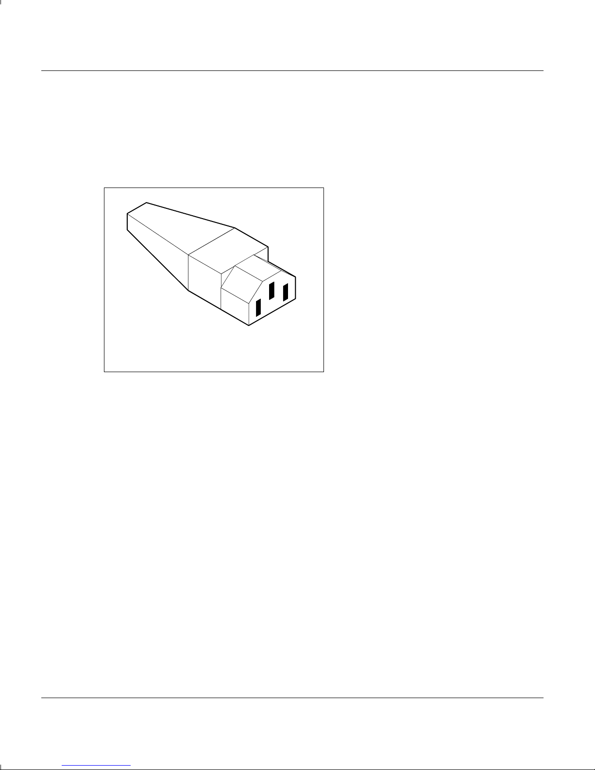
Important notice concerning power cord selection
The power cord for this unit has been packed separately and has been selected
according to the country of destination and must be used to prevent electric shock. Use
the following guidelines if it is necessary to replace the original cord set.
The female receptacle of the cord set must
meet CEE-22 requirements and will look
like Figure 1.
Figure 1
For the United States and Canada:
Use a UL listed and CSA labelled cord set consisting of a three conductor cord with a
maximum of 15-feet in length.
For units which stand on a desk or table, type SVT or SJT cord sets shall be used.
For units which stand on floor, only SJT type cord sets shall be used.
The cord set must be selected according to the current rating for your unit. Please consult
Table A for the selection criteria for power cords used in the United States and Canada.
10 A26361-K293-Z1-1-7619
Important notes
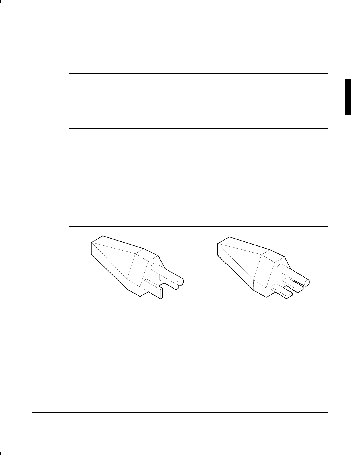
Figure 2
Figure 3
Table A:
Cord Type Size of Conductors Maximum Current
in Cord Rating of Unit
SJT 18 AWG 10 Amps
16 AWG 12 Amps
14 AWG 12 Amps
SVT 18 AWG 10 Amps
17 AWG 12 Amps
For units set at 115 V:
use a parallel blade, grounding type attachment plug rated 15 A, 125 V (Figure 2).
For units set at 230 V (domestic use):
use a tandem blade, grounding type attachment plug rated 15 A, 250 V (Figure 3).
For units set at 230 V (outside of the United States and Canada):
use a cord set consisting of a minimum AWG according to Table A and a grounding type
attachment plug rated 15 A, 250 V. The cord set should have the appropriate safety
approvals for the country in which the equipment will be installed and marked HAR.
A26361-K293-Z1-1-7619 11

Important notes
For the United Kingdom
Should the plug on the flexible cord not be of the type for your socket outlets do not use
an adapter but remove the plug from the cord and discard. Carefully prepare the end of
the supply cord and fit a suitable plug.
WARNING
THIS APPLIANCE MUST BE EARTHED
IMPORTANT
The wires in this mains lead are coloured in accordance with the following code:
Green and Yellow: Earth
Blue: Neutral
Brown: Live
As the colours of the wires in the mains lead of this appliance may not correspond with
the coloured markings identifying the terminals in your plug, proceed as follows:
– The wire which is coloured Green and Yellow must be connected to the terminal in the
plug which is marked with the letter E or by the earth symbol ⊥ or coloured Green or
Green and Yellow.
– The wire which is coloured Blue must be connected to the terminal which is marked
with the letter N or coloured Black.
– The wire which is coloured Brown must be connected to the terminal which is marked
with the letter L or coloured Red.
12 A26361-K293-Z1-1-7619
Installation
A26361-K293-Z1-1-7619 13
Installation The constituents of your PC
This chapter describes the standard routine of installing your PC for the first time. It
indicates how to select the right video workstation and contains illustrations showing how
to install the PC and cable the units.
Please take note of the "Important Notes" at the beginning of this Operating
!
Manual.
The constituents of your PC
The PC consists of the following
hardware components:
- System unit
- Monitor
- Keyboard
Useful add-ons (optional):
- System expansion boards
- Mouse
- Printer
- Scanner
14 A26361-K293-Z1-1-7619
Window
30˚
30˚
65˚
65˚
0˚
60˚
0˚
edge of desk
permissible viewing sector
permissible
reaching sector
600 mm
permissible
reaching sector
600 mm
preferable viewing sector
permissible
viewing sector
approx 90˚
and
more
approx 90˚
The ergonomic video workstation Installation
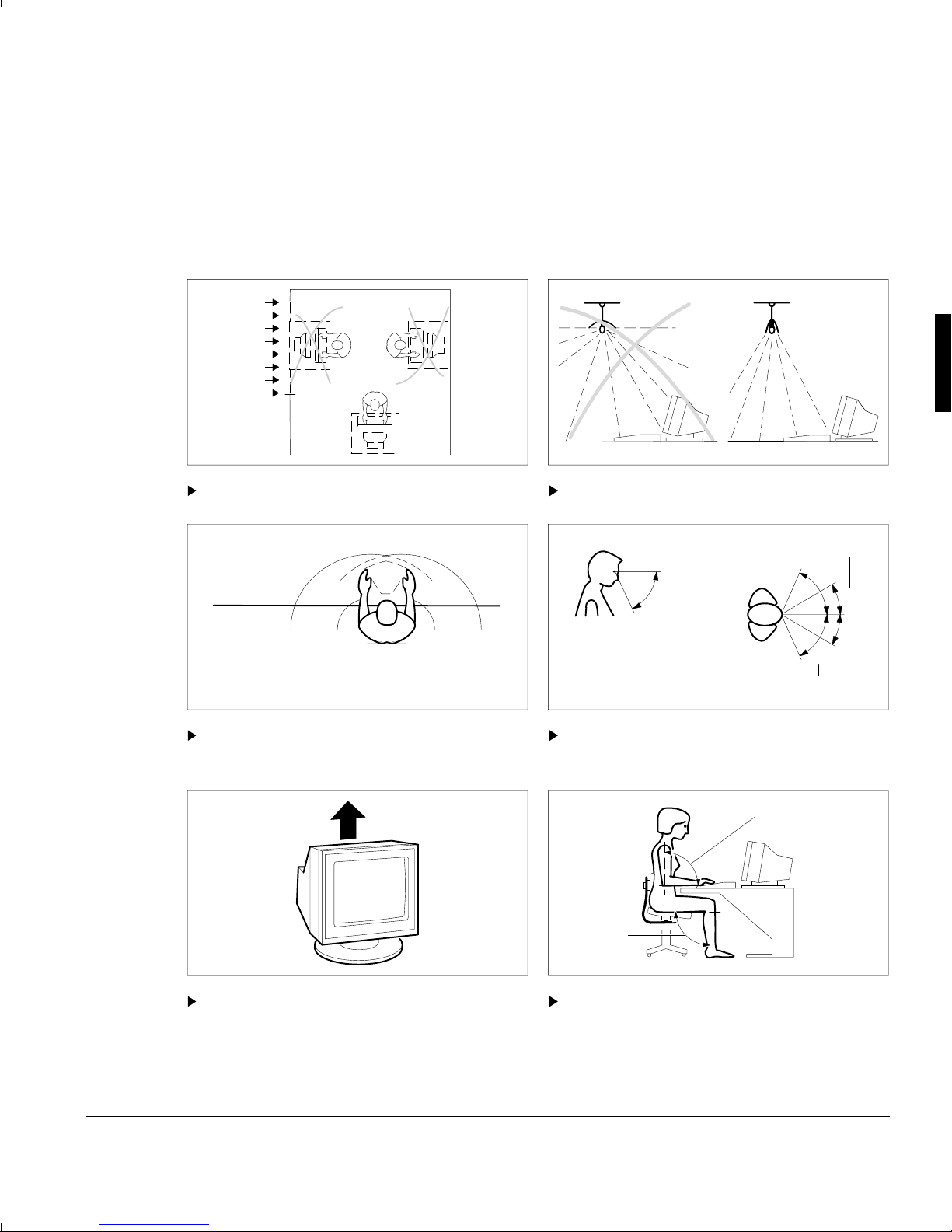
Setting up an ergonomic video workstation
Before you set up your PC you should select a suitable position for working at the
monitor. Please observe the following advice when installing a video workstation.
Avoid direct and indirect glare. Avoid indirect glare from light sources.
Place the keyboard in the optimum Place the screen in the viewing sector.
reaching sector.
Keep the ventilation areas of the display Make sure you assume the correct
unit free. posture.
A26361-K293-Z1-1-7619 15
Installation Contents of the Consignment
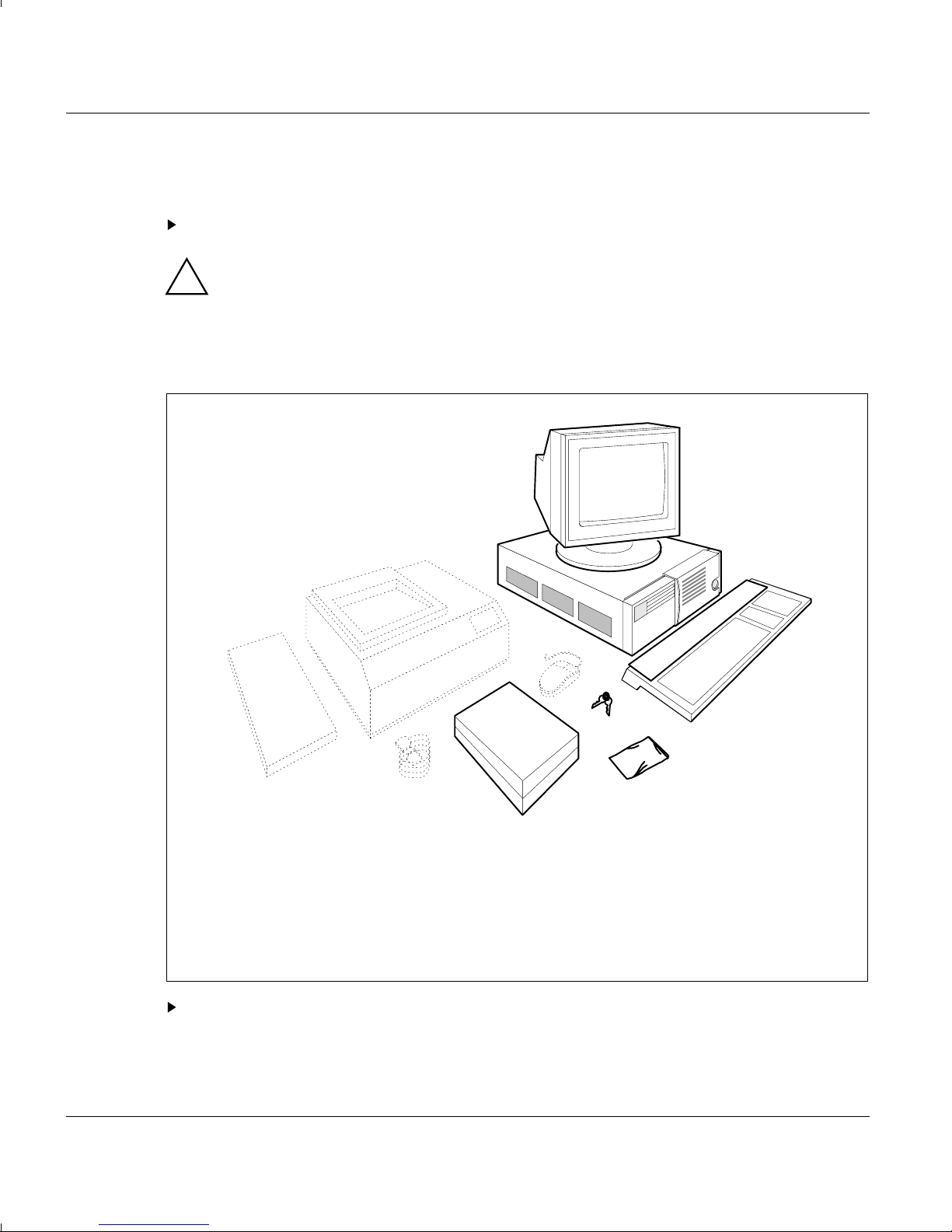
Unpacking and checking the contents of the consignment
Please unpack all the individual parts.
Do not throw away the original packing material!
!
It may be required for reshipment at some later date.
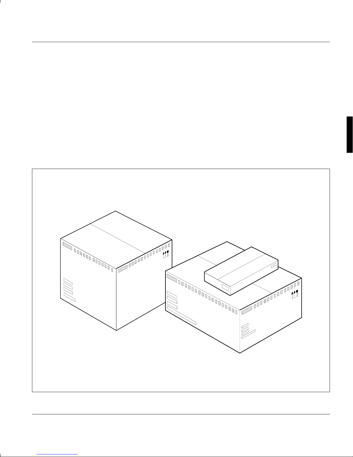
Contents of the consignment
5
4
7
10
1
8
1 = Operating Manual
2 = Operating system User´s Manual
with floppy disks
3 = Keyboard with cable
4 = System Unit and power cable
5 = Monitor (depending on variant)
9
6
2
6 = 2 Keys
7 = Printer (option)
8 = Interface cable for printer (option)
9 = Mouse (option)
10 = Expansions (option)
11 = Accessories
Check the consignment for damage incurred during transport.
3
11
16 A26361-K293-Z1-1-7619

Settings Installation
Check whether the consignment agrees with the details in the delivery note (missing
items, serial number on the nameplate on the rear of the system unit).
Should you discover the equipment has been damaged in transport or that the
i
consignment does not correspond to the delivery note, notify your local sales office
immediately.
Settings
The boards and modules are set to the correct values at the factory.
However, always check that the correct voltage has been set before connecting the
!
equipment to a power source. If the setting for the rated voltage is incorrect, your
equipment may be damaged.
Setting the rated voltage
The system unit automatically sets itself to the correct voltage within the range from
110 V to 240 V.
Always check that the correct voltage has been set at the printers, scanners and
!
monitors.
Setting expansion modules
Make all the necessary settings on your expansion module. The settings can be found in
the documentation supplied with the module.
Setting the monitor
Make the necessary settings on your monitor. These settings can be found in the
documentation supplied with the monitor.
A26361-K293-Z1-1-7619 17

Installation Installing the PC
Installing expansion modules
Once you have completed making the necessary settings on the expansion module,
install it as described under the chapter headed "System Unit".
Pull out the power plug before opening the housing!
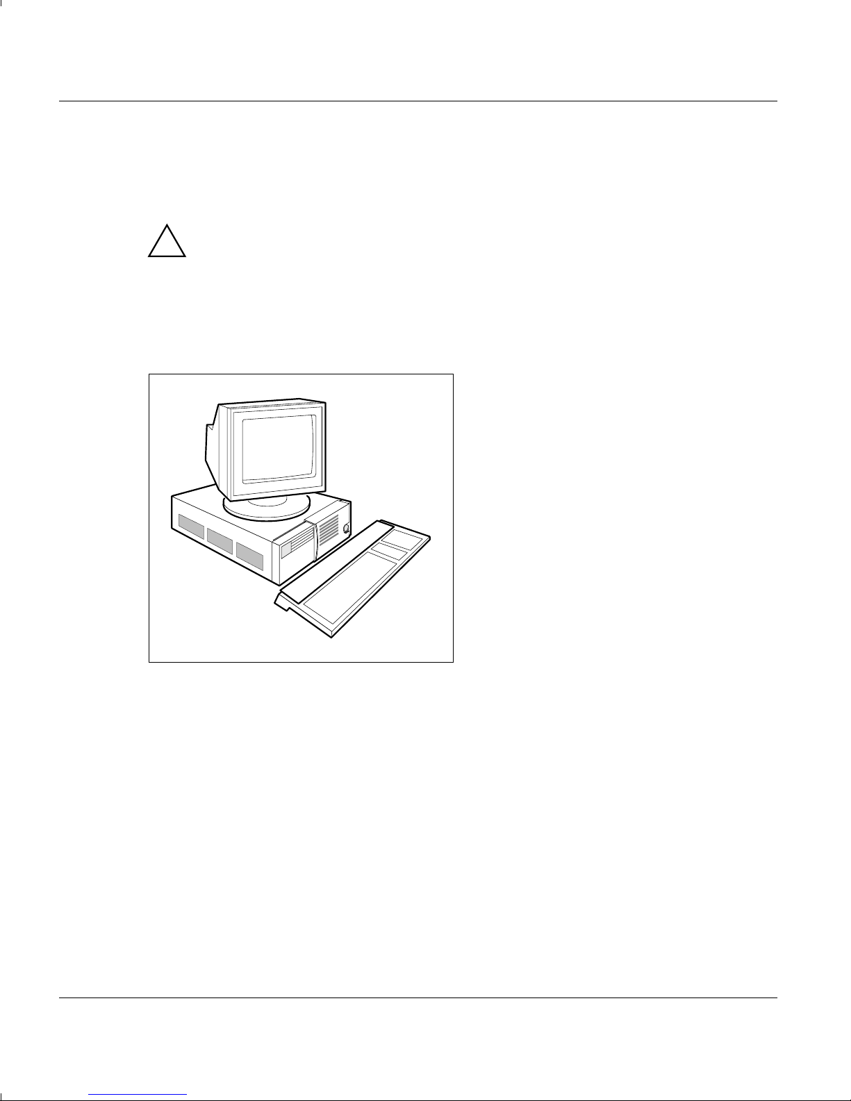
Installing the PC
We recommend that you place your equipment on a surface with good anti-slip
!
qualities.
In view of the multitude of different finishes and varnishes used on furniture, it is
possible that the PC's rubber feet will mark the surface it stands on.
Your PC should not be exposed to extreme environmental conditions. Protect it
from dust, humidity and heat.
A space of 200 mm must remain free both in front of and behind the system unit to
enable proper ventilation. The ventilation grid on the monitor must not be
obstructed.
When you install your PC, follow the advice given on setting up an ergonomic
workstation. Everyone who uses the workstation will appreciate it if you do.
Place the system unit on your workstation.
Ensure that it is freely accessible at the front.
i
Place the monitor on the desk.
Place the keyboard in front of the system unit.
18 A26361-K293-Z1-1-7619

Cabling the PC Installation
Cabling the PC
The power plug must be pulled out!
No cable should be connected or disconnected during a thunderstorm.
!
Never unplug a cable by pulling the cable itself. Always take hold of the actual plug
body.
When you install the system unit or extensions, you should connect and disconnect the
cables in the following order.
Connecting cables
Turn off all power and equipment switches.
Pull all power plugs out of the grounded-contact utility power sockets.
Plug all cables into the system unit and peripherals. Please note anyway the
information provided in the chapter "Safety".
Plug all data communication cables into the utility sockets.
Plug all power cables into the grounded-contact utility power sockets.
Disconnecting cables
Turn off all power and equipment switches.
Pull all power plugs out of the grounded-contact utility power sockets.
Unplug all data communication cables from the utility sockets.
Disconnect all cables from the system unit and peripherals.
A26361-K293-Z1-1-7619 19
Installation Cabling the PC
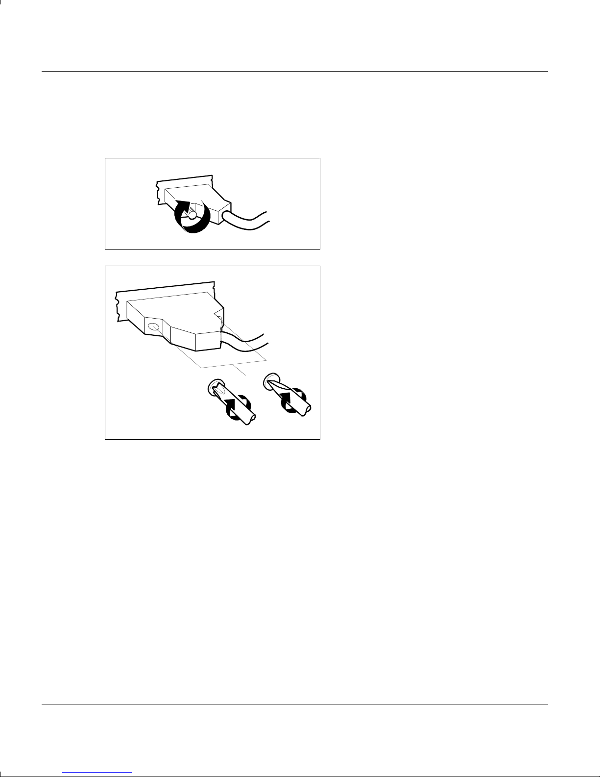
Fastening the interface connector
Some interface connectors have a knurled screw, others Philips or ordinary screws.
Interface connectors with a knurled screw
can be tightened by hand.
Interface connectors with Philips or
ordinary screws can be tightened using a
screwdriver.
20 A26361-K293-Z1-1-7619
Cabling the PC Installation
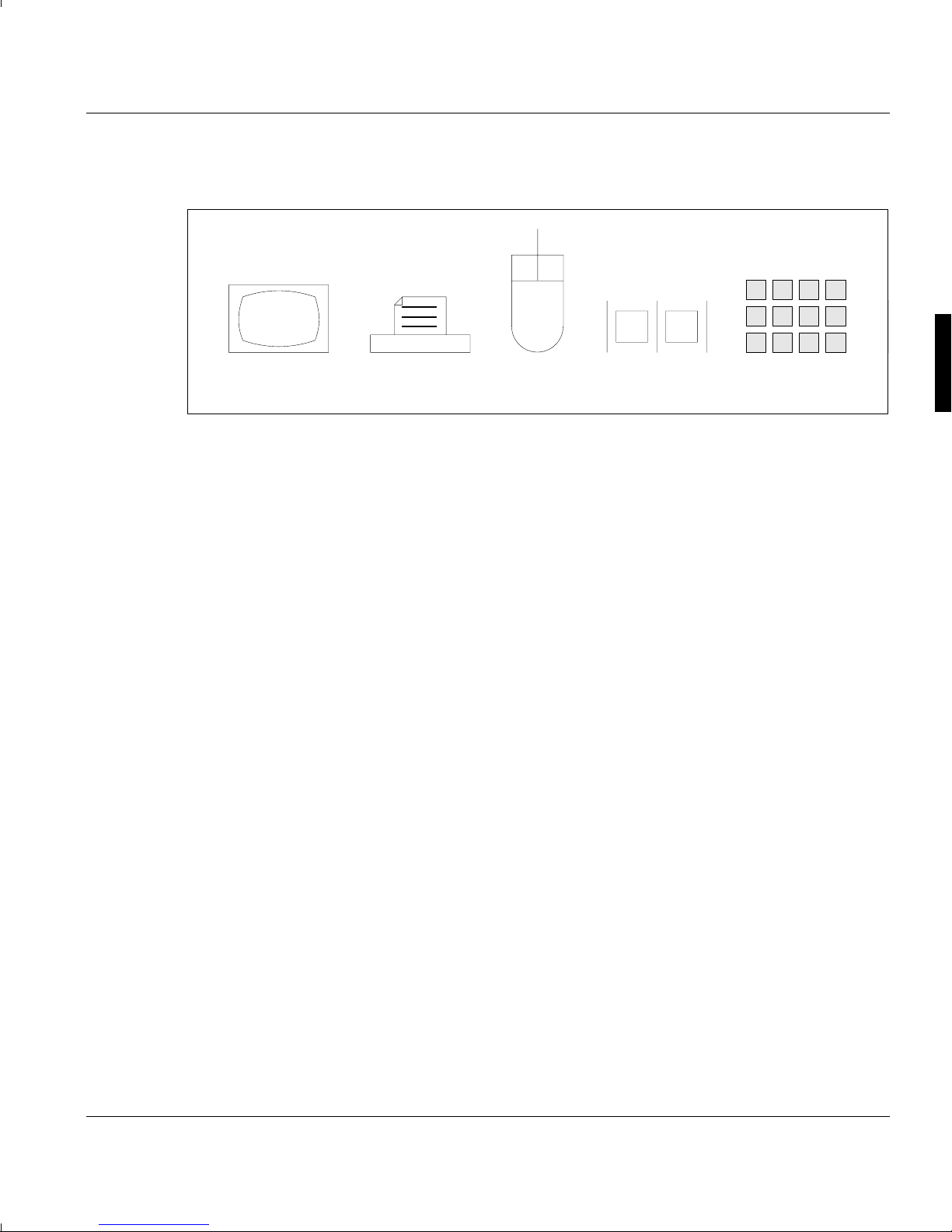
12345
Symbols at the rear of the system unit
Symbol 1 Monitor connection
Symbol 2 Parallel interface (printer connection LPT1)
Symbol 3 Serial interface (Mouse connection COM1)
Symbol 4 Serial interface (COM2)
Symbol 5 Keyboard receptacle
A26361-K293-Z1-1-7619 21

Installation Cabling the PC
Connecting the keyboard
Insert the round plug into the receptacle
on the underside of the keyboard.
Connecting the monitor
A description of how to connect your monitor can be found in the Operating Manual of
your monitor.
Insert the round plug (diode connector)
into receptacle 1.
1
22 A26361-K293-Z1-1-7619
Cabling the PC Installation
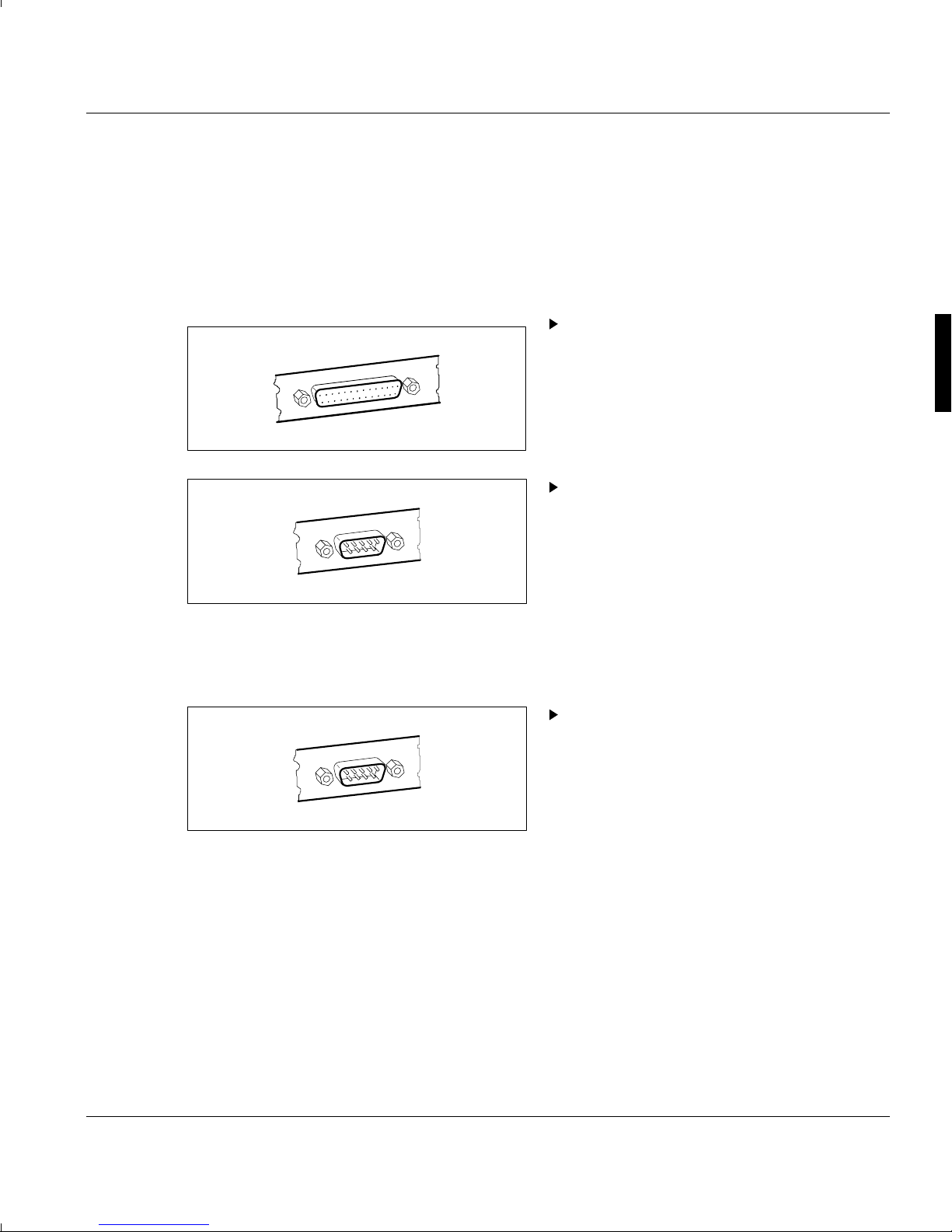
Connecting the printer
The PC's Centronics interface and RS-232C (V.24) interfaces are located at the rear of
the system unit.
As a general principle, you should use a printer with a parallel interface. This leaves a
RS-232C (V.24) serial interface free for other applications (e.g. for a mouse).
If you are using a printer with a parallel
interface, please connect the interface
cable to the Centronics interface.
If you are using a printer with a RS-232C
serial interface, please connect the
interface cable to one of the RS-232C
(V.24) interfaces.
Connecting the mouse
Connect the mouse to one of the RS232C (V.24) interfaces.
Detailed information on the installation of
the mouse (control unit and programs)
may be found in the manual supplied
with it.
A26361-K293-Z1-1-7619 23
 Loading...