

Siemens Nixdorf MCM 21T1 Service Manual

MCM 21T1
SERVICE MANUAL
SPECIFICATIONS
AEP Model
Chassis No. SCC-L04S-A
N3
CHASSIS
COLOR Monitor
MCM 21T1
SAFETY CHECK-OUT
After correcting the original service problem, perform the following safety checks before releasing the set to the customer:
1. Check the area of your repair for unsoldered or poorly-soldered connections. Check the entire board surface for solder
splashes and bridges.
2. Check the interboard wiring to ensure that no wires are
“pinched” or contact high-wattage resistors.
3. Check that all control knobs, shields, covers, ground straps,
and mounting hardware have been replaced. Be absolutely
certain that you have replaced all the insulators.
4. Look for unauthorized replacement parts, particularly transistors, that were installed during a previous repair. Point
them out to the customer and recommend their replacement.
5. Look for parts which, though functioning, show obvious
signs of deterioration. Point them out to the customer and
recommend their replacement.
6. Check the line cords for cracks and abrasion. Recommend
the replacement of any such line cord to the customer.
7. Check the B+ and HV to see if they are specified values.
Make sure your instruments are accurate; be suspicious of
your HV meter if sets always have low HV.
8. Check the antenna terminals, metal trim, “metallized”
knobs, screws, and all other exposed metal parts for AC
Leakage. Check leakage as described below.
To Exposed Metal
Parts on Set
AC
0.15 µF
1.5 k
Ω
Voltmeter
(0.75 V)
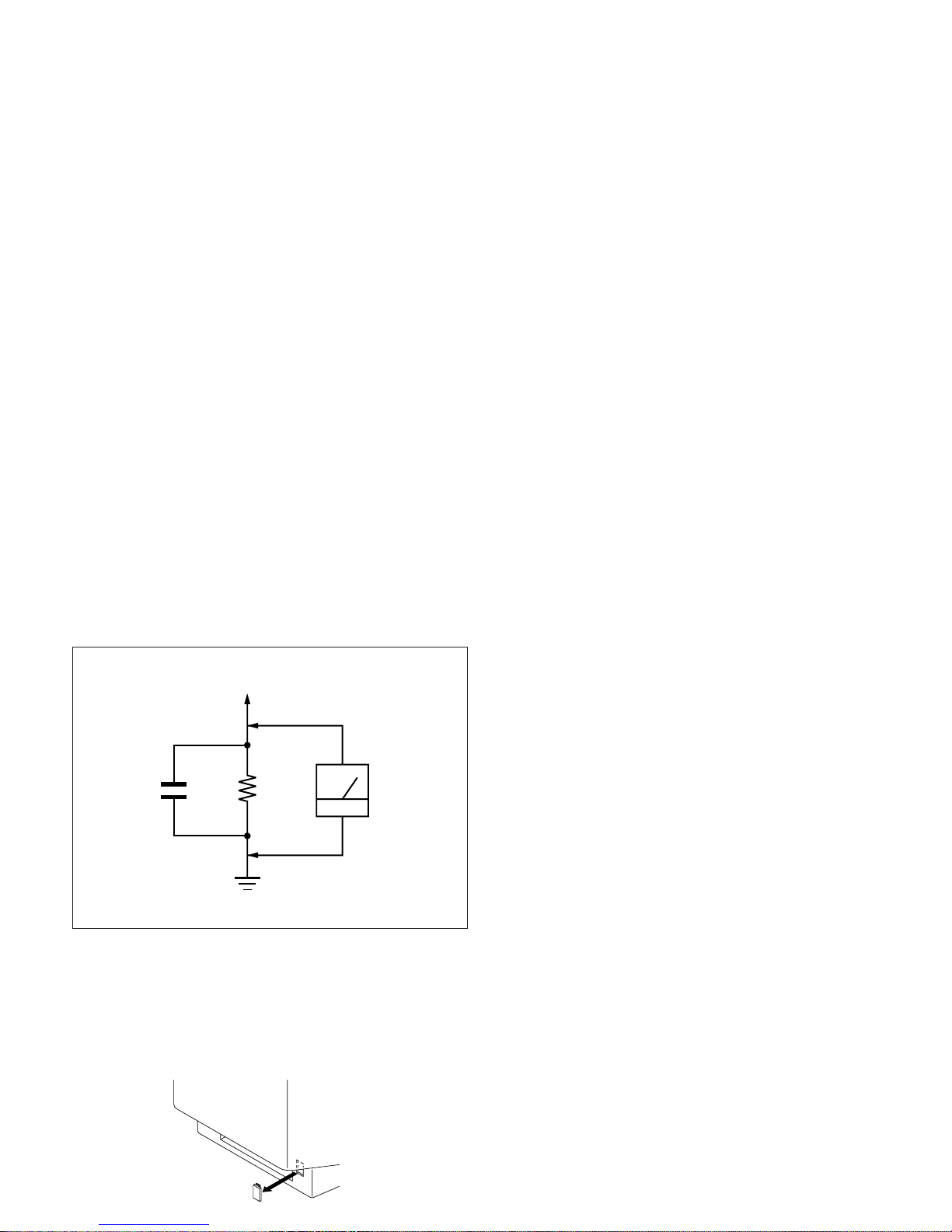
LEAKAGE TEST
The AC leakage from any exposed metal part to earth ground
and from all exposed metal parts to any exposed metal part having a return to chassis, must not exceed 0.5 mA (500
microampers).
Leakage current can be measured by any one of three methods.
1. A commercial leakage tester, such as the Simpson 229 or
RCA WT-540A. Follow the manufacturers’ instructions to
use these instruments.
2. A battery-operated AC milliammeter. The Data Precision
245 digital multimeter is suitable for this job.
3. Measuring the voltage drop across a resistor by means of a
VOM or battery-operated AC voltmeter. The “limit” indication is 0.75 V, so analog meters must have an accurate lowvoltage scale. The Simpson 250 and Sanwa SH-63Trd are
examples of a passive VOMs that are suitable. Nearly all
battery operated digital multimeters that have a 2 V AC
range are suitable. (See Fig. A)
WARNING!!
NEVER TURN ON THE POWER IN A CONDITION IN
WHICH THE DEGAUSS COIL HAS BEEN REMOVED.
SAFETY-RELATED COMPONENT WARNING!!
COMPONENTS IDENTIFIED BY SHADING AND MARK
¡ ON THE SCHEMATIC DIAGRAMS, EXPLODED
VIEWS AND IN THE PARTS LIST ARE CRITICAL FOR
SAFE OPERATION. REPLACE THESE COMPONENTS
WITH SONY PARTS WHOSE PART NUMBERS APPEAR AS SHOWN IN THIS MANUAL OR IN SUPPLEMENTS PUBLISHED BY SONY. CIRCUIT ADJUSTMENTS THAT ARE CRITICAL FOR SAFE OPERATION
ARE IDENTIFIED IN THIS MANUAL. FOLLOW THESE
PROCEDURES WHENEVER CRITICAL COMPONENTS
ARE REPLACED OR IMPROPER OPERATION IS SUSPECTED.
Earth Ground
Fig. A. Using an AC voltmeter to check AC leakage.
CAUTION ON DAS (ECS) CONNECTOR
• The connector for DAS (ECS) adjustment is provided inside
the cover shown below. Be careful with an electrical shock
when connecting the connector with the power supplied. Also,
return the removed cover to the home position.
Rear side

POWER SAVING FUNCTION
MCM 21T1
This monitor meets the power-saving guidelines set by VESA and
Energy Star, as well as the more stringent NUTEK .
If the monitor is connected to a computer or video graphics board
that is VESA DPMS (Display Power Management Signaling)
compliant, the monitor will automatically reduce power consumption in three stages as shown below.
You can set the delay time before the monitor enters the power
saving mode using the OSD. Set the time according to “Setting
the power saving delay time”.
Power consumption
mode
Normal operation
1
Standby (1st mode)
2
Suspend (2nd mode)
3
Active-off (3rd mode)
4
Power-off
5
Screen
active
blank
blank
blank
—
Horizontal
sync signal
present
absent
present
absent
—
Vertical
sync signal
present
present
absent
absent
—
Note
If no video signal is input to the monitor, the “NO INPUT SIGNAL” message appears. After the delay time has passed, the
power saving function automatically puts the monitor into the active-off mode and the indicator lights up orange. Once the horizontal and vertical sync signals are detected, the monitor automatically resumes its normal operation mode.
Power
consumption
≤ 160 W
≤ 100 W
≤ 15 W
≤ 5 W
0 W
Recovery time
—
Approx. 3 sec.
Approx. 3 sec.
Approx. 10 sec.
—
u indicator
Green
Green and orange
alternate
Green and orange
alternate
Orange
Off
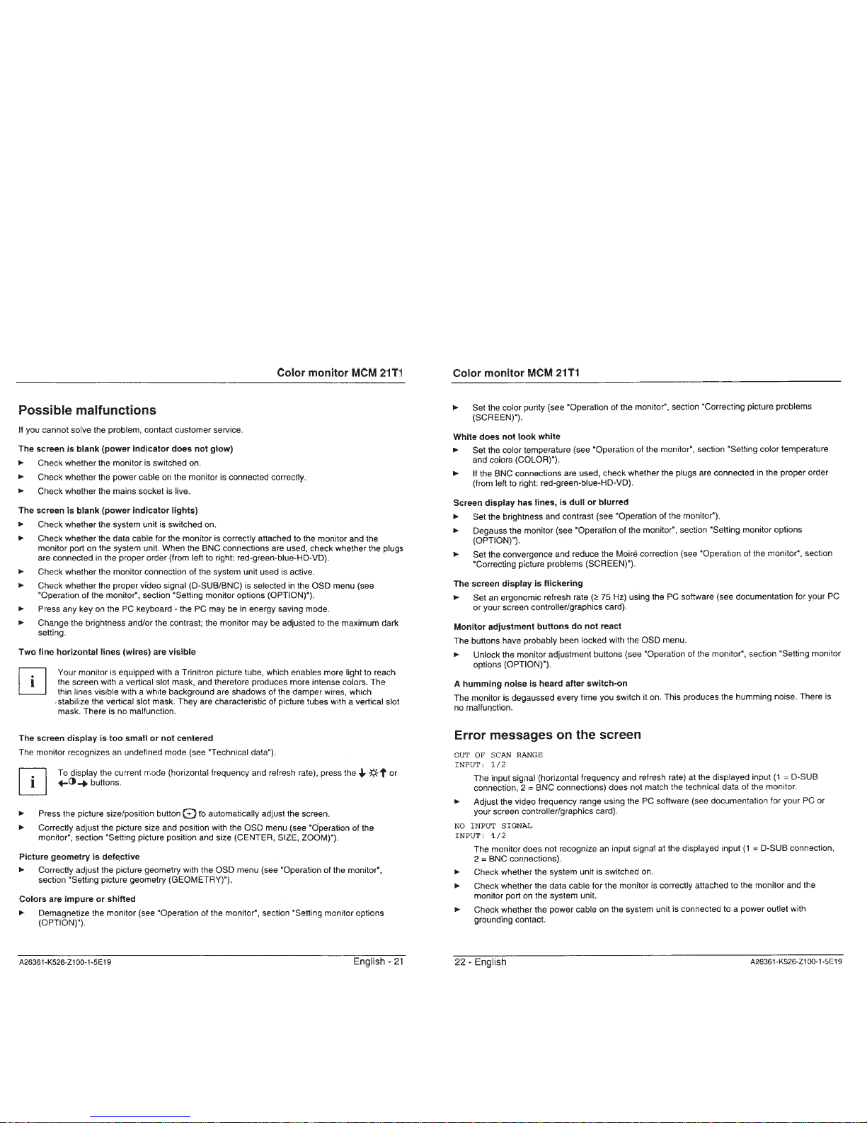
DIAGNOSIS
Failre
+B failure
Orange → Off
(0.5 sec) (0.5 sec)
Horizontal / Vertical Deflection
failure, Thermal protector
ABL protector
Orange → Off
(1.5 sec) (0.5 sec)
Orange → Off
(0.5 sec) (1.5 sec)
HV failure
Orange → Off → Orange → Off
(0.25 sec) (0.25 sec) (0.25 sec) (1.25 sec)
Aging / Self Test
Orange → Off → Green → Off
(0.5 sec) (0.5 sec) (0.5 sec) (0.5 sec)
Aging Mode (Video Aging) : During Power Save, press “MENU” key for longer than 2 second.
Self Test (OSD Color Bar) : During Power Save, press “CONTRAST” + (/) key for longer than 2 second.
Reliability Check Mode : During Power Save, press “CONTRAST” – (?) key for longer than 2 second.
Power LED
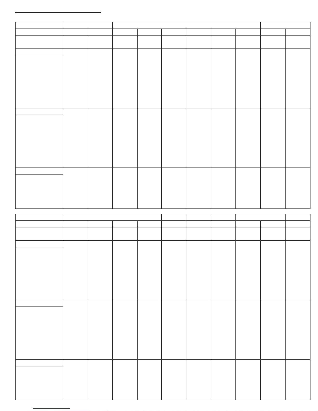
TIMING SPECIFICATION
MODE AT PRODUCTION MODE 1 MODE 2 MODE 3
MODE FOR CUSTOMER VGA E-VGA VGA VESA VESA SNI-100Hz VESA VESA SNI-100Hz MGA
RESOLUTION 720 X 400 720 X 400 640 X 480 640 X 480 640 X 480 640 X 480 800 X 600 800 X 600 800 X 600 800 X 600
CLOCK 28.325 MHz 36.082 MHz 25.175 MHz 31.500 MHz 36.000 MHz 40.500 MHz 49.500 MHz 56.250 MHz 67.500 MHz 81.000 MHz
— HORIZONTAL —
H-FREQ 31.472 kHz 37.822 kHz 31.469 kHz 37.5 kHz 43.269 kHz 50.625 kHz 46.875 kHz 53.674 kHz 63.92 kHz 76.705 kHz
usec usec usec usec usec usec usec usec usec usec
H. TOTAL 31.774 26.44 31.778 26.667 23.111 19.753 21.333 18.631 15.644 13.037
H. BLK 6.355 6.485 6.356 6.349 5.333 3.951 5.172 4.409 3.793 3.16
H. FP 0.635 0.748 0.636 0.508 1.556 0.395 0.323 0.569 0.474 0.395
H. SYNC 3.813 1.247 3.813 2.032 1.556 1.58 1.616 1.138 0.948 1.185
H. BP 1.906 4.49 1.907 3.81 2.222 1.975 3.232 2.702 2.37 1.58
H. ACTIV 25.419 19.955 25.422 20.317 17.778 15.802 16.162 14.222 11.852 9.877
— VERTICAL —
V. FREQ(HZ) 70.094 Hz 84.236 Hz 59.94 Hz 75 Hz 85.008 Hz 100.049 Hz 75 Hz 85.061 Hz 100.032 Hz 120.038 Hz
lines lines lines lines lines lines lines lines lines lines
V. TOTAL 449 449 525 500 509 506 625 631 639 639
V. BLK 49 49 45 20 29 26 25 31 39 39
V. FP 13 9 10 1 1 1 1 1 1 2
V. SYNC 2 3 2 3 3 3 3 3 3 3
V. BP 34 37 33 16 25 22 21 27 35 34
V. ACTIV 400 400 480 480 480 480 600 600 600 600
— SYNC —
INT(G) NO NO NO NO NO NO NO NO NO NO
EXT(H/V)/POLARITY YES N/P YES N/P YES N/N YES N/N YES N/N YES N/N YES P/P YES P/P YES P/P YES N/N
EXT(CS) /POLARITY NO NO NO NO NO NO NO NO NO NO
INT/NON INT NON INT NON INT NON INT NON INT NON INT NON INT NON INT NON INT NON INT NON INT
SIZE(21") 388x291 mm 388x291 mm 388x291 mm 388x291 mm 388x291 mm 388x291 mm 388x291 mm 388x291 mm 388x291 mm 388x291 mm
MODE AT PRODUCTION MODE 4 MODE 5 MODE 6 MODE 7 MODE 8 MODE 9
MODE FOR CUSTOMER VESA SNI-100Hz MGA VESA SNI-110Hz VESA VESA SNI-100Hz VESA VESA
RESOLUTION 1024 X 768 1024 X 768 1024 X 768 1152 X 864 1152 X 864 1280 X 1024 1280 X 1024 1280 X 1024 1600 X 1200 1600 X 1200
CLOCK 94.5 MHz 111.2 MHz 131 MHz 108 MHz 157 MHz 135 MHz 157.5 MHz 184.9 MHz 202.5 MHz 229.5 MHz
— HORIZONTAL —
H-FREQ 68.677 kHz 80.814 kHz 97.47 kHz 67.5 kHz 100.128 kHz 79.976 kHz 91.146 kHz 107 kHz 93.75 kHz 106.25 kHz
usec usec usec usec usec usec usec usec usec usec
H. TOTAL 14.561 12.374 10.26 14.815 9.987 12.504 10.971 9.346 10.667 9.412
H. BLK 3.725 3.165 2.443 4.148 2.65 3.022 2.844 2.423 2.765 2.44
H. FP 0.508 0.288 0.244 0.593 0.204 0.119 0.406 0.173 0.316 0.279
H. SYNC 1.016 1.151 0.977 1.185 0.815 1.067 1.016 0.692 0.948 0.837
H. BP 2.201 1.727 1.221 2.37 1.631 1.837 1.422 1.558 1.501 1.325
H. ACTIV 10.836 9.209 7.817 10.667 7.338 9.481 8.127 6.923 7.901 6.972
— VERTICAL —
V. FREQ(HZ) 84.997 Hz 99.894 Hz 120.334 Hz 75 Hz 110.03 Hz 75.025 Hz 85.024 Hz 99.91 Hz 75 Hz 85 Hz
lines lines lines lines lines lines lines lines lines lines
V. TOTAL 808 809 810 900 910 1066 1072 1071 1250 1250
V. BLK 40 41 42 36 46 42 48 47 50 50
V. FP 1221211211
V. SYNC 3 3 3 3 3 3 3 3 3 3
V. BP 36 36 37 32 41 38 44 42 46 46
V. ACTIV 768 768 768 864 864 1024 1024 1024 1200 1200
— SYNC —
INT(G) NO NO NO NO NO NO NO NO NO NO
EXT(H/V)/POLARITY YES P/P YES N/N YES N/N YES P/P YES N/N YES P/P YES P/P YES P/P YES P/P YES P/P
EXT(CS) /POLARITY NO NO NO NO NO NO NO NO NO NO
INT/NON INT NON INT NON INT NON INT NON INT NON INT NON INT NON INT NON INT NON INT NON INT
SIZE(21") 388X291 mm 388X291 mm 388X291 mm 388X291 mm 388X291 mm 364X291 mm 364X291 mm 364X291 mm 388X291 mm 388X291 mm
’98.06.05 Ver.

TABLE OF CONTENTS
Section Title Page
1. GENERAL ................................................................. 1-1
2. DISASSEMBLY
2-1. Cabinet Removal ............................................... 2-1
2-2. D Board Removal .............................................. 2-1
2-3. G Board Removal .............................................. 2-2
2-4. A Board Removal .............................................. 2-2
2-5. L Board Removal .............................................. 2-3
2-6. I/O TERMINAL Board Assy Removal ............. 2-3
2-7. Service Position .................................................. 2-4
2-8. H and J Boards Removal ................................... 2-4
2-9. Picture Tube Removal ....................................... 2-5
3. SAFETY RELATED ADJUSTMENT............. 3-1
4. ADJUSTMENTS ..................................................... 4-1
5. DIAGRAMS
5-1. Block Diagrams .................................................. 5-1
5-2. Frame Shcematic Diagram ................................. 5-7
5-3. Circuit Boards Location ..................................... 5-9
5-4. Schematic Diagrams and Printed Wiring
Boards ................................................................. 5-9
(1) Schematic Diagram of D Board ........................ 5-13
(2) Schematic Diagrams of G, GA, H, J and
L Boards ............................................................ 5-17
(3) Schematic Diagram of A Board ........................ 5-24
5-5. Semiconductors ................................................. 5-29
6. EXPLODED VIEWS
6-1. Chassis ............................................................... 6-1
6-2. Picture Tube ...................................................... 6-2
6-3. Packing Materials ............................................... 6-3
7. ELECTRICAL PARTS LIST ............................ 7-1

SECTION 1
GENERAL
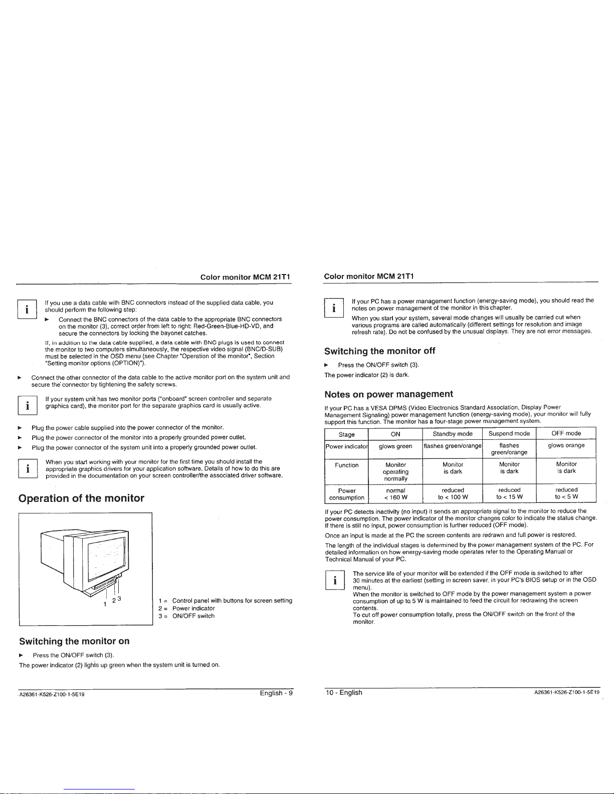
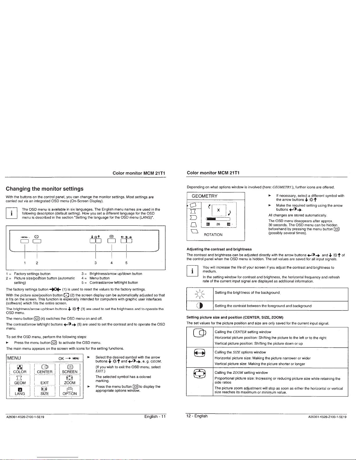
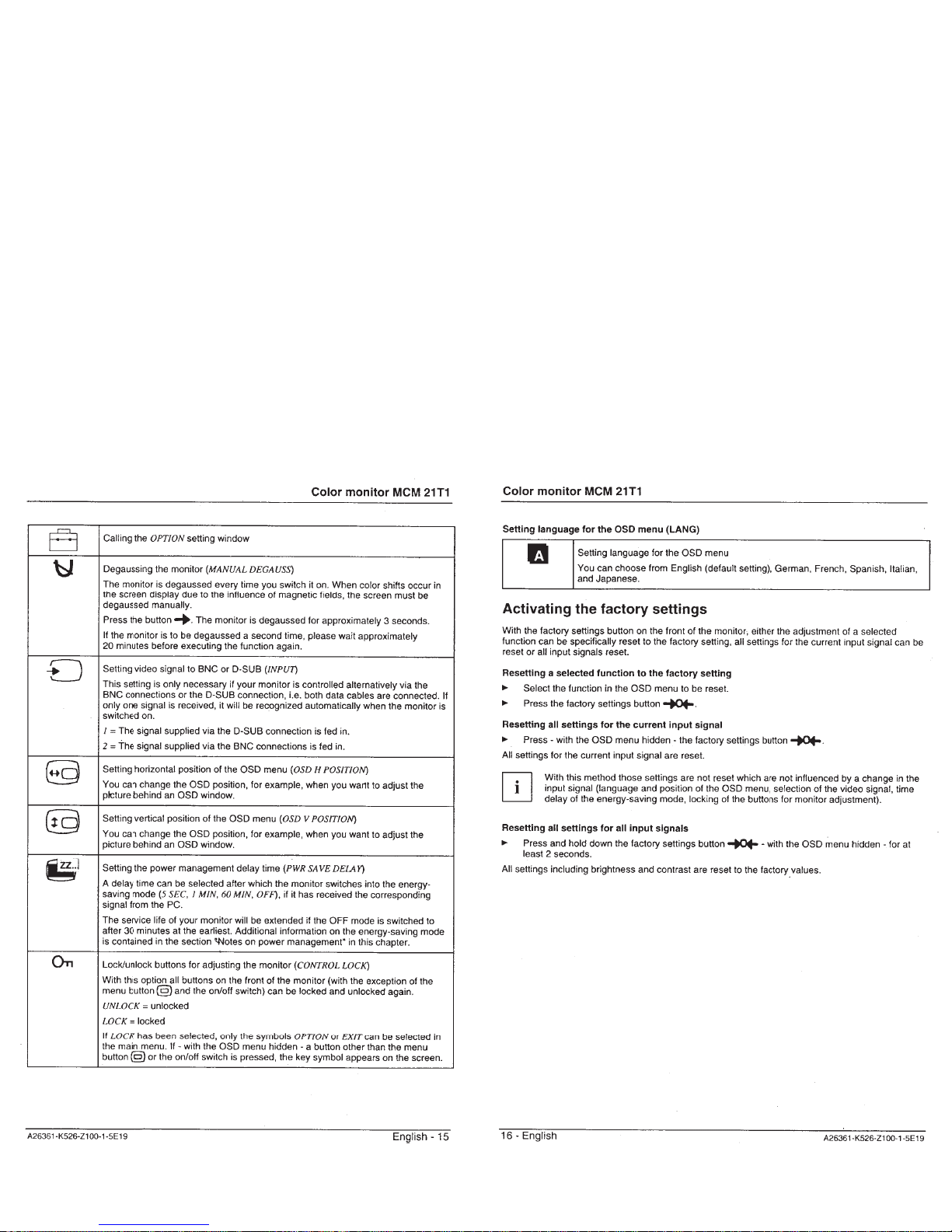
The operating instructions mentioned here are partial abstracts
from the Operating Instruction Manual. The page numbers of
the Operating Instruction Manual remain as in the manual.
1-1
1-2


1-5

 Loading...