

Page 1
1
882
QFM31..
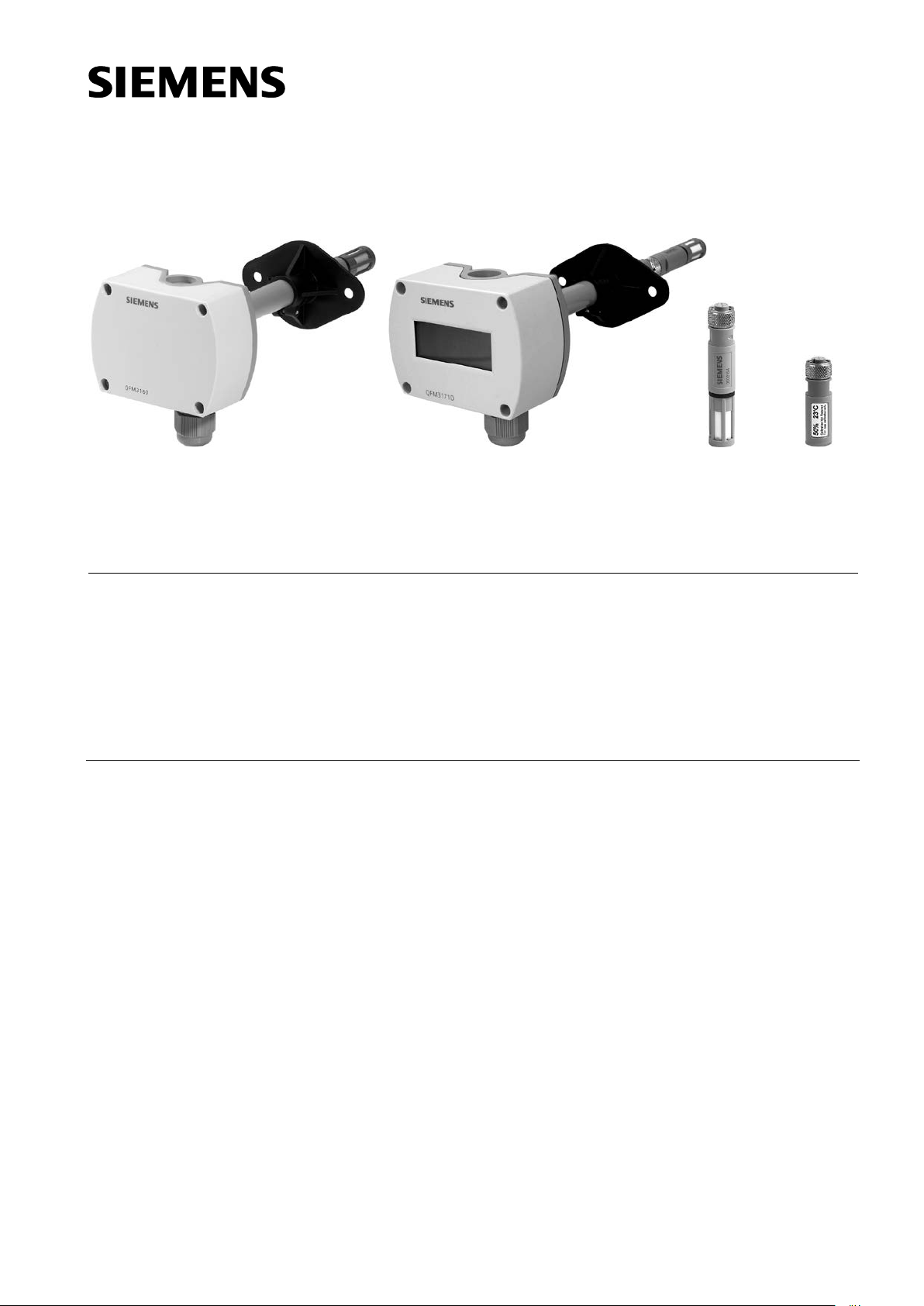
QFM3160D /QFM3171D
AQF3150 AQF3153
Symaro™
Duct sensors
QFM31…
for relative humidity (high accuracy) and temperature
Examples
1882P01
1859P02
1859P04
• Operating voltage AC 24 V / DC 13.5...35 V
• Signal output DC 0...10 V / 4…20 mA for relative humidity and temperature
• Very high measuring accuracy across the entire measuring range
• Function test
• Capacitive humidity measurement
• Range of use −40…+70 °C / 0…100 % r. h.
with LCD display
Use
The QFM31… is for use in ventilation and air conditioning plants where high accuracy
and short response times for measuring relative humidity are required. The measuring
range covers the entire humidity range of 0…100 %.
• Storage and production facilities in the paper, textile, pharmaceutical, food, chemical
and electronics industry, etc.
• Laboratories
• Hospitals
• Computer and EDP centers
• Indoor swimming pools
• Greenhouses
The QFM31… is used as a
• control sensors in the supply or extract air
• limit sensor for maximum limitation of supply air humidity after a steam humidifier
• limit sensor, e.g. for measured value indication or for connection to a building
automation and control system
• sensor for enthalpy and absolute humidity, together with the SEZ220 (see Data
Sheet N5146)
−25…+70 °C / 0…100 % r.h.
CE1N1882en
2014-07-30
Building Technologies
Page 2
Type summary
Type
Temperature
Temperature
Humidity
Humidity
Operating
Measured
QFM3100
None
None
0...100 %
active, DC 0...10 V
AC 24 V or
No
QFM3101
None
None
0...100 %
active, 4…20 mA
DC 13,5…35 V
No
QFM3160
0...50 °C / − 40…+70 °C /
active, DC 0...10 V
0...100 %
active, DC 0...10 V
AC 24 V or
No
QFM3160D
0...50 °C / − 40…+70 °C /
active, DC 0...10 V
0...100 %
active, DC 0...10 V
AC 24 V or
Yes
QFM3171
0...50 °C / − 40…+70 °C /
active, 4…20 mA
0...100 %
active, 4…20 mA
DC 13,5…35 V
No
QFM3171D
0...50 °C / − 40…+70 °C /
active, 4…20 mA
0...100 %
active, 4…20 mA
DC 13,5…35 V
Yes
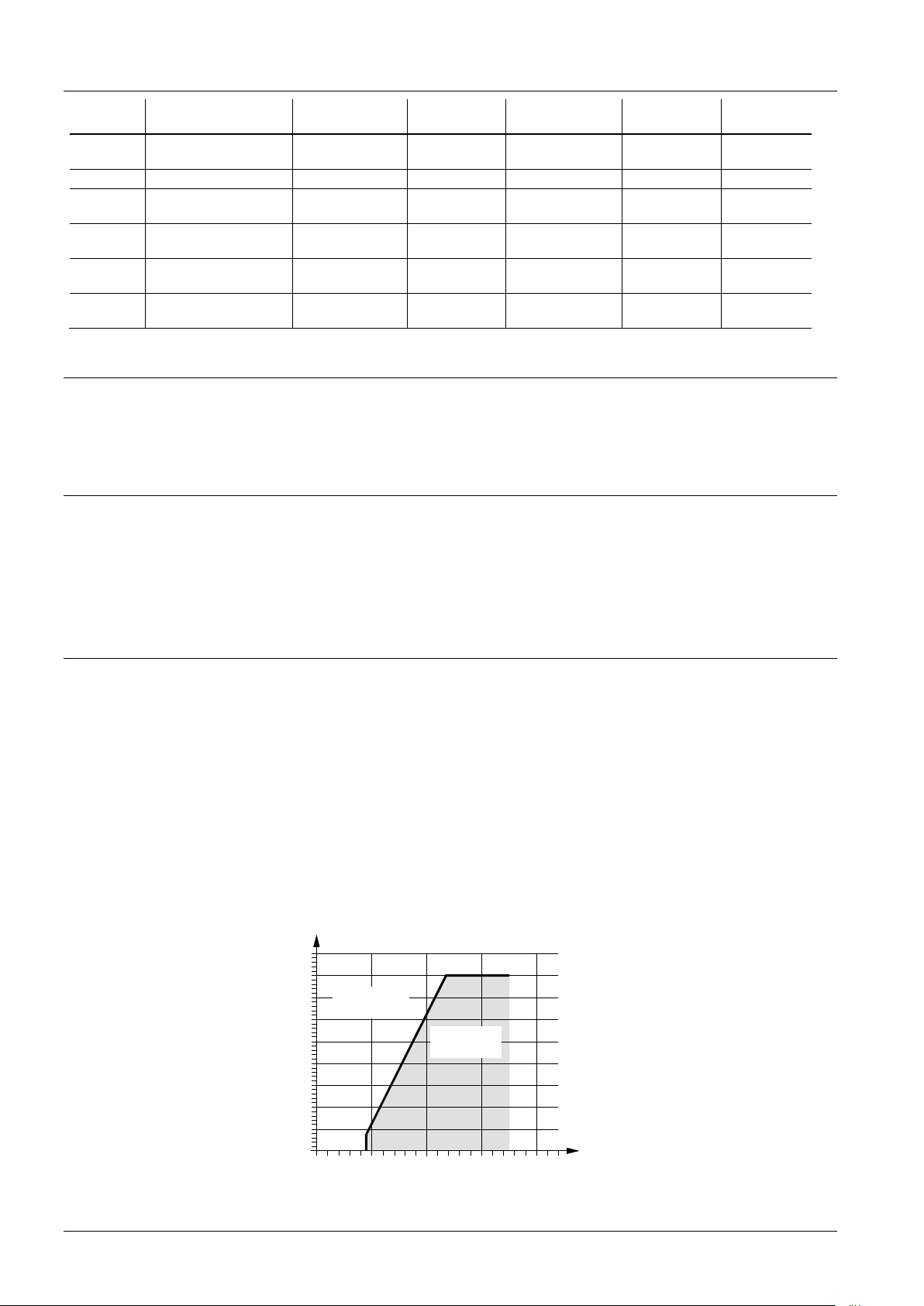
0 10 20 30 40
700
400
300
800
900
600
500
100
0
200
Burden [Ohm]
[DC V]
Operating voltage
Admissible
range
Inadmissible
range!
1882D02en
Relative humidity
Temperature
Burden diagram
reference
measuring range
− 35...+ 35 °C
− 35...+ 35 °C
− 35...+ 35 °C
− 35...+ 35 °C
Ordering and delivery
Equipment combinations
signal output
measuring range
signal output
voltage
DC 13,5…35 V
DC 13,5…35 V
DC 13,5…35 V
value display
When ordering, please give name and type reference, e.g.:
Duct sensor QFM3160
Place a separate order for the service set AQF3153 listed under accessories.
All systems and devices capable of acquiring and handling the sensor’s DC 0...10 V or
4...20 mA output signal.
When using the sensors for minimum or maximum selection, for averaging, or to
calculate enthalpy, enthalpy difference, absolute humidity, and dew point, we
recommend to use the SEZ220 signal converter (see Data Sheet N5146).
Technical design
2/7
Siemens Duct sensors QFM31… CE1N1882en
Building Technologies 2014-07-30
The sensor acquires the relative humidity in the air duct via its capacitive humidity
sensing element whose capacitance varies as a function of the relative humidity of the
ambient air.
An electronic circuit converts the sensor’s signal to a continuous DC 0...10 V or
4…20 mA signal, corresponding to a relative humidity of 0...100 %.
The sensor acquires the temperature in the air duct via its sensing element whose
electrical resistance changes as a function of the temperature.
This variation is converted to an active DC 0…10 V or 4…20 mA output signal,
depending on the type of sensor. The output signal corresponds to a selectable
temperature range of 0…50 °C, –35…+35 °C, or −40...+70 °C.
Output signal, terminal I1 / I2
Page 3
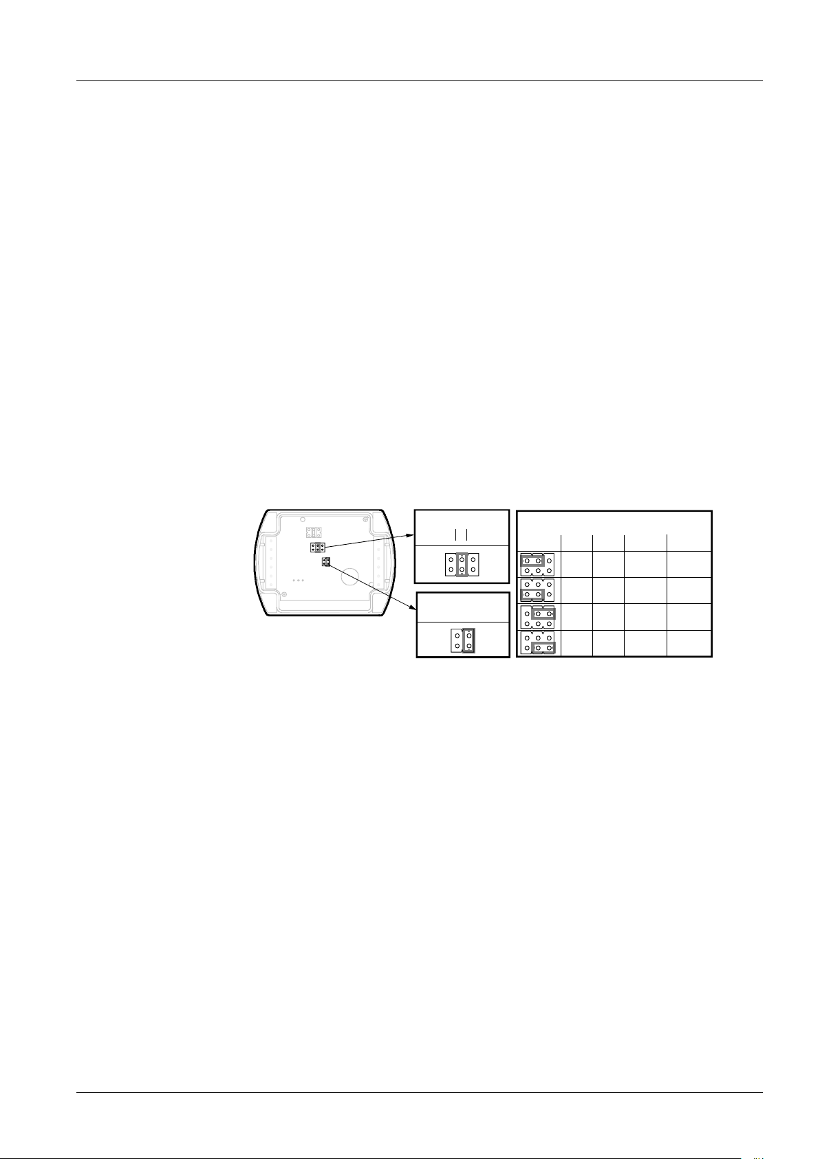
Mechanical design
1 2
3
1
2
3
Range
5 V
10 V
5 V
0 V
10 V
5 V
0 V
5 V
U1 U2
I1 I2
20 mA
12 mA
4 mA
12 mA
12 mA
20 mA
12 mA
4 mA
°F °C
°F °C
QFM31...D
Measuring range
Test function active
1882Z01en
Display
temperature unit
Measured value display
Setting element
The duct sensor consists of a housing, a printed circuit board, connection terminals, a
mounting flange and an immersion rod having a measuring tip.
The two-part housing comprises a base and a screwed removable cover.
A rubber seal is installed between the base and the cover in order to satisfy the
requirements of IP 65 degree of protection.
The measuring circuit and the setting element are accommodated on the printed circuit
board inside the cover, the connection terminals on the base.
The measuring tip is screwed on the immersion rod of the housing.
The sensing elements are located at the end of the measuring tip and protected by the
filter cap.
Cable entry is made via the cable entry gland M16 (IP 54) supplied with the sensor,
which can be screwed into the housing.
Immersion rod and housing are made of plastic and rigidly connected.
The sensor is fitted with the mounting flange supplied with the sensor. The flange is to
be placed over the immersion rod and then secured in accordance with the required
immersion length.
The types QFM3160D and QFM3171D provide the measured values on its LCD
display..The following measured values are displayed alternately in intervals of 5 s:
Temperature: in °C or °F
Humidity: in % r. h.
3/7
Siemens Duct sensors QFM31… CE1N1882en
Building Technologies 2014-07-30
The setting elements are located inside the cover. A setting element consists of 6 pins
and a jumper. It is used for selecting the required temperature measuring range and for
activating the test function. Types with LCD display have a second setting element with
4 pins and a jumper.
The different jumper positions have the following meaning:
• For the active temperature measuring range:
Jumper in the left position (R1) = − 35...+ 35 °C,
Jumper in the middle position (R2) = 0...50 °C (factory setting)
Jumper in the right position (R3) = −40…+70 °C
• For the active test function:
Jumper in the horizontal position: The values available at the signal output are those
given in the table “Test function active“
• For the measured value display (QFM31…D)
- Jumper vertical in the right position = °C (factory setting)
- Jumper vertical in the left position = °F
Page 4
Name
Type reference
AQF3101
Measuring tip (exchangeable for replacement)
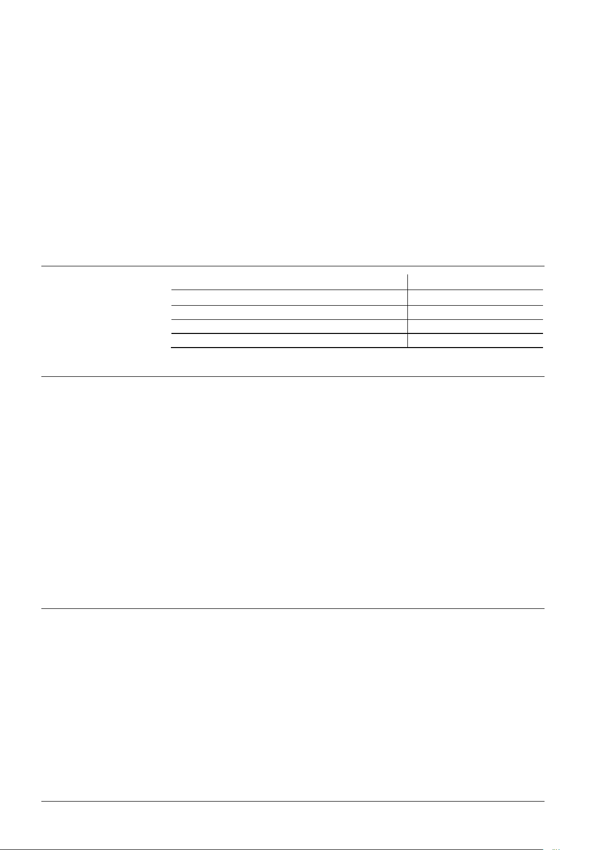
AQF3150
Service set (for function test)
AQF3153
3 m cable for remote measurement
AQY2010
Malfunction
Servi
ce set
AQF3153
Cable routing and
cable selection
Note to QFM2171(D)
Location
Caution!
Mounting instructions
Accessories
• Should the temperature sensor become faulty a voltage of 0 V (4 mA) will be applied
at signal output U2 (I2) after 60 seconds, and the humidity signal at signal output U1
(I1) will reach 10 V (20 mA).
• Should the humidity sensor become faulty a voltage of 10 V (20 mA) will be applied
at signal output U1 (I1) after 60 seconds, and the temperature signal will remain
active.
The service set comprises three measuring tips without sensor element. Each tip
signals a predefined temperature and humidity value to the basic unit:
• 85 % r. h., 40 °C
• 50 % r. h., 23 °C
• 20 % r. h., 5 °C
The fixed values are available at the signal outputs. The accuracy of the values is the
same as for the test function. The measuring tips can be exchanged in operation.
Filter cap (for replacement)
Engineering notes
Mounting notes
A transformer for safety extra low-voltage (SELV) with separate windings for 100 %
duty is required to power the sensor. When sizing and protecting the transformer, the
local safety regulations must be complied with.
When sizing the transformer, the power consumption of the duct sensor must be taken
into consideration.
For correct wiring of the sensor, refer to the Data Sheets of the devices with which the
sensor is used.
The permissible line lengths must be considered.
It must be considered for routing of cables that the longer the cables run side by side
and the smaller the distance between them, the greater the electrical interference.
Shielded cables must be used in environments with EMC problems.
Twisted pair cables are required for the secondary supply lines and the signal lines.
Terminals G1(+) and I1(−) for the humidity output must always be connected to power,
even if only terminals G2(+) and I2(−) of the temperature output are used!
Mount the sensor in the center of the duct wall. If used together with steam humidifiers,
the minimum distance after the humidifier must be 3 m to max 10 m.
Fit the sensor in the extract air duct if the application involves dew point shifting.
Fit only the flange to the duct wall. The sensor is then inserted through the flange and
engaged.
• The seal between base and cover must not be removed, or else degree of protection
IP 65 will be no longer ensured.
• The sensing elements inside the measuring tip are sensitive to impact. Avoid any
such impact on mounting.
Mounting Instructions are printed on the inner side of the package.
4/7
Siemens Duct sensors QFM31… CE1N1882en
Building Technologies 2014-07-30
Page 5

Commissioning notes
Operating voltage
AC 24 V
or
AC/DC 24 V class 2 (US)
Frequency
50/60 Hz at AC 24 V
Power consumption
≤ 1 VA
Exte
Fuse
Circuit breaker max. 13 A
Power source with current limitation of max.
10 A
Max. perm. cable lengths
See data sheet of the device ha
signal
Measuring range
0...100 % r.h.
Measuring accuracy at 23 °C and AC
0...100 % r.h.
2 % r. h.
Temperature dependency
0.05 % r.h./°C
Time constant
< 20 s
Supply air velocity
20 m/s
Output signal, linear (termina
max. ±1 mA
Output signal, linear (terminal I1)
Burden
See "Function"
Measuring range
0...50 °C
− 35...+35 °C (R1), −40…+70 °C (R3)
Sensing element
Pt 1000
Measuring accuracy at AC
35...+70 °C
±
±
± 0.8 K
Time constant
< 3.5 min. in with 2 m/s moved air
Output signal, linear (
DC 0...10 V
Max. ±1 mA
Output signal, linear (terminal I2)
Burden
4..20 mA
See "Function"
Protection class
III according to EN 60730-1
Protection degree of housing
IP65
state
Screw terminals
1 × 2.5 mm2 or 2 × 1.5 mm2
Power supply
Cable lengths for the measuring
signal
Functi
“Humidity sensor"
Functional data
"Temperature sensor"
Degree of protection
Electrical connections
Disposal
Technical data
Check wiring before switching on power. The temperature measuring range must be
selected on the sensor, if required.
Wiring and the output signals can be checked by making use of the test function (refer
to "Mechanical design").
We recommend not to use voltmeters or ohmmeters directly at the sensing element. In
the case of the simulated passive output signals, measurements with commercially
available meters cannot be made (measuring current too small).
The devices are considered electronics devices for disposal in term of European
Directive 2012/19/EU and may not be disposed of as domestic waste.
• Dispose of the device via the channels provided for this purpose.
• Comply with all local and currently applicable laws and regulations.
onal data
rnal supply line protection
l U1)
/DC 24 V in
±
≤
DC 0...10 V 0...100 % r.h.
4…20 mA 0...100 % r.h.
± 20 % or DC 13.5...35 V (SELV)
slow max. 10 A
or
Characteristic B, C, D according to
or
ndling the
(R2 = factory setting),
5/7
Siemens Duct sensors QFM31… CE1N1882en
Building Technologies 2014-07-30
23 °C
15...35 °C
−
/DC 24 V in
terminal U2)
<0.5 K
0.6 K
0...50 °C / − 35...+ 35 °C / −40…+70 °C
0...50 / −35...+ 35 / −40…+70 °C
according to EN 60529 in the built -in
Page 6

Cable entry gland (enclosed)
M 16 x 1.5
Operation to
Mechanical conditions
Class 4K2 to IEC 60 721
−
−
0...100 % r. h. (with condensation)
Class 3M2 to IEC 60 721-3-3
Transport to
Mechanical conditions
IEC 60 721
Class 2K3
−
<
Class 2M2
Base Polycarbonate, RAL 7001 (silver
Cover
Polycarbonate, RAL 7035 (light-grey)
Immersion
Polycarbonate, RAL 7001 (silver-grey)
Filter cap
Polycarbonate, RAL 7001 (silver-grey)
Mounting flange
PA66
Cable entry gland
PA, RAL 7035 (light-grey)
Sensor (complete assembly)
Silicone-free
Packaging
Corrugated cardboard
Product standard
EN 60730
Automatic electrical controls for household
Electromagnetic compatibility (Applications)
For use in residential, commerce, light
industrial and industrial environments
EU Conformity (CE)
CE1T1882xx *)
RCM Conformity
CE1T1864en_C1*)
UL UL 873,
The product environmental declaration CE1E1882
*)
product design
benefit, disposal).
Incl. packaging
AQF3153
0.208 kg
0.225 kg
0.050 kg
0.066 kg
Environmental
con
ditions
Materials and color
Directi
Environmental
compatibility
Weight
Climatic conditions
Temperature (housing with electronics)
LCD display readable
Humidity
-3-4
40...+ 70 °C
25...+ 70 °C
ves and Standards
Climatic condition
Temperature
Humidity
40...+ 70 °C
95 % r. h.
-3-2
rod
– GF35 (black)
-1
and similar use
http://ul.com/database
contains data on environmentally compatible
and assessments (RoHS compliance, materials composition, packaging, environmental
Without LCD display
With LCD display
AQF3150
*) The documents can be downloaded from http://siemens.com/bt/download.
-grey)
-
6/7
Siemens Duct sensors QFM31… CE1N1882en
Building Technologies 2014-07-30
Page 7

Connection terminals
QFM3100
QFM3101
QFM3160(D)
G0
U1
G
1882G03
(r.h.)
I1
G1
1882G04
(r.h.)
G0
U1
U2
G
1882G01
(r.h.)
(R1 = −35...+35 °C /
R2 = 0...50 °C /
R3 =
−40
...+70 °C)
G2
I1
I2
G1
1882G02
(r.h.)
(R1 = −35...+35 °C /
R2 = 0...50 °C /
R3 =
−40
...+70 °C)
80
39
235
274
ø 15
60
28
14,5
1882M01
60
21(16)
ø 20
(41)
(62,8)
80
50
28
3
M16 x 1,5
min. 90, max. 206
2006 – 2014 Siemens Switzerland Ltd. Subject to change
(41 with
Dimensions
QFM3171(D)
G, G0 Operating voltage AC 24 V (SELV) or DC 13.5...35 V
G1, G2 Operating voltage DC 13.5...35 V
U1 Signal output DC 0...10 V for relative humidity 0...100 %
U2 Signal output DC 0...10 V for temperature range 0...50 °C (R2 = factory setting),
− 35...+35 °C (R1) or − 40…+70 °C (R3)
I1 Signal output 4…20 mA for relative humidity 0...100 %
I2 Signal output 4…20 mA for temperature range 0...50 °C (R2 = factory setting),
− 35...+35 °C (R1) or − 40…+70 °C (R3)
Note on connection terminals of the QFM3171(D):
Terminals G1(+) and I1(−) for the humidity output must always be connected to power, even if only the
temperature output G2(+) and I2(−) is used!
display)
Dimensioning
without (with)
LCD-display
Drilling template with (without) mounting flange
7/7
Siemens Duct sensors QFM31… CE1N1882en
Building Technologies 2014-07-30
Dimensions in mm
 Loading...