

Page 1
1
858
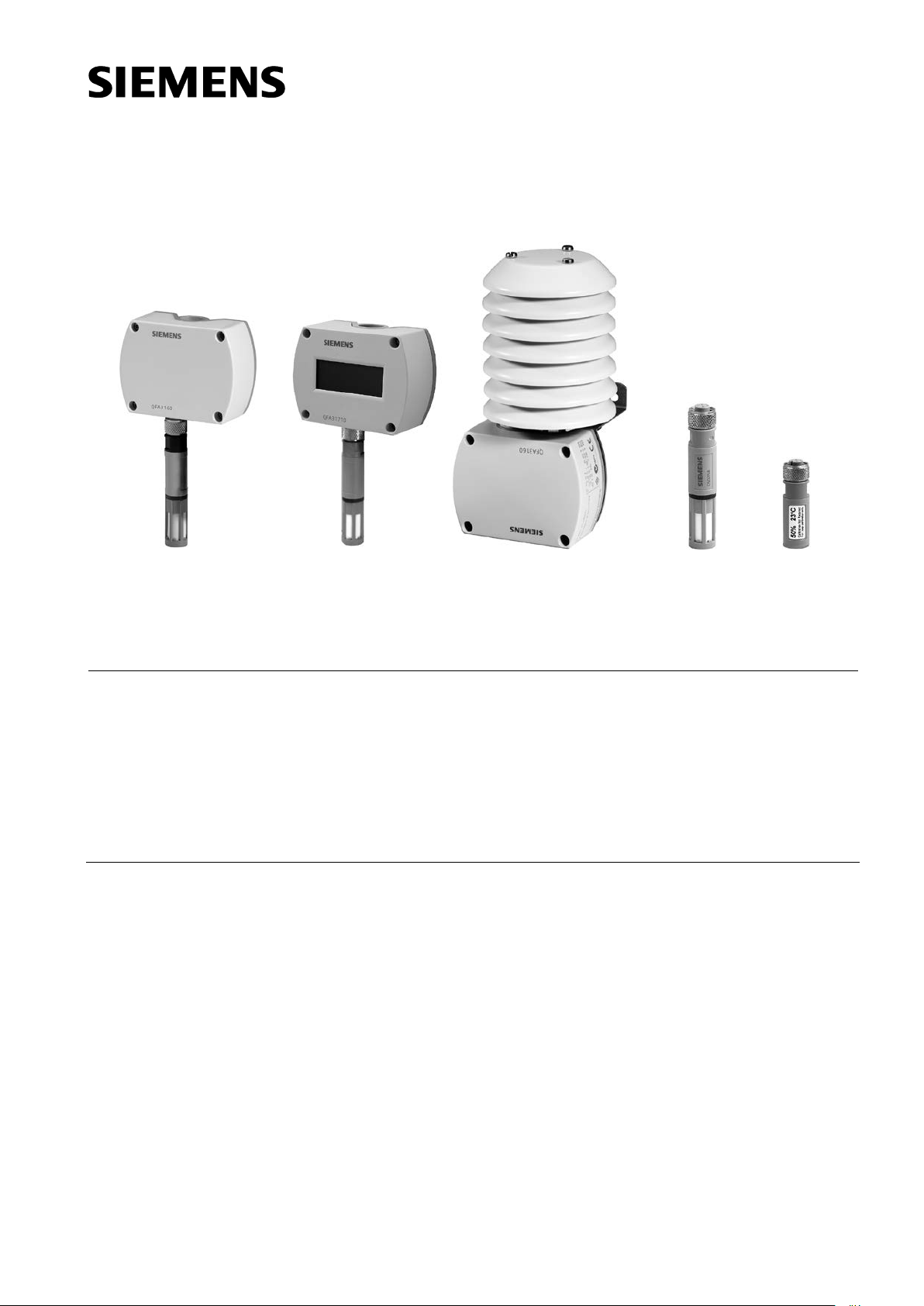
QFA31…
QFA31..D QFA31… with AQF3100
AQF3150 AQF3153
Symaro™
Room sensors
QFA31…
for relative humidity (high accuracy) and temperature
1858P01
1858P02
1859P02
1859P04
• Operating voltage AC 24 V / DC 13.5...35 V
• Signal output DC 0...10 V / 4…20 mA for relative humidity and temperature
• Very high measuring accuracy across the entire measuring range
• Capacitive humidity measurement
• Function test
• Range of use −40…+70 °C / 0…100 % r. h.
with LCD display
−25…+70 °C / 0…100 % r. h.
Use
The QFA31… is for use in ventilation and air conditioning plants where high accuracy
and short response times for measuring relative humidity are required. The measuring
range covers the entire humidity range of 0…100 %.
Examples:
• Storage and production facilities in the paper, textile, pharmaceutical, food, chemical
CE1N1858en
2014-07-30
and electronics industry, etc.
• Laboratories
• Hospitals
• Indoor swimming-pools
• Computer and EDP centers
• Greenhouses
• With the AQF3100 accessory for outdoor use
Building Technologies
Page 2
Type summary
Type
Temperature
Temperature
Humidity
Humidity
Operating
Measured
QFA3100
None
None
0...100 %
active, DC 0...10 V
AC 24 V or
No
QFA3101
None
None
0...100 %
active, 4…20 mA
DC 13,5…35 V
No
QFA3160
0...50 °C / − 40…+70 °C
active, DC 0...10 V
0...100 %
active, DC 0...10 V
AC 24 V or
No
QFA3160D
0...50 °C / − 40…+70 °C
active, DC 0...10 V
0...100 %
active, DC 0...10 V
AC 24 V or
Yes
QFA3171
0...50 °C / − 40…+70 °C
active, 4…20 mA
0...100 %
active, 4…20 mA
DC 13,5…35 V
No
QFA3171D
0...50 °C / − 40…+70 °C
active, 4…20 mA
0...100 %
active, 4…20 mA
DC 13,5…35 V
Yes
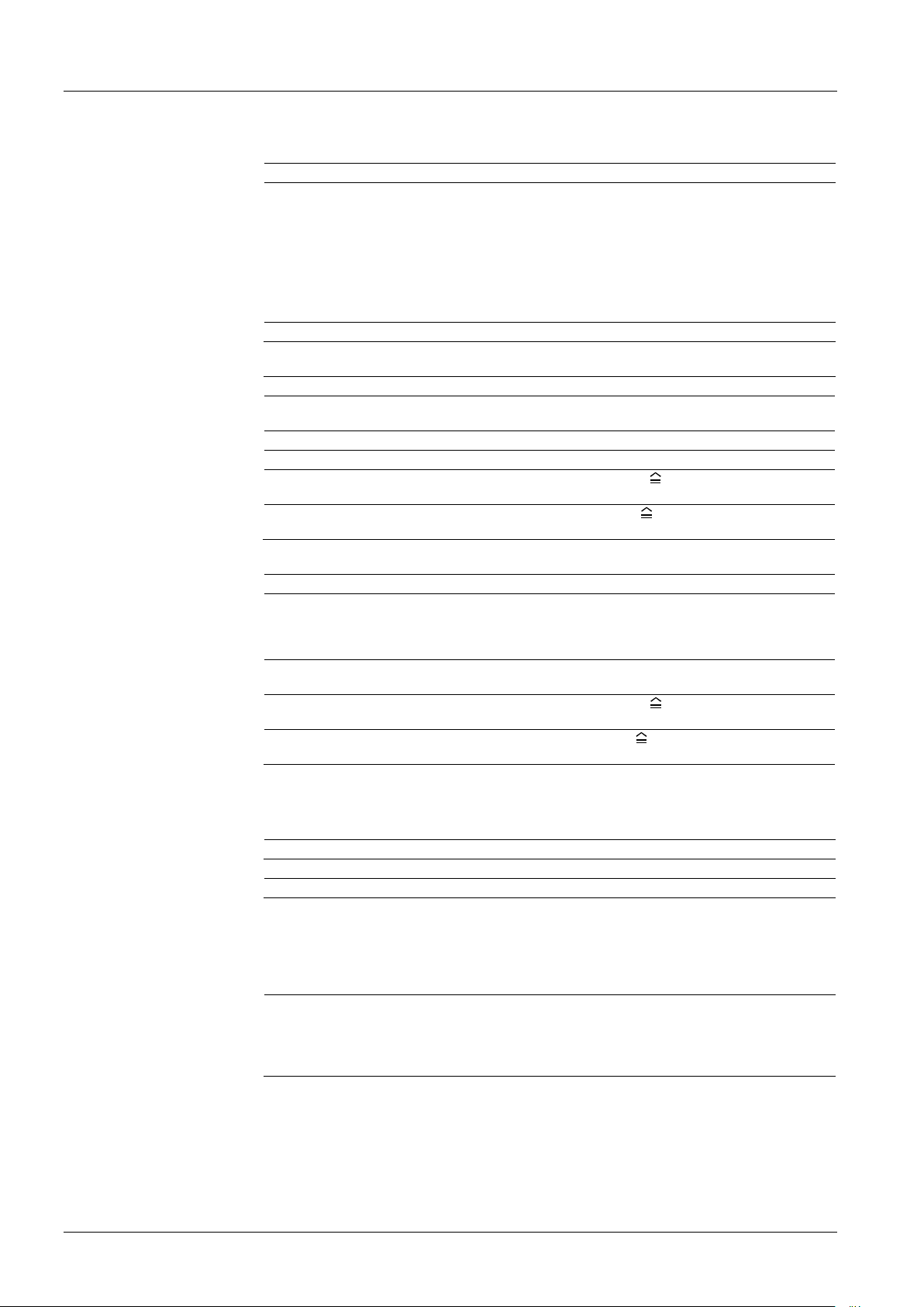
0 10 20 30 40
700
400
300
800
900
600
500
100
0
200
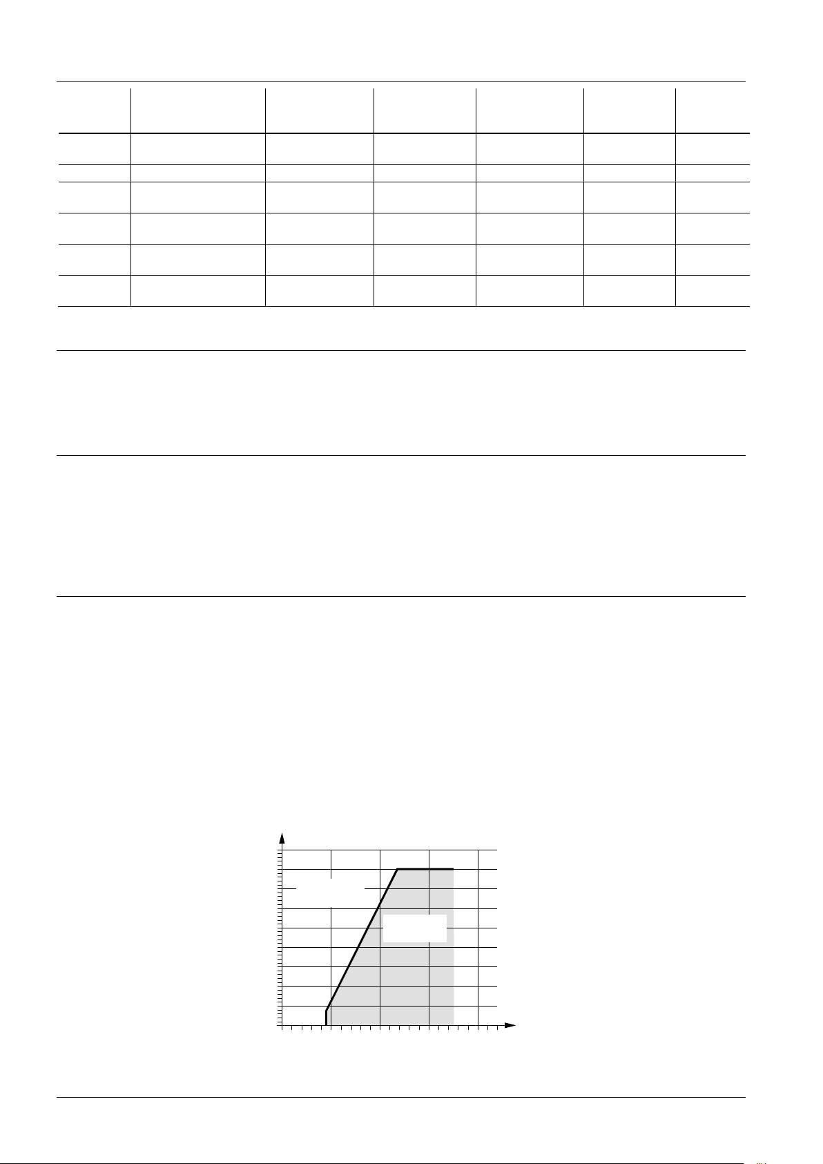
Burden [Ohm]
[DC V]
Operating voltage
Admissible
range
Inadmissible
range!
1858D02en
Relative humidity
Temperature
Burden diagram
reference
measuring range
/ − 35...+ 35 °C
/ − 35...+ 35 °C
/ − 35...+ 35 °C
/ − 35...+ 35 °C
Ordering and delivery
Equipment combinations
signal output
measuring range
signal output
voltage
DC 13,5…35 V
DC 13,5…35 V
DC 13,5…35 V
value dis-
play
When ordering, please give name and type reference, e.g.: Room sensor QFA3160
The outdoor mounting kit AQF3100, and the service set AQF3153 listed under “Accessories“ must be ordered as a separate item.
All systems and devices capable of acquiring and handling the sensor’s DC 0...10 V or
4...20 mA output signal.
When using the sensors for minimum or maximum selection, for averaging, or to calculate enthalpy, enthalpy difference, absolute humidity, and dew point, we recommend to
use the SEZ220 signal converter (see Data Sheet N5146).
Technical design
2/8
Siemens Room sensors QFA31… CE1N1858en
Building Technologies 2014-07-30
The sensor acquires the relative humidity in the room or in the outer air, respectively,
via its capacitive sensing element whose capacitance varies as a function of the relative humidity of the ambient air.
An electronic circuit converts the sensor’s signal to a continuous DC 0...10 V or
4…20 mA signal, corresponding to a relative humidity of 0...100 %.
The sensor acquires the temperature in the room or in the outer air, respectively, via its
sensing element whose electrical resistance changes as a function of the temperature.
This variation is converted to an active DC 0…10 V or 4…20 mA output signal, depending on the type of sensor. The output signal corresponds to a selectable temperature
range of 0…50 °C, –35…+35 °C, or −40...+70 °C.
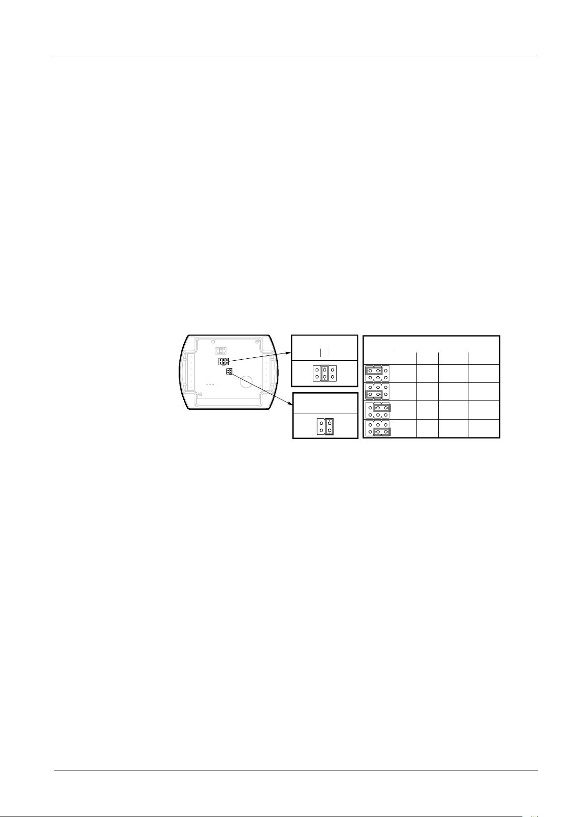
Output signal, terminaI I1 / I2
Page 3
Mechanical design
1
2 3
1 2 3
Range
5 V
10 V
5 V
0 V
10 V
5 V
0 V
5 V
U1 U2 I1 I2
20 mA
12 mA
4 mA
12 mA
12 mA
20 mA
12 mA
4 mA
°F °C
°F °C
QFA31...D
Measuring range
Test function active
1858Z03en
Display
temperature unit
Room sensor QFA31…
Measured value display
Setting elements
Malfunction
The room sensor consists of a housing, a printed circuit board, connection terminals
and a measuring tip. The two-part housing comprises a base and a screwed removable
cover.
A rubber seal is installed between base and cover in order to satisfy the requirements
of IP 65 degree of protection.
The measuring circuit and the setting element are accommodated on the printed circuit
board inside the cover, the connection terminals in the base. Housing and measuring
tip are screwed together. The measuring tip features a degree of protection of IP40.
The sensing elements are located at the end of the measuring tip, protected by a
screw-on filter cap.
Cable entry is made via the cable entry gland M16 supplied with the sensor, which
screws into the housing.
If the sensor is used outdoors, that opening must be closed off and the prepared hole
on the opposite side of the base knocked out.
The types QFA3160D and QFA3171D provide the measured values on its LCD display.
The following measured values are displayed alternately in intervals of 5 s:
Temperature: in °C or °F
Humidity: in % r. h.
The setting elements are located inside the cover. A setting element consists of 6 pins
and a jumper. It is used for selecting the required temperature measuring range and for
activating the test function. Types with LCD display have a second setting element with
4 pins and a jumper.
The different jumper positions have the following meaning:
• For the active temperature measuring range:
Jumper in the left position (R1) = − 35...+ 35 °C,
Jumper in the middle position (R2) = 0...50 °C (factory setting)
Jumper in the right position (R3) = −40...+70 °C
• For the active test function:
Jumper in the horizontal position: The values available at the signal output are those
given in the table “Test function active“.
• For the measured value display (QFA31…D)
- Jumper vertical in the right position = °C (factory setting)
- Jumper vertical in the left position = °F
• Should the temperature sensor become faulty a voltage of 0 V (4 mA) will be applied
at signal output U2 (I2) after 60 seconds, and the humidity signal at signal output U1
(I1) will reach 10 V (20 mA).
3/8
Siemens Room sensors QFA31… CE1N1858en
Building Technologies 2014-07-30
• Should the humidity sensor become faulty a voltage of 10 V (20 mA) will be applied at
signal output U1 (I1) after 60 seconds, and the temperature signal will remain active.
Page 4
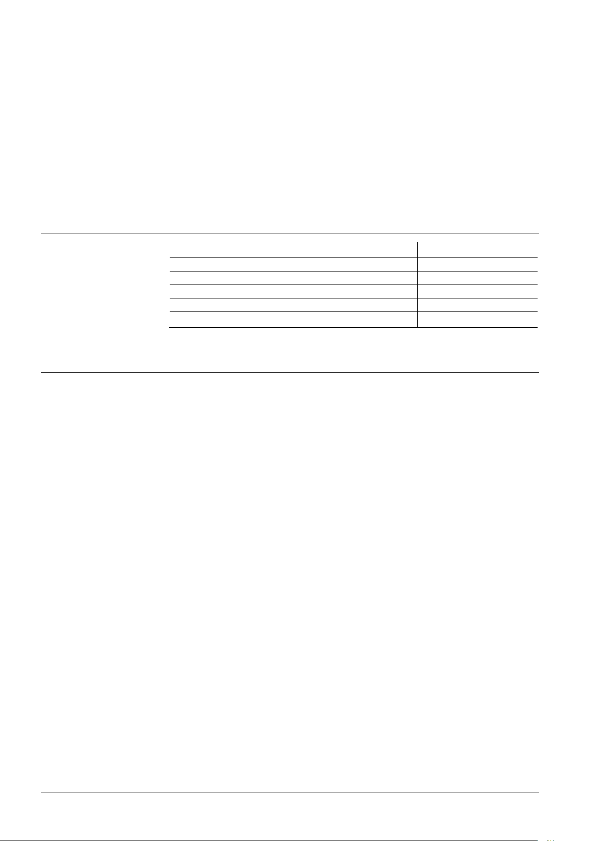
Name
Type reference
Outdoor mounting kit (incl. radiation shield)
AQF3100
Filter cap (for replacement)
AQF3101
Measuring tip (exchangeable for replacement)
AQF3150
Service set (for function test)
AQF3153
AQY2010
Outdoor mounting
kit AQF3100
Service set
AQF3153
Cable routing
and cable selection
Note to QFA3171(D)
The outdoor mounting kit consists of:
• 1 wall mounting bracket complete with radiation shield
• 4 Phillips-head screws K35 x 12
• 1 grommet M 16 x 1.5 with O-ring and nut M 16 x 1.5 for closing off the sensor’s ca-
ble entry hole if not required
Accessories
Engineering notes
The service set comprises three measuring tips without sensor element. Each tip signals a predefined temperature and humidity value to the basic unit:
• 85 % r. h., 40 °C
• 50 % r. h., 23 °C
• 20 % r. h., 5 °C
The fixed values are available at the signal outputs. The accuracy is the same as for
the test function. The measuring tips can be exchanged in operation.
3 m cable for remote measurement
A transformer for safety extra low-voltage (SELV) with separate windings for 100 %
duty is required to power the sensor. All safety regulations valid at the location of the
plant must be complied with when sizing and protecting the transformer.
When sizing the transformer, the sensor’s power consumption must be taken into consideration.
For the electrical connection of the sensor, refer to the Data Sheets of the devices with
which the sensor is used.
The maximum permissible cable lengths must be considered.
It must be considered for routing of cables that electrical interference is the greater, the
longer the cables run side by side and the smaller the distance between them. Use
shielded cables in environments having EMC problems.
Twisted pairs of cables are required for the secondary supply lines and the signal lines.
Terminals G1(+) and I1(−) for the humidity output must always be connected to power,
even if only terminals G2(+) and I2(−) of the temperature output are used!
4/8
Siemens Room sensors QFA31… CE1N1858en
Building Technologies 2014-07-30
Page 5
Mounting notes
Interior mounting
Mounting location
Caution!
Mounting position
Mounting Instructions
Outdoor mounting
Mounting location
Mounting position
Mounting Instructions
Note
QFA31… without AQF3100
Inside wall (not on outside wall!) of the room to be air conditioned; not in recesses, be-
hind curtains, above or close to heat sources or shelves; not on walls behind which a
chimney is located.
The sensor must not be exposed to direct solar radiation.
Install the sensor in the occupied space about 1.5 m above the floor and at least 50 cm
from the next wall.
• The seal between base and cover must not be removed, or else degree of protection
IP65 will be no longer ensured.
• The sensing elements inside the measuring tip are sensitive to shock and impact.
Avoid any such impact on mounting.
Without using the AQF3100 outdoor mounting kit, the sensor must not be mounted with
the measuring tip pointing upward.
Mounting Instructions are printed on the inner side of the package.
QFA31…
with AQF3100
Exterior wall, preferably on the North or Northwestern side of the building; if possible in
the middle of the wall, at least 2.5 above the ground.
Not above or below windows, above doors and ventilation shafts, below balconies or
eaves.
Commissioning notes
Disposal
The sensor with AQF3100 must be mounted in a vertical position (radiation shield at
the top).
Mounting Instructions are enclosed with the AQF3100.
When using the AQF3100 outdoor mounting kit, the sensor’s cable entry hole must be
closed off with the grommet and the prepared M16 cable entry on the opposite side
knocked out.
Prior to switching on power, check wiring.
On the sensor, select the required temperature measuring range.
Wiring and the output signals can be checked by making use of the test function (refer
to "Mechanical design").
We recommend not to use voltmeters or ohmmeters directly at the sensing element. In
the case of the simulated passive output signals, measurements with commercially
available meters cannot be made (measuring current too small).
The devices are considered electronics devices for disposal in term of European Directive 2012/19/EU and may not be disposed of as domestic waste.
• Dispose of the device via the channels provided for this purpose.
• Comply with all local and currently applicable laws and regulations.
5/8
Siemens Room sensors QFA31… CE1N1858en
Building Technologies 2014-07-30
Page 6
Technical data
Operating voltage
AC 24 V
AC/DC 24 V class 2 (US)
Frequency
50/60 Hz at AC 24 V
Exte
Fuse slow max. 10 A
Circuit breaker max. 13 A
Power source with current limit
10 A
Power consumption
≤ 1 VA
Max. perm. cable lengths
refer to Data Sheet of the device handling the
signal
Measuring range
0...100 % r. h.
Measuring accuracy at 23 °C and AC
0...100 % r.h.
± 2 % r. h.
Temperature dependency
≤ 0.05 % r.h./°C
Time constant
< 20 s
Output signal, linear (terminal U1)
DC 0...10 V
max. ±1 mA
Output signal, linear (terminal I1)
Burden
4…20 mA
refer to "Function"
Measuring range
0...50 °C (R2 = factory setting),
− 35...+35 °C (R1), −40...+70 °C (R3)
Sensing element
Pt 1000
Measuring accuracy at AC/DC 24 V
35...+70 °C
±
±
± 0.8 K
Time constant
8.5 min. (according to airflow and
wall coupling)
Output signal, linear (terminal U2)
DC 0...10 V
max. ±1 mA
Output signal, linear (termin
Burden
4..20 mA
refer to "Function"
Protection degree of housing
Unit with outdoor mounting kit
EN
IP65
IP40
IP65
Protection class
III according to EN 60730-1
Screw terminals
1 × 2.5 mm2 or 2 × 1.5 mm2
Cable entry gland (enclosed)
M 16 x 1.5
Operation to
Mechanical conditions
Class 4K2 to IEC 60 721
−
−
0...100 % r.h. (with condensation)
Class 3M2 to IEC 60 721-3-3
Transport to
Mechanical conditions
IEC 60 721
Class 2K
−
<
class 2M2
Power supply
Cable lengths for the measuring
signal
Functional data
“Humidity sensor"
Functional data
"Temperature sensor"
Degree of protection
Electrical connections
Environmental
conditions
± 20 % or DC13,5…35 V (SELV)
or
rnal supply line protection
or
Characteristic B, C, D according to
EN 60898
or
ation of max.
/DC 24 V in
0...100 % r.h.
0...100 % r.h.
in
23 °C
15...35 °C
<0.5 K
0.6 K
−
al I2)
Base unit
Measuring tip
60529
Climatic conditions
Temperature (housing with electronics)
LCD-display readable
40...+ 70 °C
25...+ 70 °C
0...50/− 35...+ 35/− 40...+70 °C
0...50/−35...+ 35/− 40...+70 °C
-3-4
Humidity
Climatic condition
Temperature
Humidity
40...+ 70 °C
95 % r.h.
-3-2
3
6/8
Siemens Room sensors QFA31… CE1N1858en
Building Technologies 2014-07-30
Page 7
Base
polycarbonate, RAL 7001 (silver-grey)
Housing cover
polycarbonate, RAL 7035 (light
Measuring tip
polycarbonate, RAL 7001 (silver-grey)
Filter cap
polycarbonate, RAL 7001 (silver
Mounting bracket
PA, RAL 7035 (light-grey)
Sensor (entirely)
silicon-free
Packaging
corrugated cardboard
Product
EN 60730
Automatic electrical controls for household
and similar use
Electromagnetic compatibility (Ap
For use in residential, commerce, lightindustrial and industrial environments
EU Conformity (CE)
CE1T1858xx *)
RCM Konformität
8000078879 *)
UL
UL 873, http://ul.com/database
The product environmental declarat
uct design and assessments (RoHS compliance, materials composition, packaging, environmental be
efit, disposal)
Incl. packaging
AQF3153
0.152 kg
0.175 kg
0.050 kg
0.066 kg
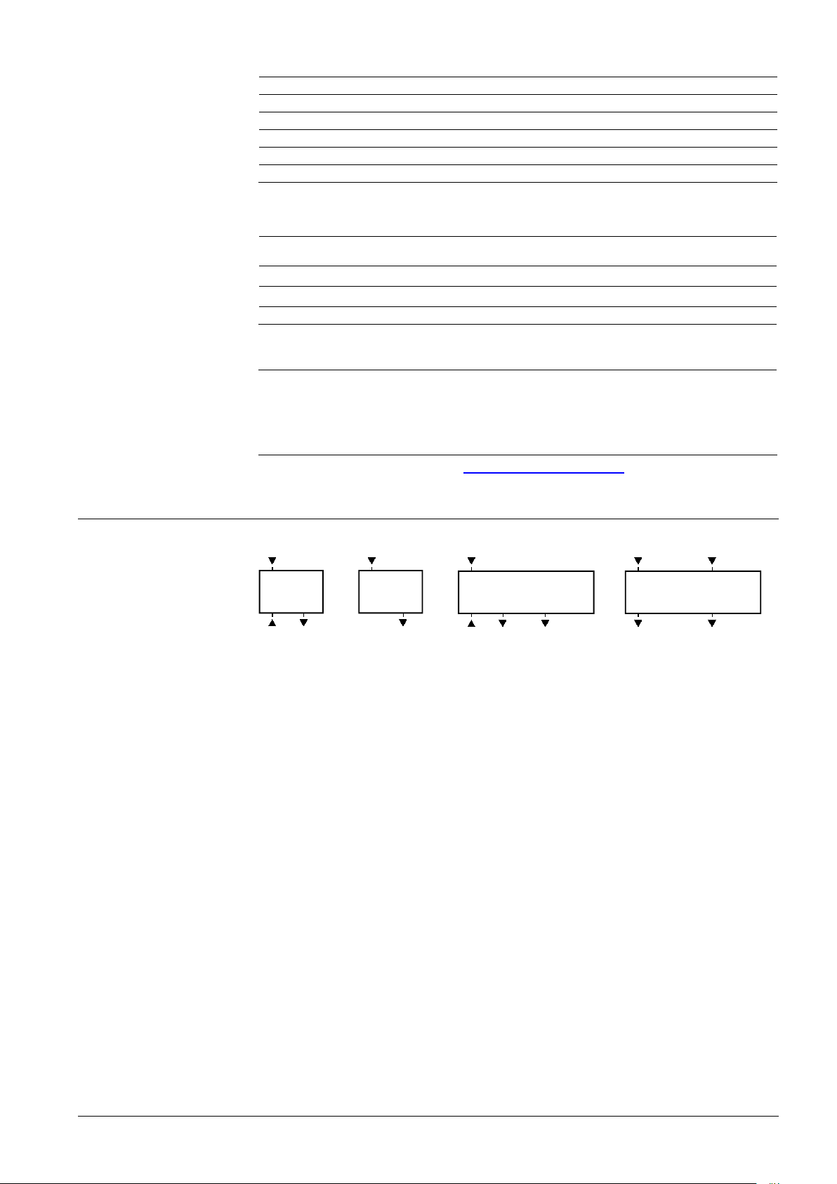
QFA3100
QFA3101
QFA3160(D)
G0
U1
G
1858G04
(r.h.)
I1
G1
1858G05
(r.h.)
G0
U1 U2
G
1858G01
(r.h.)
(R1 = −35...+35 °C /
R2 = 0...50 °C /
R3 =
−40
...+70 °C)
G2
I1
I2
G1
1858G03
(r.h.)
(R1 = −35...+35 °C /
R2 = 0...50 °C /
R3 =
−40
...+70 °C)
Materials and color
Standards and Directives
Environmental
compatibility
Weight
-grey)
standard
-1
plications)
ion CE1E1858*) contains data on environmentally compatible prod-
Without LCD-display
With LCD-display
AQF3150
*) The documents can be downloaded from http://siemens.com/bt/download.
Connection terminals
-grey)
n-
QFA3171(D)
G, G0 Operating voltage AC 24 V (SELV) or DC 13.5...35 V
G1, G2 Operating voltage DC 13.5...35 V
U1 Signal output DC 0...10 V for relative humidity 0...100 %
U2 Signal output DC 0...10 V for temperature range 0...50 °C (R2 = factory setting)
− 35...+35 °C (R1) or − 40…+70 °C (R3)
I1 Signal output 4…20 mA for relative humidit y 0...100 %
I2 Signal output 4…20 mA for temperature range 0...50 °C (R2 = factory setting)
− 35...+35 °C (R1) or − 40…+70 °C (R3)
Note on connection terminals of the QFA3171(D):
Terminals G1(+) and I1(−) for the humidity output must always be connected to power, even if only the temperature output G2(+) and I2(−) is used!
7/8
Siemens Room sensors QFA31… CE1N1858en
Building Technologies 2014-07-30
Page 8

Dimensions (all dimensions in mm)
80 39
84 60
28
10,5
ø 15
14,5
1858M01
62,8
41
M 16 x 1,5
Bohrplan
AQF3150
M 16 x 1,5
28
50
44
66
104
66
30 135
49
40
36
10,7
5,3
44
36
1858M02
22
89
193
58
Drilling plan
(with) LCD-display
QFA31… with AQF3100
2008 – 2014 Siemens Switzerland Ltd. Subject to change
QFA31…(D)
Dimensioning without
(41 with display)
8/8
Siemens Room sensors QFA31… CE1N1858en
Building Technologies 2014-07-30
 Loading...